ece 4710: lecture #17 1 transmitters communication tx generate modulated signal s(t) at the...
TRANSCRIPT
ECE 4710: Lecture #17 1
Transmitters
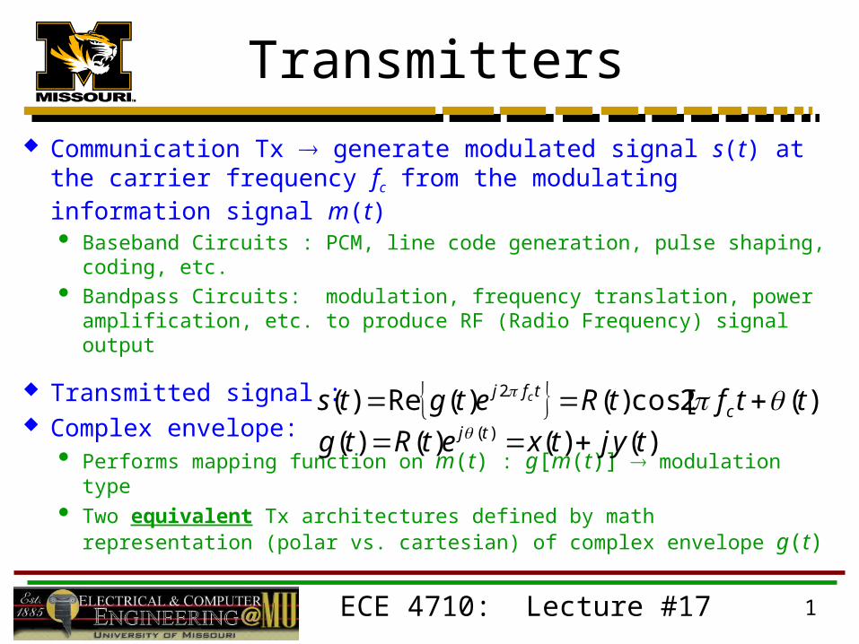
Communication Tx generate modulated signal s(t) at the carrier frequency fc from the modulating information signal m(t) Baseband Circuits : PCM, line code generation, pulse shaping,
coding, etc. Bandpass Circuits: modulation, frequency translation, power
amplification, etc. to produce RF (Radio Frequency) signal output
Transmitted signal : Complex envelope:
Performs mapping function on m(t) : g[m(t)] modulation type Two equivalent Tx architectures defined by math representation
(polar vs. cartesian) of complex envelope g(t)
)](2cos[)()(Re)( 2 ttftRetgts ctfj c
)()()()( )( tyjtxetRtg tj

ECE 4710: Lecture #17 2
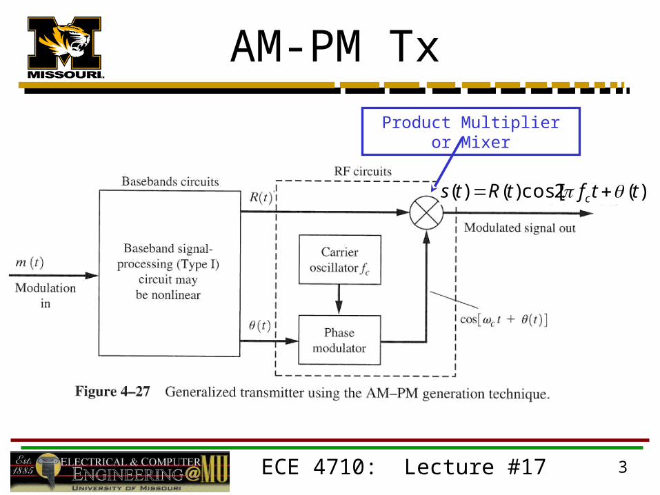
AM-PM Tx AM-PM Transmitter: baseband circuits generate R(t)
and/or (t) signals from m(t) Polar g(t) form R(t) = AM & (t) = PM
» Passed to RF circuits to modulate the carrier
Baseband Circuits» Linear or non-linear methods
Linear AM & Non-linear PM» Analog or Digital Circuits» Digital Circuits
Software algorithms for generation
Need ADC for m(t) and then two DACs for R(t) & (t)
ECE 4710: Lecture #17 3
AM-PM Tx
)](2cos[)()( ttftRts c
Product Multiplier or Mixer

ECE 4710: Lecture #17 4
AM-PM Mapping

ECE 4710: Lecture #17 5
Quadrature or IQ Tx
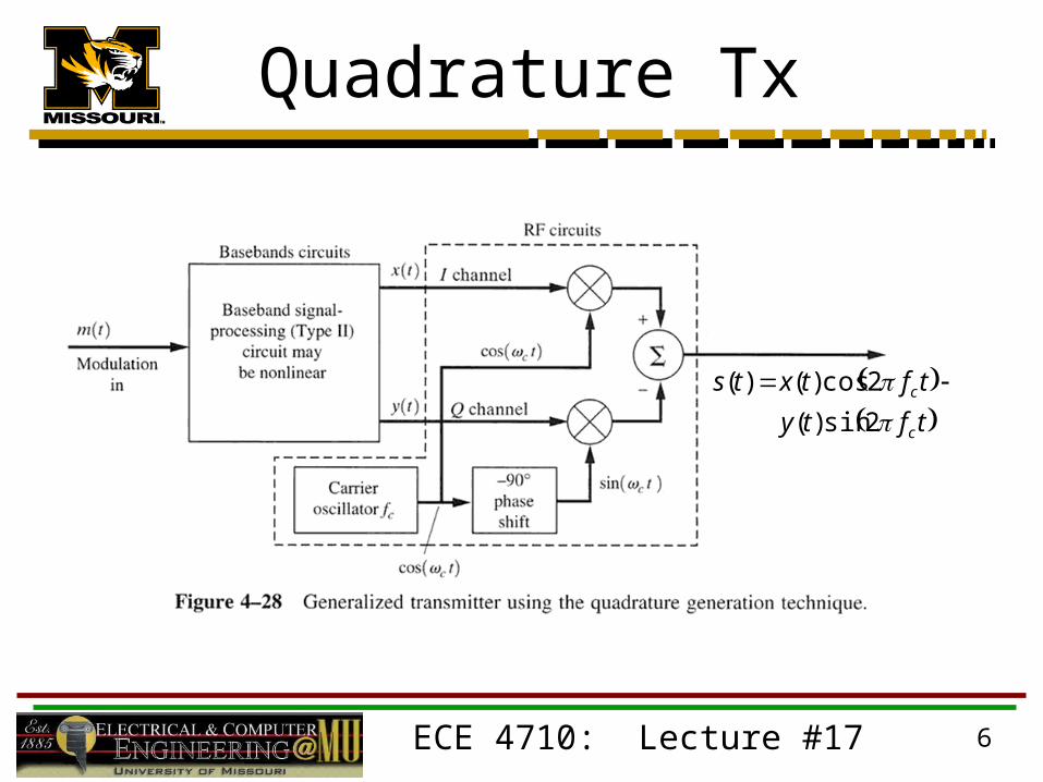
Quadrature Transmitter: baseband circuits generate x(t) and y(t) signals from m(t) Cartesian g(t) form x(t) = In-Phase & y(t) = Quadrature “IQ Tx”
» Passed to RF circuits to modulate two carriers
cos(2fc t) and sin(2fc t)Summed to produce quadrature output signal
Baseband circuits are usually digital» Software control
Easy algorithm updates» Multiple types of modulation done using same digital circuitry with
different software controlFlexible and cost-effective for mass production
ECE 4710: Lecture #17 6
Quadrature Tx
tfty
tftxts
c
c
2sin)(
2cos)()(

ECE 4710: Lecture #17 7
Quadrature Mapping
ECE 4710: Lecture #17 8
Transmitters RF circuits provide carrier and signal amplification Power Amplifier (PA) is usually final stage before antenna or
wired channel Class A or B Amplifiers
» Linear modulation methods (AM) Signal information contained in amplitude variation which cannot have
non-linear distortion Poor DC to RF efficiencies typically 40-65%
Class C Amplifiers» Non-linear modulation methods (FM, FSK, etc.)
Constant envelope signals Signal information contained in phase or frequency variation Excellent DC to RF efficiencies typically 80-90% Cost effective and very important for wireless systems using DC
battery supply
ECE 4710: Lecture #17 9
Transmitters AM-PM and Quadrature Tx’s have different
architecture but any type of modulated signal can be produced from either architecture Designer chooses architecture type based on
performance, cost, and state of art in circuit design In general (not always)
AM-PM for Analog Modulation Methods (AM, FM, etc.) Quadrature Tx for Digital Modulation Methods (PSK, FSK,
etc.)
ECE 4710: Lecture #17 10
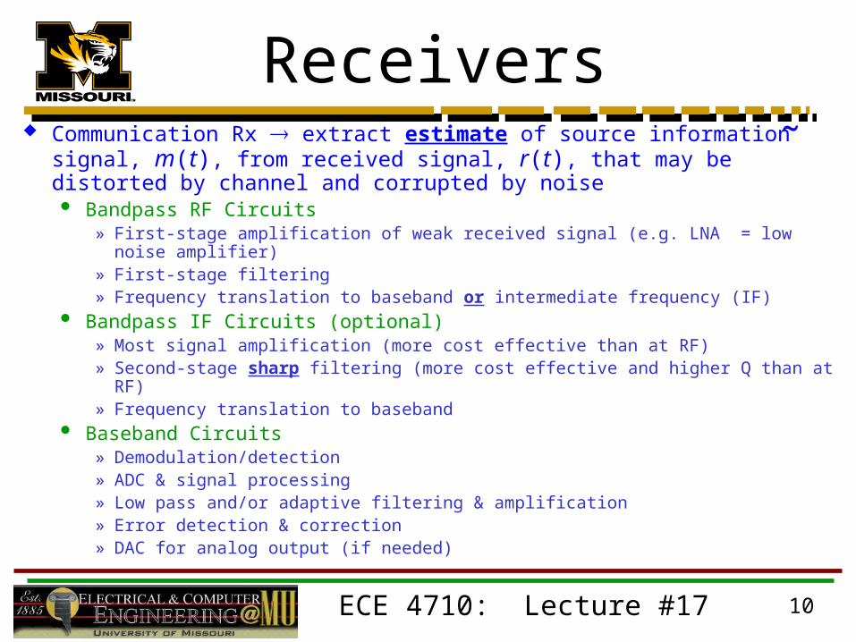
Receivers Communication Rx extract estimate of source information signal, m(t),
from received signal, r(t), that may be distorted by channel and corrupted by noise Bandpass RF Circuits
» First-stage amplification of weak received signal (e.g. LNA = low noise amplifier)» First-stage filtering» Frequency translation to baseband or intermediate frequency (IF)
Bandpass IF Circuits (optional)» Most signal amplification (more cost effective than at RF)» Second-stage sharp filtering (more cost effective and higher Q than at RF)» Frequency translation to baseband
Baseband Circuits» Demodulation/detection» ADC & signal processing» Low pass and/or adaptive filtering & amplification» Error detection & correction» DAC for analog output (if needed)
˜

ECE 4710: Lecture #17 11
Receivers Three basic types:
Tuned Radio Frequency (TRF)» Low cost, low performance
SuperHeterodyne (SH)» Most widely used high-performance Rx» Radar, AM/FM/TV broadcast, satellite communications, etc.
Zero-IF (ZIF) or Homodyne» Specialized applications like wireless handsets» Enable “system on chip” Rx designs using 2 chips
1 RF MMIC and 1 baseband DSP ASIC
ECE 4710: Lecture #17 12
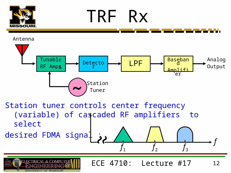
TRF Rx
Station tuner controls center frequency (variable) of cascaded RF amplifiers to select
desired FDMA signal :
˜
Antenna
TunableRF Amps
Detector LPFBasebandAmplifier
AnalogOutput
StationTuner
˜̃ ff1 f2 f3
ECE 4710: Lecture #17 13
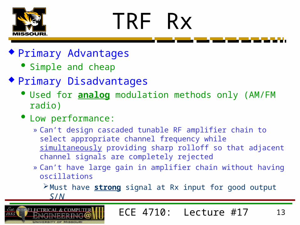
TRF Rx Primary Advantages
Simple and cheap Primary Disadvantages
Used for analog modulation methods only (AM/FM radio) Low performance:
» Can’t design cascaded tunable RF amplifier chain to select appropriate channel frequency while simultaneously providing sharp rolloff so that adjacent channel signals are completely rejected
» Can’t have large gain in amplifier chain without having oscillationsMust have strong signal at Rx input for good output S/N

ECE 4710: Lecture #17 14
SuperHeterodyne Rx
IFFilter
˜
Antenna
Low NoiseRF Amp
LPF
BasebandAmplifier
Digital orAnalogOutput
LocalOscillator
Mixer
Station Tuning Circuit
IFAMP
Demod /Detector
DSP
ADC, Bit Detection, Decoding, Adaptive Filter,
Error Correction, etc.
fc
fLO
fc + fLO
fc – fLO
-fc + fLO
-fc – fLO
fIF = -fc + fLO