eclipse ehx system logic maestro. module objective introduce logic maestro to the user elements ►...
TRANSCRIPT
Eclipse EHX SystemLogic Maestro
Module Objective
Introduce Logic Maestro to the user
Elements► What is Logic Maestro► How does Logic Maestro relate to the EHX map► Creating Logic Maestro Diagrams ► Worked practical example► Hands On
LOGIC MAESTRO
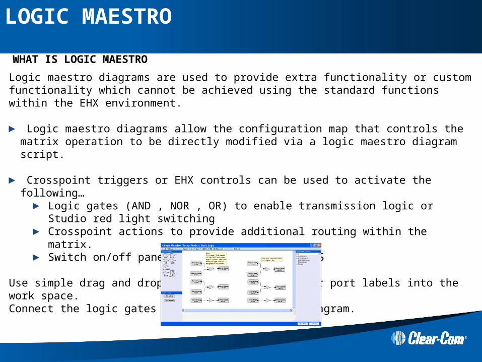
Logic maestro diagrams are used to provide extra functionality or custom functionality which cannot be achieved using the standard functions within the EHX environment.
► Logic maestro diagrams allow the configuration map that controls the matrix operation to be directly modified via a logic maestro diagram script.
► Crosspoint triggers or EHX controls can be used to activate the following…► Logic gates (AND , NOR , OR) to enable transmission logic or Studio red light switching► Crosspoint actions to provide additional routing within the matrix.► Switch on/off panel LEDS, microphone and LS
Use simple drag and drop to move logic symbols or port labels into the work space. Connect the logic gates to produce your logic diagram.
WHAT IS LOGIC MAESTRO
LOGIC MAESTRO

Logic Maestro Manager is installed as part of the standard EHX installation on ECS V5.1 or above
► Logic Maestro manager screen allows the user to select which Logic Maestro diagrams or control macros to tag to a configuration
► Logic Maestro diagrams are universal and can be tagged to any configuration map / system. As long as the control labels or port labels or groups used in the diagrams appear in the configuration map to which the scripts are tagged to.
► Logic Maestro manager screen also allows the user to ► Create new logic maestro diagrams or control macros► Import logic maestro diagrams or control macros► Delete, Export or Clone (copy) logic maestro diagrams or
control macros
► When a configuration is imported, exported or uploaded from the matrix. The tagged logic maestro diagrams are also included
WHAT IS LOGIC MAESTRO
LOGIC MAESTRO
Examples of what Logic Maestro diagrams can be used for:
► To enable or disable a route between any Local source and Local destination, which may be conditional on the status of other Crosspoints, Controls, Routes or GPIs. Enable priority routes to be setup
► The controls used in Logic Maestro can also be programmed with routes or attached to GPIs and Vox actions
► Enable or disable a panel’s loudspeaker (dimming/ muting)
► Allow the user to remotely mute a panel’s microphone
► Allow the user to remotely enable / disable a panel’s headset/ microphone selection
► Allow the user to flash the Key LED on a panel
Note: Existing Control Macros can also be accessed using the Logic Maestro Manager screen
WHAT IS LOGIC MAESTRO
LOGIC MAESTRO
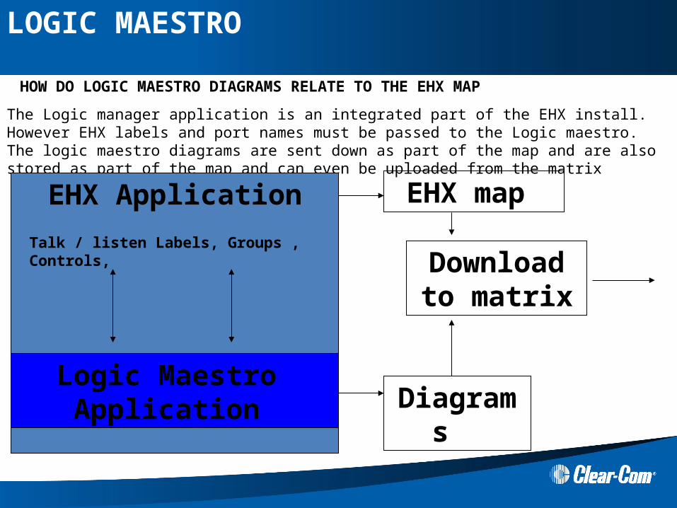
The Logic manager application is an integrated part of the EHX install. However EHX labels and port names must be passed to the Logic maestro. The logic maestro diagrams are sent down as part of the map and are also stored as part of the map and can even be uploaded from the matrix
EHX Application
Talk / listen Labels, Groups , Controls,
Logic Maestro Application Diagrams
Download to matrix
EHX map
HOW DO LOGIC MAESTRO DIAGRAMS RELATE TO THE EHX MAP
LOGIC MAESTRO
Because Logic Maestro diagrams can be applied to any map. It is Clear-Coms’ aim that
► Common diagrams will be shared within the ClearCom user community via the partner login web site
► Users will quickly learn to cut and paste functions from one diagram to another in order to achieve the required function
► Common diagrams that appear to be used at most installations will be transferred into the main EHX application
►Universal Passcode (Logic Maestro) 934CMAC5B44841CE05AD
► Clear-Com Engineers will aid users to generate Logic maestro diagrams (in some cases this will be a paid for service)
CLEARCOM LOGIC DIAGRAM USERS
LOGIC MAESTRO
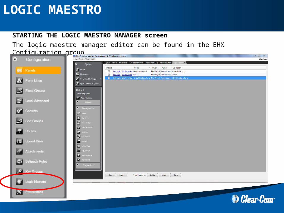
The logic maestro manager editor can be found in the EHX Configuration group
STARTING THE LOGIC MAESTRO MANAGER screen
LOGIC MAESTRO
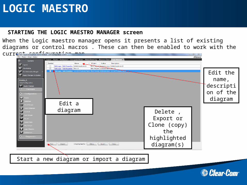
When the Logic maestro manager opens it presents a list of existing diagrams or control macros . These can then be enabled to work with the current configuration map
Edit a diagram
Edit the name,
description of the
diagram
Start a new diagram or import a diagram
Delete , Export or Clone (copy) the highlighted
diagram(s)
STARTING THE LOGIC MAESTRO MANAGER screen
LOGIC MAESTRO

Selecting Edit Logic will open a new logic maestro diagram screen. Use simple drag and drop to move logic symbols or port labels into the work space. Connect the logic gates to produce your logic diagram.
BASIC LOGIC MAESTRO PROGRAMMER
Drag and drop the logic gates
Drag and drop config elements (panels,
interfaces, controls , groups) into the
diagram
Online complier warns user of any errors
Controls can be attached to panel keys or GPI
inputs using EHX
LOGIC MAESTRO
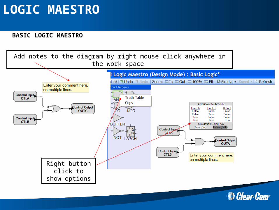
Add notes to the diagram by right mouse click anywhere in the work space
Right button click to show options
BASIC LOGIC MAESTRO
LOGIC MAESTRO
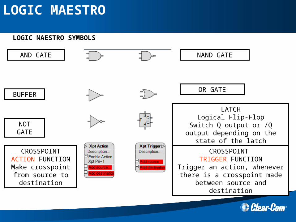
AND GATE
BUFFER
NOTGATE
NAND GATE
OR GATE
LATCHLogical Flip-Flop
Switch Q output or /Q output depending on the state of the latch
CROSSPOINT ACTION FUNCTIONMake crosspoint from source to destination
CROSSPOINT TRIGGER FUNCTION
Trigger an action, whenever there is a crosspoint made between source and
destination
LOGIC MAESTRO SYMBOLS
LOGIC MAESTRO

EHX Control label Input GATE
Permanent OFF trigger
PANEL ACTION FUNCTIONSwitch on Panel actionsLS Cut / DimLED on/off/flashMIC muteHeadset select
LOGIC MAESTRO SYMBOLS
EHX Control label Output
GATE
Permanent ON trigger
LOGIC MAESTRO
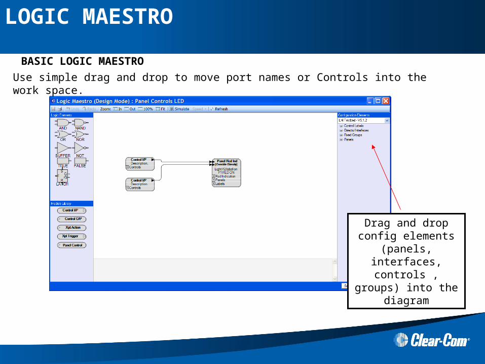
Use simple drag and drop to move port names or Controls into the work space.
Drag and drop config elements (panels,
interfaces, controls , groups) into the
diagram
BASIC LOGIC MAESTRO
LOGIC MAESTRO

LOGIC MAESTRO MAIN TOOLBAR
Save – diagram to EHX config
Print out the diagram
Undo / Redo functions
Simulation mode
Run a simulation of the logic
Select the Speed option to change the speed of the
simulation
Refresh – config map elements (ports names etc..) If a new port or
control is added to in EHX while the logic programmer is open – use refresh to pick up the new
labels
Select which config to read port labels from
LOGIC MAESTRO
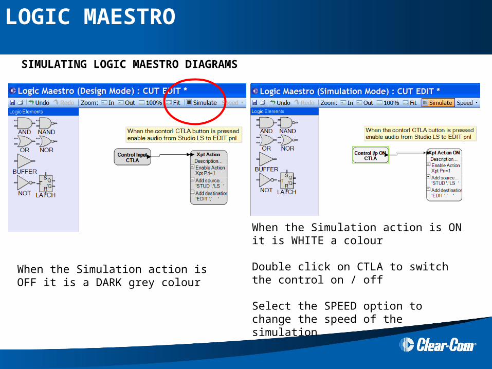
SIMULATING LOGIC MAESTRO DIAGRAMS
When the Simulation action is OFF it is a DARK grey colour
When the Simulation action is ON it is WHITE a colour
Double click on CTLA to switch the control on / off
Select the SPEED option to change the speed of the simulation
LOGIC MAESTRO
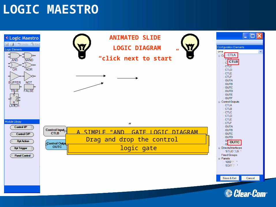
ANIMATED SLIDE
LOGIC DIAGRAM
“click next to start”
A SIMPLE “AND” GATE LOGIC DIAGRAM
NOW JUST SAVE AND DOWNLOAD THIS TO YOUR MATRIX
Expand the port list Select your Logic gate Select your port label Drag and drop the control Draw a line from the control to the logic gateDrag and drop the control
LOGIC MAESTRO
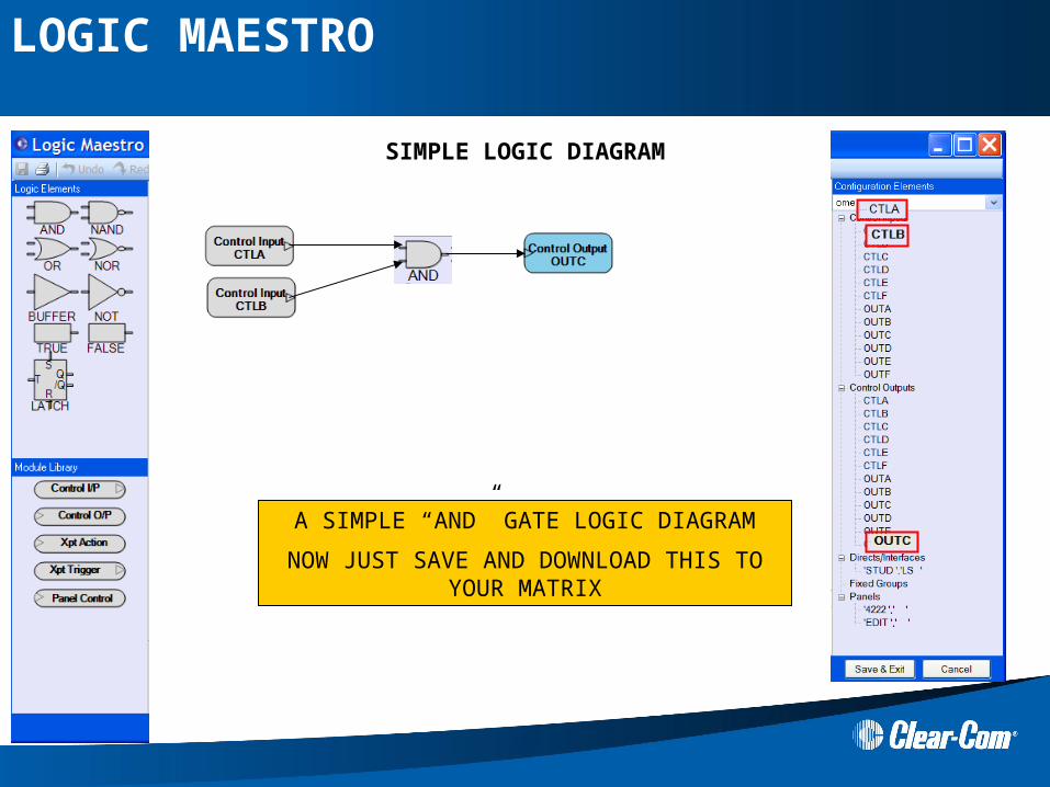
SIMPLE LOGIC DIAGRAM
A SIMPLE “AND” GATE LOGIC DIAGRAM
NOW JUST SAVE AND DOWNLOAD THIS TO YOUR MATRIX
LOGIC MAESTRO
Hands ON
WORKED EXAMPLE
LOGIC MAESTRO
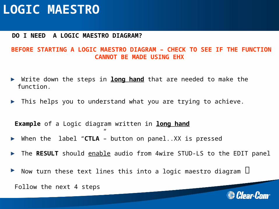
DO I NEED A LOGIC MAESTRO DIAGRAM?
BEFORE STARTING A LOGIC MAESTRO DIAGRAM – CHECK TO SEE IF THE FUNCTION CANNOT BE MADE USING EHX
► Write down the steps in long hand that are needed to make the function.
► This helps you to understand what you are trying to achieve.
Example of a Logic diagram written in long hand
► When the label “CTLA”– button on panel..XX is pressed
► The RESULT should enable audio from 4wire STUD-LS to the EDIT panel
► Now turn these text lines this into a logic maestro diagram
Follow the next 4 steps
LOGIC MAESTRO
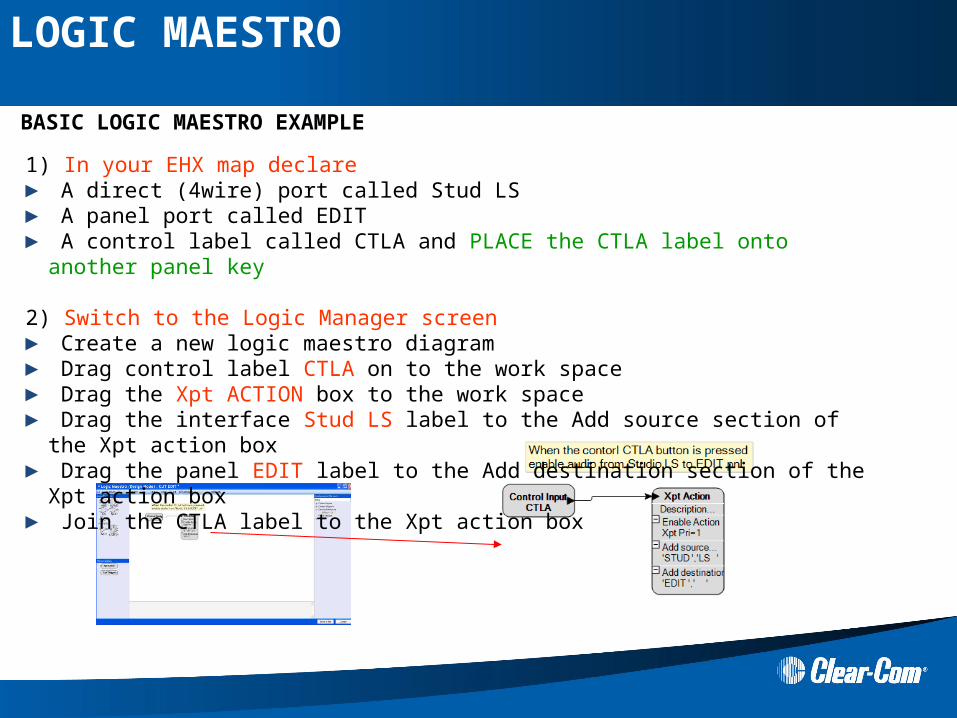
1) In your EHX map declare ► A direct (4wire) port called Stud LS► A panel port called EDIT ► A control label called CTLA and PLACE the CTLA label onto another panel key
2) Switch to the Logic Manager screen► Create a new logic maestro diagram► Drag control label CTLA on to the work space► Drag the Xpt ACTION box to the work space ► Drag the interface Stud LS label to the Add source section of the Xpt action box► Drag the panel EDIT label to the Add destination section of the Xpt action box► Join the CTLA label to the Xpt action box
BASIC LOGIC MAESTRO EXAMPLE
LOGIC MAESTRO
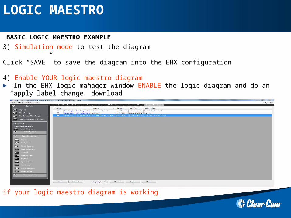
3) Simulation mode to test the diagram Click “SAVE” to save the diagram into the EHX configuration
4) Enable YOUR logic maestro diagram ► In the EHX logic manager window ENABLE the logic diagram and do an “apply label change”
download
Test if your logic maestro diagram is working
BASIC LOGIC MAESTRO EXAMPLE
LOGIC MAESTRO
Hands ON
Make simple logic diagrams,
► Make OR gate logic diagram ► Make AND gate logic diagram► Make a Xtp trigger logic diagram
► Remember to add relays / routes to controls in EHX
► Download your test map with apply label change
LOGIC MAESTRO
ADVANCE LOGIC DIAGRAMS
LOGIC MAESTRO - ADVANCED

1) Label not in current configuration.
If you import or open a logic diagram that has a red label – then the label cannot be found in the current configuration
ADVANCE FUNCTIONS
Use the refresh button to check the labels in the current config
Check EHX the port and control label names have been declared in the EHX configuration you are using
2) Advanced Gate functions
Right button click on a gate to
Add / remove inputs,
Change the logic gate type
Add comment
LOGIC MAESTRO - ADVANCED
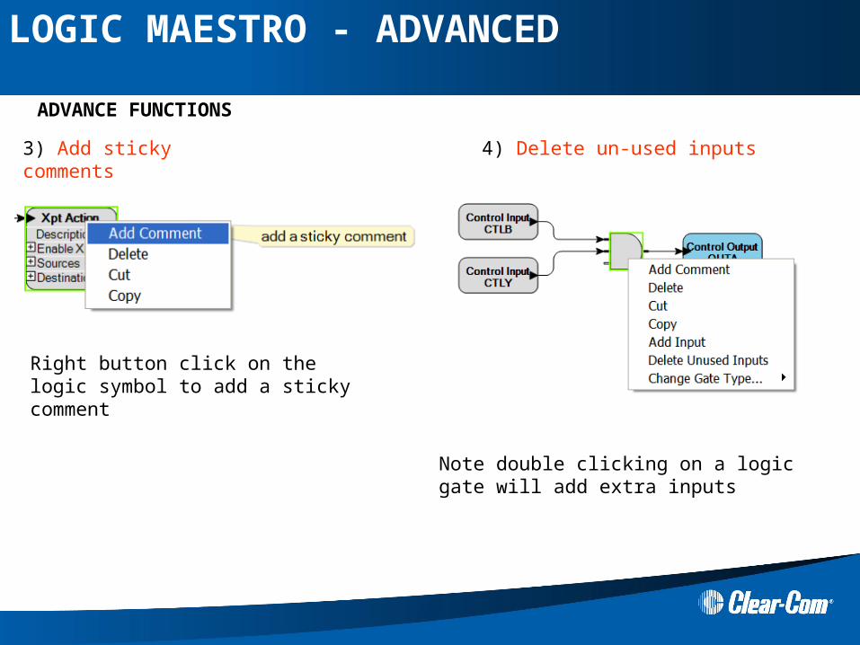
4) Delete un-used inputs
ADVANCE FUNCTIONS
Note double clicking on a logic gate will add extra inputs
Right button click on the logic symbol to add a sticky comment
3) Add sticky comments
LOGIC MAESTRO - ADVANCED
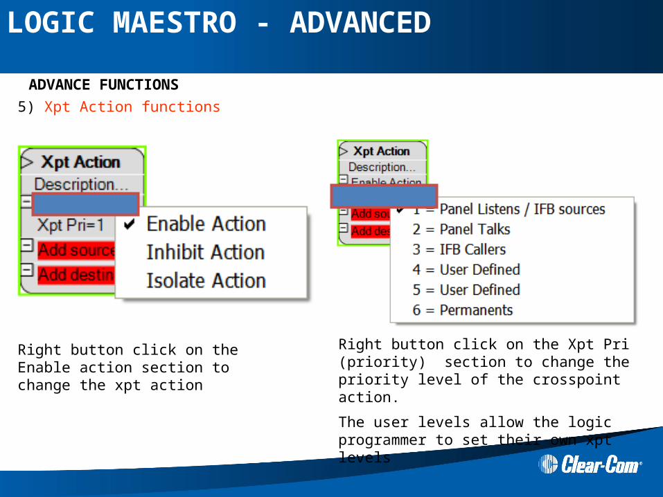
5) Xpt Action functions
ADVANCE FUNCTIONS
Right button click on the Enable action section to change the xpt action
Right button click on the Xpt Pri (priority) section to change the priority level of the crosspoint action.
The user levels allow the logic programmer to set their own xpt levels
LOGIC MAESTRO - ADVANCED
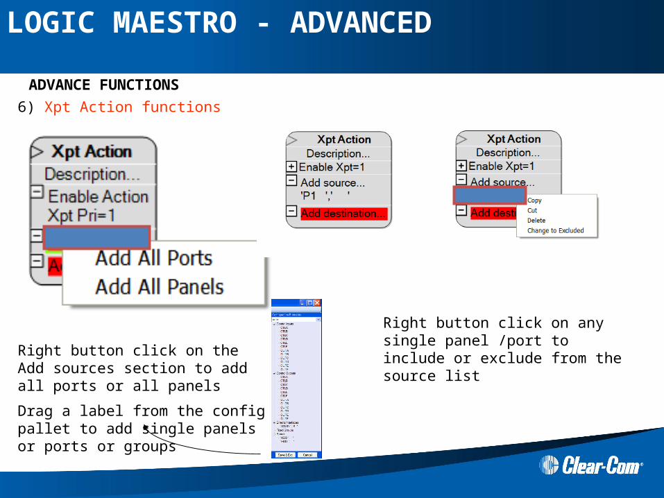
6) Xpt Action functions
ADVANCE FUNCTIONS
Right button click on the Add sources section to add all ports or all panels
Drag a label from the config pallet to add single panels or ports or groups
Right button click on any single panel /port to include or exclude from the source list
LOGIC MAESTRO - ADVANCED
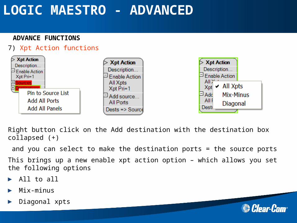
7) Xpt Action functions
ADVANCE FUNCTIONS
Right button click on the Add destination with the destination box collapsed (+)
and you can select to make the destination ports = the source ports
This brings up a new enable xpt action option – which allows you set the following options
► All to all
► Mix-minus
► Diagonal xpts
LOGIC MAESTRO - ADVANCED
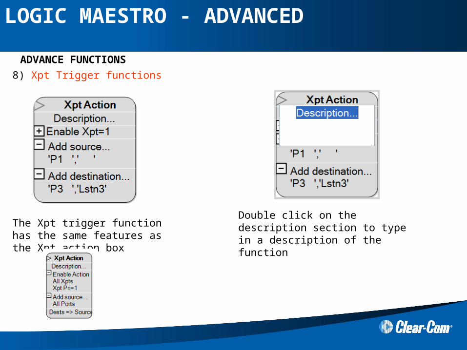
8) Xpt Trigger functions
ADVANCE FUNCTIONS
The Xpt trigger function has the same features as the Xpt action box
Double click on the description section to type in a description of the function
LOGIC MAESTRO - ADVANCED
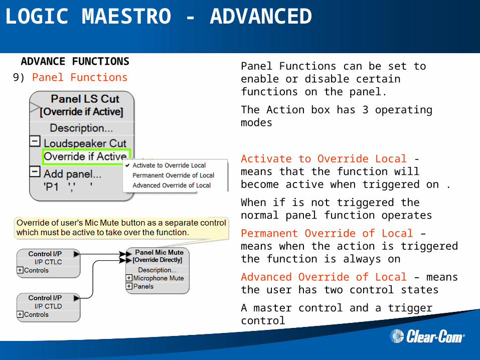
9) Panel Functions
ADVANCE FUNCTIONS Panel Functions can be set to enable or disable certain functions on the panel.
The Action box has 3 operating modes
Activate to Override Local - means that the function will become active when triggered on .
When if is not triggered the normal panel function operates
Permanent Override of Local – means when the action is triggered the function is always on
Advanced Override of Local – means the user has two control states
A master control and a trigger control
LOGIC MAESTRO - ADVANCED
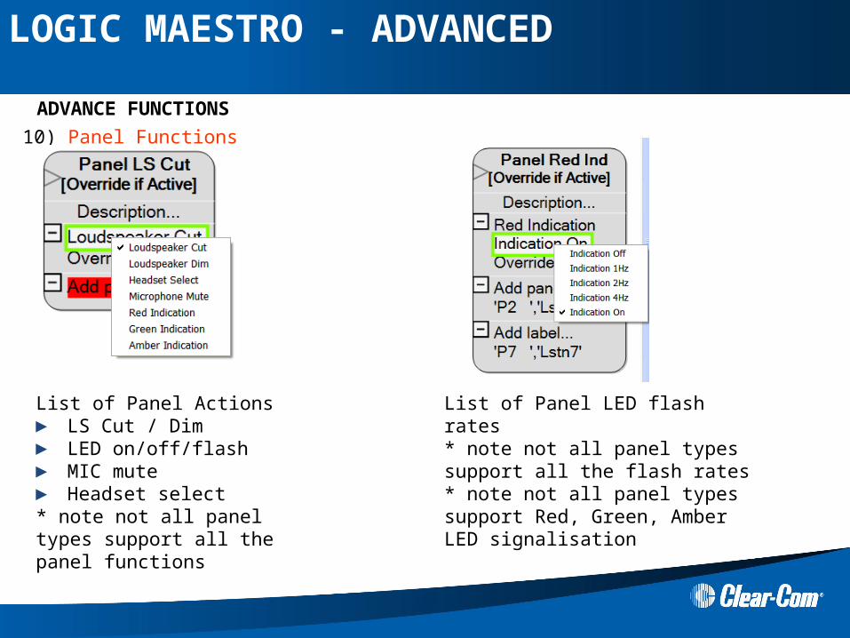
10) Panel Functions
ADVANCE FUNCTIONS
List of Panel Actions► LS Cut / Dim► LED on/off/flash► MIC mute► Headset select* note not all panel types support all the panel functions
List of Panel LED flash rates * note not all panel types support all the flash rates * note not all panel types support Red, Green, Amber LED signalisation
LOGIC MAESTRO - ADVANCED
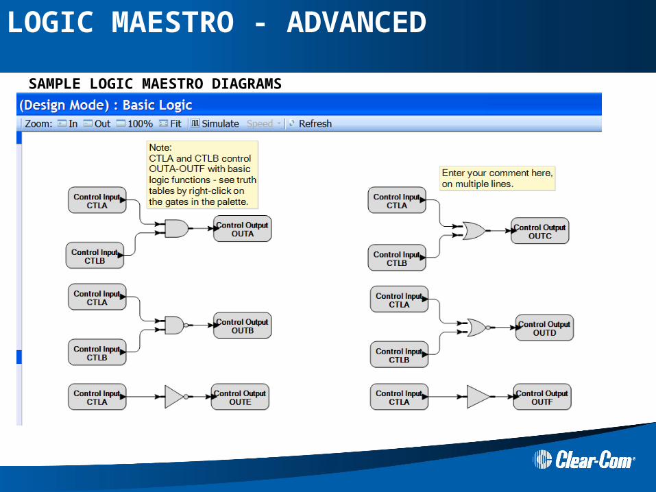
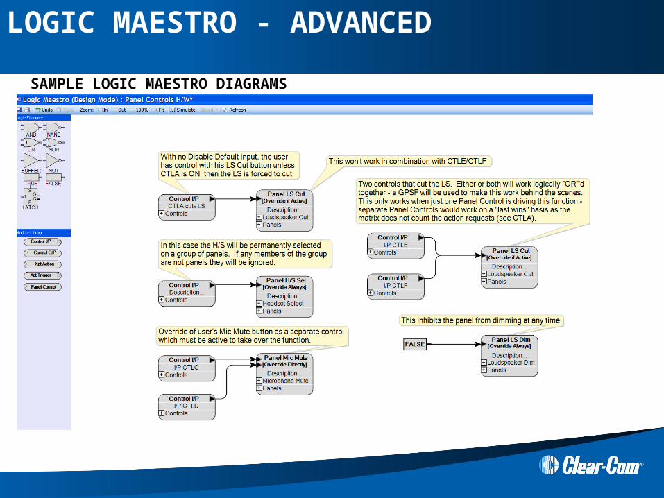
SAMPLE LOGIC MAESTRO DIAGRAMS
LOGIC MAESTRO - ADVANCED
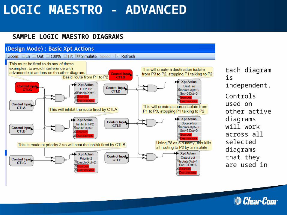
Each diagram is independent.
Controls used on other active diagrams will work across all selected diagrams that they are used in
SAMPLE LOGIC MAESTRO DIAGRAMS
LOGIC MAESTRO - ADVANCED
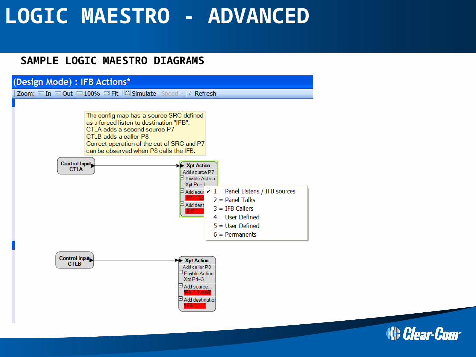
SAMPLE LOGIC MAESTRO DIAGRAMS
LOGIC MAESTRO - ADVANCED
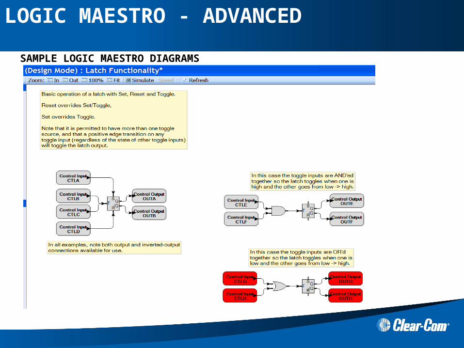
SAMPLE LOGIC MAESTRO DIAGRAMS
LOGIC MAESTRO - ADVANCED
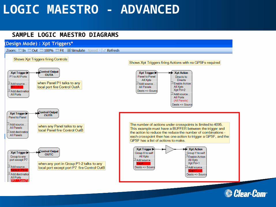
SAMPLE LOGIC MAESTRO DIAGRAMS
LOGIC MAESTRO - ADVANCED
SAMPLE LOGIC MAESTRO DIAGRAMS
LOGIC MAESTRO - ADVANCED
Hands ON
Make advanced logic maestro diagrams
► Use Panel Control Actions ► Use Xpt actions ► Use Xpt triggers ► Use the Latch (flip/flop) ► Make combinational logic using vox action and panel keys or matrix GPI’s from
EHX
► Download map with apply label change
LOGIC MAESTRO - ADVANCED

Thank you!