effect of basic isolations in the liquid storage...
TRANSCRIPT
Effect of basic isolations in the liquid storage tanks
Walid Samir MANSER University of Science and Technology Houari Boumediene, USTHB
Faculty of civil Engineering, LBE, Algiers, Algeria
e-mail: [email protected]
Mokhtar TOUATI University of Science and Technology Houari Boumediene, USTHB
Faculty of civil Engineering, LBE, Algiers, Algeria
e-mail: [email protected]
Mohamed CHABAAT University of Science and Technology Houari Boumediene, USTHB
Faculty of civil Engineering, LBE, Algiers, Algeria
e-mail: [email protected]
Rui Carneiro de BARROS Faculdade de Engenharia da Universidade do Porto (FEUP), Portugal
e-mail: [email protected]
Abstract Cylindrical metal storage tanks are widely used structures in the field of civil engineering ;
These installations are particularly used in industry where they are used to store all kinds of
products – which are for the most case toxic or flammable .Tanks are also used for municipal
purposes for the storage of drinking water .During earthquakes , these structures must be
preserved in order to avoid losing their precious content , causing reactions that can cause
more damage that the earthquake itself. A method of seismic isolation of these structures is
proposed in order to reduce the effects of the damage modes like: the elephant foot buckling
of the shell and the sloshing of the liquid contained in the tank.
Keywords: basic isolation; cylindrical metallic tanks; liquid’s sloshing; ansys
1. Introduction
In the design and calculation of structures , two general concepts are often used : The
first is the increase of the resistance capacity of the structure against the effects induced by the
seismic loads in particular in the horizontal direction :Indeed an increase in the capacity of
energy absorption by adding damping systems .The second is the introduction of seismic
isolation systems to reduce the effects of the different loads in the structure. The concept of
seismic isolation of the base of a structure is simple , the isolation system reduce the effect of
the horizontal component of seismic acceleration by the insertion of elements with reduced
Scientific Cooperations Journal of Civil Engineering and Architecture, Vol. 3, Issue. 1, December-2017
61
horizontal stiffness between the structure’s base and the foundations .This provides to the
structure a very small fundamental frequency so far from the seismic fundamental frequency.
2. Requirements of a base isolation system
A seismic isolation system shall perform the following functions: provide horizontal
flexibility while maintaining vertical stiffness, provide a damping to limit the relative
deformations and to increase the capacities of the special support and ensure sufficient rigidity
to support vertical loads.
3. Seismic isolation of liquid storage tanks
The idea of the seismic protection of cylindrical metallic tanks through the isolation of
their bases is very recent: In the early 2000’s, some works in this field was established (Wang
et al 2001, Shirmali and Jangid 2002). However, only a few practical applications have been
made (Tajirian 1990) and very few experiments have been made (Bergamo and al 2007). A
simple dynamic model of an isolated tank was constructed: The vibration period of the
impulsive component of the pressure decreases in the maximum amplification domain of the
spectral response, while the convective period is generally very large, this involve a high
efficiency of the isolation system in reducing the shear force at the base due to the impulsive
component of the pressure of the hydrodynamic pressure.
4. Failure modes of liquid storage tanks
Post seismic studies carried out after the earthquake revealed that the seismic response
is particular due to the fluid-ground-soil interaction. It was therefore necessary to develop
new methods for computing the effect of hydrodynamic forces on the structure. Mechanical
analog systems have been developed to provide simple means for analyzing the
hydrodynamic forces caused by the complex interaction: tank-liquid-soil interaction: Housner
was the first to develop mechanical analog systems to model the dynamic response of
rectangular and cylindrical tanks. The wall of the tank is considered to be rigid and the
displacement assumed to be small. Two or more discrete masses are used to represent the
contained liquid which moves with the wall of the tank .The upper part of the contained liquid
which is responsible for the liquid’s sloshing is represented by masses fixed on the wall of the
tanks by springs.
After that, Housner and Haroun developed a new mechanical system which takes
account the flexibility of the tank walls into consideration. Malhotra (2000) have use the
Scientific Cooperations Journal of Civil Engineering and Architecture, Vol. 3, Issue. 1, December-2017
62
results of this study to develop a simplified mechanical analogue system for the analysis of
flexible cylindrical tanks, this model become a real reference in the study and analysis of
liquid storage tanks .
After each earthquake, observations of the damage to the installations are made, in
order to assess losses but also to verify the validity of the standards, and to improve them
where necessary.
This paragraph presents generally two classical damage modes observed on the
cylindrical metallic tanks subjected to an excitation at their bases, namely the sloshing of the
liquid contained in the tank as well as the elephant foot buckling on the wall’s base.
4.1 The elephant foot buckling
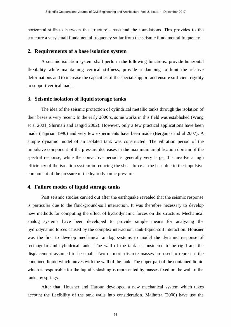
This kind of damage is a plastic buckling du to an excess in the normal stress in the
lower part of the tank (0< z <0,1H): It is mainly observed in large tanks (D/H) > 1.
Figure 1 The Elephant foot Buckling at the base of a damaged tank
4.2 The liquid’s sloshing
The sloshing phenomenon is an oscillation of the free surface of the liquid after the
excitation of the tank. During the earthquake, the fluid contained oscillated in a special way:
The upper part oscillates with great periods (convective part), while the rest of the liquid
(impulsive part ) has a movement similar to that of the rigid shell.
Scientific Cooperations Journal of Civil Engineering and Architecture, Vol. 3, Issue. 1, December-2017
63
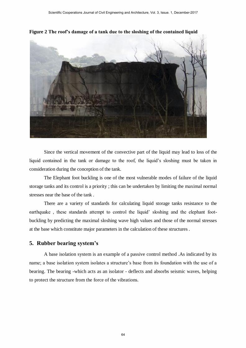
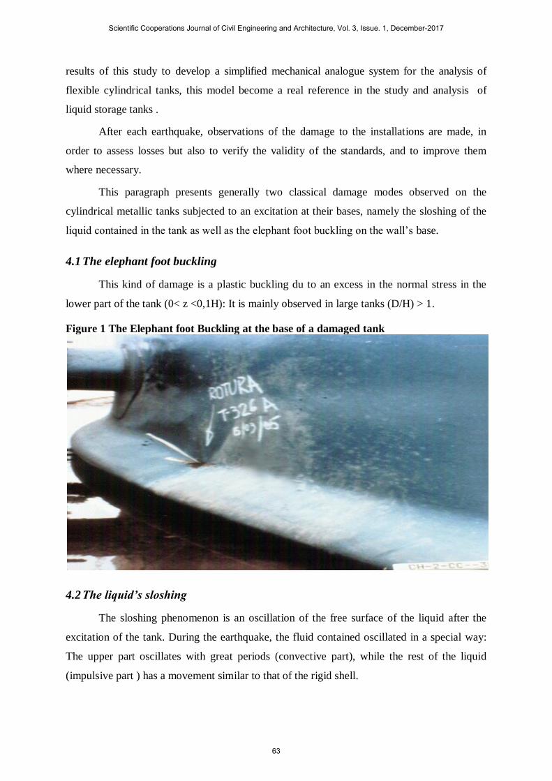
Figure 2 The roof’s damage of a tank due to the sloshing of the contained liquid
Since the vertical movement of the convective part of the liquid may lead to loss of the
liquid contained in the tank or damage to the roof, the liquid’s sloshing must be taken in
consideration during the conception of the tank.
The Elephant foot buckling is one of the most vulnerable modes of failure of the liquid
storage tanks and its control is a priority ; this can be undertaken by limiting the maximal normal
stresses near the base of the tank .
There are a variety of standards for calculating liquid storage tanks resistance to the
earthquake , these standards attempt to control the liquid’ sloshing and the elephant foot-
buckling by predicting the maximal sloshing wave high values and those of the normal stresses
at the base which constitute major parameters in the calculation of these structures .
5. Rubber bearing system’s
A base isolation system is an example of a passive control method .As indicated by its
name; a base isolation system isolates a structure’s base from its foundation with the use of a
bearing. The bearing -which acts as an isolator - deflects and absorbs seismic waves, helping
to protect the structure from the force of the vibrations.
Scientific Cooperations Journal of Civil Engineering and Architecture, Vol. 3, Issue. 1, December-2017
64
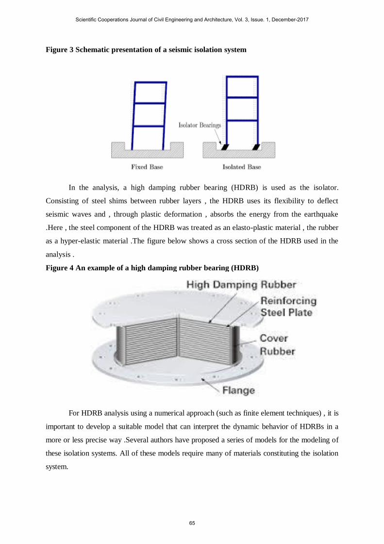
Figure 3 Schematic presentation of a seismic isolation system
In the analysis, a high damping rubber bearing (HDRB) is used as the isolator.
Consisting of steel shims between rubber layers , the HDRB uses its flexibility to deflect
seismic waves and , through plastic deformation , absorbs the energy from the earthquake
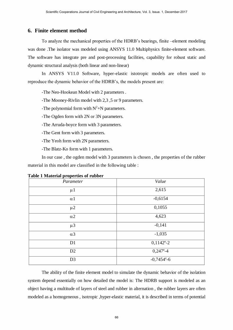
.Here , the steel component of the HDRB was treated as an elasto-plastic material , the rubber
as a hyper-elastic material .The figure below shows a cross section of the HDRB used in the
analysis .
Figure 4 An example of a high damping rubber bearing (HDRB)
For HDRB analysis using a numerical approach (such as finite element techniques) , it is
important to develop a suitable model that can interpret the dynamic behavior of HDRBs in a
more or less precise way .Several authors have proposed a series of models for the modeling of
these isolation systems. All of these models require many of materials constituting the isolation
system.
Scientific Cooperations Journal of Civil Engineering and Architecture, Vol. 3, Issue. 1, December-2017
65
6. Finite element method
To analyze the mechanical properties of the HDRB’s bearings, finite –element modeling
was done .The isolator was modeled using ANSYS 11.0 Multiphysics finite-element software.
The software has integrate pre and post-processing facilities, capability for robust static and
dynamic structural analysis (both linear and non-linear)
In ANSYS V11.0 Software, hyper-elastic istotropic models are often used to
reproduce the dynamic behavior of the HDRB’s, the models present are:
-The Neo-Hookean Model with 2 parameters .
-The Mooney-Rivlin model with 2,3 ,5 or 9 parameters.
-The polynomial form with N2+N parameters.
-The Ogden form with 2N or 3N parameters.
-The Arruda-boyce form with 3 parameters.
-The Gent form with 3 parameters.
-The Yeoh form with 2N parameters.
-The Blatz-Ko form with 1 parameters.
In our case , the ogden model with 3 parameters is chosen , the properties of the rubber
material in this model are classified in the following table :
Table 1 Material properties of rubber
Parameter Value
1 2,615
1 -0,6154
2 0,1055
2 4,623
3 -0,141
3 -1,035
D1 0,1142e-2
D2 0,247e-4
D3 -0,7454e-6
The ability of the finite element model to simulate the dynamic behavior of the isolation
system depend essentially on how detailed the model is: The HDRB support is modeled as an
object having a multitude of layers of steel and rubber in alternation , the rubber layers are often
modeled as a homogeneous , isotropic ,hyper-elastic material, it is described in terms of potential
Scientific Cooperations Journal of Civil Engineering and Architecture, Vol. 3, Issue. 1, December-2017
66
deformation energy U defining the deformation energy stored in the material per volume unit .
The rubber is modeled by the SOLID186 element while the steel layers are modeled
by the SHELL 63 element. The support that has been used in the study has the following
characteristics:
Table 2 Dimensions of the special bearing
Number of layers Thickness / layer (m)
Steel 19 0,002
Rubber 20 0,01
Steel plate 2 0,02
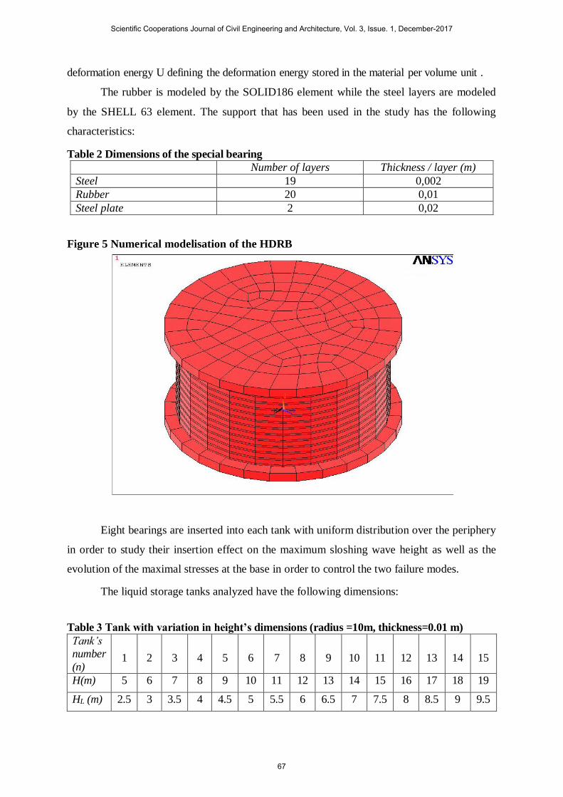
Figure 5 Numerical modelisation of the HDRB
Eight bearings are inserted into each tank with uniform distribution over the periphery
in order to study their insertion effect on the maximum sloshing wave height as well as the
evolution of the maximal stresses at the base in order to control the two failure modes.
The liquid storage tanks analyzed have the following dimensions:
Table 3 Tank with variation in height’s dimensions (radius =10m, thickness=0.01 m)
Tank’s
number
(n) 1 2 3 4 5 6 7 8 9 10 11 12 13 14 15
H(m) 5 6 7 8 9 10 11 12 13 14 15 16 17 18 19
HL (m) 2.5 3 3.5 4 4.5 5 5.5 6 6.5 7 7.5 8 8.5 9 9.5
Scientific Cooperations Journal of Civil Engineering and Architecture, Vol. 3, Issue. 1, December-2017
67
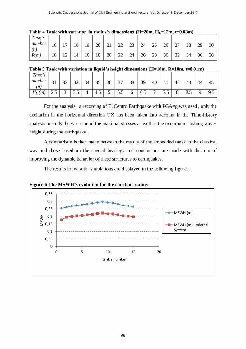
Table 4 Tank with variation in radius’s dimensions (H=20m, HL=12m, t=0.03m)
Tank’s
number
(n) 16 17 18 19 20 21 22 23 24 25 26 27 28 29 30
R(m) 10 12 14 16 18 20 22 24 26 28 30 32 34 36 38
Table 5 Tank with variation in liquid’s height dimensions (H=10m, R=10m, t=0.01m)
Tank’s
number
(n) 31 32 33 34 35 36 37 38 39 40 41 42 43 44 45
HL (m) 2.5 3 3.5 4 4.5 5 5.5 6 6.5 7 7.5 8 8.5 9 9.5
For the analysis , a recording of El Centro Earthquake with PGA=g was used , only the
excitation in the horizontal direction UX has been taken into account in the Time-history
analysis to study the variation of the maximal stresses as well as the maximum sloshing waves
height during the earthquake .
A comparison is then made between the results of the embedded tanks in the classical
way and those based on the special bearings and conclusions are made with the aim of
improving the dynamic behavior of these structures to earthquakes.
The results found after simulations are displayed in the following figures:
Figure 6 The MSWH’s evolution for the constant radius
0
0,05
0,1
0,15
0,2
0,25
0,3
0,35
0 5 10 15 20
MSW
H
tank's number
MSWH (m)
MSWH (m) IsolatedSystem
Scientific Cooperations Journal of Civil Engineering and Architecture, Vol. 3, Issue. 1, December-2017
68
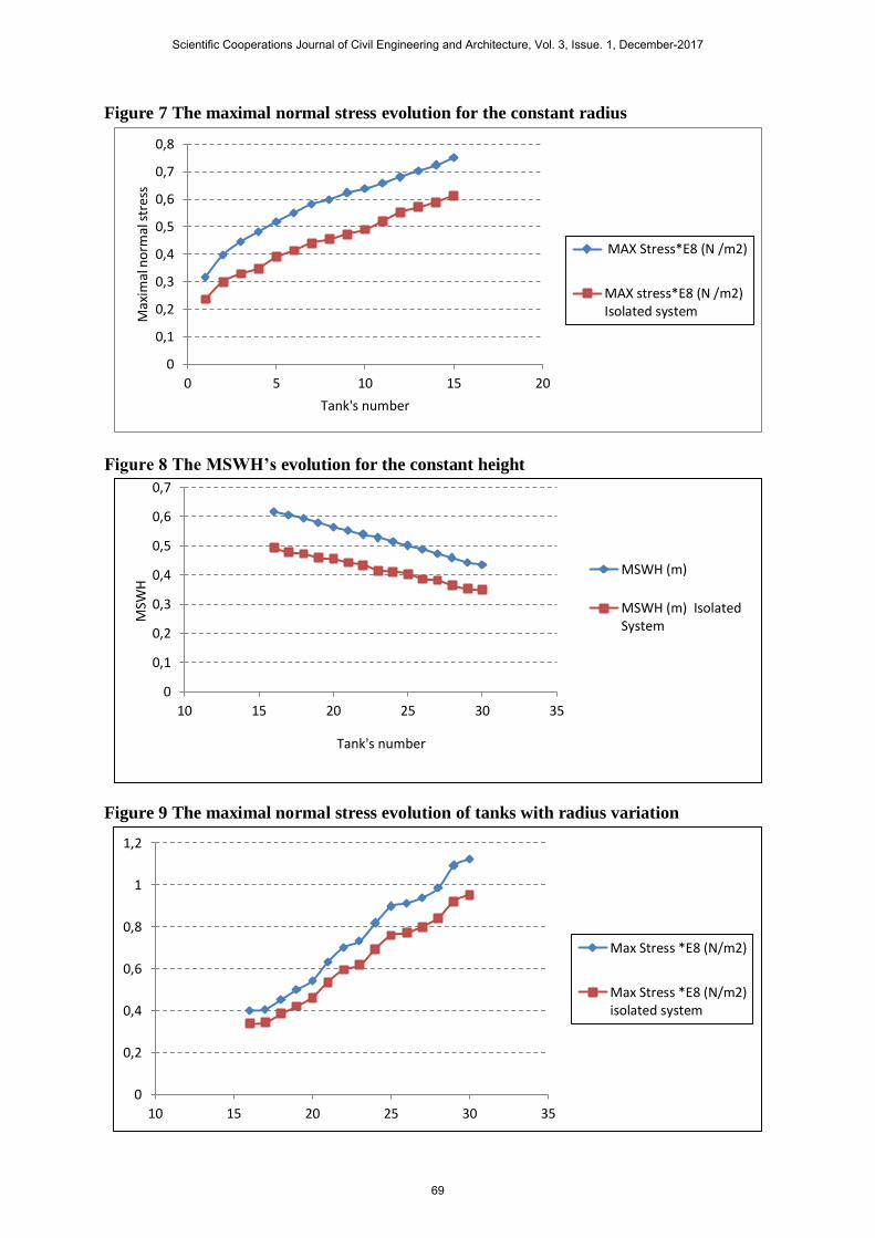
Figure 7 The maximal normal stress evolution for the constant radius
Figure 8 The MSWH’s evolution for the constant height
Figure 9 The maximal normal stress evolution of tanks with radius variation
0
0,1
0,2
0,3
0,4
0,5
0,6
0,7
0,8
0 5 10 15 20
Max
imal
no
rmal
str
ess
Tank's number
MAX Stress*E8 (N /m2)
MAX stress*E8 (N /m2)Isolated system
0
0,1
0,2
0,3
0,4
0,5
0,6
0,7
10 15 20 25 30 35
MSW
H
Tank's number
MSWH (m)
MSWH (m) IsolatedSystem
0
0,2
0,4
0,6
0,8
1
1,2
10 15 20 25 30 35
Max Stress *E8 (N/m2)
Max Stress *E8 (N/m2)isolated system
Scientific Cooperations Journal of Civil Engineering and Architecture, Vol. 3, Issue. 1, December-2017
69
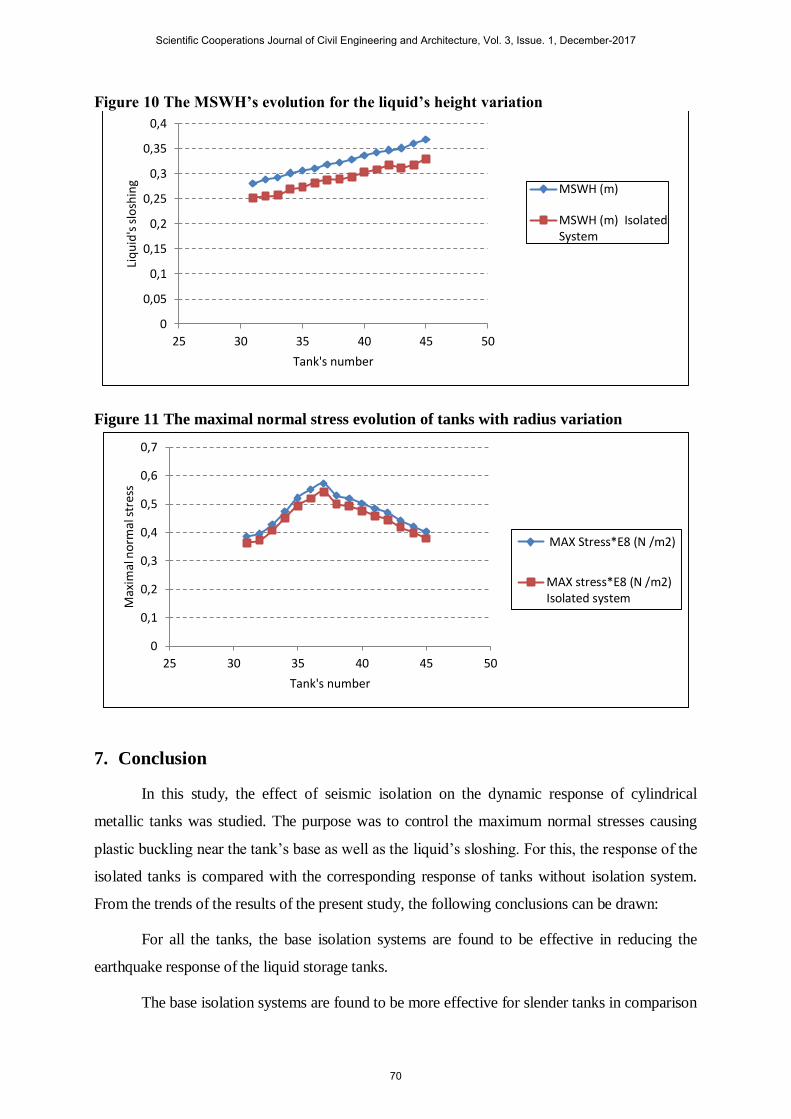
Figure 10 The MSWH’s evolution for the liquid’s height variation
Figure 11 The maximal normal stress evolution of tanks with radius variation
7. Conclusion
In this study, the effect of seismic isolation on the dynamic response of cylindrical
metallic tanks was studied. The purpose was to control the maximum normal stresses causing
plastic buckling near the tank’s base as well as the liquid’s sloshing. For this, the response of the
isolated tanks is compared with the corresponding response of tanks without isolation system.
From the trends of the results of the present study, the following conclusions can be drawn:
For all the tanks, the base isolation systems are found to be effective in reducing the
earthquake response of the liquid storage tanks.
The base isolation systems are found to be more effective for slender tanks in comparison
0
0,05
0,1
0,15
0,2
0,25
0,3
0,35
0,4
25 30 35 40 45 50
Liq
uid
's s
losh
ing
Tank's number
MSWH (m)
MSWH (m) IsolatedSystem
0
0,1
0,2
0,3
0,4
0,5
0,6
0,7
25 30 35 40 45 50
Max
imal
no
rmal
str
ess
Tank's number
MAX Stress*E8 (N /m2)
MAX stress*E8 (N /m2)Isolated system
Scientific Cooperations Journal of Civil Engineering and Architecture, Vol. 3, Issue. 1, December-2017
70
to broad tanks both for the sloshing and the elephant foot buckling.
The difference between the seismic response of the cylindrical metallic tanks under
seismic isolation and that of the embedded tanks without isolation decreases with the increase In
the dimensions of the tank .this is due to the insufficiency of the special bearings at the base of
this tanks.
References
[1] BOMHARD, H., STEMPNIEWSKI, L. LNG Tanks for seismically highly affected sites.
Intl. Post-Smirt Conference Seminar on Isolation. Capri, Italy, 1993. Energy Dissipation
and Control of Vibrations of Structures, vol. 115.
[2] RISTIC, D. Controlar structural behaviour and passive structural control. Üsküp, 1993.
Lectures for The International Post Graduate Studies, pp. 34-37.
[3] HOUSNER, G.W., HAROUN, M.A. Vibration tests of full scale liquid storage tanks.
California, 1979. Proc. and US National Conference on Earthquake Engineering,
Stanford, pp. 137-145.
[4] VELETSOS, A.S. Seismic response and design of liquid storage tanks. Guidelines for
the Design Of Oil and Gas Pipeline System. 1984. ASCE, pp. 255-370.
[5] KARABÖRK, T. Vibration control systems and high rubber bearing applications.
Sakarya, 2001. Unpublished Ph.D. Thesis, Sakarya University.
[6] CONSTANTINOU, M.C., KNEIFATI, M.C. Dynamic of soil-base-isolated-structure
systems. 1998. Journal of Structural Engineering, ASCE, vol. 114, pp. 211-221.
[7] JANGID, R., DATTA, T. Seismic behaviour of base isolated buildings: a state of art
review. 1985. Proceedings Civil Engineers Structures and Buildings, vol. 110, pp. 186-
203.
[8] KELLY, J.M. Base isolation: linear theory and design. 1990. Earthquake Spectra, vol.
6(2), pp. 223-244.
[9] NAEIM, F., KELLY, J.M. Design of seismic isolated structures. New York, 1999.
Computer Applications.
[10] JAISWAL, O.R., RAI, D.C., JAIN, S.K. 2004. Review of Code Provisions on Seismic
Analysis of Liquid Storage Tanks. Final Report: A - Earthquake Codes, IITK-GSDMA.
WANG, Y.P. Seismic Isolation of Rigid Cylindrical Tanks Using Friction Pendulum
Bearings. 2001. Earthquake Engineering and Structural Dynamics, vol. 30, pp. 1083-
1099.
Scientific Cooperations Journal of Civil Engineering and Architecture, Vol. 3, Issue. 1, December-2017
71