effort flow analysis: a methodology for directed product ... · 10 boothroyd, g and dewhurst, p...
TRANSCRIPT

1 Kalpakijia, S ManufacturingEngineering and TechnologyAddison-Wesley Publishing Co,New York (1992)
www.elsevier.com/locate/destud0142-694X $ - see front matterDesign Studies 25 (2004) 193–214doi:10.1016/j.destud.2003.09.002 193 2003 Elsevier Ltd All rights reserved Printed in Great Britain
Effort flow analysis: a methodologyfor directed product evolution
James L. Greer and Kristin L. Wood, Department of MechanicalEngineering, University of Texas, Austin, TX 78712-1063, USADaniel D. Jensen, Department of Engineering Mechanics, US Air ForceAcademy, Colorado Springs, CO 80840-6240, USA
Part count reduction through part combination is a recognized goal ofdesign for assembly (DFA). Some of the many benefits of part countreduction are: a reduced number of assembly operations, reducedprocurement costs, cycle time reduction, supply chain reduction, andhigher potential profits. In previous work, force flow analysis, a newtechnique to map forces as they flow across interfaces in a product, wasshown to be successful at systematically providing creative insights forpart combination. These insights arise by highlighting componentshaving no relative motion between them. This paper presents a novelconcept that extends the theoretical basis of force flow analysis to amuch broader scope, referred to as effort flow analysis, addressingcomponent combinations having varying degrees of relative motion. Asystematic method for classifying these sets of components is given, andcompliant mechanisms are presented as an example of successfulcombinations across interfaces with relative motion. Examples areprovided for the redesign of a ‘Quick Grip Clamp’ and a stapleremover, both of which highlight a specific class of relative motioncomponents. 2003 Elsevier Ltd. All rights reserved.
Keywords: design methods, product design, component combination,product modelling
Design for manufacturability (DFM) and design for assembly(DFA) can be considered sub-design processes that focus on spe-cific issues (manufacturability and assemblability) within a
design. In recent years, DFM has drawn considerable attention. Companieshave invested a great deal of effort and resources into new manufacturingtechniques, like gas-assisted injection molding, powder metallurgy, andlaser beam machining.[1] DFM software packages such as computer-aided

2 Ullman, David G The mech-anical Design Process, 3rdMcGraw-Hill Book Co, NewYork (1992)3 Dixon, J R and Poli, C Engin-eering Design and Design forManufacturing Field Stone Pub-lishers, Conway, MA (1995)4 Ulrich, Karl T and Eppinger,Steven D Product Design andDevelopment McGraw-Hill, Inc,New York (1994)5 Ettlie, J E and Bridges, W P‘Methods that work for integrat-ing design and manufacturing’ inManaging the Design-Manufac-turing Process, McGraw-HillBook Company, New York(1990)6 Otto, K and Wood, K L Pro-duct Design: Techniques inReverse Engineering and NewProduct Development PrenticeHall, NJ (2001)7 Tatikonda, Mohan V ‘Designfor assembly: a critical method-ology for product reengineeringand new product development’Production & Inventory Manage-ment Journal Vol 35 No 1stQuarter (1994) 31–388 Andreasen, Myrup M Designfor Assembly IFS Ltd, UK (1983)9 Boothroyd, G, Poli, C andMurck, L Automatic AssemblyMarcel Dekker, New York (1982)10 Boothroyd, G andDewhurst, P Product Design forAssembly McGraw-Hill Inc, NewYork (1989)11 Boothroyd, G, Dewhurst,P and Knight, W A ProductDesign for Manufacturing MarcelDekker, New York (1994)12 Poli, C, Graves, R andGroppetti, R ‘Rating productsfor ease of assembly’ MachineDesign August Vol 58 No 19(1986) 79–8413 Dieter, G E EngineeringDesign: A Materials and Pro-cessing Approach McGraw Hill,New York, NY (1991)14 Chow, W W Cost Reductionin Product Design Van NostrandReinhold Company, New York,NY (1978)15 Ishii, K, Juengel, C andEubanks, C F ‘Design for Pro-duct Variety: Key to Product LineStructuring’ in Proceedings ofASME DETC ‘95, Boston, MA(1995)16 Defazio, T L and Whitney,D E ‘Simplified generation ofmechanical assemblysequences’ IEEE Journal ofRobotics and Automation VolRA-3 No 6 (1987) 640–656
194 Design Studies Vol 25 No. 2 March 2004
process planning (CAPP)[1] have provided engineers with tools during thevarious design stages.[2–6]
Assembly techniques have also received emphasis, as the potential for con-siderable improvements in product assembly time, and associated profitmargins, have helped spread DFA interest into business entities.[7] Eventhough assembly typically accounts for between 40 and 60% of the overallproduction time,[8] it has not received the same type of attention as manu-facturing. Most of the progress in the assembly domain has come throughstudies of time and motion, division of work, and using robotics and auto-mation.
This trend does not imply that DFA methods are not prevalent. Boothroydand colleagues published their product design for assembly manual in1982.[9–11] This manual is regarded as the pioneering work of DFA tech-niques. It is composed of a formalized systematic approach that includesselection of the assembly method—manual, high-speed-automatic, orrobotic assembly—then an analysis of the assemblability of the designusing a design for assembly Worksheet. The worksheet (or associatedsoftware product) takes into account factors such as handling time, geo-metries, insertion time, and theoretical minimum number of parts to givean evaluation of the ‘design efficiency’ of the product. Besides Boothroydand Dewhurst, many other DFA techniques have contributed to the fieldand this research.[12–19]
Component combination is one DFA approach to improved assemblability.Component combination (or ‘piece count reduction’ ) is the combination ofonce separate parts into a single piece, which decreases the number ofparts that compose a product while maintaining the essential functionalityof the product. This piece count reduction in many cases is the most effec-tive means of improving assemblability. Fewer parts imply fewer oper-ations, less handling, and quicker assembly. Piece count reduction can alsohave broader implications. For example, Douglas Commercial Aircraft Co.ran simulations to determine what drives the cost of their commercial air-frame construction. They discovered that in addition to the costs ofassembly, the costs of fabrication, quality assurance, overhead-inventorylevels, tracking, and purchasing all depend on piece count.[20] Applicationof piece count reduction techniques is not without its detractors, and itmay be possible to go too far in combining components thus increasingthe complexity of the product and or assembly, and driving up costs.
Several authors have addressed the area of product complexity differentviewpoints.[21–23], Boothroyd et al.[11] proposed a set of DFA guidelines

17 Pine, J B, Victor, B andBoynton, A C ‘Making MassCustomization Work’ HarvardBusiness Review Sept.–Oct.(1993) 108–11918 Lee, S and Yi, C ‘Force-Based Reasoning in AssemblyPlanning’ ASME FlexibleAssembly Systems Vol DE-Vol73 (1994) 165–17219 Kim, G J and Bekey, G A‘Combining assembly planningwith redesign: an approach formore effective DFA’ in Proceed-ings of IEEE Conference onRobotics and Automation (1993)p 31920 Ashley, S ‘Cutting costsand time with DFMA’ MechanicalEngineering March 199521 Hinckley, Clifford M A Glo-bal Conformance Quality Model:A New Strategic Tool for Minim-izing Defects Caused By Vari-ation, Error, and ComplexityStanford University (1993)22 Fagade, A A and Kazmer,D ‘Optimal component consoli-dation in molded product design’in Proceedings of ASME DETCDTM, Las Vegas, NV, Sep-tember (1999) pp 255–26523 El-Haik, B and Yang, K‘Measures of Complexity inDesign’ in Proceedings of DETCDTM, Las Vegas, NV, Sep-tember (1999) pp 1–1124 Ananthasuresh, G K andKota S ‘Designing compliantmechanisms’ ASME MechanicalEngineering Nov. Vol 117 No 11(1995) 93–9625 Salamon, B A, and Midha,A ‘An introduction to mechanicaladvantage in compliant mech-anisms’ Journal of MechanicalDesign 120 June 120 (1998)311–315
195Effort flow analysis: a methodology for directed product evolution
Figure 1 Compliant pliers
(ComPlierTM)
for component combination. ‘… the theoretical minimum number of partsrepresents an ideal situation where separate parts are combined into a singlepart unless, as each part is added to the assembly, one of the followingcriteria is met:
(1) The part moves relative to all other parts already assembled duringthe normal operating mode of the final product. (Small motions whichcan be accommodated by elastic hinges do not qualify.)
(2) The part must be of a different material than, or must be isolated from,all other parts assembled (for insulation, electrical isolation, vibrationdamping, etc.).
(3) The part must be separate from all other assembled parts, otherwiseassembly, or parts meeting one of the above criteria would be pre-vented.’
These guidelines form a set of conditions that direct design efforts in partcombination, and are based on extensive studies of products and their cor-responding assembly processes.
While significant insight is gained from the DFA guidelines, it is proposedhere that the first of these guidelines is overly constraining. According tothe first guideline, interfacing components having relative motion arethought to be either un-combinable, or require significant redesign for suc-cessful combination. Recent ‘compliant’ mechanism examples bring newfocus to the possible combination of parts that experience relative motion.One proposal is that parts having relative motion can be combined intomonolithic mechanical devices using jointless compliant mechanisms.[24]
The ‘ComPlier ’ (Compliers Inc., Rolla, MO) is an example of a commer-cially available device of this type (Figure 1). The device is a plier designedand constructed using compliant joints in place of the traditional kinem-atic joints.[25]
The ComPlier compliant mechanism, molded as a single piece ofmaterial, replaces an assembly of multiple components that required rela-tive motion to perform the product function(s). In this case, significant

27 Lefever, D ‘Integratingdesign for assemblability tech-niques and reverse engineering’Master’s thesis, The Universityof Texas, Department of Mech-anical Engineering, 199528 Lefever, D and Wood, K‘Design for assembly techniquesin reverse engineering and rede-sign’ in Proceedings of ASMEDETC DTM ‘96, Irvine, CA(1996)29 Wood, K L and Otto, K L‘A reverse engineering and rede-sign methodology’ Research inEngineering Design Vol 10 No 4(1998) 226–24330 Harary, F Graph theoryAddison-Wesley, Reading, MA(1969)31 Tsai, L Mechanism Design:Enumeration of Kinematic Struc-tures According to Function CRCPress, Boca Raton, FL (2000)
196 Design Studies Vol 25 No. 2 March 2004
redesign effort and/or experience was needed to accomplish the part combi-nation as the design of this mechanism required a departure from the orig-inal spatial layout, or topology, of ‘components,’ of the multi-part device.However, it seems possible that certain parts of complex products could beredesigned using the original topology and geometric features by directlyreplacing certain components with a single compliant component. In thesecases, only minor shape modifications and material property issues need tobe considered to successfully accomplish the part combination. Therefore,techniques that aid in redesigning a product for piece count reduction areneeded. This paper presents a method for identifying this type of opport-unity through application of a technique known as effort flow analysis.Effort flow analysis is a systematic tool used to guide the designer towardpiece count reduction through part combination. The layout of the presentwork is first to review the origins of effort flow analysis, then show howeffort flow analysis can be used to identify creative opportunities for partcombination in complex assemblies where relative motion exists betweencomponents.
1 Background on effort flow analysis
1.1 Essential elementsEffort flow analysis encourages evolution in products from the mechanicalenergy domain by identifying component combination opportunities thatare achievable using rigid body and/or compliant mechanisms. Effort flowanalysis is the evolution of a technique originally known as force flowanalysis.[6,27–29] In order to be consistent with current and future researchefforts in this area, the term effort flow is used to replace the original termforce flow. The change in terminology from force to effort is the result ofa broadened research scope coupled with the fact that in the systems mode-ling domain, effort generally implies a broader class of physical phenom-enon than does force. Effort flow analysis uses an effort flow diagram torepresent the transfer of effort through product components. The effort flowdiagram is a semantic network composed of nodes and links that aredescribed using the fundamentals of graph theory.[30,31] The nodes of thediagram represent the components of the product, while the links representthe interfaces between the components.
Whenever possible, effort flow diagrams are laid out in such a manner thatthe general topology of the product is depicted in the topology of thediagram. As an example, an effort flow diagram for the Quick GripClamp product (Figure 2) is shown in Figure 3. The main benefit of mode-ling a product using an effort flow diagram is the exposure of possiblecomponent combination opportunities. These opportunities are made more

26 Jensen, D D et al. ‘Forceflow analysis: opportunities forcreative component combi-nation. Recent advances indesign for manufacture’ in Pro-ceedings of the ASME Inter-national Mechanical EngineeringCongress, Orlando FL (2000)
197Effort flow analysis: a methodology for directed product evolution
Figure 2 Schematic of the
Quick GripTM Clamp
Figure 3 Effort flow diagram for the Quick GripTM Clamp
obvious when the relative motion at the interfaces between connectedcomponents is characterized. Characterizing the relative motion entailslabeling the links between components. The links model the interactionbetween components, and are the conduit for effort flow (force or torquetransfer in the mechanical domain). Labels are added to the links to identifyrelative motion characteristics across the link. The labels on links betweenconnected components were previously defined as follows:[26]
‘N’ : no relative motion between components.‘R’ : relative motion at the interface and between other regions.
More explicitly, the ‘R’ label is used to denote an interface where ‘ relativemotion occurs both between the extents of connected components as wellas at the physical interface between the components (i.e. the nodes).’ Once

198 Design Studies Vol 25 No. 2 March 2004
characterization of relative motion and link labeling is completed, the fol-lowing guideline applies:[6,26–29]Effort flow guideline: groups of compo-nents where no relative motion exists (no R-Links connecting memberswithin the group) are candidates for combination if not prohibited bymaterial or assembly/disassembly issues. Combination between compo-nents or component groups that are connected by R-Links may be possible,
but will require more complex redesign.This guideline suggests therelationship between effort flow analysis and the DFM guidelines ofBoothroyd et al.[11] presented earlier, but goes a step further in suggestingthat parts that do experience relative motion may still be candidates forcombination. The next step in constructing an effort flow diagram is toidentify groups of components connected by non-relative motion links (N-Links). These groups of components are the starting point for further inves-tigation of component combination.
1.1.1 Example: effort flow analysis for the Quick GripClampA motivating example of effort flow analysis is given in this section andis used for comparison purposes as advancements to the method are intro-duced. The device modeled is a Quick GripTM Clamp (American ToolCompanies, Inc.). A schematic of the device is shown in Figure 2, whilethe effort flow diagram is given in Figure 3.
The clamp device works by applying pressure from the hand to the ‘Hand-le’ which ultimately closes the two ‘Pads’ on the object being clamped.Once the ‘Pads’ are clamped down on the object, they are constrained frommoving apart by friction and binding between the ‘Release Lever’ and the‘Slide Bar’ . In order to release the object, a force is applied to the ‘ReleaseLever’ in the direction illustrated by the ‘Release Force’ arrow. The forcepivots the ‘Release Lever’ in the ‘Swivel Notch’ and releases the frictionbetween the ‘Slide Bar’ and the ‘Release Lever.’ In order for the requiredfriction between the ‘Release Lever’ and the ‘Slide Bar’ to be maintainedduring clamping, the ‘Small Spring’ exerts a small force on the ‘ReleaseLever’ in the opposite direction from the ‘Release Force’ arrow. This‘Small Spring’ also provides a force to return the ‘Release Lever’ to itsclamping position (‘Release Lever’ rotated counter clockwise in the‘Swivel Notch’ ) after the clamp force is released.
The effort flow diagram for the Quick Grip (Figure 3) shows whichcomponents have relative motion between them, and which componentsdo not. A historical definition of relative motion is: motion between twoconnected components where that motion occurs either at the interface,

199Effort flow analysis: a methodology for directed product evolution
away from the interface, or both, during the operation(s) of a device.Analysis of the effort flow diagram and the operation of the clamp demon-strates an interesting phenomenon concerning relative motion. In the caseof the R-Links, relative motion occurs between the components withrespect to all points on them, including the interface. However, for thecomponents connected by the ‘?-Links’ in Figure 3, relative motion occursat all points, except the interface. For example, the figure shows that thelink connecting the ‘Small Spring’ and the ‘Release Lever’ is designatedwith a question mark. As represented by this link, the component motionis a combination of non-relative motion at the contact interface and relativemotion at all other points of the two components. For this example, theends of the springs do not experience relative motion with respect to theadjacent parts because they maintain non-sliding contact with those parts.However, the non-contacting portions of the springs do experience relativemotion with the adjacent parts during operation of the device. Analysis ofthe remaining ‘?-Links’ produces similar results.
The ‘?-Links’ for this case raise an important theoretical and pragmaticissue. The theory of effort flow analysis presented in Ref.[26] would notassign an R-Link label to the indeterminate links because, by definition,relative motion must exist at an interface to warrant an R-Link. Yet, forthe Quick Grip , the functionality of relative motion is apparent betweenthese components, just not at the interfaces. The fundamental insight fromthis analysis is that relative motion needs to be defined more precisely toobtain a better understanding of component combination possibilities.
Besides the need to refine our relative motion concept, careful inspectionof Figure 3 leads to another dilemma that is common to many productarchitectures, i.e. the presence of a high percentage of components withR-Links in the figure. If we seek to significantly affect part count in thisproduct, effort flow analysis must include techniques for combiningcomponents across R-Links. It is thus apparent that the DFM guidelinesof Boothroyd et al.[11] and the effort flow analysis guidelines presentedearlier are limited in their applicability and in need of extension. The nextsection treats this issue and others.
2 Theoretical advancements in effort flow analysis
2.1 The overall effort flow analysis methodologyThe overall effort flow analysis process is graphically represented by theflow chart shown in Figure 4, and is aligned with the product design frame-work presented in Ref.[6]. The process begins with establishment of theevolutionary goals of the design effort, the goals may be to incrementally

200 Design Studies Vol 25 No. 2 March 2004
Figure 4 Overall effort flow
analysis methodology dia-
gram
evolve the product or they may be to revolutionize the product. It shouldbe noted that the design effort could be to analyze an initial design forimprovement prior to a production decision, or to evolve a product underredesign. The process continues with the development of an activity dia-gram for the product. The activity diagram[6] provides an understanding of

201Effort flow analysis: a methodology for directed product evolution
the user operations that the product must carry out; these operations willbe modeled in the effort flow diagram. The next step in the process isfunctional modeling,[6] followed by product decomposition to establish theindividual components and their interfaces.
Finally, the components and interfaces of the product are modeled usingan effort flow diagram. This is where potential component combinationopportunities are identified. These opportunities become apparent duringcharacterization of the relative motion at the component interfaces. Inter-face characterizations; coupled with the structure of the graph, lead thedesigner to apply particular design evolution guidelines, which are classi-fied as first through Nth order. In order to determine when application ofa guideline leads to achievement of a successful component combination,a set of criteria are necessary.
2.2 Solid mechanics criteria for successful componentcombinationImplicit in the effort flow analysis methodology of Figure 4 is the assump-tion that any redesigned product must continue to satisfy the original pro-duct functions. In addition, fundamental physical laws must be satisfied.It is proposed that three fundamental functional criteria, based on funda-mental physical laws, form a set of necessary conditions for componentcombination in the mechanical energy domain.
The three solid-mechanics laws that form the basis for the fundamentalfunctional criteria, and are given as follows:
(1) Strain–displacement law,(2) Stress–strain law (material constitutive relationship),(3) Equations of equilibrium (force or stress).
These three laws are intrinsic to the physics of mechanical efforts and areinviolable in all cases, as they completely define the state of the materialin the product.
The necessary functional conditions proposed for component combinationare as follows:
(1) Degree-of-freedom condition: the original degree-of-freedom basedfunctions must be maintained in the resulting combined component,rigid or compliant.
(2) Energy transmission condition: the material of the combined compo-nent must satisfy the energy transmission functions required for theproduct.

32 Erdman, A G, Sandor, G Nand Kota, S Mechanism Design:Analysis and Synthesis, Vol 1,Prentice Hall, New Jersey (2001)33 Pahl, G and Beitz, WEngineering Design: A System-atic Approach Springer-Verlag,London (1989)
202 Design Studies Vol 25 No. 2 March 2004
(3) Actuation force condition: the actuation force of the resulting rigid orcompliant mechanism must be within the reasonable and achievablebounds of the actuating component.
These three functional conditions represent necessary, but not sufficient,conditions for component combination. Sufficiency is not achieved becausethe conditions do not capture the full spectrum of possible functionalrequirements. The relationship between the physical laws and the func-tional conditions is not one-to-one. Rather, the relationship is best rep-resented as a system of relationships that must be satisfied.
The degrees-of-freedom condition is based on the premise that if motionis provided in the original components, the motion-based function of thosecomponents must be preserved in the redesigned component. For mech-anisms, the motion has two fundamental requirements, the first is pathgeneration, and the second is end-point positioning.[32] The equilibrium andthe strain–displacement (especially for compliant mechanisms) laws arecritical in satisfying this condition.
The energy transmission condition is based on the concept of energy flowfrom functional modeling.[6,29,33] In the static or quasi-static mechanicalenergy domain model used in effort flow analysis, energy flow is rep-resented as either forces or torques. Based on this model, efforts will flowthrough the material of combined components derived from effort flowanalysis, and the material strength of these combined components must besufficient to provide the ‘ transmit energy’ function. This strength criterionnecessitates invocation and satisfaction of the stress–strain law.
The actuation force condition is a bounding relationship where the forcehas a minimum for sensitivity reasons and a maximum for achievabilityreasons. Equilibrium and strain displacement laws are again critical.
2.3 Importance of relative motionIt is stated in the DFM guidelines proposed by Boothroyd et al.[11] andagain in this work, that the absence of macro scale relative motion is amarker for component combination opportunities. It is proposed here thatthe existence of relative motion in varying degrees is the primary indicatorof component combination opportunities in effort flow analysis. Thishypothesis is supported by observations about the importance of relativemotion in both physical systems modeling (bond graphs based) and func-tional modeling.
In modeling energetic physical systems, power is the entity of primary

34 Karnopp, D C, Margolis, DL and Rosenberg, R C SystemsDynamics: A Unified Approach,2nd Wiley Interscience, NewYork, NY (1990)
203Effort flow analysis: a methodology for directed product evolution
interest. Power is the product of effort and flow, where effort equates toforce or torque, and flow equates to velocity, as described by power flowtheories such as bond graphs.[34] In functional modeling, the three flowsare energy, material, and information.[32] In the mechanical domain, mode-ling of the energy flow requires, at a minimum, the presence of a forceand may include a velocity as well. In representing the mechanical domainusing either the power flow of a bond graph or the energy flow of a func-tional model, the fundamental variables are force (or torque), and velocity.
Like power flow analysis and functional modeling, effort flow analysis inthe mechanical domain focuses on the flow of effort (force or torque)through the product of interest. The presence of effort in a mechanicalproduct is invariably accompanied by relative velocity between compo-nents during some aspect of product operation. The presence of effort isa fundamental requirement for effort flow analysis, while the presence ofrelative velocity is not. However, the presence of relative motion is criti-cally important from the standpoint of highlighting the locations of interest-ing interactions between components in the system.
Relative motion identifies locations within the product model where some-thing interesting is happening. Relative motion represents an easily ident-ifiable characteristic of the interaction between the components of the pro-duct, and provides a convenient classification scheme for components andinterfaces within the mechanical domain.
2.4 Basis set for relative motionAs evidenced by the ‘R-Links’ and ‘?-Links’ in Figure 3, there are severalways that relative motion can occur between components, and effort flowanalysis must be able to model each of them. To accomplish this modelingtask, we must first establish a fundamental understanding of the elementsthat make up effort flow analysis. The three fundamental physical elementsof an effort flow diagram are the components, the interfaces between thecomponents, and the forces transmitted between components at the inter-faces. Table 1 captures the permutations of possible relative motion with
Table 1 Table of relative motion permutations
Link type Relative motion location
Between interfaces Between components
N-Link 0 0C-Link 0 1R-Link 1 1I-Link 1 0
204 Design Studies Vol 25 No. 2 March 2004
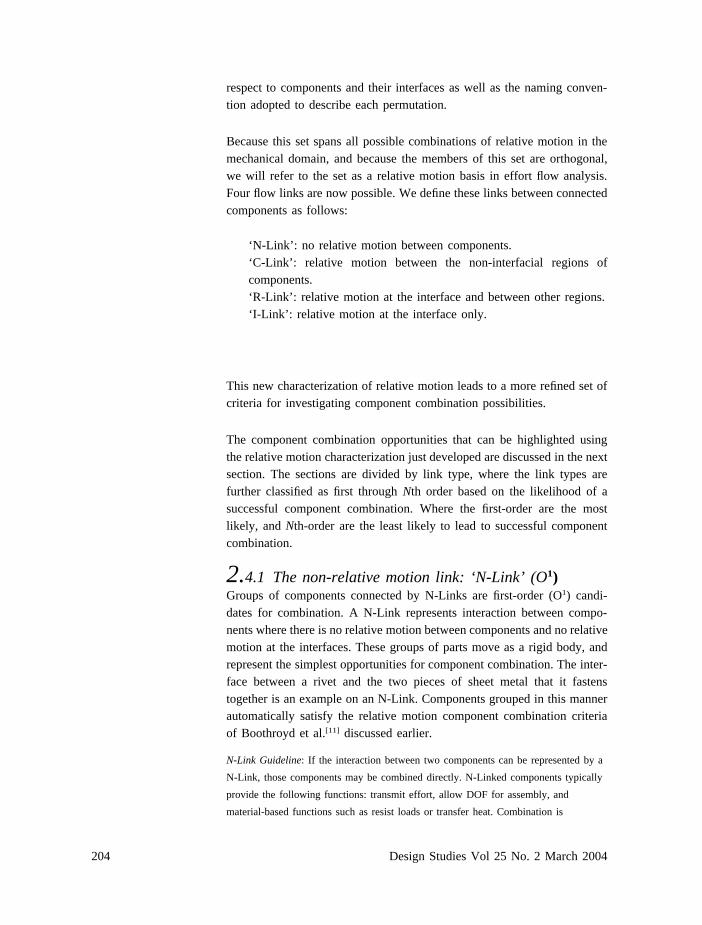
respect to components and their interfaces as well as the naming conven-tion adopted to describe each permutation.
Because this set spans all possible combinations of relative motion in themechanical domain, and because the members of this set are orthogonal,we will refer to the set as a relative motion basis in effort flow analysis.Four flow links are now possible. We define these links between connectedcomponents as follows:
‘N-Link’ : no relative motion between components.‘C-Link’ : relative motion between the non-interfacial regions ofcomponents.‘R-Link’ : relative motion at the interface and between other regions.‘ I-Link’ : relative motion at the interface only.
This new characterization of relative motion leads to a more refined set ofcriteria for investigating component combination possibilities.
The component combination opportunities that can be highlighted usingthe relative motion characterization just developed are discussed in the nextsection. The sections are divided by link type, where the link types arefurther classified as first through Nth order based on the likelihood of asuccessful component combination. Where the first-order are the mostlikely, and Nth-order are the least likely to lead to successful componentcombination.
2.4.1 The non-relative motion link: ‘N-Link’ (O1)Groups of components connected by N-Links are first-order (O1) candi-dates for combination. A N-Link represents interaction between compo-nents where there is no relative motion between components and no relativemotion at the interfaces. These groups of parts move as a rigid body, andrepresent the simplest opportunities for component combination. The inter-face between a rivet and the two pieces of sheet metal that it fastenstogether is an example on an N-Link. Components grouped in this mannerautomatically satisfy the relative motion component combination criteriaof Boothroyd et al.[11] discussed earlier.
N-Link Guideline: If the interaction between two components can be represented by a
N-Link, those components may be combined directly. N-Linked components typically
provide the following functions: transmit effort, allow DOF for assembly, and
material-based functions such as resist loads or transfer heat. Combination is

205Effort flow analysis: a methodology for directed product evolution
contingent upon the satisfaction of the material and assembly/disassembly functions.
Assuming these are satisfied, the primary performance function for the combined N-
Link component is to transmit effort.
Guideline support: groups of components connected by N-Links are classi-fied as first-order because they represent one of the fundamental tenets ofthe DFMA approach to component combination presented by Boothroydet al.[11] and espoused by many noted authors in the field of mechanicaldesign theory.[6,13,14,20,21] Application of the N-Link guideline provides thehighest likelihood of success with the least impact on product function andmechanical properties. This is true because, by definition, no relativemotion can exist across the N-Link. Hence, the N-Link guideline is appliedfirst before further effort flow analysis is carried out.
2.4.2 The component relative motion link: ‘C-Link’ (O2)Groups of components connected by C-Links are second-order (O2) candi-dates for combination. A C-Link represents interaction between compo-nents where there is relative motion between the non-interfacial regions butno relative motion at the interfaces. This interaction implies deformation ofone or more components as force is transmitted. The interface between acoil spring and the spring perch, or perches, on which it rests is an exampleof a C-Link. C-Links may represent either elastic or plastic behavior inthe interfacing components.
C-Link Guideline: If the interaction between two components can be represented by a
C-Link, those components can be combined directly into a compliant mechanism by
making parametric changes to the geometry of the components involved. C-Linked
components typically provide the following functions: transmit force, store/supply
energy, allow DOF, and material based functions such as secure solid and inhibit
energy.
Combination is contingent upon satisfaction of the material and assembly/disassembly
functions, as well as functional relationships to include the necessary deformation
and/or energy storage properties provided in the original product design. Assuming
these are satisfied, the primary performance functions for the combined C-Link
component is to allow DOF, transmit force, and store energy.
Guideline support: groups of components connected by C-Links are classi-fied as second-order (O2) candidates because they represent a reduced like-lihood for successful component combination when compared to the morefundamental approach of the N-Link combination. The presence of a C-Link implies that an intended relative motion function(s) exists in the orig-inal components. Component combination has the potential to impact thesedeformation based product function(s), and hence the likelihood of produc-

206 Design Studies Vol 25 No. 2 March 2004
ing a successful combination using compliant components is high, as com-pliance is used in the original design. However, satisfaction of the threenecessary functional conditions is typically more difficult to ensure simplydue to the presence of relative motion.
The integration of two parts connected by a C-Link necessitates that thematerial and/or geometry of the combined part have properties that providethe deformation/return functions originally performed by the separatedeformable part while providing the support functions of the interfacingsupport component. In addition to the deformation requirement, thematerial used in the combined component must have specific materialproperties related to other functional requirements such as color, creepresistance, conductivity, weight, etc. required in the original design. Thegreater the number of functional requirements, the greater the materialselection challenges become.
2.4.3 The relative motion link: ‘R-Link’(ON, Nth order)Groups of components connected by R-Links are Nth-order, three or higher(ON), candidates for combination. A R-Link represents general relativemotion occurring both at the interface and between the extents of thecomponents as force is transmitted. The hypothesis that R-Links are ‘com-binable’ only through significant redesign effort is modified here to reflectthe fact that the level of effort required to achieve component combinationacross some R-Links is not as significant as originally thought. R-Linkstake many forms to include: kinematic joints of all kinds, sliding contactin slots and guides, gears, and bearings. R-Links may also represent theinterface between a compliant member and a support member if that inter-face is not fixed.
R-Link Guideline: if the interaction between two components can be represented by a
R-Link, those components can be combined directly into a compliant mechanism
provided the original relative motion function can be provided through deformation of
the combined components. R-Linked components typically provide the following
functions: allow DOF and transmit force, and the primary material based function is
to regulate friction.
Combination is contingent upon satisfaction of the material and assembly/disassembly
functions, as well as functional relationships to include the necessary path generation
and end point positioning properties provided in the original product design.
Assuming these are satisfied, the primary performance functions for the combined R-
Link component is to allow DOF and to transmit force.
A first cut at synthesis of the combined component is to fuse the components using
their original material and geometry, then make parametric changes to refine the
combination.

207Effort flow analysis: a methodology for directed product evolution
Guideline support: groups of components connected by R-Links are classi-fied as Nth-order, three or higher (ON), candidates because they representthe least likelihood for successful component combination when comparedto the N-Link and C-Link combinations. In essence, the solid mechanicscriteria discussed above give the defining guidance on component combi-nation across R-Links. These criteria may be difficult to satisfy as themagnitude or spatial displacement of the relative motion increases.
2.4.4 The interface relative motion link: ‘I-Link’An I-Link represents relative motion at the interface only. No relativemotion exists within the extents, i.e. non-interfacial regions, of the compo-nents (Table 1). While clearly a member of the basis set, this link has notappeared in any of the products evaluated in our research, either concep-tually or within our empirical studies of products. For this reason, furtherdiscussion of the I-Link will be set-aside. As we study other energydomains, beyond mechanical, the I-Link type of relative motion maybecome apparent.
2.5 Product modeling using relative motion basis (O3 orhigher)The effort flow analysis advancements just discussed, combined with pre-vious work,[26] results in a method powerful enough to be applied early inthe design effort where significant impact can be achieved. Early appli-cation is possible because the information needed to use the method is nothighly detailed. At this point, an example is in order. To illustrate effortflow analysis, an example that exhibits all three classes of links known toexist in the mechanical domain is chosen.
The example is found in the Quick Grip Clamp (see Figure 2). An effortflow diagram, Figure 5, is constructed using the full relative motion basis.Note that the links previously labeled as ?-Links (those on both sides ofthe two springs and pads) in Figure 3 are now labeled with C-Links. Usingthe proposed extension of effort flow analysis, the ‘Small Spring’ is moreappropriately connected to both the ‘Release Lever’ and the ‘Housing’ bya C-Link, as are the interfaces for the pads and for the large spring.
Applying the C-Link guideline leads to the potential combination of the‘Front Grip Bar’ and ‘Pad #1,’ while application of the C-Link guidelineto the ‘Small Spring’ and either of its neighboring parts leads to a potentialcombination as well.
Assume that the decision is made to combine the ‘Small Spring’ with the‘Housing’ to produce a compliant region of the housing that satisfies the
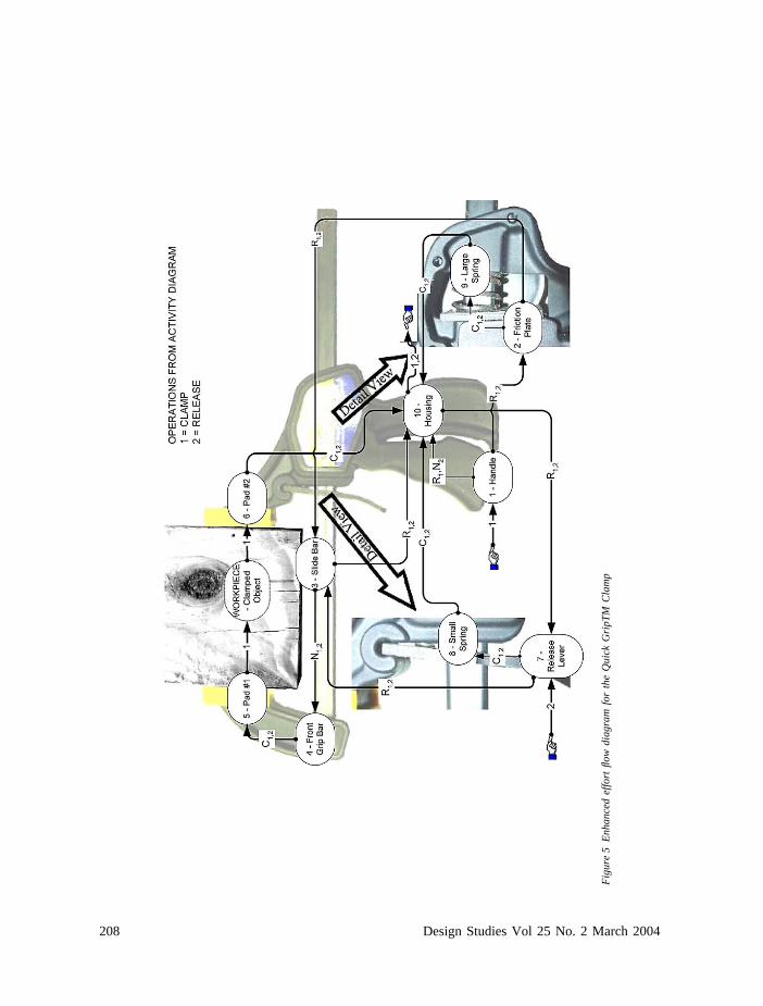
208 Design Studies Vol 25 No. 2 March 2004
Fig
ure
5E
nhan
ced
effo
rtflo
wdi
agra
mfo
rth
eQ
uick
Gri
pTM
Cla
mp

209Effort flow analysis: a methodology for directed product evolution
functional requirements of the spring. With this decision as the startingpoint, the solid mechanics criteria are now employed.
1. The position of the lever determines the position of the spring and theengagement of the lever with the bar. The motion of the lever is rotationabout the interface notch in the housing. The lever has a single DOF, andthat DOF must be maintained for product function reasons. By choosingto combine the spring and the housing, and not the spring and the lever,the DOF of the lever is unaffected by the combination.
2. The force transmission and strain energy storage functions of the springrelate to transmission of the finger force to the housing, and storage ofpotential energy to restore the release lever to its original position. Theseenergy transmission functions must be provided without causing materialfailure in the now combined spring/housing.
3. The actuating entity is the finger of the operator. The maximum humaneffort can be determined from anthropomorphic data. The minimum forceis determined by the amount of preload required to maintain sufficientfriction between the release lever and the slide bar to initiate locking duringthe clamping operation.
Satisfaction of these functional criteria will dictate that at a minimum thethree laws from solid mechanics (strain/displacement, constitutive, andequilibrium) be applied to the analysis of this combined component.Clearly there are material and geometry decisions to be made, the pointof this example is to show the power of these simple guidelines to highlightopportunities and give simple guidance for systematic evolution of the pro-duct. To determine the potential benefit of this combination, assembly andtooling costs, as well as issues of weight and aesthetics of the combinedpart would need to be evaluated.
2.6 Comprehensive exampleA more comprehensive example of product evolution through componentcombination is demonstrated for a staple remover product. The originalversion of the staple remover has ten parts as shown in Figure 6. The effortflow diagram for this product is shown superimposed on an image of theproduct in Figure 7. Using effort flow analysis, the part count may besignificantly reduced in the device. In fact, sequential application of thelink guidelines suggests that the device can be reduced to a single part.This piece count reduction process begins by combining the parts in group1 and in group 2 of Figure 7. As these groups contain only N-Links, partswithin the groups may be directly combined with no loss of relativemotion functions.

210 Design Studies Vol 25 No. 2 March 2004
Figure 6 Schematic for the
staple remover product
Figure 7 Effort flow dia-
gram for the staple remover
product
In terms of our extensions to effort flow analysis, the C-Links between thespring and its now combined neighbors lead to the application of the C-Link guideline to the C Group of Figure 8a. The result is the combinationof one of the arms with the spring to produce three components as shownin Figure 8b. Which arm is selected is immaterial due to the symmetry

211Effort flow analysis: a methodology for directed product evolution
Figure 8 Guideline appli-
cation sequence A–D
of the product. Continued application of the C-Link guideline pushes theevolution of the product (Figure 8a–c) to a point where only an R-Linkexists between the component and itself. This seems absurd at first, but amoment of reflection will result in one if not several concept variants fora monolithic product having relative motion at one interface with itself.The next step in the process is to apply the R-link guideline, the result ofwhich is the monolithic product modeled in Figure 9 and pictured in Figure10. At this point, one must evaluate the results against the desired outcome.
Does the product satisfy the three solid mechanics criteria? No, it doesnot. Assuming the geometry is not changed, and a material is chosen, aconflict arises. An elastomeric material is compliant enough to achieve thedeflection required but is too soft to satisfy the force transmission relation-ship at the interface with the staple (i.e. it does not possess sufficienthardness). A metal is strong enough to remove staples, but it is too stiffto be easily operated with the original geometry. For the device to be

35 Jepson, L J, Beaman, D,Bourell, B, Jackson, D, McAd-ams, J, Perez, J and Wood, K‘Multi-Material Selective LaserSintering: Empirical Studies andHardware Development’ in Pro-ceedings of the 2000 NSFDesign and Manufacturing Gran-tees Conference, Vancouver,Canada (2000)
212 Design Studies Vol 25 No. 2 March 2004
Figure 9 Effort flow dia-
gram for one piece stapler
Figure 10 Single-piece staple remover
completely functional as a single piece, a blended material would berequired. In a blended part, the hardness is attained at the tip of the clawwhile the required elasticity remains in the ‘ joint’ area, a multiple materialgraded system using solid freeform fabrication processes might be anotherpossibility.[35] In any case, there exists a conflict between two of the func-tional criteria.
To resolve this conflict, a step backward is taken, and a solution is achievedby separating the region of the product that must possess hardness (the tip)from the region that must be compliant (joint area A). To study this option,

213Effort flow analysis: a methodology for directed product evolution
Figure 11 Five-piece staple
remover with steel claws
a new staple remover with the original geometry is manufactured using arapid prototyping technique (e.g. selective laser sintering). The requiredmovement is very difficult to attain without rupture of the material, as thestresses are quite large in ‘Joint Area A’ of Figure 10a.
In order to reduce the high stresses, parametric changes in geometry aremade. These parametric variations, shown in Figure 10b, involve decreas-ing the quantity of material in the joint area, thus allowing the device tomaintain the needed movement of the claws while the stresses remain inthe elastic region. To achieve the hardness in the claw area, metal jawsare inserted into the compliant polymer body as shown in Figure 11. Thisoption increases the part count from one to five (body, 2-claws, 2-adhesivesbetween claw and body), representing in a 50% reduction in number ofparts from the original 10-piece system.
3 Summary and future pursuitsThe purpose of this work is two-fold: (1) to review earlier work on effortflow analysis,[6,26–29] and (2) to show how effort flow analysis may besystematically applied for directed product evolution using part combi-nation at interfaces where parts experience relative motion. As effort flowanalysis evolves, novel approaches become apparent for product redesign.In this work, effort flow diagrams are extended to include a relative motionbasis that includes four types of relative motion links, N, C, R, and I Links.The combination of parts connected via N-Links, C-Links, and R-Linksare discussed in the context of both rigid and compliant mechanisms.Finally, the inherent difficulty associated with part combinations is high-lighted across three classes of relative motion links. Examples of combin-

214 Design Studies Vol 25 No. 2 March 2004
ing parts are given for two current products, a Quick GripTM Clamp anda staple remover.
Future directions for this work include the development of a systematicmethodology that allows the designer to begin with one of two designgoals, evolution of the product, or revolution of the product. The path in themethodology is set depending on the stated goal. In addition, a systematicapproach for dealing with the conflicts that result when components arecombined across different material domains is under consideration. Finally,a method of identifying structures in the semantic network of the effortflow diagram that will lead directly to morphologies of the solution isunder development.
AcknowledgementsThe authors would like to express appreciation to the Air Force Office ofScientific Research, the Cullen Trust Endowed Professorship in Engineer-ing no. 1, and the June and Gene Gillis Foundation for their support ofthis research.