electric smelting at rustenburg platinum mines limited of nickel
TRANSCRIPT

Electric smelting at Rustenburg Platinum MinesLimited of nickel - copper concentratescontaining platinum-group metals
By J. C. MOSTERT* Pr. Eng.. B.Se. (Stellenboseh). M.Se. Met. Eng. (Fellow)and P. N. ROBERTSt Pr. Eng.. B.Sc. Eng. (Rand) (Fellow)
SYNOPSIS
The processes involved in the smelting in an electric furnace of nickel-copper concentrates containing platinum-group metals are described. These are concentrate drying, pelletizing, pellet drying, and flux and pellets proportion-ing, followed by smelting of the concentrate in a submersible-electrode electric furnace, which is discussed in moredetail. The furnace matte is blown in a converter to the white-metal stage and is cast in moulds, whilst the slag isgranulated, ground, and floated for recovery of valuable metals and afterwards pumped to the tailing dam.
SINOPSIS
Die prosesse betrokke by die smelting van nikkel-koper konsentrate, wat platina groep metale bevat, in 'n elek-triese oond word beskrywe. Hulle omvat konsentraat droging, konsentraat korrelvorming, korrel droging enproporsioneling van smeltmiddels en korrel konsentraat wat opgevolg word deur smelting van die konsentraat in'n elektriese oond met ondergedompelde elektrodes wat meer noukeuriger beskrywe word. Die rusteenkoper-nikkel van die oond word in 'n omsetter tot die witmetaal stadium geblaas en gegiet terwyl die slak gegranuleer,gemaal en gefloteer word vir die herwinning van metale, en daarna na die slikdamme gepomp word.
This paper was presented at themeeting of the PyrometallurgicalDivision of the American Instituteof Mining Engineers, and is publishedby courtesy of A.I.M.E.
INTRODUCTION
The Rustenburg Platinum Mines,Limited, Rustenburg Section (R.P.M.)is situated near the town of Rusten-burg in the Transvaal Province of theRepublic of South Africa. The ore-body lies in the Bushveld IgneousComplex, and the major economicmetal in the mineral deposit isplatinum, though the other platinum-group metals, nickel, copper, gold,and silver are also recovered. Ore istreated by gravity and flotation pro-cesses, and the flotation concentrateis smelted to a matte.
When the mine embarked on anexpansion programme for increasedproduction of platinum-group metals,it was necessary to decide whichtype of smelting should replace theblast-furnace smelti ng practised atthat time.
Not only was blast-furnace smelt-ing labour-intensive, but the priceof coke had risen steadily and therewas no room for further expansionat the site. Moreover, at that time
*Assistant Consulting Metallurgist, Jo-hannesburg Consolidated Investment Co.Limitedt Metallurgical Manager, RustenburgPlatinum Mines. Limited
290 APRIL 1973
the South African Government alsointroduced stringent antipollutionlaws. The emission of a very largevolume of gas containing betweenI and 2 per cent sulphur dioxidepresented a pollution problem thatwould be costly to solve and control.
The Consulting Metallurgists ofthe Johannesburg Consolidated In-vestment Company, the parent com-pany of R.P.M., therefore soughtalternative smelting methods. Rea-lizing that the R.P.M. concentratecontains a high percentage of mag-nesium, they immediately focusedtheir attention on electric smelting,where high operating temperaturescould be tolerated. A further at-traction was that power costs in theRepublic of South Africa are fairlyIow at about RO,OS per kW handthat the cost of power tends to risemore slowly than the cost of mostother commodities.
Eventually the Consulting Metal-lurgists recommended a 19,5 MV Arectangular electric furnace withsix in-line electrodes operating inpairs in a three-phase electricalsystem. They also recommendedthat pelletization of concentrates,followed by drying of the greenpellets, should be adopted to pre-pare the concentrate charge to thefurnace.
This recommendation was ap-proved by the Board early in 1967,
when planning of the new smeltercommenced. The plant was finallycommissioned in 1969.
TECHNOLOGY OF ELECTRICSMELTING
Electric smelting of sulphide oresas compared to reverberatory smdt-ing has been described in some detailby Dr Otto Bathl.
There is a similarity between thetwo smelting operations in the sensethat charges to both types of fur-naces are basically the same. Theshapes and sizes of the furnaces arealso similar in the rectangular form,although there has recently been amove towards circular electric fur-naces.
The main differences, however, liein the energy input and heat transfer,the formation and distribution ofmagnetite, and the roof construction.
Since the temperature above thecharge is relatively Iow in an electricfurnace as compared with a rever-beratory furnace, a sprung arch ofcheap firebricks as opposed to asuspended arch of expensive bricksis an obvious choice. The two mostvulnerable parts in a reverberatoryfurnace are the roof and the sidewalls at the slag line. In electricsmelting the strains on the roof andfurnace side walls have been elimi-nated by the difference in energyinput.
JOURNAL OF THE SOUTH AFRICAN INSTITUTE OF MINING AND METALLURGY

The heat required to smelt a chargein a reverberatory furnace is mostlygenerated from the combustion ofcoal, oil, or natural gas. The com-bustion flame travels through thefurnace with decreasing tempera-tures towards the slag end andleaves the furnace through the fluesystem. The charge is heated mainlythrough convection, but also bydirect impingement from the flameor indirect radiation from the roofat the burner end where the temp-erature is the highest. The transferof heat in a reverberatory furnace isfrom the top to the bottom zone, i.e.,from the flame to the charge to theslag and matte. The thermal effi-ciency in the reverberatory furnaceis therefore Iow - about 30 per cent(sum of the heat in the matte andslag, as well as the heat required forendothermic reactions, divided by theheat input) - as compared with thatof electric smelting, which is about60 per cent or higher.
The major heat source in an electricfurnace is from electrical energy andis produced in the slag by the elec-trical current according to the for-mula 12R.The heat produced in the
matte can be ignored because of thevery high conductivity of the matte.It is thus obvious that the slag musthave fairly Iow conductivity to pro-mote the usage of relatively highvoltage to avoid excessive amperage.Heat development efficiencies will bedependent on (a) the intensity of thecurrent, (b) the distance betweenelectrodes and between the elec-trodes and matte surface respectively,and (c) the specific resistivity of theslag. The specific resistivity of theslag is determined by the compo-sition of the slag, which in turn isdependent on the composition of theraw materials. Slag composition thusoffers an operational variable withineconomic limits. For high electricalefficiency it is advantageous to workat a high power factor, which in-volves changing of the other twovariables, viz, the current and thedistance through which the currentmust flow through the slag. Thecurrent normally flows through theliquid slag between a pair of elec-trodes (t to t of total energy) andbetween the tip of the electrode andsurface of the matte (the remainingt to i of total energy). Practicallimits in the design of the furnace
more or less determine the distancebetween electrodes, which leavesonly one operational variable, viz,the distance between the electrodesand the surface of the matte. Adeeper slag layer, higher voltage, andbetter power factor are thus theobjectives for efficient operation ofsubmerged-electrode slag-resistanceelectric furnaces.
The heat transfer in an electricfurnace is from the slag layer up anddown, Le., from the slag to thecharge and slag to matte, whichresults in electric-furnace matte beinghotter than reverberatory-furnacematte. There are no combustiongases in an electric furnace - onlygases formed by the reactions in thecharge.
Magnetite not reduced and fluxeddissolves in the matte and slag. In areverberatory furnace, the undis-solved magnetite settles on thefurnace bottom and forms accretions,mostly because of the lower temp-eratures and laminar flow of thematte and slag towards the slag-tapping end. In the electric furnace,matte and slag are both in turbulentmotion and, since the matte is at a
Plate I-Six in.line Soderberg-type electrodes for the 19,5 MV A electric furnace
JOURNAL OF THE SOUTH AFRICAN INSTITUTE OF MINING AND METALLURGY APRIL 1973 291
higher temperature, more magnetiteis dissolved in the matte. Themagnetite sometimes forms an inter-mediate zone of high viscosity be-tween the matte and slag layers.Magnetite layers or accretions canreadily be dissolved in an electricfurnace by lowering the voltage andbringing the electrodes nearer thematte surface, thus imparting extraheat into the matte at localized spots.Sometimes it is necessary to chargecoal and silica to these areas - anoperation that is not always success-ful.
ELECTRIC-FURNACE CON-STRUCTION AND PRINCIPLES
OF OPERATIONThe electric furnace as supplied to
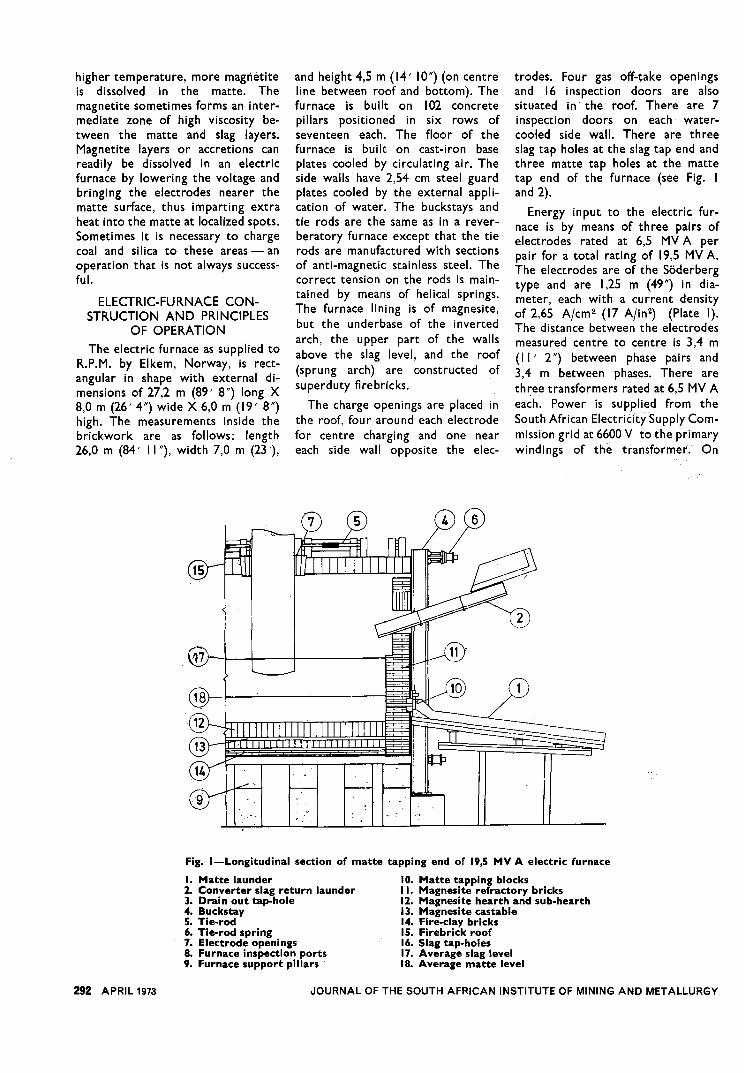
R.P.M. by Elkem, Norway, is rect-angular in shape with external di-mensions of 27,2 m (89' 8") long X8,0 m (26' 4") wide X 6,0 m (19' 8")high. The measurements inside thebrickwork are as follows: length26,0 m (84' 11"), width 7,0 m (23'),
and height 4,5 m (14' 10") (on centreline between roof and bottom). Thefurnace is built on 102 concretepillars positioned in six rows ofseventeen each. The floor of thefurnace is built on cast-iron baseplates cooled by circulating air. Theside walls have 2,54 cm steel guardplates cooled by the external appli-cation of water. The buckstays andtie rods are the same as in a rever-beratory furnace except that the tierods are manufactured with sectionsof anti-magnetic stainless steel. Thecorrect tension on the rods is main-tained by means of helical springs.The furnace lining is of magnesite,but the underbase of the invertedarch, the upper part of the wallsabove the slag level, and the roof(sprung arch) are constructed ofsuperduty firebricks.
The charge openings are placed inthe roof, four around each electrodefor centre charging and one neareach side wall opposite the elec-
trodes. Four gas off-take openingsand 16 ins~ection doors are alsosituated in the roof. There are 7inspection doors on each water-cooled side wall. There are threeslag tap holes at the slag tap end andthree matte tap holes at the mattetap end of the furnace (see Fig. Iand 2).
Energy input to the electric fur-nace is by means of three pairs ofelectrodes rated at 6,5 MVA perpair for a total rating of 19,5 MVA.The electrodes are of the Soderbergtype and are 1,25 m (49") in dia-meter, each with a current densityof 2,65 Ajcm2 (17 Ajin2) (Plate I).The distance between the electrodesmeasured centre to centre is 3,4 m(11' 2") between phase pairs and3,4 m between phases. There arethree transformers rated at 6,5 MVAeach. Power is supplied from theSouth African Electricity Supply Com-mission grid at 6600 V to the primarywindings of the transformer. On
@--
.2~
Fig. I-Longitudinal section of matte tapping end of 19,5 MV A electric furnace
I. Matte launder 10. Matte tapping blocks2. Converter slag return launder 11. Magnesite refractory bricks3. Drain out tap-hole 12. Magnesite hearth and sub-hearth4. Buckstay 13. Magnesite castable5. Tie-rod 14. Fire-clay bricks6. Tie-rod spring 15. Firebrick roof7. Electrode openings 16. Slag tap-holes8. Furnace inspection ports 17. Average slag level9. Furnace support pillars 18. Average matte level
292 APRIL 1973 JOURNAL OF THE SOUTH AFRICAN INSTITUTE OF MINING AND METALLURGY

,e,.c.'0'
@]
Fig. 2-Cross-section through 19,5 MV A electric furnace3. Drain out tap-hole 11. Magnesite refractory bricks4. Buckstay 12. Magnesite hearth and sub-hearth5. Tie-rod 13 Magnesite castable6. Tie-rod spring 14. Fire-clay bricks7. Electrode openings 15. Firebrick roof8. Furnace inspection ports 16. Slag tap-holes9. Furnace support pillars 17. Average slag level10. Matte tapping blocks 18. Average matte level
delta connection, the secondary volt-age of the transformer can be variedfrom 170 to 350 through seventeensteps by on-load tap changers. Themaximum electrode current is 32400A at transformer tap 4 or 20 I V(6,5 MVA). The current is carriedby copper bus bars and flexiblecables, which are connected to thesix contact pads by means of water-cooled copper pipes. The demineral-ized water not only serves as aheat-dissipating medium, but alsoexerts pressure of 70 kPa (40 Ibfin2)on the contact pads to secure goodelectrical contact. From the contactpads the current is carried by baked-carbon paste and flows through theliquid slag between electrodes, thetips of which are submerged in theslag to a depth of about 48 cm(19"), as well as between the elec-trode tips and matte layer. Owing tothe resistance of the slag, heat isgenerated in the slag and is trans-ferred to the charge by direct con-tact and convection.
The electrodes are loaded with
carbon-paste cylinders as illustratedin Fig. 3, which ensures that thepaste is well baked and all volatilesdriven off by the time electricalcontact is made. The electrodes areconsu med at a rate of about 13 cm(5") per day, and the electrodecasing is extended whenever re-quired by welding on I,75 m (69")sections to the top. Argon weldingis used to secure a solid weld free ofpinholes. Because the electrodes arecontinuously burnt away at thebottom, slipping of the electrodecasings through the holders bymeans of a grab-and-release pneu-matic-hydraulic combination systemis required. The slipping device con-sists of an upper and a lower ringconnected by four hydraulic jacks.The rings are cast steel with rubberdiaphragms in the inside. Duringslipping, the upper ring is deflatedand pushed up along the electrodecasing by 'means of the hydraulicjacks. The upper ring is then in-flated, the lower ring deflated, andthe electroqe casing pushed down
JOURNAL OF THE SOUTH AFRICAN INSTITUTE OF MINING AND METALLURGY
through the contact pads, the hy-draulic jacks being used to overcomethe friction of the contact pads. Thelower ring is inflated again and theprocess repeated automatically atfixed time intervals.
The power input through the threephases (three pairs of electrodes)is kept in balance automatically byregulating the depth of immersionof each individual electrode in theslag, and thus regulating voltage, bymeans of the two 24 cm (91") dia.hydraulic hoists per electrode. Thehoists have a maximum travel of1,22 m (4'), and are operated at5,86 MPa (850 Ibfin2) hydraulic pres-sure. The power input can be setmanually and controlled automati-cally at each desired setting. This isdone by means of instruments situ-ated in the control room.
Other instrumentation includespower-consumption meters, temp-eratu re recorders, furnace-d raftgauges, automatic slipping-deviceregulators, water-pressure and temp-erature Indicators, etc.
APRIL 1973 293

d
i19'
SLIPPINGCOLLARS
0
8'
TPRESSURE
RING
Fig. 3-Paste loading diagram to formula L = D - d = 5,8 m (19 ft), where L isthe correct length
SMELTING PRACTICE ATWATERVAL ELECTRIC SMELTING
PLANT - R.P.M.A flow diagram of Waterval Smelt-
ing Plant (Fig. 4) is included as abasis for the description of electricsmelting and its related operations.
Typical analyses of concentratesobtained from ore mined from theBushveld Igneous Complex are shownin Table I. The major gangue mineralsare pyroxene, plagioclase, feldspar,and biotite. The base-metal sulphide
minerals are chalcopyrite, pent-landite, and pyrrhotite. The platinum-group metals are either associatedwith the base-metal sulphides oroccur in the form of minerals such asbraggite, cooperite, laurite, or ferro-platinum. It is obvious that R.P.M.aims at the production of platinum-group metals at maximum recovery.The concentrate is thus a Iow-gradebase-metal concentrate by moststandards with a high MgO contentthat requires fairly high smelting
temperatures.Preparation of the charge
The concentrate is dried in Buttnerdryers from 21 per cent to about7 per cent moisture. The driers havea number of rotating hearths withfixed rabbles. The concentrate istop-fed and passesdownwards, whilehot air from coal-fired furnaces isdistributed uniformly through thedryer by a centrally located turbine.
The temperature and volume of thehot air are automatically controlled,
294 APRIL 1973 JOURNAL OF THE SOUTH AFRICAN INSTITUTE OF MINING AND METALLURGY

Concentrate (pellets) 110-150 3,5-4 2-2,3 15,0 8,5-10Furnace matte. . 500-600 16-18 9-11 38-42 26-28Converter matte. I 800-2 000 47-48 27-28 1-2 20-21Furnace slag 0,54 0,10 0,06 - 0,27
I
COt1CCntrca.e from wnMill
ru.....
~(x)NCENTR"'T1!
RECEIVINGBAV
~
FLUXR&CI!IIIING
."'t
TO
"""DUO' 0":::"""'
,
""'""'",UMu.~.
SOOOT,
"""."ATD:!l:-
ST""K
~8<.""A-
~ OU", TO ML' VOAnoc...
"'-v....I~
[..J'
~rrI, ",.~u.eND"pco\c.h ~...Illl. ~.L m
KALa .AW""",SK"
--
¥lA: ERVAL SMELTEA - FLOW DIAGRAM ,
Fig. 4-Flow diagram of Waterval smelter
TABLE I
TYPICALANALYSESOF CONCENTRATE AND FURNACE PRODUCTS
Material PGMg/t
Ni%
Cu%
Fe%
S%
~-
and gas is exhausted at Iow tempera-ture to the wet scrubbers.
The dried concentrate is disinte-grated to a fine powder and fed topelletizing pans of 3 m diameter.(Plate 2). The pellets are about1,5 cm (in) diameter, contain 10 percent moisture, and have a breakingstrength of 5 to 6 kg, although nobinding agent is used.
The green pellets are dried toabout 2 per cent moisture in oil-fired roto-Iouvre dryers. The driedpellets have a crushing strength of9 to 13 kg, and are transferred tostorage bins.
Fluxes, mostly limestone (94 percent CaCOa) and occasionally ironore, required to produce a suitableslag, and reverts, are crushed to
minus 1,91 cm CV) and stored in theirindividual bins. Pellets and fluxes areblended by a weight-proportioningsystem (Kukla weighers) and trans-ported to the electric furnace byconveyor belt and fed to the chargebins by means of shuttle conveyors.At present the charge consists ofpellets 76 per cent, limestone 22 percent, and reverts 2 per cent.Smelting
In the original planning, it was in-tended that wet concentrate shouldbe fed to the furnace. On this basis,the capacity of each 19,5 MVA fur-nace was estimated at 10000 tonnesof concentrate per month. Before theplant was erected, however, it wasdecided that the concentrate wouldbe pelletized. At an operating rate of
JOURNAL OF THE SOUTH AFRICAN INSTITUTE OF MINING AND METALLURGY
I
FeO%
I20
I
CaD
I
MgO% %
I
AI.O.
I
SiC.% %6
I
39
6 I 41
3 15
15 15
18,5 MW, a smelting rate of 12500tonnes of concentrate per month can
be maintained. The factor that mostinfluenced the 25 per cent increase insmelting rate is undoubtedly thepelletization of concentrates. Be-cause pelletization reduces flue-dust circulating loads, it permitssufficient draught to keep rooftemperatures within operationallimits, which are in the region of250°c. Pelletization also provides ameans of feeding a well-blendedporous charge to the furnace, whichallows reactions to proceed rapidlyand reaction gases to pass un-hindered to the atmosphere abovethe charge. Since the charge floats ontop of the slag, it completely coversthe slag to form an insulating medium
APRIL 1973 295

Plate 2-Pelletizing pans (3 m in diameter) forming about 1,5 cm diameter pellets
between the hot slag and the atmos-phere above the charge. This notonly promotes faster smelting of thecharge, but also protects the furnaceroof from direct heat and henceprevents excessive heat losses. Themixed charge can also be piled uparound the electrodes to stabilizethem, thus preventing drifting andswinging. Pelletization at R.P.M. is arelatively cheap operation and offersnumerous advantages.
The centre of the furnace is inter-mittently charged through four portsby means of pneumatically operatedchutes, which are manually con-trolled. The ports are situated aroundthe electrode. Two ports oppositeeach electrode, one for each sidewall, are operated on a choke feedfor side-wall protection above themolten-slag line. These side portsare self-feeding because of the natureof the charge, and so require nocontrol.
Molten converter slag is returnedby ladle to a cast-steel launder pro-jecting slightly into the furnacethrough the matte-tapping end wall.The converter slag, consisting mainlyof fayallte (2FeO.SiO2) with some
296 APRIL 1973
dissolved magnetite, has a higherconductivity than furnace slag, whichresults in a lowering of the voltagebetween the tips of the first pair ofelectrodes and the matte layer. Sincethe power input through the threepairs of electrodes is in balance andautomatically controlled, the firstpair of electrodes will automaticallybe raised to increase the voltagebetween them and the matte layer.This has a cooling effect on the matte.Magnetite tends to settle out fromthe slag to form a layer between theslag and the matte. This not onlyresults in the formation of accre-tions on the front wall, but alsotends to have a cooling effect on thematte, from which some magnetitesettles out on the bottom of thefurnace. The net effect is a bankformation against the front wall thatinterferes with matte tapping pro-cedures.
The problem has been overcomeby operating the first pair of elec-trodes on manual control whileconverter slag is returned. Thevoltage of the pair of electrodes isreduced by lowering the trans-former taps, and the electrodes are
manually lowered deeper into theslag bath until power input equal tothe input to any other pair of elec-trodes flows through the slag athigher amperage and lower voltage.Extra heat is thus supplied to thematte layer, preventing magnetitefrom settling out and favouring itsreaction with FeS; it is thus reducedto FeO which is slagged off as2FeO.SiO2. Care must be taken notto overheat the matte. Althoughthis procedure has been effective inthe control of magnetite build-up,the problem of magnetite build-upagainst the front wall would be lessif the converter slag were returnedby a cast-iron launder running ontop of the furnace roof and dis-charging the slag near the firstelectrode, as at Ronskar, Sweden.The slag return hole in the roof atRonskar is sealed off with a cast-ironball.
Furnace slag is continuously tappedat 1300-1380DC from one or twoof the three tap-holes, depending onslag production in the furnace. Thethree tap-holes are located at 1,56,1,76 and 1,96 m (62", 70" and 78")intervals above the furnace hearth
JOURNAL OF THE SOUTH AFRICAN INSTITUTE OF MINING AND METALLURGY

bottom; one is centrally positioned,and the other two are set at 1,44 m(4' 9") off centre. A slag level of2,1-2,3 m (82" to 90") is normallymaintained in the furnace, Le., ap-proximately 1,32-1,52 m (52"-60") ofslag on top of the matte layer, foroptimum smelting conditions. Witha slag level of 2,08 m (82") and amatte bath of 0,76 m (30"), theactual depth of the slag layer will be1,32 m (52 "). With an electrodeimmersion of 0,48 m (19"), thedistance between the tip of theelectrode and the slag-matte inter-face will be 0,84 m (33 "). The greaterthe distance between electrode tipand slag-matte interface, the greaterthe difference in the matte and slagtemperatures. This is an importantoperational factor in dealing withslags of high formation temperatures(1300-1400°C) in comparison withmattes of relatively Iow formationtemperatures (:t IOOO°C), especiallywhen the viscosity of the matte isIow at the slag formation tempera-tu re. The differences in slag andmatte formation temperatures arethus of vital importance in the designof furnace hearths and transformers.
It has also been noted that, in in-stances where the matte level ishigh-about 1,0 m (40")-and slaglevel Iow-about 1,8 m (70")- withdistances between the electrode tipand slagmatte interface of the orderof 0,28 m (11 "), submerged arcingoccurs and results in excessive turbu-lence around the electrodes, causingelectrical instability in the furnace.To rectify these conditions, thepower has to be reduced until theslag level is sufficiently raised or thematte level is lowered.
Disposal of slag
Furnace slag is tapped continuously,generally from the 1,76 m (70") levelspout. It is carried in a high-pressure-about 550 kPa (about 80 Ibjin2)-stream of water (water to slag 15:I byweight) into a Duplex Rake classifier,where it is further granulated, de-watered, and transferred to a beltconveyor feeding the slag grindingand flotation circuit. Typical slaganalyses are given in Table I.
The following factors influence theeffective granulation of slag by thedescribed method:(a) water to slag ratio,
(b) water pressure,(c) water temperature,(d) size, shape, and slope of launder,(e) smoothness of lining of launder,
and(f) speed of classifier rakes.
The granulated slag is milled inball mills in closed circuit withcyclone classifiers to about 60 percent minus 200 mesh. Overflow fromthe classifiers passes direct to a con-ventional flotation circuit, wheresome of the residual metal is re-covered. Flotation tailing is thick-ened and pumped to the concen-trator tailing sump for final disposalin the main tailing dam.
Tapping of matteA matte level of 59 to 76 cm (23"
to 30") (see Fig. 2) is maintained inthe furnace, and matte is tapped atregular intervals through one of twotap-holes situated 44 cm (19") abovethe furnace bottom 1,44 m (4' 9") oneither side of the furnace centreline. The third tap-hole is set at thefurnace centre line at the bottomof the furnace above the invertedarch to serve as an emergency drainhole. The original tap blocks werechrome refractory bricks of 35 X35X 15 cm (14"X 14"X6") with a3,8 cm (I f') dia. hole in the centre,held in position by steel wedgesattached to the main copper coolingjacket. These have been replacedsuccessfully by 60 per cent aluminabricks, which are less prone tocracking under the impact of themud gun. The refractories around thetap holes are watercooled by means
of copper jackets. Owing to thehigh pressure exerted by the matteand slag at the tap-holes, these mustbe closed by a clay gun. Typicalfurnace-operation data are presentedin Table 11.
Converting
The furnace matte (similar incomposition to that given in Table I)is tapped into 20-tonne capacitycast-steel ladles refractory lined. Thematte is transferred by 4O-tonneoverhead cranes to 3,05 m X 6, I m(10'dia.X20') long Pierce-Smithtype converters with 28 tuyeres of5 cm (2") dia. each. The tuyeres areautomatically punched using Ken-necott type 4B tuyere punchers. Anair blow of about 30-33 m3js (10000-II 000 ft3jmin) at 70-80 kPa (10 to12 Ibjin2) is maintained. The con-verters are lined with chrome mag-nesite bricks of South African manu-facture, which are consumed at arate of 35 kg per tonne of convertermatte produced.
Silica flux is weighed and added bymeans of a belt conveyor through aside spout to the converter. Thefree silica in the flux is controlled to65 per cent by reverts addition, andthe moisture content is kept below4 per cent. The temperature of therefractories is measured by opticalpyro mete rs and kept to below1300°C at all times. Typical con-verter-operation data are presentedin Table Ill.
About 14 tonnes of convertermatte is cast into cast-iron moulds atthe end of the blow. The converter
TABLE 11
TYPICAL FURNACE-OPERATION DATA
POWERLoad 18,5MWPower factor 0,98Consumed: per tonne of concentrate . . . . . . . . 897 kWh
pertonneofcharge. . . . . . . . . . . . . . 689kWhMATERIALS INPUT
Concentrate (pellets) 18t/hTotalcharge 23t/hConverter slag 90toIIOt/d
MATERIALS OUTPUTFurnace matte
"'" """""".4-5t/h
Furnace slag 2It/hTEMPERATURES
Furnace matte"""""""'"
.I 180°CFurnace slag 1350°C
RATIOSSlag:matteratio
""""'"
4.6:1Slag:concentrateratio 1,1:1Slag:granulationwaterratio 1:15
ELECTRODE-PASTE CONSUMPTIONPer tonne of concentrate 3,5kgPer tonne of charge
""""""""".2,7 kg
JOURNAL OF THE SOUTH AFRICAN INSTITUTE OF MINING AND METALLURGY APRIL 1973 297

TABLE III
TYPICAL CONVERTER-OPERATION DATA
Converter blows 2-3 per dayAverage cycle time
"'"5,26h
Average blowing time 3,82hFurnace matte, tons per blow. . . . . . . . . . . . . . . .. 44 tConverter matte, tonnes per blow. . . . . . . . . . . . . . 14tConverterslag,tonnes per blow. . . . . . . . . . . . . . . . . . . 45 tAirvolume
"""""""""""""'"30-33m3/s
Pressure 70-80kPa
matte (for typical analysis see Table I)is dumped from the moulds by cranes,crushed to minus I ", and bagged fordispatch to the matte refineries.The platinum-group metals followthe nickel and copper into the matte.The total recovery of platinum-group metals from the base-metalsulphides is about 99 per cent orbetter. The recoveries of copper andnickel from electric-furnace and con-verting operations are of the orderof 97 and 96 per cent respectively.
Disposal of exhaust gasesThe exhaust gases, 30 m3Js (60000
ft3Jmin) at 250°C and 88 kPa (26" Hg)from the furnace, and 34 m3Js(68000ft3Jmin) at 370°C and 88 kPa (26" Hg)from the converters, pass throughthe flue system, electrostatic pre-cipitators, and up a 183m (600 ,) stack
with an acid-resistant brick lining.This stack was recently erected toreplace the original two 61 m (200')stacks (Plate 3). Future plans in-clude sulphuric acid production fromthe S02 in the converter gases. Ofthe sulphur entering the smelter andconverter operations, some 60 percent leaves with the converter gasesvarying in S02 content from 2,5 percent to 6 per cent (for 70 per cent ofblowing time the S02 content ishigher than 4 per cent), 20 per centwith the furnace gases averaging0,4 per cent S02' 15 per cent with theconverter matte, and 5 per cent withthe furnace slag.
Recovery offlue dust
The flues are fitted with a series ofbottom outlet ports from which dustis removed. This dust, together with
that recovered from the precipi-tators, is washed down launders to acentral pump pit, from where it ispumped to a thickener. The thick-ened pulp is filtered and added to theflotation concentrate ahead of theBiittner dryers.
Heat balanceFurnace heat input can roughly be
divided into electrical energy 87 percent, converter slag 10 per cent, andcombustion heat of carbon elec-trodes 3 per cent. Furnace heat out-put can be divided into the follow-ing categories:
Furnace slag. . . . 49 per centEndothermic reactions 18 per centFurnace matte 7 per centFlue gases . . . . . 10percentRadiation and electri-
cal losses 16 per cent
ELECTRIC FURNACE - GENERALNOTES
Furnace start-up
The procedures adopted by R.P.M.for commissioning the electric fur-naces were to cover the hearth witha high-conductivity sacrificial liningof calcined dolomite with 40 per cent
Plate 3-Recently erected 183 m (600 ft) stack for combined furnaces and converter gases, replacing the two 61 m (200 ft)stacks
298 APRIL 1973 JOURNAL OF THE SOUTH AFRICAN INSTITUTE OF MINING AND METALLURGY

tar binder and to use electricalpower for heating the brickwork.The sacrificial lining was laid andtamped onto the hearth as close aspossible to start-up date to preventmoisture absorption.
Electrical contact was establishedby means of mild-steel cylindersfilled with crushed coke underneatheach electrode. Contact betweenelectrodes was established by crushedfurnace matte spread out on thebottom of the hearth on top of thelining. Dry granulated slag wascharged to the furnace level to thetop of the coke cylinders and bankedup along the side and end walls.With the transformers in star/deltaconnection and tap one (98, I V), thepower was switched on and theelectrodes lowered onto the coke bedtill electrical contact was made.
During the first week the elec-trodes were allowed to bake, vola-tiles were driven off, and heat wasgenerated to heat up the furnacebrickwork, especially the unpro-tected roof. Sufficient furnace draughtduring this period was thus essential.The coke underneath the electrodeswas replenished as required fromtime to time. The spring tension onthe rods was regularly checked andadjusted to allow even expansion ofthe brickwork.
As soon as the electrodes werebaked, the power was increased and
a molten bath of slag started to form.The furnace expanded rapidly duringthis period. As soon as charging ofthe furnaces with pellets and fluxescommenced, the resistance of theslag increased and higher voltage wasrequired. This necessitated the switchfrom star/delta transformer con-nection to delta/delta connection toenable personnel to operate thefurnaces at higher voltage.
Although the start-up was fairlysuccessful, it is generally felt that thesacrificial lining was not absolutelynecessary, especially since it liftedin places and restricted the matteflow. Because matte has a sub-stantially lower melting point thanslag, it should not have been used as aconductive medium. It would per-haps have been better to establishinitial electrical contact between theelectrodes by means of steel plates.This would have allowed the moltenslag to fill any cracks created by un-even expansion, thus sealing thebrickwork before matte was formed.
Furnace repairsThe refractory rings around the
electrodes were damaged by elec-trodes moving out of alignmentbecause of crust formations in thefurnace, poor charging operations,and defective valves on one of thetwo main hoists per electrode.Casting a ring of castable refractory
material instead of rebricking theserings prevented any further damageto the roof.
Apart from minor repairs to re-fractories around the matte tap-hole and complete rebricking of thematte end wall and partial rebrickingof the slag end wall after three yearsof successful operation, no otherserious drawbacks have been sufferedin the operation of the electricfurnace.
CONCLUSION
Not only has the electric furnacesuccessfully been adapted to theproduction of a copper-nickel mattecontaining platinum-group metals,but there has been a significant re-duction in operating costs. This,coupled with other advantages, hasestablished electric smelting of plati-num-bearing concentrates as an ob-vious choice for any future expansionprogramme.
ACKNOWLEDGEMENTS
The authors wish to thank theConsulting Engineer, RustenburgPlatinum Mines, Limited, for per-mission to publish this paper.
REFERENCEI. BATH, o. Electric smelting of sulphide ores,
Extractive metallurgy of copper, nickel and cobalt.pp. 241-286.
NATIONAL INSTITUTE FOR METALLURGYNASIONALE INSTITUUT VIR METALLURGIE
REPORT. VERSLAG
No. 1435
THE DETERMINATION OF CHROMIUM, MANGANESE, IRON, COBALT, AND NICKELBY ATOMIC-ABSORPTION SPECTROPHOTOMETRY USING THE NITROUS OXIDE
-ACETYLENE FLAME
16th August, 1972
Investigators: D. C. G. Pearton, R. C. Mallett
SYNOPSIS
The method developed (a detailed laboratory procedure is given as an appendix) is suitable for the determinationof the transition elements in ores and silicate materials.
The sample is dissolved in hydrofluoric, nitric, and perchloric acids, and the residue is fused with sodium per-oxide. Potassium nitrate is added as a de-ionizing agent, and the atomic absorption of the elements in solution ismeasured by use of a lean nitrous oxide-acetylene flame. There is no interference from the elements that are likelyto occur in ores and silicate materials, and the coefficient of variation of the method is less than 2 per cent.
JOURNAL OF THE SOUTH AFRICAN INSTITUTE OF MINING AND METALLURGY APRIL 1973 299