electrical network design handbook for wastewater ... · pdf fileelectrical network design...
TRANSCRIPT

1
Wastewater treatment plants Recommended electrical network design for efficient plant and energy operations**IEC standard compliance
222
Contents
Introduction ....................................................................................3
Electrical network design challenges on the rise for Wastewater Treatment Plants (WWTP) ...................................4
Key success factors for WWTP efficient electrical network design and architectures ...............................................................6
Recommended electrical network architectures proven and ready-to-go for WWTP .........................................................10
• Recommended architecture for small autonomous WWTP (T1) ............................................... 11
• Recommended architecture for medium-sized WWTP (T2) ..................................................... 12
• Recommended architecture for large WWTP (T3) .................................................................... 13
• Recommended architecture for large to very large WWTP (T4) ................................................ 15
• Recommended architecture for electrical power monitoring in all WWTP (T1, T2, T3, T4) ......................................................................................................18
Recommended features for WWTP ........................................... 21• Power quality ............................................................................................................................ 22
• Power factor correction ............................................................................................................ 24
• Motor management .................................................................................................................. 25
• Secure power supply ................................................................................................................ 33
• Power monitoring and control .................................................................................................. 36
• Energy efficiency technology .................................................................................................... 40
• Energy Management Information System ................................................................................. 41
Productivity software, tools and services ................................... 43
Commercial reference samples for designed and implemented electrical networks in WWTP (IEC & Nema) ................................................................................ 45

3
IntroductionWastewater Treatment Plants (WWTP) operators face major challengesWater.is.the.world’s.most.widely.consumed.product..Everywhere..it.is.a.strategic.resource..Everywhere.it.needs.to.be.carefully.stewarded..and.managed.to.meet.the.challenges.of:.•.access.to.clean.drinking.water.for.all,.•.water.pollution.and.sustainable.treatment,•..regulatory.and.environmental.issues,.even.more.stringent.(exacting.
standards.and.regulations.for.water.quality,.energy.conservation.and.reduced.waste.and.emissions).
WWTP.designers.and.operators.are.at.the.forefront.of.the.two.first.challenges..And.they.have.to.confront.these.challenges.on.a.fiercely.competitive,.cost-constrained.water.market..Labor.costs.are.rising..So.are.energy.costs.–.and.at.an.even.faster.rate..While.the.water.prices.remain.unchanged..
Electrical network designers have an important role to play for continuous quality and energy efficiency of wastewater treatmentWWTP.require.an.electrical.network.that.fits.in.with.their.continuous.quality.wastewater.processes.while.cutting.operating.costs.and,.in.particular.energy.costs..Therefore.a.plant’s.electrical.network.must.be.reliable,.easy.to.operate.and.maintain.throughout.the.plant’s.lifetime,.and.scalable.to.facilitate.future.expansion.and.process.overhauls..In.addition,.energy,.mainly.electricity,.accounts.for.up.to.30%.of.a.plant’s.operating.costs,.and.makes.the.plant’s.electrical.network.a.crucial.factor.for.cost.effective.wastewater.treatment.
Schneider Electric provides design recommendations, productivity tools and services to support efficient electrical network design, proven and ready-to-go for WWTPA.similar.and.consistent.approach.has.been.developed.by.Schneider.Electric.concerning.control.system.architectures,.for.the.design.and.build.of.integrated.power.and.control.solutions..Please.refer.to.the.dedicated.documents..The.recommendations.are.provided.for.structured.preliminary.and.final.design.which.helps.to.establish.suitable.configurations,.based.on.cost.effectiveness,.structural.efficiency,.fast.and.easy.implementation,.operational.performance.and.sustainability.criteria..It.describes.preferred.solution.architectures.by.plant.type.and.size..Each.solution.architecture.is.presented.with.a.single-line.diagram.for.medium.voltage.and.low-voltage.configurations,.key.design.principles,.and.the.recommended.equipment.and.technologies..
All.of.the.architectures.have.been.developed.to.meet.WWTP.performance.requirements.in.areas.like:•.Safety.of.people.and.property•.Compliance.with.codes,.regulations,.and.standards•.Availability,.operability,.and.maintainability•.Sustainability.and.energy.efficiency•.Scalability.and.retrofit.suitability•.Project.implementation.time.and.risk.mitigation•..Cost.–.in.particular.the.total.cost.of.ownership,.broken.down.into.capital.
expenditures.and.operating.expenses
Also.included.are.ways.to.reduce.both.design.and.operating.costs.over.the.entire.plant.lifetime.by.addressing.issues.like.power.quality,.motor.control,.secure.power,.power.monitoring.and.control,.and.energy.efficiency.
Last.but.not.least,.the.available.productivity.tools.and.services.support.electrical.network.designers.for.structured.preliminary.and.final.design,.for.specification.for.tender,.and.sometimes.up.to.design.implementation.and.electrical.network.modernization,.when.they.are.involved.

224
Electrical network design challenges on the rise for Wastewater Treatment Plants (WWTP)

5
Electrical.engineers.face.increasing.challenges.when.designing.systems..for.WWTP.
A rapidly-changing regulatory environmentToday’s.engineers.must.go.beyond.meeting.health.and.environmental.regulations—they.must.also.ensure.that.their.systems.will.be.compliant.with,..or.easily.upgradeable.to.potential.future.requirements.
The advent of new technologies When.it.comes.to.WWTP.design,.the.state.of.the.art.is.constantly.shifting.with.the.emergence.of.new.technologies.that.make.existing.processes.more.efficient.and.cost-effective—or.open.the.door.to.totally.new.ones.
Membrane-based.technology.is.one.such.example..It.improves.water.treatment,.but.uses.more.energy..Another.example.is.local.power.generation—whether.from.biogas,.heat.exchangers,.water.turbines,.or.solar.panels—which.can.reduce.a.plant’s.energy.consumption.and.carbon.footprint.
Finally,.advancements.in.information.and.communication.technology.are.paving.the.way.to.vastly.improved.WWTP.monitoring.and.control.systems.
An evolving energy market Increased.privatization.and.the.broad.implementation.of.smart.grids.have.rocked.today’s.increasingly.global.energy.industry,.making.both.plant.operations.and.decision-making.processes.more.complex.
Today’s.energy.market.is.also.being.shaped.by.demand/response,.an.approach.backed.by.local.government.officials.and.utilities..Demand/response.provides.an.opportunity.for.WWTP.to.play.a.key.role.in.streamlining.power.grid.operations.by.reducing.or.shifting.their.electricity.consumption.to.off-peak.hours.in.exchange.for.lower.utility.rates.and.other.financial.incentives.
The.technology.that.WWTP.use.to.improve.energy.efficiency.and.process.control.can.also.help.them.become.successful.contributors.to.demand/response.systems.by.enabling.them.to.coordinate.and.schedule.load.shedding.and.shifting,.so.as.to.reduce.energy.demand.during.peak.hours..
Electrical network design challenges on the rise for Wastewater Treatment Plants (WWTP)

226
Key success factors for WWTP efficient electrical network design and architectures

7
Performance of a standard compliant electrical network is key for continuous, safe, cost-effective and sustainable wastewater treatment services throughout a plant’s lifetimeThe.top.priority.for.a.WWTP’s.electrical.network.is.to.minimize.downtime.and.to.be.safe..Cost.effectiveness.throughout.the.plant’s.lifetime.is.next.in.line..A.WWTP’s.electrical.network.typically.accounts.for.5%.to.10%.of.the.total.plant.construction.cost..WWTPs.are.usually.permanent.facilities..The.average.WWTP.is.more.than.25.years.old,.up.to.50.years.in.some.countries.where.some.plants.have.been.operating.for.more.than.a.century..Therefore,.investing.in.high-quality.electrical.network,.equipment.and.wiring,.is.generally.cost.effective..The.electrical.network.design.process.should.be.iterative,.taking.into.account.the.overall.WWTP.design,.any.process-related.considerations,.overall.architecture,.equipment,.security,.and.HVAC..Finally,.electrical.network.specifications,.design,.installation,.and.commissioning.should.meet.all.applicable.codes,.regulations,.and.standards,.and.help.shorten.project.implementation.times,.plus.mitigate.risk.
WWTP electrical network designers will have to consider:Availability, operability, and maintainability
WWTPs.require.high.process.uptime,.which.necessitates.a.reliable.power.supply..To.achieve.this,.engineers.must:•..Choose.a.network.architecture.that.strikes.the.right.balance.between.risk.
mitigation.and.return.on.investment.(ROI)•.Select.reliable.equipment.configured.for.each.process.and.load•..Implement.an.appropriate.maintenance.policy.with.corrective,.preventive,.and.
predictive.measures•..Install.a.power.monitoring.and.control.system.with.the.following.features,.to.help.
operators.make.the.right.decisions.and.take.the.appropriate.corrective.actions:-.Real-time.monitoring.of.the.entire.electrical.network-.Alarming,.data.logging,.event.tracking,.fault.analysis,.and.root.cause.analysis-..Automatic.medium-voltage.loop.reconfiguration,.automatic.transfer.switch.
control,.and.automated.system.generator.testing-..Remote.troubleshooting.of.power.equipment.and.some.related.loads.like.motors
Operability.and.maintainability.have.become.more.crucial.than.ever.due.to.the.scarcity.of.skilled.workers.for.the.operation.and.maintenance.of.electrical.networks,.and.to.increasingly.complex.and.technology-driven.monitoring.and.control.systems.
Scalability and retrofit suitability
With.an.average.age.of.25.years,.most.WWTPs.have.clearly.been.designed.and.built.to.last..However,.plant.processes.and.equipment.change.over.time.to.allow.for.increased.capacity,.integrate.new.technology,.and.comply.with.new.regulations..Therefore,.a.plant’s.electrical.network.architecture.must.be.scalable,.compatible.with.third-party.equipment,.and.employ.standard.protocols.
For.new.plants,.it.is.important.to.ensure.that.equipment.and.systems.will.be.properly.maintained.and.upgraded.regularly.to.minimize.obsolescence.
For.plant.expansions,.new.electrical.networks.must.integrate.seamlessly.with.existing.equipment—with.minimal.effect.on.process.uptime..New.electrical.networks.should.also.meet.existing.criteria.for.reliability,.operability,.and.maintainability..
Plant.managers.should.make.sure.that.new.electrical.networks,.systems.and.equipment.receive.the.same.services.as.the.installed.base,.including.retrofit.services.
A WWTP’s electrical network typically accounts for 5% to 10% of the total plant construction cost.
Key success factors for WWTP efficient electrical network design and architectures

228
Safety of people and property
Above.all,.a.WWTPs’.electrical.network.must.be.safe..A.tested,.validated,.and.documented.architecture.is.an.excellent.way.to.ensure.system.safety..Next,.the.selected.equipment.should.be.standards-compliant,.backed.by.the.appropriate.certifications..Finally,.engineering.studies.on.issues.like.protection,.availability,.and.coordination.are.a.must..
And,.to.ensure.safe.operations.and.maintenance,.it.is.important.to.request.mechanical.and.electrical.interlocking.early.on.in.the.design.phase,.and.to.use.electrical.network.monitoring.and.control.features.like.alarming,.root.cause.analysis,.and.crisis.management.support—all.to.help.ensure.that.non-expert.operations.and.maintenance.staff.make.safe.decisions.
Cost
When.designing.electrical.networks.for.WWTPs—especially.for.design-and-build.projects—engineers.should.consider.the.total.cost.of.ownership.(TCO),.which.includes.capital.expenditures.(CapEx).and.operating.expenses.(OpEx).over.the.plant’s.entire.lifetime—25.years.on.average..A.WWTP’s.electrical.network.typically.accounts.for.5%.to.10%.of.the.total.plant.construction.cost.
Sustainability and energy efficiency
In.addition.to.the.many.water-related.environmental.issues.they.must.address,.WWTPs’.operators.are,.to.a.growing.extent,.seeking.sustainable,.energy.efficient.processes.with.low.CO2.and.other.pollutant.emissions..These.concerns.are.also.reflected.in.the.regulations.and.standards.with.which.WWTPs.must.comply..A.plant’s.electrical.network.must.be.designed.for.immediate.integration.with.energy.and.waste.monitoring.systems.
Compliance with codes, regulations, and standards
Electrical.network.designers.must.also.take.into.account.the.rapidly-changing.codes,.regulations,.and.standards.with.which.WWTPs.must.comply.in.order.to.ensure.public.health.and.safety.and.promote.sustainable.development.
Project implementation time and risk mitigation
Several.factors.can.help.shorten.project.implementation.times.and.mitigate.risk.
These.include:.•..tested,.validated,.and.documented.architectures.developed.specifically.for.
different.types.and.sizes.of.WWTPs•.productivity.enhancing.design.and.calculation.allowing.for.easy.comparisons•.careful.equipment.selection,.well-drafted.specification.for.tender.
It.is.also.important.to.factor.in.equipment.delivery,.installation,.commissioning,.and.modernization.times..
Energy consumption accounts for on average up to 30% of a WWTP operationg cost.
Key success factors for WWTP efficient electrical network design and architectures
9
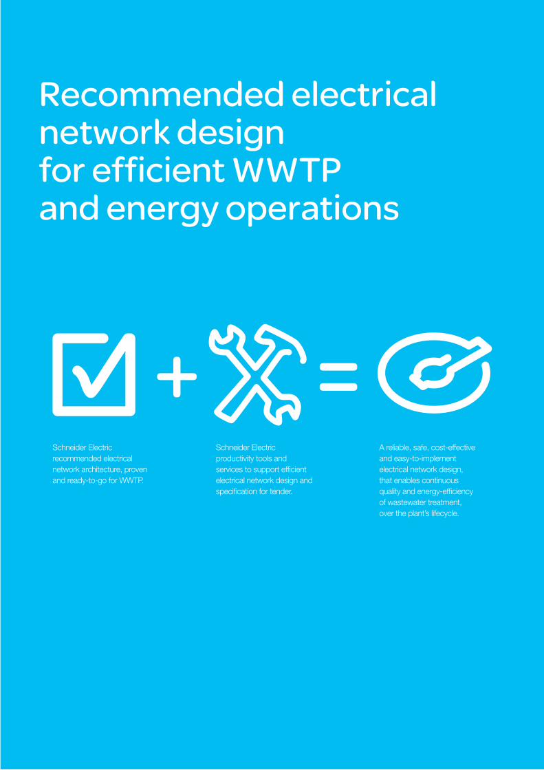
Recommended electrical network design for efficient WWTP and energy operations
+ =Schneider.Electric.recommended.electrical.network.architecture,.proven.and.ready-to-go.for.WWTP.
Schneider.Electric.productivity.tools.and.services.to.support.efficient.electrical.network.design.and.specification.for.tender...
A.reliable,.safe,.cost-effective.and.easy-to-implement.electrical.network.design,.that.enables.continuous.quality.and.energy-efficiency.of.wastewater.treatment,.over.the.plant’s.lifecycle.

2210
Recommended electrical network architectures proven and ready-to-go for WWTP
We have divided wastewater treatment plants into four sizes for the purposes of recommending the appropriate electrical network architecture. Plant size can be expressed in terms of the volume of water treated per day (m3) or the number of inhabitants served.
> T1: Small autonomous wastewater treatment
> T2: Small wastewater treatment plant
> T3: Medium-sized wastewater treatment plant
> T4: Large to very large wastewater treatment plant
The same segmentation applies also to control system architectures. Refer to dedicated documents.
T1 T2 T3 T4
m3/day 1,000.–.5,000 5,000.–.50,000 50,000.–.200,000 200,000.–.1,000,000
Inhabitants 1,000.–.10,000 10,000.–.100,000 100,000.–.500,000 500,000.–.1,000,000
Power demand
25.–.125.kVA 125.–.1250.kVA 1.25.–.5.mVA 5.–.25.mVA

11
ScopeWater treatment plants with power demand of less than 125 kVA, IEC.
Main design principles For T1 plants, the electrical network architecture must be simple and cost-effective while helping to reduce OpEx.
Because of the low power demand, we recommend a radial single feeder configuration with low-voltage power supplied by an electric utility.
In this configuration, all process units are supplied from a single low-voltage switchboard and motor control is performed using conventional wired systems (protection + thermal relay + contactor), variable speed drives and soft starters.
Power meter can be linked to local Remote Telemetry Unit (RTU), for transmission of power consumption and basic power quality indicators to remote control center.
Single line diagram
Recommended architecture for small autonomous WWTP (T1)
AbbreviationsMLVS: Main Low-Voltage SwitchboardVFD: Variable Frequency DriveSS: Soft StarterLV: Low-Voltage Motor
Recommended equipment
> Altivar™ 61/71 variable speed drives
> TeSys™ U motor starter or Altistart™ 22 or 48 soft starter for fixed-speed pumps
> Prisma™ Plus LV switchboard> PM700 power meters
Lifting, screening clarifier, aeration, sludge
Recommended electrical network architectures proven and ready-to-go for WWTP
2212
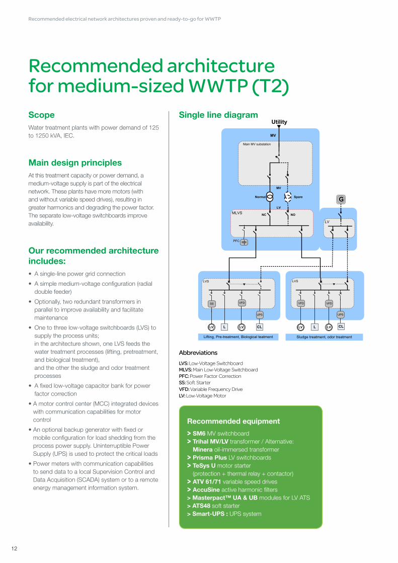
ScopeWater treatment plants with power demand of 125 to 1250 kVA, IEC.
Main design principlesAt this treatment capacity or power demand, a medium-voltage supply is part of the electrical network. These plants have more motors (with and without variable speed drives), resulting in greater harmonics and degrading the power factor. The separate low-voltage switchboards improve availability.
Our recommended architecture includes:• A single-line power grid connection
• A simple medium-voltage configuration (radial double feeder)
• Optionally, two redundant transformers in parallel to improve availability and facilitate maintenance
• One to three low-voltage switchboards (LVS) to supply the process units; in the architecture shown, one LVS feeds the water treatment processes (lifting, pretreatment, and biological treatment), and the other the sludge and odor treatment processes
• A fixed low-voltage capacitor bank for power factor correction
• A motor control center (MCC) integrated devices with communication capabilities for motor control
• An optional backup generator with fixed or mobile configuration for load shedding from the process power supply. Uninterruptible Power Supply (UPS) is used to protect the critical loads
• Power meters with communication capabilities to send data to a local Supervision Control and Data Acquisition (SCADA) system or to a remote energy management information system.
Recommended architecture for medium-sized WWTP (T2)
AbbreviationsLVS: Low-Voltage SwitchboardMLVS: Main Low-Voltage SwitchboardPFC: Power Factor CorrectionSS: Soft StarterVFD: Variable Frequency DriveLV: Low-Voltage Motor
Recommended equipment
> SM6 MV switchboard> Trihal MV/LV transformer / Alternative:
Minera oil-immersed transformer> Prisma Plus LV switchboards> TeSys U motor starter
(protection + thermal relay + contactor) > ATV 61/71 variable speed drives> AccuSine active harmonic filters> Masterpact™ UA & UB modules for LV ATS> ATS48 soft starter> Smart-UPS : UPS system
Single line diagram
Recommended electrical network architectures proven and ready-to-go for WWTP

13
Single line diagram: double radial architecture
Single Line Diagram : open medium-voltage loop
Recommended architecture for large WWTP (T3)
AbbreviationsAHF: Active Harmonic FilterIPMCC: Intelligent Power & Motor Control Center MLVS: Main Low Voltage SwitchboardPFC: Power Factor CorrectionVFD: Variable Frequency DriveSS: Soft Starter
• The radial single feed architecture is simpler and more cost effective but offers lower power availability.
• The open MV loop architecture is more suitable for larger plants and offers better availability.
Recommended electrical network architectures proven and ready-to-go for WWTP

2214
Scope Water treatment plants with power demand from 1.25 to 5 mVA, IEC.
Main design principles Plants of this size typically have high operating costs and a significant environmental impact due to the large volume of water they treat and their installed power. The medium-voltage (MV) electrical network—which extends down to the shop floor—should incorporate more redundancy. For optimal performance, power availability and monitoring should be managed with specific systems. Large plants like these contain many motors, which often use variable speed drives and thus need intelligent motor control systems.
We recommend a ring-main service from the plant’s electric utility to feed the MV system.
The primary MV switchboard should be located in a main electrical room to supply each workshop. Depending on the plant’s layout and local regulations and habits, we recommend either a radial single feed or an open MV loop architecture:
• The radial single feed architecture is simpler and more cost effective, but offers lower power availability.
• The open MV loop architecture is more suitable for larger plants and offers better availability.
Since MV/LV transformer failure can cause extended plant downtime—and in order to facilitate maintenance—we suggest either partial redundancy (to allow for downgraded operation in the event of a transformer failure) or total redundancy (to allow for normal operation in the event of a transformer failure). Installing several MV/LV transformers—preferably of equal power—as close as possible to the distributed loads can reduce the low-voltage (LV) connection distances.
Process units should be supplied by several LV switchboards.
Recommended features• Power factor correction can be managed by stepped capacitor banks, which
are suitable for large motors with fluctuating loads. Another option would be to provide power factor correction through a MV capacitor bank.
• Harmonic filters are recommended to improve power quality (since they mitigate variable speed drives disturbances).
• Given the large number of motors, we recommend motor control via an intelligent Power & Motor Control Center (iPMCC) to improve availability, facilitate maintenance, and limit operating costs.
• Power monitoring is also crucial to maintaining a plant’s overall energy efficiency. This can be achieved through power meters linked to an Energy Management Information System (EMIS), which could either be part of a Supervision Control and Data Acquisition (SCADA) system or a dedicated system with advanced features (for integration with multisite systems, for example).
• Backup generators should be used for critical process units. A mobile generator could be added for emergency backup. Uninterruptible Power Supply (UPS) is used to protect the critical loads.
Recommended equipment
> SM6 MV switchboard Alternative: RM6 ring main unit
(for harsh environments) Alternative: MCset MV switchgear
(for high short-circuit current)> Sepam MV protection relays> Trihal MV/LV transformer Alternative: Minera oil-immersed
transformer> Motorpact™ RVSS for MV motors> MotorSys™ Okken intelligent power
and motor control centers (iPMCC) Alternative: MotorSys Blokset IPMCC> VarSet capacitor banks> ATV 61/71 variable speed drives> ATS 100 for MV ATS> Masterpact UA & UB modules
for LV ATS> AccuSine active harmonic filters> Smart-UPS: UPS system
Alternative: MGE Galaxy> PM 700/800: power meter
Recommended electrical network architectures proven and ready-to-go for WWTP

15
Single line diagram: radial double feed
Single Line Diagram : open medium-voltage loopRecommanded architecture for large urban WWTP.
Recommended architecture for large to very large WWTP (T4)
• The open MV loop architecture is more suitable for larger plants since it limits cabling and infrastructure work; it can also be upgraded or expanded cheaper and more easily by “cutting” the loop and adding new loads.
AbbreviationsMLVS: Main Low-Voltage SwitchboardVFD: Variable Frequency Drive RVSS: Reduced Voltage Soft StarteriPMCC: intelligent Power And Motor Control CenterAF: Harmonic FilterPFC: Power Factor Correction
• The radial double feed electrical network architecture is simple and offers high power availability but is less suitable for extended sites.
Recommended electrical network architectures proven and ready-to-go for WWTP

2216
Scope Water treatment plants with power demand between 5 and 25 mVA, IEC.
Main design principles Plants of this size treat large volumes of water, which requires a large installed power base. Operating costs for these plants are high, and must be managed carefully.
The medium-voltage (MV) electrical network—distributed down to the shop floor—should incorporate a high level of redundancy. For optimal performance, power availability and energy efficiency have to be managed with specific systems. Large plants like these contain many motors, which often use variable speed drives (VSD), and thus need intelligent motor control systems.
We recommend a double supply service from the plant’s electric utility to feed the MV system.
Both architectures allow processes to be powered by a second supply in the event of a malfunction, ensuring service continuity.
The primary MV switchboard should be located in a main electrical room to supply each workshop. Depending on the plant’s layout and local regulations and habits, we recommend either a radial double feed or an open MV loop architecture:
• The radial double feed electrical network architecture is simple and offers high power availability, but is less suitable for extended sites.
• The open MV loop architecture is more suitable for larger plants since it limits cabling and infrastructure work; it can also be upgraded or expanded cheaper and more easily by “cutting” the loop and adding new loads.
The open MV loop architecture can also be controlled by an automatic reconfiguration system offering several benefits:
• Automated service recovery for enhanced personnel safety and maximum service continuity
• Fast, automated, and safe operation to minimize the risk of human error in stressful or new situations
• All network configuration scenarii taken into account
• Limited downtime during electrical fault elimination.
Since MV/LV transformer failure can cause extended downtime—and in order to facilitate maintenance—we suggest either partial redundancy (to allow for downgraded operation in the event of a transformer failure) or total redundancy (to allow for normal operation in the event of a transformer failure). Installing several MV/LV transformers—preferably of equal power—as close as possible to the distributed loads can reduce the low-voltage (LV) connection distances.
Each LV and MV switchboard busbar should be split into two half busbars linked with a bus tie. This configuration improves power availability by providing a dual supply, and lets maintenance be performed without stopping the process: one of the half busbars can be disconnected from the power supply while the other continues to supply the process. This configuration also improves operator safety since only limited maintenance is performed on powered equipment.
Recommended electrical network architectures proven and ready-to-go for WWTP

17
Recommended features• Power factor correction (PFC) can be managed by stepped capacitor
banks, which are suitable for large motors with fluctuating loads. Another option would be to provide PFC through a MV capacitor bank.
• We recommend harmonic filters to improve power quality (through the mitigation of VSD disturbances), which can be implemented in several ways:
- Compensation of several VSDs using a network compensation structure, based on one active filter per group of drives
- VSD (ATV61/71 plus) in combination with a dedicated multi-winding transformer using a 12-, 18-, or 24-pulse rectifier structure for very high power LV drives (>400 kW)
- A low harmonic drive system, based on active front end technology (ATV61 plus LH 55kW – 630kW)
• Given the number of LV motors, we recommend motor control via an iPMCC to improve availability, facilitate maintenance, and limit operating costs. The larger motors—such as high-power blower motors—can be supplied directly from the MV system and fitted with direct online, reduced voltage auto transformers, or reduced voltage soft start motor starters.
• Power monitoring is also crucial to maintaining the plant’s overall energy efficiency. This can be achieved through communicating devices or power meters linked to an Energy Management Information System (EMIS), which could either be part of a process SCADA system or a dedicated system with advanced features (for integration with multisite systems, for example).
• Power control can be provided through the process SCADA system, but for larger plants, a dedicated electrical SCADA would offer more advanced features, such as MV loop reconfiguration and automatic transfer sources.
• Backup generators should be conveniently connected to the MV system via MV/LV transformers, making it possible to distribute power over a large process area.
• If the sludge treatment process includes local power generation from biogas (co-generation using biogas generated from sludge digestion), the energy produced can be sold back to the grid or re-used within the plant.
Recommended equipment
> SM6 or GMA cubicles (depending on country)
Alternative: RM6 ring main unit (for harsh environments)
MCset or PIX MV switchgear (for high short-circuit currents)
> Sepam or Micom MV protection relays> Trihal MV/LV transformer and
Canalis™ KTA prefabricated busbar trunking, providing direct connection to Okken switchboards
Alternative: Minera oil-immersed transformer
> Motorpact RVSS for MV motors> MotorSys Okken intelligent power and
motor control centers (iPMCC) Alternative: MotorSys Blokset iPMCC> DVI••• MV capacitor banks> ATV 61/71 variable speed drives> AccuSine active harmonic filters
Recommended electrical network architectures proven and ready-to-go for WWTP

2218
Schneider Electric 7- Division - Name – Date
Energy Monitoring
Single line diagram
Recommended architecture for electrical power monitoring in all WWTP (T1, T2, T3, T4)
Ethernet TCP/IP Modbus RS486 Measurement
ACB: Air Circuit BreakerAHF: Active Harmonic FilterIMPR: intelligent Motor Protection RelayIPMCC: Intelligent Power And Motor Control CenterMCCB: Molded Case Circuit BreakerMLVS: Main Low-Voltage SwitchboardPFC: Power Factor CorrectionPMx: Power MeterRVSS: Reduced Voltage Soft StarterSEPAM: SEPAM protective relayUPS: Uninterruptible Power SupplyVSD: Variable Speed Drive
Note: Process automation controllers and their remote/distributed I/Os are not shown in this drawing.
LV Monitoring
Recommended electrical network architectures proven and ready-to-go for WWTP

19
An efficient metering architecture is crucial to both the Power Monitoring and Control System (PMCS) and the Energy Management Information System (EMIS).
ScopeAll WWTP. The metering architecture should be adjusted to plant size and needs.
The example shown page 18 is for a large to very large water treatment plant (T4).
Metering data are sent to three main control systemsIntelligent electrical devices—meters, switchboards, sensors, and other devices—serve as the primary data collectors. Data are sent to the PMCS, the EMIS, and the power control system. The intelligent electrical devices and the plant’s communications network determine how consistent, accurate, and reliable the data are.
Process, power, and energy-efficiency data are collected by intelligent electrical devices and sent to the various information systems.
Process control
A process is made up of many components, including motors; the process control system controls the motor starters. Generally, a process control system or distributed control system controls and monitors one or more processes.
Energy Management Information System
An EMIS is designed to facilitate decision making. The system aggregates data from intelligent electrical devices and sensors, and uses the data to generate tables, graphs, and reports.
Power control
Data collected by intelligent electrical devices can also be sent to a PMCS, which uses a power SCADA system with both basic and more advanced features. A PMCS typically covers the entire electrical network.
Recommended electrical network architectures proven and ready-to-go for WWTP

2220
Main design principles In the example shown, power measurement devices are located at the plant, process, and load levels. All of the equipment shown have communication capabilities and are linked to the plant’s communications network. Data collected by the devices can be integrated into a site-wide monitoring and control system.
In a MV system, measurement devices are typically located:
• At the point of delivery
• At the main processes (lifting, aeration, sludge treatment, odor treatment, and co-generation)
• At major loads (blowers).
MV protection relays are generally used to provide power measurements. They offer good accuracy and eliminate the need for additional current and voltage transformers to connect power meters to the network.
In a LV system, measurement devices are typically located:
• At the sub-process level (water line A, for example)
• At the load level.
In a LV system, several types of equipment—intelligent motor protection relays, variable frequency drives, circuit breakers, and active harmonic filters—can be used to provide power measurements. The use of intelligent devices (like CBs) incorporating metering and communication capabilities ensures that the right data are sent to the system. However, when better accuracy and advanced power quality analysis are required, we recommend using dedicated power meters.
Recommended equipment
> Sepam MV protection relays> ATV 61/71 variable speed drives> AccuSine active harmonic filters> Masterpact and Compact™ with
Micrologic™ Trip Unit circuit breakers> PM8xx series, PM7xx series,
and PM1200 power meters
Recommended electrical network architectures proven and ready-to-go for WWTP

21
Recommended features for WWTP

2222
Power qualityIntroduction
Power quality refers to both voltage and current quality determined according to criteria like magnitude, frequency, waveform, and symmetry. Disturbances to any of these factors are considered power quality problems, which can be of several types:• Harmonics (waveform)• Voltage sags and swells or voltage interruption (magnitude)• Voltage unbalance (symmetry)• Voltage frequency fluctuation.
Impacts and applications For WWTP, the main power quality issues are voltage interruptions and harmonics.
Voltage interruptions
For WWTP, long voltage interruptions may result in the discharge of untreated water into public waterways, creating a public health hazard and resulting in fines for the plant. Secure power equipment like generators and uninterruptible power supply systems can be used to ensure a continuous power supply.
Harmonics
WWTP also frequently encounter harmonics issues since variable speed drives account for a significant proportion of their total power. Harmonics can increase the RMS current in the different circuits and deteriorate supply voltage quality. Correcting harmonics can help:• Reduce overloading of the electrical system, thereby releasing useable
capacity• Lower system losses and demand power• Limit the risk of an outage and• Extend equipment lifetime.
Recommended features for WWTP

23
Recommended solutions This section treats the solutions for harmonic mitigation only. The solutions for voltage interruptions are treated in the Secure Power Supply section.
Harmonics can be corrected in several ways and in different levels of the electrical installation.
At the installation and/or equipment level, harmonics can be corrected by:• Passive filters, which consist of reactors and capacitors set up in a resonant
circuit configuration and tuned to the harmonic frequency; a system may be made up of a number of filters to eliminate several harmonic orders.
• Active filters, which comprise power electronics and are installed in parallel with the non-linear load, to compensate the harmonic current or voltage drawn by the load.
• Hybrid filters, which include a passive filter tuned to a given harmonic frequency and an active filter for the rest of the harmonics in a single unit.
At the equipment level only, harmonics can be corrected by:• Multi-pulse arrangement for variable speed drives; requires a dedicated
transformer directly supplied from the medium-voltage system. The standard configuration is based on a 3-winding transformer providing a 12-pulse supply for the drive. This limits harmonics considerably; no further mitigation is generally necessary.
• AC-line or DC-link chokes for drives (one for each drive), recommended when an installation includes many drives. The use of chokes increases drive lifetime and enables the use of cost-effective mitigation devices like active filters.
• An active front end, which is connected upstream to the standard frequency inverter and consists of three components: an active infeed converter; a line filter module; and a line filter choke. An active front end is the best-performing equipment-level harmonics-reduction solution, bringing THDi to under 4%.
Guidelines for choice of harmonics mitigation solution:• If harmonics mitigation is necessary, installation-wide mitigation should
be considered first, as one installation-wide device is usually more cost effective than several smaller devices installed at the equipment level.
• When large drives are used (≥400kW), local (equipment-level) mitigation is recommended. Typical mitigation techniques include multi-pulse configurations, active front end, and active filter systems.
• When a large number of drives are used, chokes are recommended (ACline or DC-link chokes).
• When PFC capacitors are used, detuned banks are preferable, with active filtering if further attenuation is needed. This will ensure capacitor protection and avoid resonance.
• When PFC capacitors are not used, an active filter is recommended.
Learn more: Harmonic Mitigation – Solution Handbook
Schneider Electric offers
> VarSet™ detuned capacitor banks and passive filters
> Active harmonic filters: AccuSine SWP and AccuSine PCS
> Hybrid filter: Custom design available on request
> Altivar ATV61 with optional active front end
> ATV212 range with anti-harmonics technology
Recommended features for WWTP

2224
Power factor correctionIntroduction
A plant’s power factor has a direct effect on its energy efficiency and electricity costs.
The power factor is the ratio of the real or active power flowing to a load divided by the apparent power in the circuit, and is a unitless number between 0 and 1. A power factor close to 1 means that the line current is at a minimum for the given active power.
Impacts and applicationsWWTP typically have a low power factor due to the many inductive devices they employ (like motors and transformers), meaning that power factor correction is often necessary.
Power factor correction consists of increasing a plant’s power factor so that it approaches 1, usually with a target of 0.92 to 0.95. Power factors lower than this may incur a surcharge by the electric utility supplying the plant.
Recommended solutionsPower factor correction is generally done by installing power factor correction capacitors that maintain a plant’s power factor above a value agreed upon with the electric utility. These capacitors also enhance the performance of some of a plant’s electrical system components such as cables and transformers.
At low voltages, compensation is provided by:• Fixed value capacitors, usually applied at motor terminals• Or automatically-controlled capacitor banks, connected for example to the
busbars of a general power distribution board.
In an electrical installation, compensation is performed using low-voltage capacitors, either for the entire installation, partially (section-by-section), locally (at each device), or some combination of the latter two. When the installed compensation power exceeds 800kvar and the load is continuous and stable, it is usually cheapest to install capacitor banks for medium voltages.
Learn more: Electrical installation guide
Schneider Electric offers> Medium-voltage equipment:
CP capacitor banks with Propivar™ NG capacitors
> Low-voltage equipment: VarSet range of fixed and automatic capacitor banks
Recommended features for WWTP

25
Motor managementIntroduction Motors constitute the primary power load of a WWTP and link a plant’s processes to its electrical network.
Today’s plants face new challenges to boost efficiency and increase their returns on both CapEx and OpEx. Intelligent motor starters (LV and MV) and motor control systems are one way to achieve this goal.
Impacts and applicationsBecause a single motor failure can mean costly downtime for a plant, plant managers need to ensure that their motors are adequately protected and have reliable control systems.
Although most motors are small and relatively cheap, a failure can mean lost production, increased maintenance costs, and a major risk if the process is critical. Therefore, better protected motors mean a better protected plant.
Motor protection and control is a plant-wide issue. It concerns not only a plant’s motors and processes but also operator safety, electrical technician safety (at the motor starter, electrical feed, and load levels via isolation and lockout), and the protection of the plant’s electrical network.
Recommended solutionsConventional motor protection systems based on thermal overload protection cannot communicate with higher-level process control systems and consequently fail to meet the needs of today’s continuous process industries.
This is due to several factors:
• First, motor failure can be triggered by a variety of incidents, such as an abnormal power load or supply, an insulation failure, incorrect wiring, or a number of external factors. Such incidents can cause motor burnout or other problems, each requiring a different response. Conventional motor protection systems with a “circuit breaker + contactor + thermal relay scheme protect only against short circuits and overloads—but these account for a mere 35% of motor failures. Therefore, conventional systems are clearly unable to ensure service continuity for critical processes.
• Second, protecting a motor by simply shutting it down is often impractical. Today’s plants need intelligent motor protection systems that can identify potential risks and alert operators to take action before a failure occurs.
• Third, motor protection systems must communicate with both process and power SCADA systems.
Motor protection and control systems must be able to send real-time data to control centers and receive the resulting commands. This data should be transferred via a commonly-used industrial communications protocol— such as Ethernet Modbus TCP/IP, Profibus-DP, DeviceNet, or Modbus—to ensure maximum interoperability with third-party plant control systems and equipment. That is, motor protection systems should be intelligent enough to get the right information to the right people at the right moment.
Recommended features for WWTP

2226
Intelligent motor protection and control systems can deliver an unprecedented amount of services to help operators diagnose problems and—for the first time—perform true preventive maintenance.• Protection fault counts• Motor control function counts• Fault history• Minimum wait times• Time to trip• Current maximum and start time of last start• Motor operating time
LV and MV motor starter solution
A motor starter has four basic functions:• Isolation• Short-circuit protection• On/off control • Overload protection.
Motor starters can be enhanced with additional features depending on the requirements of a particular motor.• Power features: speed adjustment, progressive starting, phase inversion, etc.• Control features: auxiliary contacts, time delay, communication, etc.
A motor starter can be designed in one of three different ways according to the desired function.
Motor starter design and functions
Isolator-fuse: short-circuit
protection, isolation for
maintenance.
Contactor: on/off
Overload relay: overload protection
Thermal-magnetic circuit breaker: short-circuit
protection, overload protection isolation for maintenance.
Contactor: on/off
Magnetic circuit breaker: short-circuit protection, isolation for maintenance.
Contactor: on/off, disconnection in case of fault.
Variable speed drive: progressive starting, variable speed control, motor protection, overload protection.
Motor Motor Motor
Recommended features for WWTP

27
There are several types of motor starters.
Main motor starter types (LV and MV)
Starting type Starting mode Description
Direct starting
1Direct on line
(DOL)
The simplest and least expensive starting mode, but can only be used if the load allows a large starting torque. Full voltage is applied directly to the motor; the starting current may be up to 10 times the nominal current (Is max #10 In).
2Star-delta starting
A simple and low-cost starting mode that reduces the current peak on starting. But the starting torque cannot exceed 1/3 of the nominal torque.The motor is started by coupling the windings in a star configuration under the line voltage (Is max #3 In).
Progressive starting
3Soft starting
A high-performance starting mode that allows soft starting and stopping with limited Is.The motor is fed a gradually increasing voltage according to the current and torque limit settings. Is max (#3 to #4 In) is set during starting, but this decreases torque performance.
4Variable speed drive
(VSD)
The most expensive and complicated mode, used for critical or specific loads like (conveyors or exhaust fans). In addition to the features offered by soft starting, VSDs allow continuous speed variation.
5Reverse motion
In addition to all starting mode the reverse motion is achieved 2 phases permutation (except VSDs where the controller handles both rotating directions).
For MV the functions are the same than for LV, but they are performed by specific units where each function is carried out in a separate cubicle or enclosure.
The starting mode names for MV motors are given in the following table.
Starting mode names for MV motor starters Correspondence to starting mode names for LV motor starters
Full voltage non-reverse (FVNR) Direct on Line (DOL)
Full voltagereverse motion (FVR) Direct on Line (DOL)+ reverse motion
Reduced voltage with reactance (RV) Soft starting (+ reverse motion)
Reduced voltage with autotransformer (RVAT) Soft starting (+ reverse motion)
Reduced voltage with soft starter (RVSS) Soft starting
MV drives Variable speed drive (VSD)
LV Intelligent Power and Motor Control Center (iPMCC)
An iPMCC is a system integrating Intelligent Motor Protection Relays (IMPR) into a reliable Power Control Center (PCC) and Motor Control Center (MCC) switchboard, while communicating with plant control systems through an industrial communications network.
Power circuit protection and control Circuit breakers for the protection,
control and isolation of LV DC loads and circuits.
Process automatisation PLC’s for process control with communication, diagnostic and data storage functions.
Motor motion control Variable speed drives and soft starters for effortless variable speed control offering extensive power, application and protection options for the entire installation (drive, motor, machine, environment).
Motor control and protection Relays, motor controllers and management systems.
Power consumption and quality mesasurement
Recommended features for WWTP

2228
iPMCC offer significant advantages over conventional systems in terms of plant design, construction, and operations.
iPMCC’s advantages throuhghout the plant’s lifecycle
Plant design and construction Better efficiency Shorter commissioning time
Less engineering work since starters are standardized over a wider range.
Less on-site wiring time due to the use of field buses.
Less set-up time due to remote configuration of motor control devices.
A better understanding of process reactions through detailed troubleshooting and statistics.
Faster troubleshooting and bug tracking.
Support for resolving process start-up problems.
Faster commissioning due to tested, validated, and documented architectures (TVDA).
Plant operations Greater service continuity Less unplanned downtime
More accurate sensors.
More accurate motor protection models.
Alarms giving operators time to fix the problem before the motor trips.
Detailed trip criteria to facilitate corrective actions.
Statistics for continuous improvement.
Records of all changes to protection configurations.
Operating costs Energy Maintenance Upgrades
Lower energy consumption.
Benchmarking and cost allocation.
Records of all changes to protection configurations.
Less downtime.
Faster troubleshooting and repair.
Less spare parts inventory.
Enhanced preventive maintenance strategy.
Simplified engineering.
No wiring required.
Easier setup.
Easier process tuning and commissioning.
Recommended features for WWTP

29
Description of iPMCC’s components
Intelligent motor protection relay (IMPR)An intelligent motor protection relay—the key component of an iPMCC—is an electronic device with a microprocessor inside. It protects motors using current and voltage calculations; the device receives data from sensors and calculates potential motor faults and operator risks.
IMPRs can detect many kinds of faults. They are much more effective than conventional thermal relay protection systems, and can incorporate many complementary functions like monitoring, alarms, fault recording, statistics, and communications.
LV motor control center (MCC)A LV motor control center (MCC) is an electrical switchboard that centralizes all motor starters of a given process. Many industries prefer such centralized control systems to facilitate operations and maintenance.
Critical applications typically employ withdrawable MCC functional units since they allow for easier repair in the event of fault; the faulty motor starter can be replaced quickly without locking out the entire switchboard. Less critical applications usually employ fixed or disconnectable functional units. MCC installation systems should type-tested assemblies (TTAs) to ensure the applications’ safety and reliability. Type testing, especially rising temperature testing, is essential in iPMCC applications because the IMPRs in iPMCCs are more heat sensitive. Furthermore, MCCs should provide a reliable bus communications connection.MCCs are different from multi-purpose cabinets, which can group only a few motor starters. They have few electrical features and do not allow for separation between motor starters’ functional units. Multi-purpose cabinets must be completely locked out to perform any starter maintenance or reconfiguration
Communications capabilities
iPMCC applications, typically comprising 50 to 1,000 motor starters, must process large amounts of data including motor status, current value, and any alarms. Conventional wire-to-wire connections are neither efficient nor cost-effective when a great deal of data must be transmitted. Today such data is usually transferred via a communications network.
Such communications networks need the support of a common language, which is the communications protocol. The following chart shows the protocols most commonly used in different levels of industrial communications networks.
Recommended features for WWTP

2230
Schneider Electric’s offersLV motor starters
MV motor starters
Correspondence to starting mode names for LV motor starters
Schneider Electric offerst
Direct on Line (DOL)Compact / Masterpact circuit breakers
LD…thermal relaysLC…contactors
Star- delta startingCompact / Masterpact circuit breakers
LD…thermal relaysLC…contactors
Soft startingCompact / Masterpact circuit breakers
ATS 48, ATS 22
Variable speed drive (VSD)Compact / Masterpact circuit breakers
ATV 61 /71
Starting mode names for MV motor starters
Correspondence to starting mode names for LV motor starters
Schneider Electric offers
Full voltage non-reverse (FVNR) Direct on Line (DOL)MCset, MV switchgear
(for high short-circuit current)
Full voltagereverse motion (FVR) Direct on Line (DOL)+ reverse motionMCset, MV switchgear
(for high short-circuit current)
Reduced voltage with reactance (RV) Soft starting (+ reverse motion) Motorpact RV
Reduced voltage with autotransformer (RVAT) Soft starting (+ reverse motion) Motorpact RVAT
Reduced voltage with soft starter (RVSS) Soft starting Motorpact RVSS
MV drives Variable speed drive (VSD) Altivar ATV 1000, ATV 1100
Recommended features for WWTP

31
iPMCC: MotorSys
MotorSys is Schneider Electric’s flagship motor control system, available in three models according to the desired size and cost-effectiveness.
MCC and iPMCC positioning for WWTP
WWTPT1 T2 T3 T4
MotorSys High Dependability iPMCC
++ +++
MotorSys Easy iPMCC ++ +++
Conventional MCC + +
Model 1: Conventional MCC for WWTP T1
This basic system uses conventional overload relays. It is the cheapest system and boasts a very large installed base. However its operational costs rise as the number of motors involved increases, making it less cost-effective for larger applications.
Model 2: MotorSys Easy iPMCC
The Easy iPMCC system targets small- and medium-sized applications. Its main benefits are its reasonable overall cost and ease of installation, commissioning, and maintenance. The following diagram shows a PlantStruxure system architecture with several functional units, including the MotorSys Easy iPMCC for motor control.
Architecture with MotorSys Easy iPMCC
Recommended features for WWTP

2232
Model 3: MotorSys High Dependability IPMCC
The High Dependability iPMCC uses Ethernet-down-to-the-device technology. The main benefits of this system are:
• The ability to provide different levels of reliability according to a plant’s needs, with a view to building an architecture with “no single point of failure” for motor control
• Maximum transparency for a high added-value service
• An open architecture due to the use of Ethernet throughout the system.
The following diagram shows a PlantStruxure system architecture with several functional units, including the MotorSys High Dependability iPMCC. A high availability PlantStruxure automation system with a dual Ethernet ring can be used to connect all functional units in the architecture to the control room. Ethernet allows for a wide array of network architectures, ensuring a high degree of flexibility
Architecture with MotorSys High Dependability MCC
Recommended features for WWTP

33
Secure power supply Reliable power is essential to wastewater treatment plants so they can comply with environmental regulations and avoid costly contamination.
Back-up generators and uninterruptible power supply (UPS) protection—combined with dependable power architecture and intelligent power monitoring systems—lets plants keep their equipment running, protect against data loss, and ensure data transfer among critical systems.
With a secure power supply at every step in a wastewater treatment process, critical systems can be kept running safely for reliable 24-hour plant operation.
Uninterruptible power supply (UPS)
IntroductionUPS systems are designed to protect critical loads from power variations and outages.
• Batteries supply the power in a UPS system, which prevents a total interruption but only for a limited time: from several minutes to several hours. Therefore, these systems are typically combined with a backup generator to ensure a continuous power supply, especially when a power interruption could have serious consequences. A UPS system’s back-up time should be compatible with the time needed for the back-up generator to start-up and be brought on line.
• UPS systems are also used to supply power to loads that are sensitive to disturbances by generating a “clean” voltage that is independent of the grid.
Impacts and applicationsSecure power via a UPS system is essential at several levels of a plant’s operations.
• At a process level, to prevent the loss of control over critical processes at pumping stations or treatment units. This typically comprises the following critical loads, located in an electrical room or the plant itself:- Communications equipment- Process controllers and downstream remote I/O boards- Process monitoring instruments, intelligent electronic devices, and local control stations- Security systems (fire, access control, and video).
The usual required back-up power time is 30 min., although longer times may be needed in certain circumstances.
• At a control room level, to prevent data loss and server shutdown. This typically comprises servers, workstations, and communications equipment, with configurations ranging from a standalone server rack to a complete server room requiring cooling services and management.
• Other critical loadsOther equipment can be protected by a UPS system, such as: - Ultraviolet (UV) water disinfection systems, due to their sensitivity to variations
in power quality- Inlet valves.
Recommended features for WWTP

2234
Recommended solutions
Technology
Double conversion on-line technology is recommended for the sensitive loads and harsh power conditions typical of water treatment applications. This technology provides excellent voltage conditioning (output voltage and frequency are independent of input voltage and frequency) and easy paralleling. The on-line operation means there is no transfer time during an AC input power failure, since the AC input charges the back-up battery supplying power to the output inverter.
N+1 redundancy for greater availability
For critical process data, engineers can install parallel redundant or “N+1” configurations (typically in server rooms). A parallel redundant configuration consists of paralleling several same-size UPS modules onto a common output bus. A system is N+1 redundant if the spare amount of power is at least equal to the capacity of one system module. With this configuration, the failure of a single UPS module does not prompt the transfer of the critical load to the electric utility feed. This configuration also allows for the UPS capacity to increase as the load increase.
UPS system architecture
At a process level, UPS system architecture can be centralized or distributed depending on a plant’s size and layout.
• Distributed architecture − One or more single-phase UPS modules are installed in each functional unit’s electrical room to supply critical loads. Standard design practice is to equip local process control panels with feeds from either a dedicated or a common UPS module depending on the panel’s location.
• Centralized architecture – Single- or three-phase UPS modules (depending on the power load) are installed in electrical rooms to supply critical loads over a large area or several functional units.
Full integration with monitoring and control architecture
Built-in or optional network management cards provide remote monitoring and control through a simple Web/SNMP interface or an industrial communications network (like Modbus).
Customized designs
System designs can be tailored to specific electrical, mechanical, and /or environmental specifications. Customized UPS modules can also be created for precision engineering.
Example of configuration for a double-conversion on-line UPS unit with standard normal and bypass AC inputs
Schneider Electric offers
> Industrial Control Panel UPS® On-Line – Single-phase, 500VA, DIN-rail-mounted, online power protection with fixed runtime (5 min.).
> Smart-UPS® RT – Single-phase, 1-20 kVA, high-density, double-conversion online power protection with scalable runtime.
> Symmetra LX® − Single-phase, 2-16 kVA, N+1, highly available, redundant, and scalable double-conversion on-line power protection with scalable power and runtime.
> MGE Galaxy® 300 – Three-phase (3:1; 3:3), 10-40 kVA power protection with excellent efficiency and reduced footprint. Designed for demanding industrial applications.
> MGE Galaxy® 3500 and 5500 – Three-phase (3:1; 3:3), 10-120 kVA power protection with excellent efficiency and reduced footprint. Designed for demanding industrial applications.
> Gutor PEW/PDW − Single- and three-phase, customizable DC and AC UPS.
G
LV switchboard
Non-critical circuit
Normal By-pass
UPS
Critical circuit
Maintenance By-pass
Static By-pass
Recommended features for WWTP

35
Backup generators
Introduction The power supplied by a backup generator is produced by an alternator driven by a thermal engine. A generator’s backup time depends on how much fuel is available. A backup generator does not produce any power until it has reached its rated speed. Therefore, these generators are typically coupled with a UPS system to ensure a continuous power supply, especially for critical processes.
Impacts and applicationsBackup generators are largely used in WWTP to supply power in the event of an outage. Their use is strongly recommended for medium and large WWTP (T3 and T4) and suggested for small WWTP.
In WWTP, generators are used as well for production of energy from biogas. In this case, the generators supply power to the electrical network or supply partially the WWTP. These generators are part of a co-generation system and are not considered as backup generators.
Recommended Solutions Generators usually do not run on medium voltage, except in the following situations:• Co-generation and local bio-gas production, to lower energy costs; or• When a power grid has little spare capacity or is not available.
Low-voltage backup generators generally operate independently of a grid, so a source switching system is usually necessary.
Full integration with the monitoring and control architecturePower monitoring and control systems display essential process data for operators, including: • Generator set running hours• The temperatures of generator windings and bearings• The power consumption of particular loads.
These systems can also be used for preventive maintenance, and to provide the data required by a load shedding system. Operators should test their backup power supply systems on a regular basis (e.g., monthly), to prevent power outages. With power monitoring and control systems, key data like generator running times, temperatures, and required power can be easily viewed and printed in a report.
Schneider Electric offers
> Emergency Power Supply test solution able to detect and prevent power incidents taking down the entire plant. This solution ensures correct testing methodology and detailed reports that reduce your risk and liability.
> Automatic Transfer Switch
> Power Monitoring and Control system
G
LV switchboard
Recommended features for WWTP

2236
Power monitoring and control systemsIntroductionPower monitoring and control systems (PMCSs) are used to control medium-voltage (MV) and low-voltage (LV) devices on an electrical network. They give operators essential information to keep a plant running, and help plant engineers reduce a plant’s energy consumption and carbon footprint.
Coordinated control features can be used to manage the electrical network, demand/response, loads, and generators. PMCSs can also track real-time power conditions, assess power quality and reliability, and help operators respond quickly to alarms to avoid crisis situations.
Plant engineers can use PMCSs to study power usage trends to identify idle capacity or wasted energy, or to evaluate energy efficiency improvements. PMCS software typically includes load aggregation and calculation features, and can be connected to an Energy Management Information System (EMIS) for advanced energy management.
ChallengesA reliable power supply is crucial to ensuring a plant’s continued safe operation. Factors such as a harsh climate, site upgrades, and aging equipment can diminish the reliability of a power supply and increase the risk of a power outage. To mitigate this risk, plant operators need to be able to effectively monitor and control a plant’s electrical network.
In addition to reliability, power quality is another key issue, especially in terms of sensitive loads. Assessing power quality is a complicated task requiring real-time data, special software, and troubleshooting expertise. With these capabilities, operators can perform a root cause analysis and capitalize on prior experience to determine the best course of action to mitigate risk.
As communication systems become increasingly intricate, operators need more advanced skills and systems to manage power efficiently. Communicating electrical devices give operators essential process data, but these data must be translated into actionable information in order to facilitate decision making for maintenance, energy efficiency, and equipment management. A PMCS can be a valuable tool for aggregating data, making it easy to understand, and helping with plant commissioning and troubleshooting.
Recommended features for WWTP
37
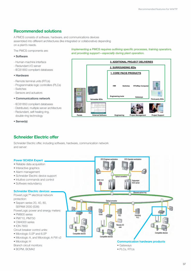
Recommended solutionsA PMCS consists of software, hardware, and communications devices assembled into different architectures (like integrated or collaborative) depending on a plant’s needs.
The PMCS components are:
• Software
- Human-machine interface- Redundant I/O server- IEC61850 compliant databases
• Hardware
- Remote terminal units (RTUs)- Programmable logic controllers (PLCs)- Switches- Sensors and actuators
• Communications network
- IEC61850 compliant databases- Distributed, multiple server architecture- Redundant, self-healing ring,
double-ring technology
• Server(s)
Schneider Electric offerSchneider Electric offer, including software, hardware, communication network and server:
Implementing a PMCS requires outlining specific processes, training operators, and providing support—especially during plant operation.
Communication hardware products• Gateways• PLCs, RTUs
Power SCADA Expert• Reliable data acquisition• Interactive graphics• Alarm management• Schneider Electric device support• Intuitive commands and control• Software redundancy
Schneider Electric devicesPowerLogic™ electrical network protection:• Sepam series 20, 40, 80,
SEPAM 2000 (S36)PowerLogic power and energy meters:• PM800 series• PM710, PM750• CM4000 series• ION 7650Circuit breaker control units:• Micrologic 5.0P and 6.0P• Micrologic A, and Micrologic A FW v2• Micrologic HBranch circuit monitors:• BCPM, BCM42
Recommended features for WWTP

2238
The main features of the Schneider Electric PMCS are:
Data acquisition and integration
PMCSs integrate power supply devices with PLCs, RTUs, controllers, and other intelligent energy devices. They can provide native, out-of-the-box support for all SEPAM Series 20, 40, 80, and SEPAM 2000 (S36), Micrologic 5.0P and 6.0P, Micrologic A,E, Micrologic A FW v2, Micrologic H, PowerLogic CM4000 series, PM800 series, PM710, PM750, ION7650, and BCPM/BCM42 devices. They enable access to meter data, can be used to control protection relays and digital outputs, and allow for remote configuration. They also interface with PLCs, RTUs, and electrical network equipment, as well as with other energy management or automation systems through Modbus TCP/IP. Devices can be added easily and configured rapidly with the easy-to-use Profile Wizard and Profile Editor. A scalable platform allows for remote devices and for user clients to be added as needed.
Alarms and events with 1ms timestamp support
Power SCADA Expert software sends operators alerts for outages or impending problems that could lead to equipment stress, failures, or downtime. Alarms can be configured to trigger on certain events, power thresholds, or equipment conditions. The software includes an event log for all PC-based and field events and alarms, including related conditions at the time of the event or alarm—all with accurate 1ms time stamping. It can easily discriminate between alarm levels (from less-critical to highly-critical) with a high-speed alarm response.
Operators can sort, filter, and print data by any alarm property, and configure specific alarms to change symbol color or flash an icon on a page. Operators can also view the five most recent alarms from every page, providing detailed information in an easy-to-understand format.
Power equipment control
With a PMCS, operators can perform fast, manual control operations by clicking on trigger buttons, and operate remote breakers, protection relays, and other power distribution equipment.
Real-time monitoring
PMCSs let operators monitor all power distribution points in an electrical network. They can view real-time power and energy consumption data, past trends and data logs, alarm conditions, equipment status (on/off, temperature, pressure, etc.), control triggers, and analysis tools. Single line diagrams allow for real-time monitoring and control of electrical network devices and power distribution points. Point-and-click navigation reveals deeper layers of detail. The software’s IEC- and ANSI-standard symbols and templates are fully animated and interactive, combining control and display functionality. Operators can easily configure the software’s dynamic coloring with default and user-defined colors and voltage levels.
Recommended features for WWTP

39
Analysis
Operators can plot trends on any variable a PMCS tracks, letting them instantly identify patterns that may lead to disturbances. A PMCS displays millisecond-accurate alarm data to help operators determine a particular sequence of events or perform a root cause analysis. By combining trends and alarm data, operators can carry out sophisticated disturbance analyses. The user-defined color coding and overlays show data series, time ranges, thresholds, and limits clearly. Operators can also view waveforms using ActiveX (waveforms from the ION8650 are captured via IEC61850 only), and they can record, save, and export trend data to archives.
Recommended features for WWTP

2240
Energy efficiency technology Below is an overview of technology commonly used to lower a WWTP energy consumption—without any significant change in its processes.
Low-loss transformers and motorsA new generation of transformers and motors made with high performance iron sheets and increased cross section copper windings can improve overall efficiency by up to 5%.
High-efficiency UV lampsUltraviolet (UV) radiation is a commonly used for disinfection in wastewater treatment plants since it can effectively neutralize most viruses and germs. UV disinfection also eliminates the need to generate, handle, transport, and store toxic, hazardous, or corrosive chemicals. UV radiation is produced by striking lamps containing mercury vapor with an electric arc to generate a charge. Low-pressure, high-intensity lamps are the more energy efficient technology.
Variable speed drivesWithout a variable speed drive (VSD) pump, the pump’s driving motor is typically run at a fixed speed and liquid flow is controlled with a valve or throttle. This means that the power requirement is virtually the same regardless of the liquid flow rate. However, if the valve or throttle is left fully open and the driving motor is adjusted to control the liquid flow rate, the power requirement can be slashed by 50% at an 80% nominal flow rate, for example. Therefore, substantial energy savings are possible wherever a plant uses a variable flow rate. Schneider Electric has developed a line of variable speed drives for pumping and other applications: Altivar 21 and Altivar 61.
MV motor supplyUsing a medium-voltage power supply for high-power (> 100kW) motors reduces the line currents, thereby diminishing the Joule losses in transformers, cables, and motors. A low-voltage power supply may be cost-prohibitive for large equipment or when several sets of cables are needed. Two configurations are possible for medium-voltage variable speed drives:
• A variable speed drive operating directly at a medium-voltage; or
• The use of step-down/step-up transformers, so that the power circuits are operating at a low voltage (400V or 690V).
The latter configuration has several advantages: it is easy to install, easy to retrofit, does not require a new motor, allows for easier maintenance, spare parts are more readily available, and it employs proven, widely-used technology. The same inverter can be used if a plant later decides to switch to a low-voltage motor. Schneider Electric has developed a line of medium-voltage motor controllers: Motorpact starters and Altivar variable speed drives.
Recommended features for WWTP

41
Energy management information system (EMIS)IntroductionAn EMIS tracks an organization’s energy performance, giving managers the information they need to boost energy efficiency and reduce energy costs.
An EMIS is typically composed of:• Metering architecture, including a communications network and power meters
and sensors• Software to collect, store, and report energy data, process data, and key
performance indicators.
ChallengeEnergy is typically the biggest operating expense for a WWTP. Moreover, plants’ energy needs are increasing rapidly due to population growth, stricter discharge regulations, and aging infrastructure. Most WWTP can cut their energy costs by 30% or more with the effective use of energy management information systems, energy efficiency measures, and process optimization.
Recommended solutionsAn EMIS should:• Collect data on energy consumption, process inputs and outputs (like m3
of water treated or kg of dry sludge), and other factors that affect energy consumption (like biological or chemical oxygen demand).
• Consolidate data and track key performance indicators such as kWh/m3 (power needed to treat one m3 of wastewater), kWh/kg BOD (energy required to eliminate 1 kg of Biochemical Oxygen Demand), and t CO2-eq (equivalent tons CO2 emissions).
• Generate energy performance tables, charts, and reports.
An EMIS can be implemented:• At a plant level, to improve the plant’s operational efficiency by eliminating
energy waste, and cut the plant’s production costs• At a corporate or municipal level, to allocate costs more effectively, boost
energy efficiency, and comply with environmental regulations.
An EMIS should bring the following benefits for a WWTP:• Cut energy consumption without affecting water quality• Benchmark best practices across plants• Negotiate more favorable power supply contracts, avoid billing errors, and
sub-bill more accurately• Optimize energy sources• Improve energy quality• Enhance CO2 emissions control for a smaller carbon footprint• Comply with environmental regulations.
ISO 50001:
An energy management program is typically based on the Plan-Do-Check-Act process recommended by ISO 50001. This process helps plants establish and prioritize energy conservation targets (Plan), implement specific practices to meet these targets (Do), monitor and measure energy performance improvements and cost savings (Check), and periodically review progress and make adjustments to their energy programs (Act). The use of an EMIS is strongly recommended at the Check phase.
Recommended features for WWTP

2242
Schneider Electric offersSchneider Electric has developed end-to-end energy management solutions that can be implemented at both a plant and corporate or municipal level.
Our systems help corporations and cities lower their energy bills, shrink their carbon footprint, and underscore their green image by:• Providing essential data for reducing energy consumption and measuring the
effects of energy efficiency efforts• Consolidating data at a corporate or municipal level for generating reports and
benchmarking.
For individual WWTPs, our systems can cut the plant’s energy consumption and, subsequently, operating costs by:• Tracking the energy performance of various processes• Reducing plant downtime and energy waste• Enhancing the energy efficiency of plant equipment.
Our systems also provide a high-level, consolidated view of the cost and benefits of energy management and sustainability plans. They let sustainability managers track energy savings and cost control indicators like ROI and GHG emissions—to make sure their organization is on track to meeting its targets.
Our systems include tested, validated, and documented metering architecture that is both modular and scalable, so as to meet a plant’s changing needs and capacity for investment.
Recommended features for WWTP
Day 04/30/2011
Electrical autonomy Energy usage analysis CO2 emissionsSummary
0100200300400500600700
00:00 01:00 02:00 03:00 04:00 05:00 06:00 07:00 08:00 09:00 10:00 11:00 12:00
Blower #1 Blower #2
Logout I Help
Plant energy performance
John SmithSouth Wastewater Treatment Plant Energy Efficiency
Electricity ratio
15%
5%
62%
15%
3%
Pretreatment
Primary treatment
Secondary treatment
Sludge treatment
Non production
Raw wastewater lifting
00:00 01:00 02:00 03:00 04:00 05:00 06:00 07:00 08:00 09:00 10:00 11:00 12:000
10
20
30
40
50
60
70
Wh/m3
Day 04/30/2011March 2011Month
Aeration blowers
kWh
0
25
50
75
100
125
150
175
200
225
Mon Tues Wed Thurs Fri Sat Sun
kWh/t dry sludge
Sludge dewatering
Week #17, 04/30/2011
Planet energy performance Electrical autonomy Energy usage analysisSummary Plant energy performance Electrical autonomy Energy usage analysis CO2 emissionsSummary
Total electrical consumption
Biogas Purchased
0
500
1 000
1 500
2 000
2 500
Jan Feb Mar Apr May Jun Jul Aug Sep Oct Nov Dec
MWh
Purchased electricity cost
euros
010 00020 00030 00040 00050 00060 00070 00080 00090 000
Jan Feb Mar Apr May Jun Jul Aug Sep Oct Nov Dec
YearYear
Electrical autonomy from biogas
March 2011
27%0 Max
2011 2011
Logout I HelpJohn SmithSouth Wastewater Treatment Plant Energy Efficiency

43
Productivity software, tools and services

2244
To support the water process throughout its life cycle, from the electrical network design, during operation and to modernization, we offer various services available in all countries.
Our network of qualified partners and our projects and service centres are able to provide electrical network services.
Design phase servicesTo ensure efficient solutions for WWTP project and high performance operation, we offer software, tools and services to support for structured preliminary and final design, and for specification for tender:• Consultancy and expert services• Energy efficiency solutions• Critical power solutions
Operating phase servicesTo avoid unexpected downtime of WWTP application, ensure a constant performance level and to reduce operating costs:• Maintenance and spare parts management• Site audits and repairs• Training
We conduct power quality and harmonic studies to identify previously undiagnosed problems that can reduce equipment life and interfere with reliable operation. As the upgrades come online, our installation services verify that the new equipment is damage-free, properly installed, and ready to meet optimum performance standards.
Modernization phase servicesTo reduce risks after a long period of WWTP operation and improve the performance of applications:• Diagnostics and feasibility studies• Retrofit expertise and consultancy• Project support
A systematic approach to upgrades and retrofits is the key to extending equipment life at a fraction of the replacement cost. We upgrade or replace circuit breakers with new technology; develop switchgear retrofit solutions; recondition LV and MV power circuit breakers; replace or repair drives.
Productivity software, tools and services

45
Commercial reference samples for designed and implemented electrical networks in WWTP (IEC & Nema)

2246
Wastewater treatment plant, Csepel (Hungary)Customer profileGenesis of the project
Some years ago in Budapest, Hungary, 600 000 m3/day of wastewater were discharged into the Danube. 46 % of this water were not treated at all.
In 2002, the Hungarian Program for Treatment of Waste Water specified that the City of Budapest City must to comply in 2010 with the objectives of the 1994 Sophia Convention, which aimed at the protection of the Danube. In addition, the treated water must also meet EU standards.
Customer objectivesThe City’s two objectives involve the construction of a plant capable of treating effluents generated by a population of 1,5 millions inhabitants.
Veolia and Suez are leading the consortium designing this wastewater treatment plant with a capacity of 350000 m3/ day, the largest in the European Union. To achieve this, the consortium needs a unique partner, Schneider Electric, taking the full responsibility of process automation and delivery of energy management solution.
Customer benefits• By reaching 95% of wastewater treated instead of 54%, Budapest City will
comply with European Union regulation
• The new wastewater treatment plant will allow energy efficiency
• Schneider Electric allowed for a 15% design cost reduction in design cost
Solution overviewA turnkey solution• Complete study and design of the architecture.
- Project management
- Standardization and objects library creation
- Full delivery and commissioning of motor control, process automation and energy efficient electrical network, from medium voltage to low voltage.
The upstream collaboration with Schneider Electric at the design stage allows standardisation and minimizes the risks all along the project.
Schneider Electric’s added value• Schneider Electric is a global company well implanted in Hungary. Furthermore,
Schneider Electric is a key and regular partner for Veolia and Suez.
• Schneider Electric, ensured a single point of contact for the customer, fully managed the key steps of the project, providing a turnkey electrical network and automation
• Deep technical involvement – not only limited to products but mainly focused on applications and projects.
Key figures
≥ 15% design cost reduction≥ 95% of wastewater treated
Commercial reference samples for designed and implemented electrical networks in WWTP (IEC & Nema)
2246

47
Commercial reference samples for designed and implemented electrical networks in WWTP (IEC & Nema)
47
Wastewater treatment plant, DijonCustomer profile• Degremont: Design&Build and commissioning of the plant
• Lyonnaise des Eaux: Plant operation
Both companies are subsidiaries of Suez Environment
• Plant size: 400 000 equivalent inhabitants (70 000 m3/day)
Customer objectives• No process interruption: this could result in the release of wastewater into the
environment
• Energy efficiency: conservation of energy ressources
• Environmentally friendly: high quality water released into the environment and no odour nuisance for the neighbourhood (compliance with EU regulations)
Customer benefits• High level technical support by having a single manufacturer’s equipment for
the automation and electrical network systems
• Flexible and extendable solution
Solution overviewA full Power & Control solution• MV supply with open ring
• Each process step managed as a functional unit connected with Ethernet bus
Schneider Electric’s added value• Customer intimacy
• Complete Power and Control solution
• Energy Efficiency expertise
Key figures
15% energy savings 95% availability

22482248
Wastewater treatment plant, Atotonilco (Mexico)Customer profileGenesis of the project
The Hidalgo state is one of the principal sources of agriculture in Mexico. Previous irrigation of fields using untreated wastewater has been a cause of major health and environmental concerns. As a part of the Sustainable Water Programme for the Mexico Valley, a water treatment plant in Atotonilco, 60 km from Mexico city, will be built.
Customer objectivesThe National Water Commision of Mexico, Conagua, intends to significantly improve environmental conditions and raise the overall water treatment rate in the country. Additionally, the project will provide treated water for irrigation of around 80,000 ha in the Tula Valley of Hidalgo, concurrently improving living conditions of approximately 300,000 inhabitants in the region without access to treated water.
Customer benefits• Atotonilco project will significantly improve environmental conditions and raise
overall water treatment rate of the country from 36% to 60%.
• Improved living conditions for the inhabitants and the quality of surface water bodies and streams that receive the wastewater.
Solution overviewA turnkey solutionThrough a consortium led by Impulsora del Desarrollo y el Empeleo en America Latina (IDEAL), and other stakeholders including ICA, DYCUSA, Green Gass, Atlatec, the Build-Operate-Transfer (BOT) will take place in two phases over three years.
• Phase 1: Reach a capacity of wastewater treatment of 23 m³/sec
• Phase 2: Increase the wastewater treatment capacity 12 m³/sec
Schneider Electric’s added value• Schneider Electric’s global presence making it a reliable partner with proven
practices around the world.
• Schneider Electric has a deep technical knowledge of electrical distribution not limited to products but also focused on applications and project management.
Commercial reference samples for designed and implemented electrical networks in WWTP (IEC & Nema)

4949
Notes

22502250
Notes

5151
Notes

05/2012
Make the most of your energySM
> For more information, go to the Schneider Electric website/Solutions > Waterwww.schneider-electric.com
Schneider Electric Industries SAS
Head Office35 rue Joseph Monier 92506 Rueil-Malmaison Cedex- FranceTel.: +33 (0)1 41 20 70 00www.schneider-electric.com
©2012 Schneider Electric. All Rights Reserved. Schneider Electric, Make the Most of your energy, Altistart, Altivar, Canalis, Compact, Masterpact, Micrologic, Motorpact, MotorSys, PowerLogic, Prisma, Propivar, TeSys, VarSet are trademarks owned by Schneider Electric Industries SAS or its affiliated companies. All other trademarks are property of their respective owners. SLTED112010EN
09/2012