electronic document and plan … iv: electronic document and plan submission requirements to the...
TRANSCRIPT

Appendix IV: Electronic Document and Plan Submission Requirements to the Design Guidelines and Performance Standards
Page 1 of 16
ELECTRONIC DOCUMENT AND PLAN SUBMISSION REQUIREMENTS
Planning, Architectural and Engineering Services Revision Date: May 2015
Appendix IV: Electronic Document and Plan Submission Requirements to the Design Guidelines and Performance Standards
Page 2 of 16
INTRODUCTION
The purpose of this document is to serve as a tight specification for producing and delivering CAD drawings and image files that document as-built conditions for all University construction projects. This guideline is intended to ensure consistency of materials and to maximize both short and long term usability of the construction documentation. Design Document Standards and Plan Submission Requirements document is intended to ensure that work produced for and submitted to the University is consistent in its ability to easily integrate into our existing file structure and database that is maintained by the University’s Planning, Architectural, and Engineering Services department. Adherence to these and other University standards is required. The Designer is responsible to ensure that they and their sub-consultants submit documents in accordance with these standards and requirements.
1 AUTOCAD To ensure consistency in the updating, use, and archiving of AutoCAD® files for our campuses; a standardized system has been implemented to ensure that drawings will be identified with relevant file numbers during the initial phases of each project. The University works off of the AutoCAD® 2012-13 format, therefore any submissions shall be in AutoCAD® 2012-13 format. The University has established a template of dwg. files to be used by all Designers and it is posted on the University’s PAES website under Contractors and Consultants. The template of dwg. files are already preset with the Line types and weights, standard symbols and arrows, text appearance and sizes, and standardized units and measurement scales, which follow the AIA guidelines for AutoCAD® files. All other nuances that the University requires are provided below.
File Format The University has an established Title Block and Cover Sheet template which includes all the layering requirements. No other file format shall be used. All information identified to be provided within the title block shall be filled in completely and in the proper location.
Electronic File Format As-built construction project drawings must be submitted to the University in full compliance with the most recent or prior version of AutoCAD® software at the time of submission (file extension = .DWG).
Scale, Unit and Tolerances All CAD drawing models should be drafted at full scale in architectural units, such that one drawing unit equals one inch.
Fonts and Text Styles Text styles and fonts may vary, but the use of font ROMANS.shx for most applications is desirable. Special fonts which are not packaged with AutoCAD® are not allowed. Dimensions, labels and notes, should be not less than 1/8” height on printed drawings
Appendix IV: Electronic Document and Plan Submission Requirements to the Design Guidelines and Performance Standards
Page 3 of 16
Blocks All entities within a block must be created on layer 0. Drawing entities translated into blocks from non-AutoCAD® systems must revert to layer 0 when exploded. And file translation from other systems which result in wall blocks within the .DWG file are unacceptable.
Image Files All images (JPGs, BMPs, and PNGs) included in a CAD drawing must be cut and pasted into the drawing so that they are embedded within the CAD file. Referenced images will be discarded and therefore might cause incomplete drawings. XRef’s must be inserted into sheet files as an attachment using the Relative Path as the Path Type. By setting the XRef’s to Relative Path, drawings can be moved as needed and still maintain their links, eliminating any further maintenance to re-link the XRef’s. The Absolute Path method of attaching XRef’s will not be permitted. XRef’s must be inserted using a 0,0,0 reference point. XRef’s can also be bound and packaged. Binding an XRef’s to a drawing makes the XRef’s a permanent part of the design drawing. Keeping all files together as a package allows functionality in any situation. This method shall apply to all submissions that do not use relative paths. The University’s Standard Border shall be used. The text/attributes shall be inserted into each sheet as an independent element. The text block shall not be altered (exploded, rearranged, etc.) in any way.
Model Space and Paper Space Model Space - Floor plans, elevations, sections, relevant dimensions and other drawings shall be in model space only. Paper Space - Each CAD file shall be set up to contain only one title block in paper space which references the building model(‘s) contained in model space. Tabs may not be created to accommodate multiple sheets. Any update revisions to the design that are reflected on the .dwgs submitted to the University for review must reflect the date revision and the revision bubbled on the drawing to clearly reflect what has been changed from the previous submission review.
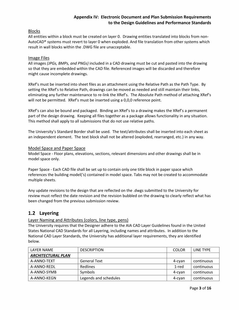
Layering Layer Naming and Attributes (colors, line type, pens) The University requires that the Designer adhere to the AIA CAD Layer Guidelines found in the United States National CAD Standards for all Layering, including names and attributes. In addition to the National CAD Layer Standards, the University has additional layer requirements, they are identified below.
LAYER NAME DESCRIPTION COLOR LINE TYPE
ARCHITECTURAL PLAN
A-ANNO-TEXT General Text 4-cyan continuous
A-ANNO-REDL Redlines 1-red continuous
A-ANNO-SYMB Symbols 4-cyan continuous
A-ANNO-KEGN Legends and schedules 4-cyan continuous

Appendix IV: Electronic Document and Plan Submission Requirements to the Design Guidelines and Performance Standards
Page 4 of 16
Space Allocation Plan
SP-AREA Area polylines for all interior spaces 252 continuous
SP-CASE Fixed Casework 11 continuous
SP-CASEHIDE Fixed Casework - Overhead 11 hidden4
SP-COLUMN Columns 40 continuous
SP-COL GRID Column grids, bubbles and nomenclature 8 cent
SP-DOOR Doors (including frames) blue continuous
SP-ELEVATOR Elevator cab 112 continuous
SP-EQUIP Fixed Equipment (AHU's, transformers, etc.) 13 continuous
SP-FIXT Plumbing Fixtures 35 continuous
SP-FLOOR Change in floor elevation (ramps, pits, etc.) 27 continuous
SP-FURN Movable furniture (panels, desks, etc.) yellow continuous
SP-GROSS Area polyline for entire building (gross SF) 30 continuous
SP-GUARDRAIL Handrails, guardrails, etc. 150 continuous
SP-HATCH Hatching/Poche varies continuous
SP-LOUVER Louvers white continuous
SP-NOPLOT No-plot layer magenta continuous
SP-OH Overhead info (beams, balconies, headers, etc.) white hidden4
SP-ROOF Roof edge, crickets, parapets, etc. 252 continuous
SP-SITE Site information (walks, curbs, drives, etc.) green continuous
SP-STAIR Stairs red continuous
SP-TEXT Text 72 continuous
SP-WALL Walls white continuous
SP-WALLHALF Walls - half or partial height 42 continuous
SP-WINDOW Windows (including frames) magenta continuous
All layers by line weight: default. All layers "true" status for plot mode except SP-NOPLOT
CAD File Translation Error-free CAD Drawing Deliverables:
Design firms may not have the same version of AutoCAD® currently used by the University. However, it is required that the Designer submit all DWG formatted CAD files upon project closeout. CAD files shall be fully compliant with the standards outlined herein, and shall have no significant loss of drawing entities or project data that can result from standard AutoCAD® file translation procedures.
A-ANNO-DIMS Dimensions 4-cyan continuous
A-ANNO-TTLB Border and Title Block 7-white continuous
A-ANNO-NOTE Job Notes 4-cyan continuous
A-ANNO-NPLT Construction lines, non-plotting information 7-white continuous
A-ANNO-KEYN Key notes 4-cyan continuous
Appendix IV: Electronic Document and Plan Submission Requirements to the Design Guidelines and Performance Standards
Page 5 of 16
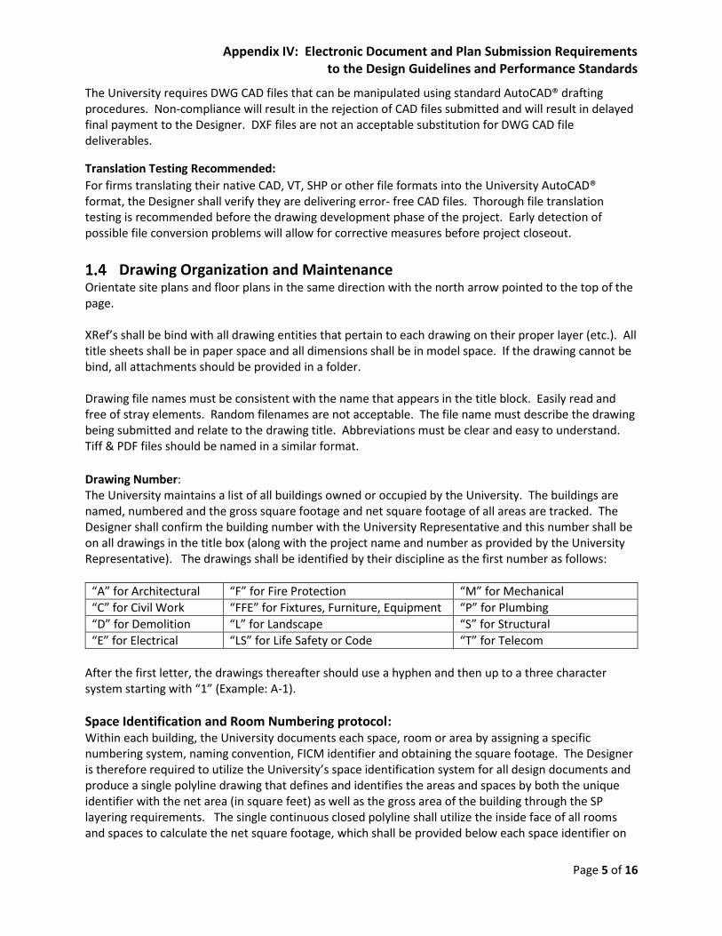
The University requires DWG CAD files that can be manipulated using standard AutoCAD® drafting procedures. Non-compliance will result in the rejection of CAD files submitted and will result in delayed final payment to the Designer. DXF files are not an acceptable substitution for DWG CAD file deliverables.
Translation Testing Recommended:
For firms translating their native CAD, VT, SHP or other file formats into the University AutoCAD® format, the Designer shall verify they are delivering error- free CAD files. Thorough file translation testing is recommended before the drawing development phase of the project. Early detection of possible file conversion problems will allow for corrective measures before project closeout.
Drawing Organization and Maintenance Orientate site plans and floor plans in the same direction with the north arrow pointed to the top of the page. XRef’s shall be bind with all drawing entities that pertain to each drawing on their proper layer (etc.). All title sheets shall be in paper space and all dimensions shall be in model space. If the drawing cannot be bind, all attachments should be provided in a folder. Drawing file names must be consistent with the name that appears in the title block. Easily read and free of stray elements. Random filenames are not acceptable. The file name must describe the drawing being submitted and relate to the drawing title. Abbreviations must be clear and easy to understand. Tiff & PDF files should be named in a similar format.
Drawing Number: The University maintains a list of all buildings owned or occupied by the University. The buildings are named, numbered and the gross square footage and net square footage of all areas are tracked. The Designer shall confirm the building number with the University Representative and this number shall be on all drawings in the title box (along with the project name and number as provided by the University Representative). The drawings shall be identified by their discipline as the first number as follows:
“A” for Architectural “F” for Fire Protection “M” for Mechanical
“C” for Civil Work “FFE” for Fixtures, Furniture, Equipment “P” for Plumbing
“D” for Demolition “L” for Landscape “S” for Structural
“E” for Electrical “LS” for Life Safety or Code “T” for Telecom
After the first letter, the drawings thereafter should use a hyphen and then up to a three character system starting with “1” (Example: A-1).
Space Identification and Room Numbering protocol: Within each building, the University documents each space, room or area by assigning a specific numbering system, naming convention, FICM identifier and obtaining the square footage. The Designer is therefore required to utilize the University’s space identification system for all design documents and produce a single polyline drawing that defines and identifies the areas and spaces by both the unique identifier with the net area (in square feet) as well as the gross area of the building through the SP layering requirements. The single continuous closed polyline shall utilize the inside face of all rooms and spaces to calculate the net square footage, which shall be provided below each space identifier on
Appendix IV: Electronic Document and Plan Submission Requirements to the Design Guidelines and Performance Standards
Page 6 of 16
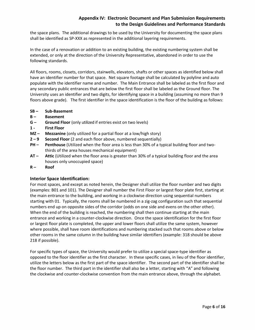
the space plans. The additional drawings to be used by the University for documenting the space plans shall be identified as SP-XXX as represented in the additional layering requirements. In the case of a renovation or addition to an existing building, the existing numbering system shall be extended, or only at the direction of the University Representative, abandoned in order to use the following standards. All floors, rooms, closets, corridors, stairwells, elevators, shafts or other spaces as identified below shall have an identifier number for that space. Net square footage shall be calculated by polyline and auto populate with the identifier name and number. The Main Entrance shall be labeled as the first floor and any secondary public entrances that are below the first floor shall be labeled as the Ground floor. The University uses an identifier and two digits, for identifying space in a building (assuming no more than 9 floors above grade). The first identifier in the space identification is the floor of the building as follows: SB – Sub-Basement B – Basement G – Ground Floor (only utilized if entries exist on two levels) 1 - First Floor MZ – Mezzanine (only utilized for a partial floor at a low/high story) 2 – 9 Second Floor (2 and each floor above, numbered sequentially) PH – Penthouse (Utilized when the floor area is less than 30% of a typical building floor and two-
thirds of the area houses mechanical equipment) AT – Attic (Utilized when the floor area is greater than 30% of a typical building floor and the area
houses only unoccupied space) R – Roof
Interior Space Identification: For most spaces, and except as noted herein, the Designer shall utilize the floor number and two digits (examples: B01 and 101). The Designer shall number the First Floor or largest floor plate first, starting at the main entrance to the building, and working in a clockwise direction using sequential numbers starting with 01. Typically, the rooms shall be numbered in a zig-zag configuration such that sequential numbers end up on opposite sides of the corridor (odds on one side and evens on the other other). When the end of the building is reached, the numbering shall then continue starting at the main entrance and working in a counter-clockwise direction. Once the space identification for the first floor or largest floor plate is completed, the upper and lower floors shall utilize the same system, however where possible, shall have room identifications and numbering stacked such that rooms above or below other rooms in the same column in the building have similar identifiers (example: 318 should be above 218 if possible). For specific types of space, the University would prefer to utilize a special space-type identifier as opposed to the floor identifier as the first character. In these specific cases, in lieu of the floor identifier, utilize the letters below as the first part of the space identifier. The second part of the identifier shall be the floor number. The third part in the identifier shall also be a letter, starting with “A” and following the clockwise and counter-clockwise convention from the main entrance above, through the alphabet.

Appendix IV: Electronic Document and Plan Submission Requirements to the Design Guidelines and Performance Standards
Page 7 of 16
The special space-type identifiers, and an example of the full identification for each, are as follows: L - Lobby L1A is the main lobby on the first floor LG- Lounge LG1C Third Lounge on the first floor V - Vestibule V1B is the second vestibule on the first floor C - Corridors C2B is the second corridor from the Lobby on the second floor S - Stair S3C is the third stairwell on the third floor E - Elevator E0A is the first elevator on the basement level RR - Restroom RR4C is the third restroom on the fourth floor CC - Concourse CC1A is the first concourse on the first floor
(A Concourse is a large open space for accommodating a gathering or passage of crowds)
Special Conditions: For these special conditions, the Designer should follow these rules:
In residential houses, in lieu of using “C” for corridors, the Designer should utilize “H” for hallway.
In residential houses, use “CL” for closets.
In office areas that are subdivided using cubicles, the Designer should label all cubicles “CU” and shall sequentially number same (example: CU-1, CU-2, etc.).
If the building has a space or floor that is not full height and is below grade, the Designer should not use B or SB, but should use the label “CS” as the identifier of crawl space
If a room is accessible through a door, hatchway or access panel, but its only purpose is to house ductwork or serve as a plenum, then the Designer should use the label “SH” as an identifier of a shaft
Multiple Rooms within a Space: Typically, each room will be identified with the next sequential number or value in a series. However, the exception is when a room is part of a larger space that serves one purpose. In these cases, rather than use the next sequential number or value, a letter shall be added to the overall space identifier, starting with “A” and continuing through the alphabet. An example is a residential apartment, where the living room may be identified as 201A, the bedroom as 201B and the bathroom as 201C, since they are all subcomponents of the same space. When the polyline drawing SP-XXX is done for these multiple room situations, the area and identification of the space shall be for the entire larger space, and shall not outline the rooms separately. Using the example above, the combined outline and net area of the entire apartment would be utilized (and not rooms 201A, 201B and 201C separately) and the entire space would then be labeled 201.
Outdoor Areas: Generally, outdoor spaces do not need to be labeled with a space identifier. The exception is if the outdoor space is to be utilized as programed space by the University. In those cases, the outdoor space shall be labeled with one of the following identifiers, and shall be included on drawing X-XXX: PL - Plaza A Plaza is an open outdoor area near or adjacent to a building, such as a public square or seating area. CY - Courtyard A Courtyard is an unroofed area that is completely or mostly enclosed by
the walls of a building. T - Terrace A Terrace is an open, with multiple relatively-level paved or planted platforms. B - Balcony A Balcony is an exterior space, normally on an upper floor of a building that
has only one point of entry and exit from the interior.

Appendix IV: Electronic Document and Plan Submission Requirements to the Design Guidelines and Performance Standards
Page 8 of 16
Door Identification: Doors should be numbered with the same system which reflects the room number to which the door
allows access. For example, the door to room 104 should be labeled “104A”, continuing sequentially
clockwise if there are multiple doors in the space and starting at the main entry to the space. Closet
doors should be included in the sequence and should not have a different system for labels.
Design Documents Submission Requirements by Phase: It is understood that no review and approval by the University of any design or design documents submitted by the Designer at any phase or stage will relieve the Designer of their responsibility to design the Project in accordance with the approved program and budget. Any design or design documents will be in full compliance with the University’s Design Standards and Performance Guidelines, Connecticut Building and Fire Safety Codes, all applicable laws, statutes, regulations and ordinances or of any responsibility of the Designer arising out of the University’s reliance on the Designer’s professional skill and ability to discharge the services required. When updating a drawing, the change block area of the .dwg (above the title block) must indicate the reason for the issue. i.e. “Issued for Bids,” – Issued for Construction” etc. Include number sequence and date of each issued revision. The Designer must note the revision date in the block area for all drawings revised from the previous review, prior to distribution for the next review. When submitting documents in CD – ROM, label the CD with the following information:
Project Name and Project Number
Building Number
The Designer’s Firm name and those of their sub-consultants
Identify what Submission Phase is on the CD and the Submission Date See PAES website under Contractors/Consultants for appropriate template.
Document Submissions for review based on Phasing Requirements The following documents are required to be submitted for review at identified review stage:
Plans required for review (when applicable to a Project)
PDS
SD
DD 50 & 100%
CD 50, 90 & 100%
Title Sheet X X X
Logistics Plan X X
Site Plan X X X
Utility Plan X X X
Landscape Plans X X X
Civil Plans X X X
Preliminary Framing Plans X
Structural Plans X X X
Architectural Floor Plans X X X
Interior Elevations X X
Exterior Elevations X X X

Appendix IV: Electronic Document and Plan Submission Requirements to the Design Guidelines and Performance Standards
Page 9 of 16
Building Sections X X X
Reflected Ceiling Plans X X
Enlarged Plans X X
Wall Sections X X
Details and Schedules X X
HVAC Load Calculations X X X
Mechanical Plans X X X
Mechanical Schedules X X
Mechanical Riser Diagrams X X
Mechanical Flow Diagrams X X
Mechanical Details and Schedules X X
Controls Points Schedule X X
Controls Location Plan X X
Electrical Riser Diagram X X X
Electrical Power Plan X X X
Electrical Lighting Plan X X
Electrical One-Line Diagrams X X X
Electrical Details and Schedules X X
Electrical Load Calculations X X X
Photometric Plan X X
Fire Protection Plans X X X
Fire Protection Riser Diagrams X X X
Fire Protection Details and Schedules X X
Plumbing Plans X X X
Plumbing Details and Schedules X X
Plumbing Riser Diagrams X X X
Special Systems Plans, Details and Schedules X X
Telecommunications Plans/Riser X X X
Furniture Layout Plans X X
Space Allocation Plans X
Other Documents required for review
Meeting Minutes X X X X
Outline Specifications (System Format) X
Outline Specifications (CSI Master Format 2004 or latest edition numbers and titles)
X X
Project Manual X X
Construction Cost Estimate* X X X
Value Engineering Analysis
Sustainable / LEED Design X X X
Code Review/Analysis X X X
Life Cycle Cost Analysis X X

Appendix IV: Electronic Document and Plan Submission Requirements to the Design Guidelines and Performance Standards
Page 10 of 16
Block Heating and Cooling Loads X X
Area Efficiency Calculations X X X
List of Proprietary, Non-University Standard Items, or when deviation from what is represented in the University Design Standards.
X X
Sequence of Operation X
Study Report and Basis of Program X
Perspective Sketches/Study Models (if required)
X X
Presentation Renderings (if required) X X
Presentation Models (if required) X X
Project Schedule with Construction Phasing X X X
Stormwater Management Plan (if required) X X
Soil Erosion and Sedimentation Control Plan (if required)
X X
Permit Applications (if applicable) X X
Vehicle and Pedestrian Traffic Control Plan (if required)
X
* LEED costs to be tracked separately
Progress and Phasing Submission Requirements: Below are the general submission requirements. Unless otherwise noted in your award assignment, the following requirements shall be followed and submitted to the University Representative:
Pre-Design (PDS): An electronic searchable PDF (ADOBE PRO), six (6) bound reports, photographs of the models and the models themselves, and a digital PDF (ADOBE PRO) version of the report for reproduction if necessary; where Conceptual Design is applicable, three (3) sets of professionally mounted presentation boards are required;
Schematic Design (“SD”) Review Phase: An electronic searchable PDF (ADOBE PRO) of the plans and specifications;
Design Development (“DD”) 50% Review Phase: An electronic searchable PDF (ADOBE PRO) of the plans and specifications and a detailed independent cost estimate. For large complex projects we will also require one (1) hard copy set of full-size drawings and specifications;
Design Development (“DD”) 100% Review Phase: An electronic searchable PDF (ADOBE PRO) of the plans and specifications, and an updated detailed independent cost estimate;
Construction Documents (“CD”) 50% Review Phase: An electronic searchable PDF (Adobe
Pro) of the plans and specifications, an updated detailed independent cost estimate, two (2)

Appendix IV: Electronic Document and Plan Submission Requirements to the Design Guidelines and Performance Standards
Page 11 of 16
hard copy half-size drawing sets, four (4) hard copy full-size drawing sets, and two (2) hard
copy of the specifications;
Construction Documents (“CD”) 90% Application Review Phase: An electronic searchable
PDF (ADOBE PRO) of the plans and specifications, updated detailed independent cost
estimate, two (2) set of half-size drawings, five (5) sets of full-size drawings, and three (3)
sets of specifications;
Construction Documents (“CD”) 100% Permit Review Phase: Two electronic file formats
(AutoCAD 2013 and PDF-Adobe Pro) of the plans and specifications electronically signed and
sealed by the Designer; an updated detailed independent cost estimate, two (2) set of half-
size drawings and four (4) sets of full-size drawings, and two (2) sets of specifications signed
and sealed by the Designer. Electronic signatures and stamp seals are acceptable. Permit
document sets that do not contain signatures and seals shall be returned without review;
Bidding/Proposal Phase: Should the 100% CD Permit Review Set get returned for
corrections, repeat the above submission requirement. An electronic searchable PDF
(ADOBE PRO) of the Addenda’s must be issued electronically and must be organized to
accommodate any necessary printing. Include appropriate stamps and signatures for any
calculations or sketches within the addenda package. Documents that do not reflect required
stamps and signatures shall be returned for resubmission;
In addition, at the conclusion of the bidding process, provide a Conformance Set reconciling
all bid clarifications to the Bid/Permit documents and incorporate any physical layout
changes that affect the Space Allocations Plans. An electronic PDF (ADOBE PRO) of the Space
Allocation Plans shall be submitted as Conformance to the University Representative;
Construction Administration: Upon request from the Contractor, the Designer shall release at no
additional cost to the Owner or Contractor, appropriate design documents for use by the
subcontractors and Contractor in formulating shop drawings. Such documents must be complete
and inclusive of any XRef’s, JPGs, BMPs, or PNGs imported into the documents. Condition of the
files being sent to the Contractor and/or subcontractor shall meet all University requirements;
Record Documents: an electronic searchable PDF (ADOBE PRO) of all drawings and specifications
and two (2) CD-ROMS in AutoCAD 2013, GIS/GPS and/or BIM Model. Submit Space Allocation
drawings separate from the contract document set.
The Record Set shall be made from the updated electronic files reflecting any changes during
construction, including the Contractors. The Designer is responsible for incorporating any field
changes that are identified by the Contractors red-lines or electronic file document into the
electronic Record Set prior to submitting them to the University Representative as final
documents. The Designer shall not charge the Contractor for incorporating the redline as-builts
Appendix IV: Electronic Document and Plan Submission Requirements to the Design Guidelines and Performance Standards
Page 12 of 16
into the electronic Record files. Should information be received from the redline documents be in
conflict with what was required by the Contractor’s contract and/or the Construction documents,
the Designer is responsible for bringing such conflict or discrepancy to the University
Representative’s attention.
Preparation and Submission of Space Allocation Plans: In addition to the drawings and specifications making up the Construction Documents, the University
requires a separate set of plan documents that document the appropriate labeling of space.
The University’s current facilities/space management software is FAMIS by Accruent. In order to
prepare for a building to be brought on-line under Operations, the Designer must prepare proper Space
Allocation Plans and provide an electronic set to the University Representative for review and
acceptance at no later than the end of the following phases: Design Development for review, 90%
Construction Documents for confirmation and acceptance, after bidding Conformance Set and a Record
Set reflecting any changes during construction (as-builts) - for all projects.
Similar to the Title Block and Cover Sheet template drawing standards, the Space Allocation CAD Floor
Plan Template has been established. The Designer must match the University’s standard 2-dimentional
drawing setup (per current version of AutoCAD – in .dwg format) as follows:
1. One file per floor of each building, oriented at lower left corner on coordinate 0,0 and lined up to
stack with all other floors.
2. Simple 2-D line work (no smartwalls, no duplication of line work, no 3-D blocks, etc.) following the
layer system noted below.
3. Z plane at height 0’-0” (flatten all work).
4. Polylines (on layer SP-AREA) placed along inside walls of every individual space except non-
occupiable HVAC shafts. Room number, type of space, square footage and FICM code shall be
represented.
5. Polyline (on layer SP-GROSS) placed along the outside wall of building.
See PAES website under Contractors & Consultants for Space Allocation CAD Floor Plan Template. See Appendix III Space Standards Guidelines for additional details on the FICM codes used.
Space/Area: Each base plan created of each floor must be in Model Space and have closed polylines drawn on a layer named SP-Area. This layer shall consist of a tracing of every room using a single continuous closed polyline to the inside face of all walls that define that room. All drawings must be purged completely to remove all unused blocks, Dimension styles, layers, line types, plot styles, text styles, multi-line styles, etc. No later than 100% Design Development Phase review documents, the University will require review of
the space or floor plan represented within the program reflecting all interior and exterior spaces for
verification that the University’s space identification guidelines have been followed and all labeling is
correct. Such plan shall reflect all floor numberings, corridor and other circulation space numberings,
Appendix IV: Electronic Document and Plan Submission Requirements to the Design Guidelines and Performance Standards
Page 13 of 16
elevator and stair numberings, room numberings, the room within a room numberings and door
numberings that have been programmed to date. Any corrections shall be incorporated and re-
submission shall be made at the 90% permit set for review and acceptance prior to releasing the bid set.
It is the intent that the space identifications that are shown on the design drawings shall serve as the
basis for the production of the signage for wayfinding, directories and room identification. Additionally,
the space identifications should be sufficient and comprehensive to be utilized for the programming of
the fire alarm system without modifications.
The Conformance Set of SP drawings shall be issued to the University Representative for Space
Planning’s upload to FAMIS. It is imperative that the Designer has complete continuous closed polylines
with each space being measured. The Designer shall be responsible for corrections and resubmission of
the documents should it be discovered that continuous closed polylines are not 100 percent complete.
The block that identifies the room name, room number, square footage and FICM number, shall be tied
to the polyline for each area or room.
When as-built documents are submitted, the Designer is responsible for updating the space plans to
reflect as-built conditions and incorporate a single continuous closed polyline to the inside space of all
rooms and spaces affected to incorporate its square footage calculations below the room or space
identifier. The Designer shall be responsible for corrections and resubmission of the documents should
it be discovered that continuous closed polylines are not 100 percent complete.
2 Electronic Programs The Designer shall be fully versed in all programs offered in Microsoft Office Suite. The Project Schedule
shall be in the latest version of Microsoft Project or an acceptable format as determined by the
University Representative to properly plan and track progress of the Project Schedule. The Project
Schedule will be provided in an electronic file format for review and acceptance within two
weeks of assignment/contract execution. The Project Schedule will include all milestones
identified as part of the Project and shall include but not limited to the following: (1) deadlines
for information exchange and decision-making for programing and design, (2) major meetings,
(3) progress and mid and end-of-phase document submissions, (4) Department review/approval
periods, (5) submission for approval of authorities having jurisdiction, (6) value engineering
sessions, (7) prequalification and bidding periods, (8) Construction Administration and 9)
Closeout periods and (10) other major activities as are appropriate to the Project. The Designer
is required to provide an update on the schedule and notify the Department of any delays or
impediments that may be causing the design schedule to slip and present any adjustments
required to recover the accepted schedule in increments required by the University Representative.
3 REVIT / BIM Standards The University recognizes the potential benefits of Building Information Modeling (BIM) software and
has developed elementary standards for A/E consultant firms that work in this media. The Designer is
required to use parametric BIM authoring software for the creation of models that include all geometry,
Appendix IV: Electronic Document and Plan Submission Requirements to the Design Guidelines and Performance Standards
Page 14 of 16
physical characteristics and product data needed to describe the design and construction project in
detail. Submitted files should be in AUTODESK REVIT format (.rvt) or must be Revit compatible. All Revit
submissions shall also be accompanied by a converted version of the drawing set in AutoCAD 2012-13
format.
The Designer is required to utilize Revit or other 3D modeling programs for its documentation. If the Design utilizes Revit or BIM modeling, then it shall provide the documents in their native format to both the Owner and Contractor (for coordination purposes) both prior to the start of construction and the end of construction. In addition, the Designer shall also provide the documents converted into two-dimension CAD drawings (in the latest version of CAD). Under both scenarios, the Designer shall have the obligation to coordinate the design such that all work that is shown fits within the spaces that are provided and that there are no major conflicts in the different aspects of the work.
4 SURVEY/GIS STANDARDS Surveying, Civil Engineering and Landscape Architecture must adhere to the following standards. Drawings created under the Surveying Standards must also adhere to the CAD and GIS Standards. Any University requirements that may conflict with State requirements shall be brought to the attention of the University Representative for clarification. When surveying any area within the University Campuses, the use of GPS logging shall be used. Any subsurface work shall require documentation by the surveyor and incorporated into the drawings. Document the depth of pipe, size, type, GPS coordinates of the pipe and its direction. The designated grid will be fully surveyed to locate all infrastructure surface fixtures not limited to man holes, access valve boxes, catch basins, fire hydrants etc. When required within the assignment, ground penetrating radar shall be used to locate underground infrastructure and document its coordinates utilizing GPS and accuracy and margin of error defined. All captured data will be submitted in the standard GIS format used by the University.
The mapping and survey shall be in accordance with the "Regulations of Connecticut State Agencies, Sections 20-300b-1 thru 20-300b-20", and the "Minimum Standards for Surveys and Maps in the State of Connecticut" endorsed by the Connecticut Association of Land Surveyors, Inc. on September 26, 1996.
The type of survey will be a "Topographic and General Location Survey". The topographic and existing location survey will be to "A-2" and "T -2" standards. Vertical accuracy will be to V-2 standards. Utilities will be to "T-2" and Class "D" (compiled) accuracy. Survey shall depict the following (where applicable for the project):
topographic and location survey of the project
1 ft. contours, spot grades and finish floor elevations of all buildings and all building entrance elevations;
All site features within the project area, including but not limited to utilities, light standards, signage, roads, drives, parking areas, curbing, sidewalks (bituminous, concrete, pavers or stone dust, etc.), paths, stairs, retaining walls, fencing, emergency call boxes, guiderail, benches, trash receptacles and mailboxes locations;
All Trees within the project area; identify location and tree tag number and for shrubs; show shrub mass boundaries;

Appendix IV: Electronic Document and Plan Submission Requirements to the Design Guidelines and Performance Standards
Page 15 of 16
All walkway elevations, at all intersections and change in direction and every 25’-0” on center;
All top and bottom of curb elevations, at all intersections and change in direction and every 25’-0” on center;
All top and bottom of wall elevations, at all intersections and change in direction and every 25’-0” on center;
All corners of patios.
Top of frame elevations on all utility structures;
Depict flow lines and inverts for storm water and sanitary sewer;
Location and compilation of underground (U/G) utilities wetlands or wetland flags, and property boundary from information supplied by Municipal, Facility, and utility companies willing to supply information;
Electronic base map, including point files shall be provided. Provide two (2) stamped and signed copies of completed survey.
Horizontal control will be recovered in the Connecticut State Plane Coordinate system. North American Datum of 1983 (NAD '83(2011)). Control will be established based on available Control Points recovered from State of Connecticut DOT or municipal sources. Otherwise, control will be established using Global Positioning Satellite (GPS) survey procedures. Accuracy and margin of error must be defined and documented in the metadata.
Vertical control will be established in North American Vertical Datum of 1988. (NAVD '88)
A minimum of two (2) horizontal and vertical control points with ties will be established in the project area for use during future construction projects.
Geographic Coordinate System =NAD_1983_StatePlane_Connecticut_FIPS_0600_Feet Projection: Lambert Conformal Conic
Drawing Format Requirements: The drawing will be prepared in AutoCAD 2010 Format and GIS Shape (.shp) Files, if available.
Sheet size and an agreed upon scale will be determined as subject to layout requirements for the project area. Border requirements and layer naming conventions will be to University of Connecticut standards.
All grid positioned work shall be in an AutoCAD model space environment drawn at a one (1) to one (1) scale. For production of hard copy mapping, sheet borders, notes, etc. shall be in an AutoCAD paper space environment utilizing viewports with respect to required scale.
Orient north arrow and magnetic north toward the top of the sheet.
All line work shall be two dimensional with a zero (0) elevation with the exception of contour lines which shall have their respective elevation assigned.
Include legend of symbols, linetypes and abbreviations
All AutoCAD entities such as boundaries, utilities, contouring, planimetric features, etc. shall be segregated on corresponding layers, linetypes and colors.

Appendix IV: Electronic Document and Plan Submission Requirements to the Design Guidelines and Performance Standards
Page 16 of 16
Raster Images: When requested, scale rectified digital color aerial orthophoto imagery, photo scale of 1"=350';
0.50 ft. pixel resolution.
Vector mapping scale is 1”=40’ photogrammetric mapping. Utilize projected coordinate system NAD_1983_StatePlane_Connecticut_FIPS_0600_Feet for digital orthophotos spatial reference.
Horizontal Control based on North American Datum of 1983 (NAD 83(2011)).
Vertical Control based on North American Vertical Datum of 1988 (NAVD 88). The drawing will be prepared in AutoCAD 2012-13 Format and converted to GIS Shape (.shp) Files. Sheet size and an agreed upon scale will be determined as subject to layout requirements for the project area. Border requirements will be to University of Connecticut standard template. For production of hard copy mapping, sheet borders, notes, etc. shall be in an AutoCAD paper space environment utilizing viewports with respect to required scale. Orient north arrow and magnetic north toward the top of the sheet. All line work shall be two dimensional with a zero (0) elevation with the exception of contour lines which shall have their respective elevation assigned. Include legend of symbols, linetypes and abbreviations all AutoCAD entities such as boundaries, utilities, contouring, planimetric features, etc. shall be segregated on corresponding layers, linetypes and colors.
Deliverables: Two (2) sets of signed and sealed paper mapping documents of the survey. One (1) CD-ROM disc containing all project electronic files. The electronic files shall be delivered in two formats: 1. AutoCAD 2010 and 2. PDF (Adobe Pro) files. If GIS is available, please provide either .shp files or geodatabase (GIS).
One (1) CD-ROM disc containing all project electronic files. The electronic files shall be delivered in three formats: 1. AutoCAD 2012-13, 2. Revit files (if native format of drawings is Revit), 3. PDF (Adobe Pro) files, or .shp files or geodatabase (GIS).