elevate your ride1 11-mc-ind1 rev 8 11/25/2019 kit mc-2920, mc-2929 indian touring series...
TRANSCRIPT
1 REV 8 11/25/201911-MC-IND1
KIT # MC-2920, MC-2929INDIAN TOURING SERIES
2014-PRESENT
Arnott® is committed to the quality of its products. If you have a question or problem with any Arnott product, please contact Arnott by calling 800-251-8993 during normal business hours or email [email protected].
(In the EU please call +31 (0)73 7850 580 or email [email protected]).
WARNING: DO NOT inflate the air suspension system until it is installed. Inflation of the air suspension system before both ends are supported by the motorcycle’s frame and/or appropriate suspension components may result in serious personal injury and/or damage to the air suspension system. The maximum recommended air spring inflation pressure is 200 psi.
Congratulations on your purchase of an Arnott® Motorcycle Air Suspension system. This system provides you with the ability to maintain your bike at a constant level regardless of load, resulting in enhanced vehicle ride, handling, and performance. We at Arnott Incorporated are proud to offer a high quality product at the
industry’s most competitive pricing. Thank you for your confidence in us and our product.
Proper installation is essential to experience and appreciate the benefits of this system. Please take a moment to review these installation instructions before you begin to install these components on your motorcycle. The removal and installation of air suspension products should only be performed by a fully qualified, ASE
Certified, professional.
It is equally important to be aware of all necessary safety measures while installing your new Air Suspension System. This includes proper lifting and immobilizing of the motorcycle and isolation of any stored energy to
prevent personal injury or property damage.
"Elevate Your Ride "®
2 REV 8 11/25/201911-MC-IND1
KIT # MC-2920, MC-2929INDIAN TOURING SERIES
2014-PRESENT
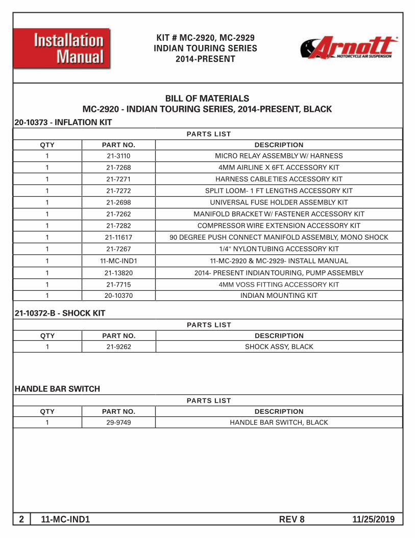
20-10373 - INFLATION KIT PARTS LIST
QTY PART NO. DESCRIPTION1 21-3110 MICRO RELAY ASSEMBLY W/ HARNESS
1 21-7268 4MM AIRLINE X 6FT. ACCESSORY KIT
1 21-7271 HARNESS CABLE TIES ACCESSORY KIT
1 21-7272 SPLIT LOOM- 1 FT LENGTHS ACCESSORY KIT
1 21-2698 UNIVERSAL FUSE HOLDER ASSEMBLY KIT
1 21-7262 MANIFOLD BRACKET W/ FASTENER ACCESSORY KIT
1 21-7282 COMPRESSOR WIRE EXTENSION ACCESSORY KIT
1 21-11617 90 DEGREE PUSH CONNECT MANIFOLD ASSEMBLY, MONO SHOCK
1 21-7267 1/4" NYLON TUBING ACCESSORY KIT
1 11-MC-IND1 11-MC-2920 & MC-2929- INSTALL MANUAL
1 21-13820 2014- PRESENT INDIAN TOURING, PUMP ASSEMBLY
1 21-7715 4MM VOSS FITTING ACCESSORY KIT1 20-10370 INDIAN MOUNTING KIT
21-10372-B - SHOCK KIT PARTS LIST
QTY PART NO. DESCRIPTION1 21-9262 SHOCK ASSY, BLACK
BILL OF MATERIALSMC-2920 - INDIAN TOURING SERIES, 2014-PRESENT, BLACK
HANDLE BAR SWITCH PARTS LIST
QTY PART NO. DESCRIPTION1 29-9749 HANDLE BAR SWITCH, BLACK
3 REV 8 11/25/201911-MC-IND1
KIT # MC-2920, MC-2929INDIAN TOURING SERIES
2014-PRESENT
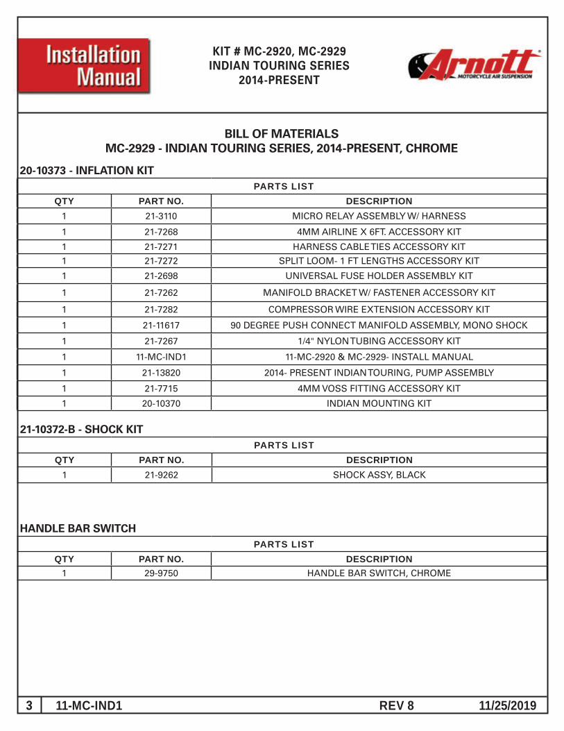
20-10373 - INFLATION KIT PARTS LIST
QTY PART NO. DESCRIPTION1 21-3110 MICRO RELAY ASSEMBLY W/ HARNESS
1 21-7268 4MM AIRLINE X 6FT. ACCESSORY KIT
1 21-7271 HARNESS CABLE TIES ACCESSORY KIT
1 21-7272 SPLIT LOOM- 1 FT LENGTHS ACCESSORY KIT
1 21-2698 UNIVERSAL FUSE HOLDER ASSEMBLY KIT
1 21-7262 MANIFOLD BRACKET W/ FASTENER ACCESSORY KIT
1 21-7282 COMPRESSOR WIRE EXTENSION ACCESSORY KIT
1 21-11617 90 DEGREE PUSH CONNECT MANIFOLD ASSEMBLY, MONO SHOCK
1 21-7267 1/4" NYLON TUBING ACCESSORY KIT
1 11-MC-IND1 11-MC-2920 & MC-2929- INSTALL MANUAL
1 21-13820 2014- PRESENT INDIAN TOURING, PUMP ASSEMBLY
1 21-7715 4MM VOSS FITTING ACCESSORY KIT
1 20-10370 INDIAN MOUNTING KIT
21-10372-B - SHOCK KIT PARTS LIST
QTY PART NO. DESCRIPTION1 21-9262 SHOCK ASSY, BLACK
BILL OF MATERIALSMC-2929 - INDIAN TOURING SERIES, 2014-PRESENT, CHROME
HANDLE BAR SWITCH PARTS LIST
QTY PART NO. DESCRIPTION1 29-9750 HANDLE BAR SWITCH, CHROME
4 REV 8 11/25/201911-MC-IND1
KIT # MC-2920, MC-2929INDIAN TOURING SERIES
2014-PRESENT
GENERAL INFORMATION:
Reading this manual signifies your agreement to the terms of the general release, waiver of liability, and hold harmless agreement, the full text of which is available at www.arnottcycles.com.
• Avoid damage to air lines and electrical components.• Removal and installation is only to be performed by fully qualified personnel.
CAUTION: Damage to the motorcycle and air suspension system can be incurred if work is carried out in a manner other than specified in the instructions or in a different sequence.
To avoid the possibility of short circuits while working with electric components consult your owner's manual on how to disconnect your battery.
Use a solid, level surface to position the bike on a motorcycle lift and use all recommended safety techniques. Lift the bike so the rear wheel is just slightly off the ground.
Refer to the Owner’s Manual for the bike and instructions for the motorcycle lift for all correct lifting procedures. It is also recommended that you protect any chrome or painted surfaces that may be damaged during lifting, removal or installation process.
Each owner or installer is unique, therefore installation of this system can be done many different ways. The mounting locations of the compressor and inflation switch are suggestions by our engineers. If proper wiring guidelines and instructions are followed,
relocation of the compressor or switch will neither affect the system operation nor void your warranty.
Adjust air shock pressure as required for desired ride quality to maximize the benefits of your system. Excess pressure will result in a firmer ride, too little pressure will allow the suspension to bottom out.
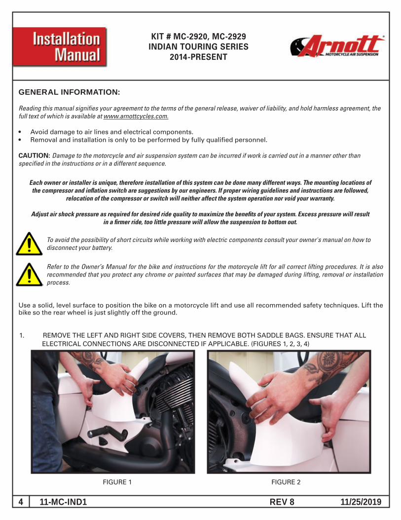
1. REMOVE THE LEFT AND RIGHT SIDE COVERS, THEN REMOVE BOTH SADDLE BAGS. ENSURE THAT ALL ELECTRICAL CONNECTIONS ARE DISCONNECTED IF APPLICABLE. (FIGURES 1, 2, 3, 4)
FIGURE 1 FIGURE 2
5 REV 8 11/25/201911-MC-IND1
KIT # MC-2920, MC-2929INDIAN TOURING SERIES
2014-PRESENT
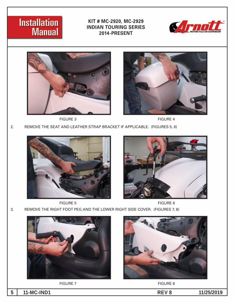
2. REMOVE THE SEAT AND LEATHER STRAP BRACKET IF APPLICABLE. (FIGURES 5, 6)
FIGURE 7 FIGURE 8
FIGURE 5
FIGURE 3 FIGURE 4
3. REMOVE THE RIGHT FOOT PEG AND THE LOWER RIGHT SIDE COVER. (FIGURES 7, 8)
FIGURE 6

6 REV 8 11/25/201911-MC-IND1
KIT # MC-2920, MC-2929INDIAN TOURING SERIES
2014-PRESENT
FIGURE 9 FIGURE 10
4. REMOVE ALL REAR FENDER TRIM ON BOTH SIDES, INCLUDING ANTENNA. (FIGURES 9, 10, 11, 12, 13, 14)
FIGURE 10
FIGURE 12FIGURE 11
FIGURE 14FIGURE 13
7 REV 8 11/25/201911-MC-IND1
KIT # MC-2920, MC-2929INDIAN TOURING SERIES
2014-PRESENT
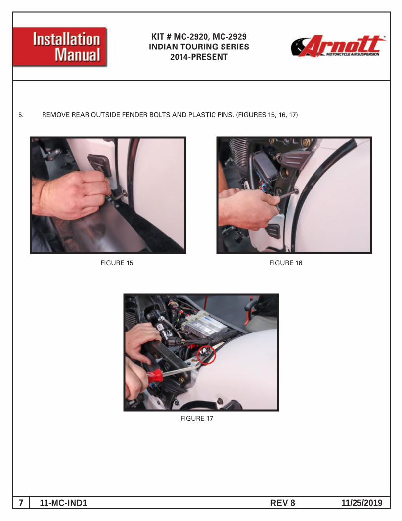
5. REMOVE REAR OUTSIDE FENDER BOLTS AND PLASTIC PINS. (FIGURES 15, 16, 17)
FIGURE 15 FIGURE 16
FIGURE 17
8 REV 8 11/25/201911-MC-IND1
KIT # MC-2920, MC-2929INDIAN TOURING SERIES
2014-PRESENT
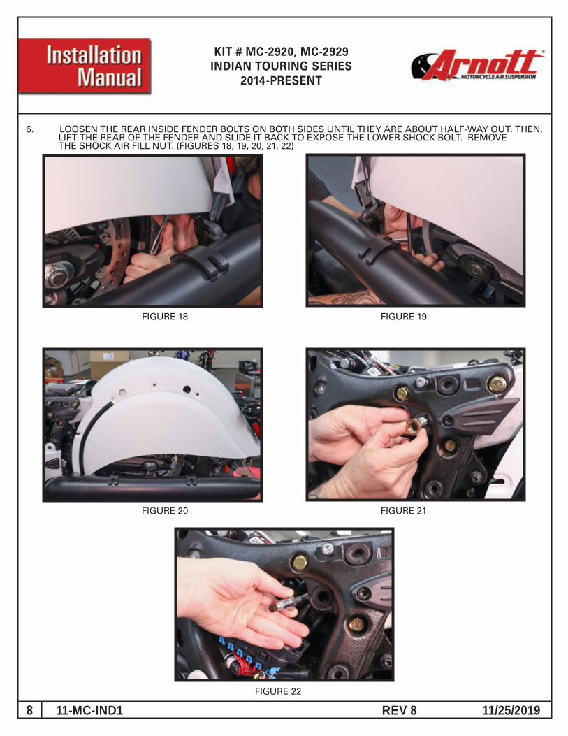
6. LOOSEN THE REAR INSIDE FENDER BOLTS ON BOTH SIDES UNTIL THEY ARE ABOUT HALF-WAY OUT. THEN, LIFT THE REAR OF THE FENDER AND SLIDE IT BACK TO EXPOSE THE LOWER SHOCK BOLT. REMOVE THE SHOCK AIR FILL NUT. (FIGURES 18, 19, 20, 21, 22)
FIGURE 18 FIGURE 19
FIGURE 20 FIGURE 21
FIGURE 22
9 REV 8 11/25/201911-MC-IND1
KIT # MC-2920, MC-2929INDIAN TOURING SERIES
2014-PRESENT
FIGURE 23 FIGURE 24
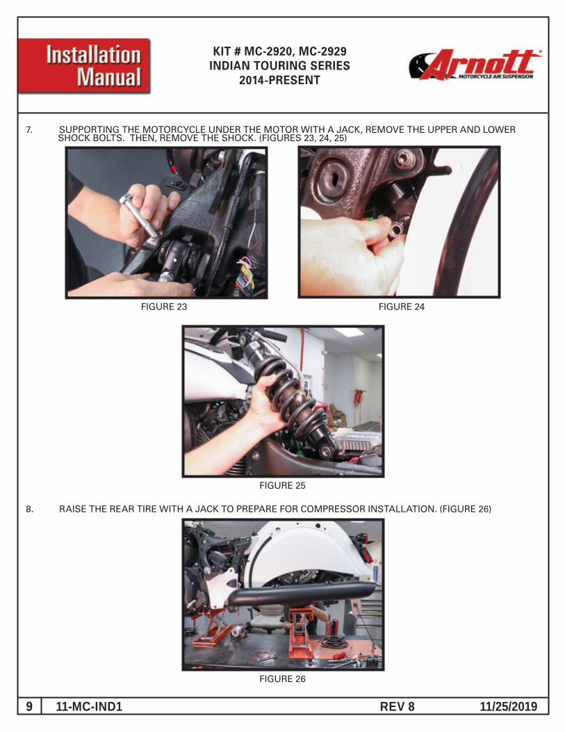
7. SUPPORTING THE MOTORCYCLE UNDER THE MOTOR WITH A JACK, REMOVE THE UPPER AND LOWER SHOCK BOLTS. THEN, REMOVE THE SHOCK. (FIGURES 23, 24, 25)
FIGURE 25
8. RAISE THE REAR TIRE WITH A JACK TO PREPARE FOR COMPRESSOR INSTALLATION. (FIGURE 26)
FIGURE 26
10 REV 8 11/25/201911-MC-IND1
KIT # MC-2920, MC-2929INDIAN TOURING SERIES
2014-PRESENT
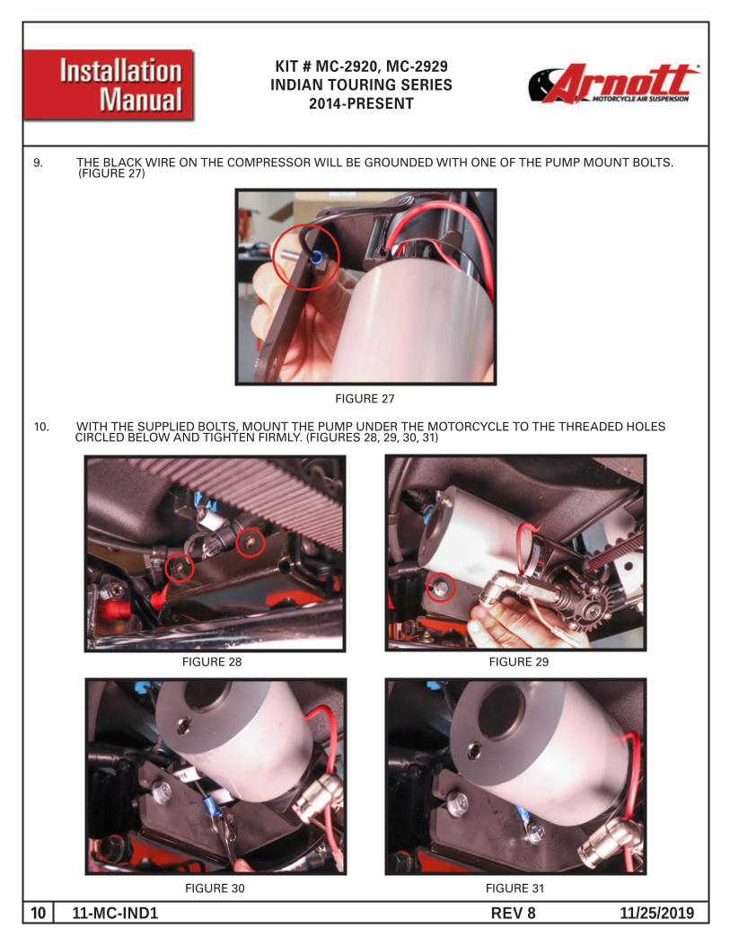
9. THE BLACK WIRE ON THE COMPRESSOR WILL BE GROUNDED WITH ONE OF THE PUMP MOUNT BOLTS. (FIGURE 27)
FIGURE 28 FIGURE 29
10. WITH THE SUPPLIED BOLTS, MOUNT THE PUMP UNDER THE MOTORCYCLE TO THE THREADED HOLES CIRCLED BELOW AND TIGHTEN FIRMLY. (FIGURES 28, 29, 30, 31)
FIGURE 27
FIGURE 30 FIGURE 31
11 REV 8 11/25/201911-MC-IND1
KIT # MC-2920, MC-2929INDIAN TOURING SERIES
2014-PRESENT
FIGURE 32 FIGURE 33
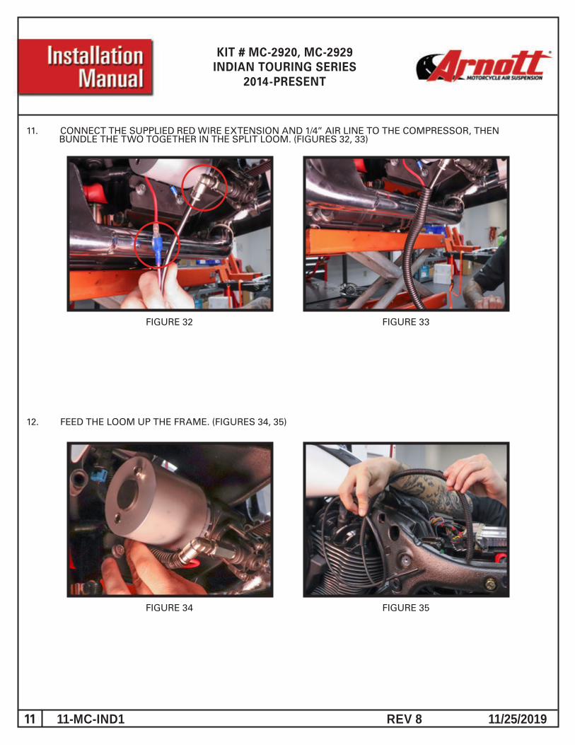
11. CONNECT THE SUPPLIED RED WIRE EXTENSION AND 1/4” AIR LINE TO THE COMPRESSOR, THEN BUNDLE THE TWO TOGETHER IN THE SPLIT LOOM. (FIGURES 32, 33)
FIGURE 34 FIGURE 35
12. FEED THE LOOM UP THE FRAME. (FIGURES 34, 35)
12 REV 8 11/25/201911-MC-IND1
KIT # MC-2920, MC-2929INDIAN TOURING SERIES
2014-PRESENT
FIGURE 36 FIGURE 37
FIGURE 38 FIGURE 39
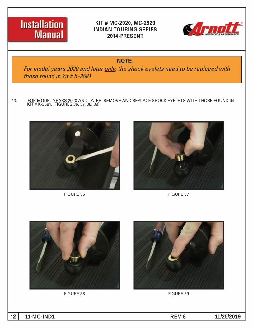
NOTE:
For model years 2020 and later only, the shock eyelets need to be replaced with those found in kit # K-3581.
13. FOR MODEL YEARS 2020 AND LATER, REMOVE AND REPLACE SHOCK EYELETS WITH THOSE FOUND IN KIT # K-3581. (FIGURES 36, 37, 38, 39)
13 REV 8 11/25/201911-MC-IND1
KIT # MC-2920, MC-2929INDIAN TOURING SERIES
2014-PRESENT
FIGURE 34 FIGURE 35
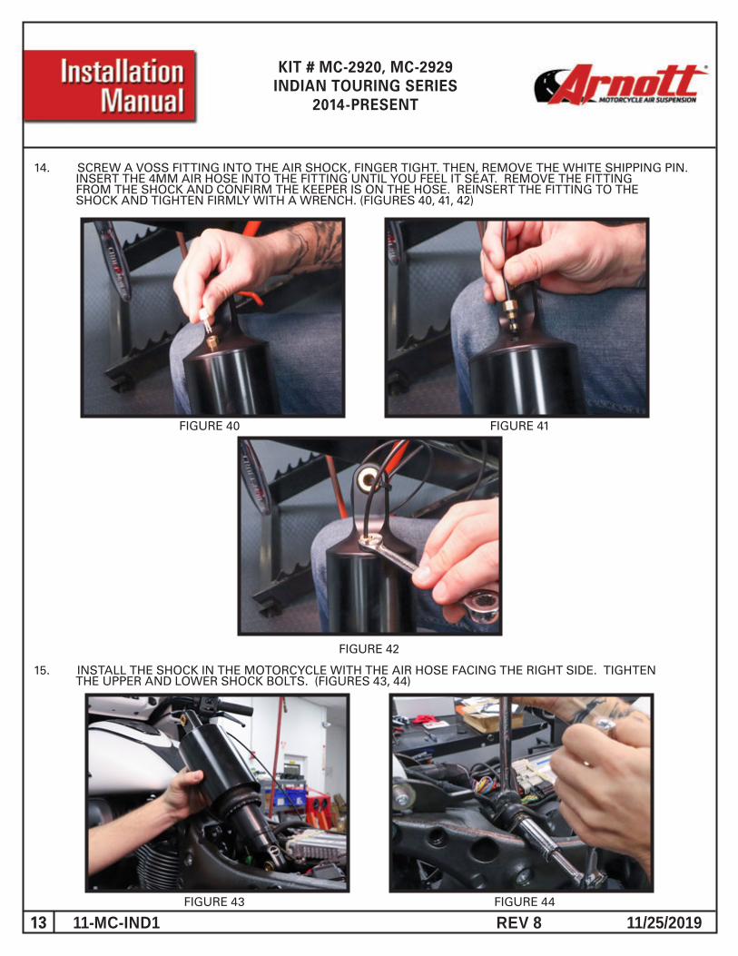
14. SCREW A VOSS FITTING INTO THE AIR SHOCK, FINGER TIGHT. THEN, REMOVE THE WHITE SHIPPING PIN. INSERT THE 4MM AIR HOSE INTO THE FITTING UNTIL YOU FEEL IT SEAT. REMOVE THE FITTING FROM THE SHOCK AND CONFIRM THE KEEPER IS ON THE HOSE. REINSERT THE FITTING TO THE SHOCK AND TIGHTEN FIRMLY WITH A WRENCH. (FIGURES 40, 41, 42)
FIGURE 40 FIGURE 41
FIGURE 42
FIGURE 43 FIGURE 44
15. INSTALL THE SHOCK IN THE MOTORCYCLE WITH THE AIR HOSE FACING THE RIGHT SIDE. TIGHTEN THE UPPER AND LOWER SHOCK BOLTS. (FIGURES 43, 44)
14 REV 8 11/25/201911-MC-IND1
KIT # MC-2920, MC-2929INDIAN TOURING SERIES
2014-PRESENT
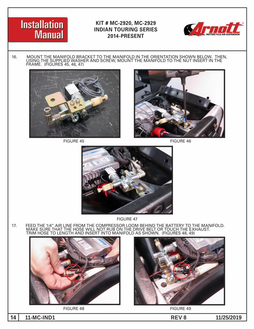
16. MOUNT THE MANIFOLD BRACKET TO THE MANIFOLD IN THE ORIENTATION SHOWN BELOW. THEN, USING THE SUPPLIED WASHER AND SCREW, MOUNT THE MANIFOLD TO THE NUT INSERT IN THE FRAME. (FIGURES 45, 46, 47)
FIGURE 47
FIGURE 45 FIGURE 46
FIGURE 48 FIGURE 49
17. FEED THE 1/4” AIR LINE FROM THE COMPRESSOR LOOM BEHIND THE BATTERY TO THE MANIFOLD. MAKE SURE THAT THE HOSE WILL NOT RUB ON THE DRIVE BELT OR TOUCH THE EXHAUST. TRIM HOSE TO LENGTH AND INSERT INTO MANIFOLD AS SHOWN. (FIGURES 48, 49)
15 REV 8 11/25/201911-MC-IND1
KIT # MC-2920, MC-2929INDIAN TOURING SERIES
2014-PRESENT
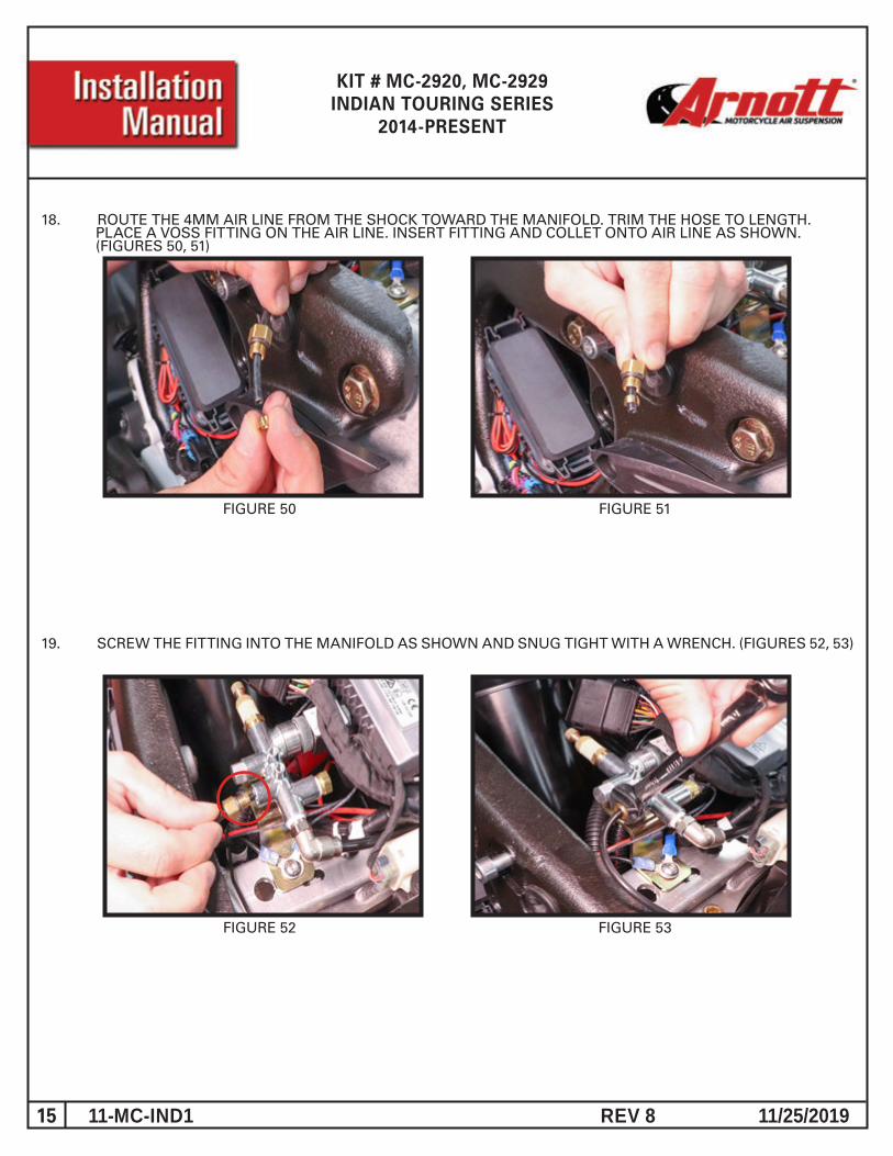
18. ROUTE THE 4MM AIR LINE FROM THE SHOCK TOWARD THE MANIFOLD. TRIM THE HOSE TO LENGTH. PLACE A VOSS FITTING ON THE AIR LINE. INSERT FITTING AND COLLET ONTO AIR LINE AS SHOWN. (FIGURES 50, 51)
FIGURE 50 FIGURE 51
19. SCREW THE FITTING INTO THE MANIFOLD AS SHOWN AND SNUG TIGHT WITH A WRENCH. (FIGURES 52, 53)
FIGURE 52 FIGURE 53
16 REV 8 11/25/201911-MC-IND1
KIT # MC-2920, MC-2929INDIAN TOURING SERIES
2014-PRESENT
FIGURE 54 FIGURE 55
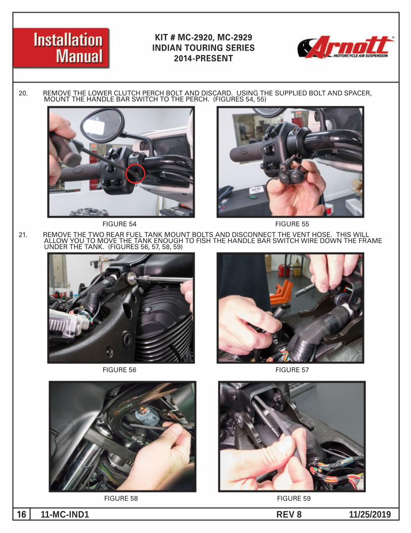
20. REMOVE THE LOWER CLUTCH PERCH BOLT AND DISCARD. USING THE SUPPLIED BOLT AND SPACER, MOUNT THE HANDLE BAR SWITCH TO THE PERCH. (FIGURES 54, 55)
FIGURE 56 FIGURE 57
21. REMOVE THE TWO REAR FUEL TANK MOUNT BOLTS AND DISCONNECT THE VENT HOSE. THIS WILL ALLOW YOU TO MOVE THE TANK ENOUGH TO FISH THE HANDLE BAR SWITCH WIRE DOWN THE FRAME UNDER THE TANK. (FIGURES 56, 57, 58, 59)
FIGURE 58 FIGURE 59
17 REV 8 11/25/201911-MC-IND1
KIT # MC-2920, MC-2929INDIAN TOURING SERIES
2014-PRESENT
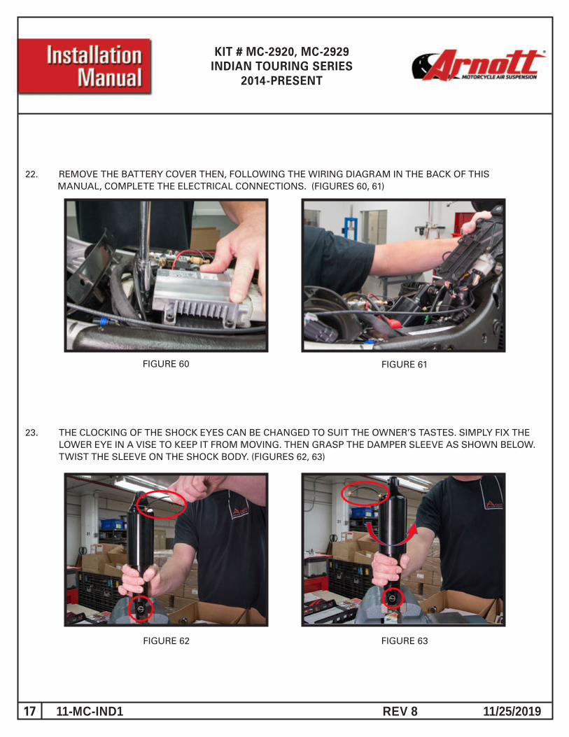
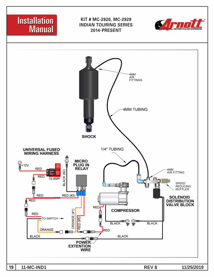
22. REMOVE THE BATTERY COVER THEN, FOLLOWING THE WIRING DIAGRAM IN THE BACK OF THIS MANUAL, COMPLETE THE ELECTRICAL CONNECTIONS. (FIGURES 60, 61)
23. THE CLOCKING OF THE SHOCK EYES CAN BE CHANGED TO SUIT THE OWNER’S TASTES. SIMPLY FIX THE LOWER EYE IN A VISE TO KEEP IT FROM MOVING. THEN GRASP THE DAMPER SLEEVE AS SHOWN BELOW. TWIST THE SLEEVE ON THE SHOCK BODY. (FIGURES 62, 63)
FIGURE 62 FIGURE 63
FIGURE 61FIGURE 60
18 REV 8 11/25/201911-MC-IND1
KIT # MC-2920, MC-2929INDIAN TOURING SERIES
2014-PRESENT
The use and installation of any Arnott Air Suspension product or kit may adversely affect or void your factory warranty. It is the responsibility of the motorcycle owner to check federal, state and local laws and ordinances before modifying or customizing his or her motorcycle. It is the exclusive and total responsibility of the motorcycle owner to determine the suitability of this product for his or her use. The user shall assume all legal obligations, personal injury risk and all liability duties and risk associated with the use of this product. Arnott Air Suspension products are designed and intended for the experienced on-road motorcyclists only and intended for closed course operation. Arnott Air Suspension products and kits are designed exclusively for OEM manufactured and equipped motorcycles with no modifications. Any installation of aftermarket or customized components may adversely affect the operation and performance of Arnott Air suspension kits and components and may void the manufacturer’s warranty. These directions are accurate at time of publication. Arnott Inc. reserves the right to revise specifications without notice.
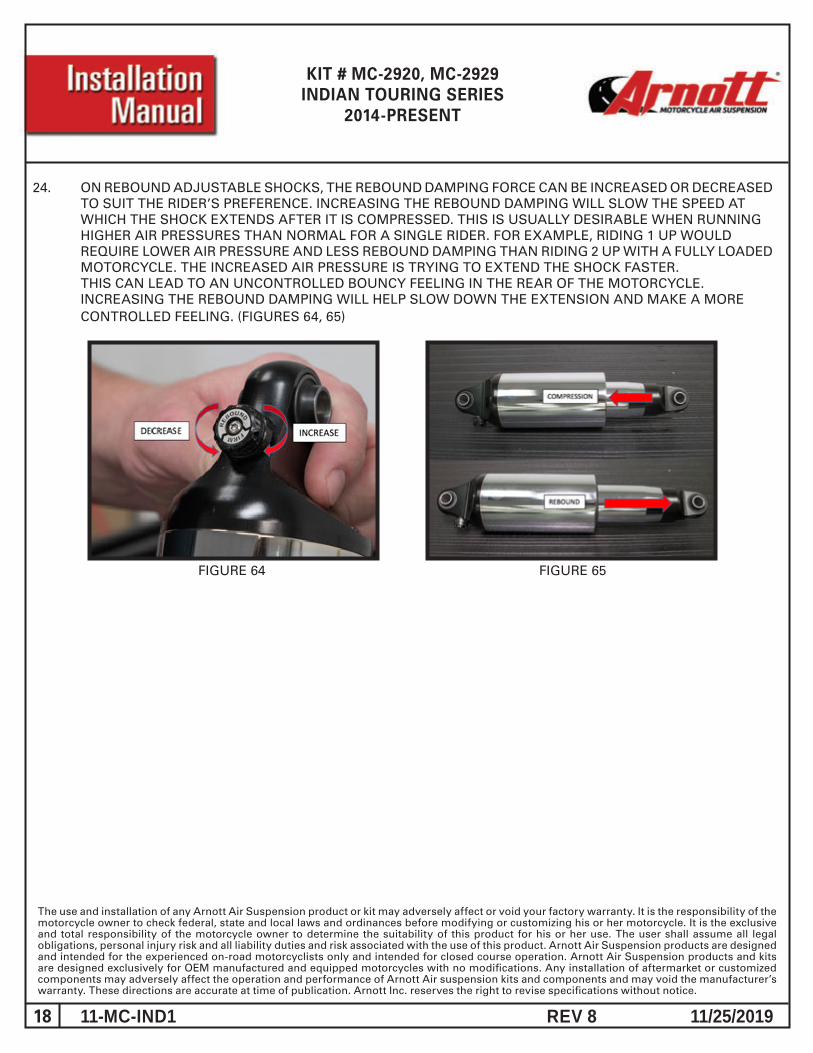
24. ON REBOUND ADJUSTABLE SHOCKS, THE REBOUND DAMPING FORCE CAN BE INCREASED OR DECREASED TO SUIT THE RIDER’S PREFERENCE. INCREASING THE REBOUND DAMPING WILL SLOW THE SPEED AT WHICH THE SHOCK EXTENDS AFTER IT IS COMPRESSED. THIS IS USUALLY DESIRABLE WHEN RUNNING HIGHER AIR PRESSURES THAN NORMAL FOR A SINGLE RIDER. FOR EXAMPLE, RIDING 1 UP WOULD REQUIRE LOWER AIR PRESSURE AND LESS REBOUND DAMPING THAN RIDING 2 UP WITH A FULLY LOADED MOTORCYCLE. THE INCREASED AIR PRESSURE IS TRYING TO EXTEND THE SHOCK FASTER. THIS CAN LEAD TO AN UNCONTROLLED BOUNCY FEELING IN THE REAR OF THE MOTORCYCLE. INCREASING THE REBOUND DAMPING WILL HELP SLOW DOWN THE EXTENSION AND MAKE A MORE CONTROLLED FEELING. (FIGURES 64, 65)
FIGURE 64 FIGURE 65
19 REV 8 11/25/201911-MC-IND1
KIT # MC-2920, MC-2929INDIAN TOURING SERIES
2014-PRESENT
20 REV 8 11/25/201911-MC-IND1
KIT # MC-2920, MC-2929INDIAN TOURING SERIES
2014-PRESENT
WEIGHT:
035-2610
KMD 4/4/08
SWITCH MOUNT ASSEMBLY
PROPRIETARY AND CONFIDENTIAL
THE INFORMATION CONTAINED IN THISDRAWING IS THE SOLE PROPERTY OFARNOTT, INC. ANY REPRODUCTION IN PART OR AS A WHOLEWITHOUT THE WRITTEN PERMISSION OFARNOTT, INC. IS PROHIBITED.
COMMENTS:
SHEET 1 OF 1
Q.A.
MFG APPR.
ENG APPR.
CHECKED
DRAWN
DATENAMEDIMENSIONS ARE IN INCHESTOLERANCES:FRACTIONALANGULAR: MACH BEND TWO PLACE DECIMAL THREE PLACE DECIMAL
NEXT ASSY USED ON
APPLICATION DO NOT SCALE DRAWING
FINISH
MATERIAL
REV.
ADWG. NO.SIZE
SCALE: NONE
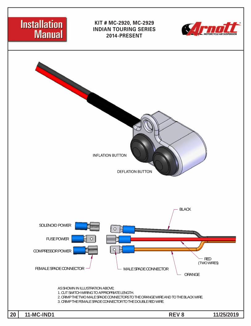
INFLATION BUTTON
DEFLATION BUTTON
SOLENOID POWER
FUSE POWER
COMPRESSOR POWER
FEMALE SPADE CONNECTOR MALE SPADE CONNECTORORANGE
RED
BLACK
(TWO WIRES)
AS SHOWN IN ILLUSTRATION ABOVE;1. CUT SWITCH WIRING TO APPROPRIATE LENGTH.2. CRIMP THE TWO MALE SPADE CONNECTORS TO THE ORANGE WIRE AND TO THE BLACK WIRE.3. CRIMP THE FEMALE SPADE CONNECTOR TO THE DOUBLE RED WIRE.