energy management consultation and training project …pdf.usaid.gov/pdf_docs/pnaca645.pdf ·...
TRANSCRIPT

RMA/IND - EMCAT - LPD - SI1
Energy Management Consultation and Training Project (EMCAT):Loan Portfolio Development Project (LPD)
Pre-Investment SurveyDirect Reduced Iron Industry (Sponge Iron)
September 1995
Prepared by: J. Feinman, consultant toResource Management Associates of Madison, Inc.
Prepared for: United States Agency for International Development (USAID)New Delhi, IndiaContract Number: 386-05127-C-00-4100-00
Resource Management Associates of Madison, Inc.202 State Street, Suite 303; Madison, Wisconsin 53703; phone (608) 283-2880; facsimile (608) 283-2881

Resource Management Associates of Madison, Inc. Page 3
Preface
This report covers energy conservation pre-investment survey activities of the Indian direct reduced iron (DRI) industry. These activities were conducted by Mr. Jerome Feinman in cooperation with M. N. Dastur & Company for Resource Management Associates of Madison, Inc. (RMA) under the Energy Management Consultation and Training Project (EMCAT). EMCAT is funded by the U.S. Agency for International Development (USAID) for which RMA serves as the prime contractor in implementing the project. Under this contract, RMA will provide energy efficiency consulting services until April 1997.
Four plants were surveyed as representative of Indian DRI plants. All results are being forwarded to Project partners and funding agencies, but proprietary information is not being shared among the surveyed plants.

Resource Management Associates of Madison, Inc. Page 4
Table of Contents
1. Executive Summary1
2. Introduction42.1 Project Description42.2 Technical Background4
3. Sunflag Iron and Steel Company (SUNFLAG), Bhandara63.1 Executive Summary63.2 Plant Description73.3 Process Description73.4 Plant Performance and Energy Consumption73.5 Areas of Potential Energy Consumption Improvement8
4. Prakash Industries Ltd. (PIL), Champa114.1 Executive Summary114.2 Plant Description124.3 Plant Performance and Energy Consumption124.4 Areas of Potential Energy Consumption Improvement14
5. Nippon Denro Ispat Limited (NDIL), Raigad155.1 Executive Summary155.2 Plant Description165.3 Plant Performance and Energy Consumption16
6. Essar Gujarat Limited (ESSAR), Hazira196.1 Executive Summary196.2 Plant Description206.3 Plant Performance and Energy Consumption20
List of Appendices
Appendix A Sample Payback CalculationAppendix BContactsAppendix CPhotographs
Resource Management Associates of Madison, Inc. Page 5
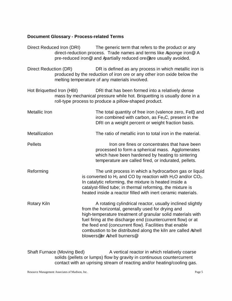
Document Glossary - Process-related Terms
Direct Reduced Iron (DRI) The generic term that refers to the product or any direct-reduction process. Trade names and terms like Asponge iron@, Apre-reduced iron@, and Apartially reduced ore@ are usually avoided.
Direct Reduction (DR) DR is defined as any process in which metallic iron is produced by the reduction of iron ore or any other iron oxide below the melting temperature of any materials involved.
Hot Briquetted Iron (HBI) DRI that has been formed into a relatively dense mass by mechanical pressure while hot. Briquetting is usually done in a roll-type process to produce a pillow-shaped product.
Metallic Iron The total quantity of free iron (valence zero, FeE) and iron combined with carbon, as Fe3C, present in the DRI on a weight percent or weight fraction basis.
Metallization The ratio of metallic iron to total iron in the material.
Pellets Iron ore fines or concentrates that have been processed to form a spherical mass. Agglomerates which have been hardened by heating to sintering temperature are called fired, or indurated, pellets.
Reforming The unit process in which a hydrocarbon gas or liquid is converted to H2 and CO by reaction with H2O and/or CO2. In catalytic reforming, the mixture is heated inside a catalyst-filled tube; in thermal reforming, the mixture is heated inside a reactor filled with inert ceramic materials.
Rotary Kiln A rotating cylindrical reactor, usually inclined slightly from the horizontal, generally used for drying and high-temperature treatment of granular solid materials with fuel firing at the discharge end (countercurrent flow) or at the feed end (concurrent flow). Facilities that enable combustion to be distributed along the kiln are called Ashell blowers@ or Ashell burners@.
Shaft Furnace (Moving Bed) A vertical reactor in which relatively coarse solids (pellets or lumps) flow by gravity in continuous countercurrent contact with an uprising stream of reacting and/or heating/cooling gas.

Resource Management Associates of Madison, Inc. Page 6
NM3 Normal Cubic Meters, the volume of a substance that would measure one cubic meter if it were brought to a temperature of 20 degrees Celsius and one atmosphere of pressure.
g/cc Grams per cubic centimeter
Document Glossary - Economics-related Terms
Electric Energy Consumption The total electric energy consumed by the direct reduction plant in converting feed to product (expressed in kWh/metric ton of product).
Energy Consumption The total energy consumed by the direct reduction plant, exclusive of the electric energy consumption, in converting feed to product (expressed in GJ/metric ton of product). Export steam and fuel should be credited.
Plant Productivity The delay-free output of product (expressed in metric tons/day). In other words, plant productivity is the instantaneous production rate of the plant (expressed as metric tons/hour multiplied by 24 hours/day).
Turnaround Time The average time to bring a plant from shutdown of a campaign (stoppage of production) to the start of the next campaign (start of production).
Plant Overall Availability The ratio of the actual time that the plant is producing product to the total time (turnaround time plus total duration), often expressed as a percentage.
Plant Capacity The annual production of the plant based on plant productivity and plant overall availability (expressed as metric tons per year) i.e.,
Plant Capacity = (Plant Productivity) ( (Plant Overall Availability) ( 365
NOTE: For the preceding four definitions to be valid (meaningful) for comparative purposes, the values should be based on sustained plant performance over several years.

Resource Management Associates of Madison, Inc. Page 7
1. Executive Summary
Four Indian direct reduced iron (DRI) plants, also known as sponge iron plants, were visited to study their operating performance. The findings were compared with the best performing plants throughout the world. From this, the objective was to determine investment opportunities necessary to improve energy utilization. The four plants which participated in the surveys were:
C Sun Flag Iron and Steel Company Limited (SUNFLAG), BhandaraC Prakash Industries Limited (PIL), ChampaC Nippon Denro Ispat Limited (NDIL), RaigadC Essar Gujarat Limited (ESSAR), Hazira
This report characterizes each plant=s performance with respect to energy consumption and identifies energy savings projects which may require bank loans to implement. The plants were selected by the Industrial Development Bank of India (IDBI). After agreeing to participate, the plants were visited by representatives of M. N. Dastur & Company, an Indian consulting firm specializing in the iron industry. This visit collected plant baseline data which greatly enhanced the site survey efficiency. Their findings were presented in a report labeled AEnergy Conservation in Sponge Iron Industries in India: Technology Pre-Assessment Report to Industrial Development Bank of India B March 1995.@
The manufacture of DRI is very energy-intensive, making energy a significant cost in production of DRI. Either coal or natural gas is the plants= primary energy source, along with electricity which is required for motor-driven equipment and lighting. The production of DRI, an intermediate step in the steel-making process, is a relatively new procedure, which makes the oldest plants only 15 years old. The plants visited are representative of the Indian DRI industry with respect to energy consumption. In the paragraphs which follow, the efficiency of energy utilization in the surveyed plants is compared to that of DRI plants in South Africa which utilize what is considered to be state-of-the-art technology. The Indian plant processes utilize state-of-the-art technology. Improvements in energy efficiency are focused on waste energy recovery and compensation for low quality coal used.
Two plants, SUNFLAG and PIL, use coal-based technology in rotary kilns. The other two plants, NDIL and ESSAR, use gas-based technology in MIDREX moving-bed shafts. Gas-based plants are inherently more energy efficient than coal-based plants; however, fuel cost and availability negate this advantage.
The results of the survey at SUNFLAG show that thermal and electrical consumption are about 30 percent higher than what has been achieved in other similar state-of-the-art plants. The thermal energy consumption can be improved by making changes in coal handling, preparation, and coal procurement procedures. Electrical
Resource Management Associates of Madison, Inc. Page 8
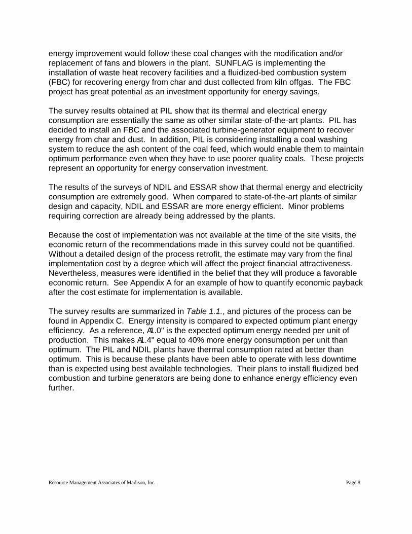
energy improvement would follow these coal changes with the modification and/or replacement of fans and blowers in the plant. SUNFLAG is implementing the installation of waste heat recovery facilities and a fluidized-bed combustion system (FBC) for recovering energy from char and dust collected from kiln offgas. The FBC project has great potential as an investment opportunity for energy savings.
The survey results obtained at PIL show that its thermal and electrical energy consumption are essentially the same as other similar state-of-the-art plants. PIL has decided to install an FBC and the associated turbine-generator equipment to recover energy from char and dust. In addition, PIL is considering installing a coal washing system to reduce the ash content of the coal feed, which would enable them to maintain optimum performance even when they have to use poorer quality coals. These projects represent an opportunity for energy conservation investment.
The results of the surveys of NDIL and ESSAR show that thermal energy and electricity consumption are extremely good. When compared to state-of-the-art plants of similar design and capacity, NDIL and ESSAR are more energy efficient. Minor problems requiring correction are already being addressed by the plants.
Because the cost of implementation was not available at the time of the site visits, the economic return of the recommendations made in this survey could not be quantified. Without a detailed design of the process retrofit, the estimate may vary from the final implementation cost by a degree which will affect the project financial attractiveness. Nevertheless, measures were identified in the belief that they will produce a favorable economic return. See Appendix A for an example of how to quantify economic payback after the cost estimate for implementation is available.
The survey results are summarized in Table 1.1., and pictures of the process can be found in Appendix C. Energy intensity is compared to expected optimum plant energy efficiency. As a reference, A1.0" is the expected optimum energy needed per unit of production. This makes A1.4" equal to 40% more energy consumption per unit than optimum. The PIL and NDIL plants have thermal consumption rated at better than optimum. This is because these plants have been able to operate with less downtime than is expected using best available technologies. Their plans to install fluidized bed combustion and turbine generators are being done to enhance energy efficiency even further.

Resource Management Associates of Madison, Inc. Page 9
Table 1.1 Comparison of Plant Energy Consumption per Unit of Production
Indian Plant/South African Plant
Optimum ThermalEnergy
Thermal Energy
Optimum Electrical Energy
Electrical Energy
Recommendations and Plans
SUNFLAG/Dunswart
1.0 1.40 1.0 1.3 Improved coal handling Fan and blower modifications Install WHRB & FBC + TG FBC + TG possible for IDBI
PIL/ISCOR 1.0 0.96 1.0 1.0 Install coal washery-new process lineInstall FBC + TG-new process line
NDIL/MIDREX 1.0 0.90 1.0 1.0 Already optimumESSAR/MIDREX 1.0 1.20 1.0 1.0 Already optimum for plant
Replacing original cooling towers- under implementation
NOTE: Please see glossary at the beginning of this report to reference abbreviations.
Resource Management Associates of Madison, Inc. Page 10
1 For a complete discussion of these aspects, refer to APre-Investment Study to IDBI, Section 2 - Direct Reduction Technology and its Status in India@, M. N. Dastur & Company Ltd., March 1995.
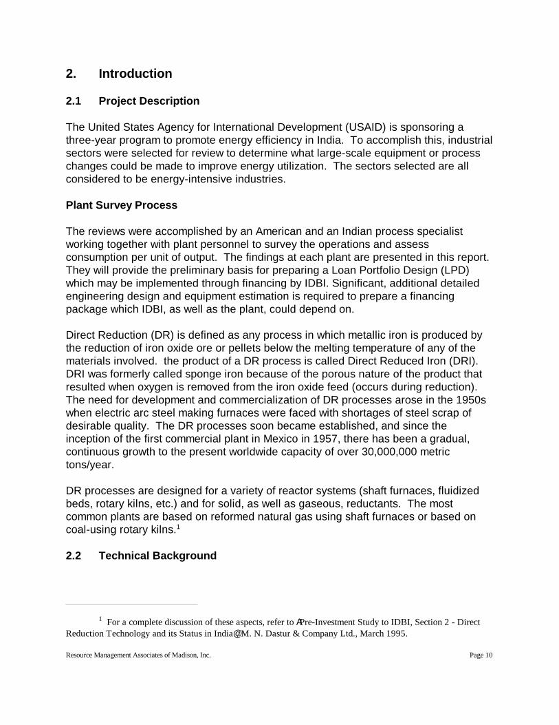
2. Introduction
2.1 Project Description
The United States Agency for International Development (USAID) is sponsoring a three-year program to promote energy efficiency in India. To accomplish this, industrial sectors were selected for review to determine what large-scale equipment or process changes could be made to improve energy utilization. The sectors selected are all considered to be energy-intensive industries.
Plant Survey Process
The reviews were accomplished by an American and an Indian process specialist working together with plant personnel to survey the operations and assess consumption per unit of output. The findings at each plant are presented in this report. They will provide the preliminary basis for preparing a Loan Portfolio Design (LPD) which may be implemented through financing by IDBI. Significant, additional detailed engineering design and equipment estimation is required to prepare a financing package which IDBI, as well as the plant, could depend on.
Direct Reduction (DR) is defined as any process in which metallic iron is produced by the reduction of iron oxide ore or pellets below the melting temperature of any of the materials involved. the product of a DR process is called Direct Reduced Iron (DRI). DRI was formerly called sponge iron because of the porous nature of the product that resulted when oxygen is removed from the iron oxide feed (occurs during reduction). The need for development and commercialization of DR processes arose in the 1950s when electric arc steel making furnaces were faced with shortages of steel scrap of desirable quality. The DR processes soon became established, and since the inception of the first commercial plant in Mexico in 1957, there has been a gradual, continuous growth to the present worldwide capacity of over 30,000,000 metric tons/year.
DR processes are designed for a variety of reactor systems (shaft furnaces, fluidized beds, rotary kilns, etc.) and for solid, as well as gaseous, reductants. The most common plants are based on reformed natural gas using shaft furnaces or based on coal-using rotary kilns.1
2.2 Technical Background

Resource Management Associates of Madison, Inc. Page 11
The first commercial plant production of DRI in India was a coal-based process installed by Orissa Sponge Iron Ltd, in 1983. The first Indian gas-based DRI plant was installed by ESSAR in Hazira in 1990. To date, twenty-three coal-based DRI plants with a total capacity of 1,960,000 metric tons/year, and five gas-based DRI plants with a total capacity of 3,070,000 metric tons/year, have been installed, making India a world leader in operating DRI capacity. All of this capacity is essentially Astate-of-the-art@ which precludes basic technology changes and limits product handling facilities and facilities to recover energy from process effluents. In addition, replacement of some heat exchangers might be justified, but would probably not fall within the magnitude of an LPD. These recommendations will be noted for purposes of information.
Each of the following four sections describes one of the plants surveyed. A list of contact persons can be found in Appendix B.

Resource Management Associates of Madison, Inc. Page 12
3. Sunflag Iron and Steel Company (SUNFLAG), Bhandara
3.1 Executive Summary
The Sunflag Iron and Steel Company (SUNFLAG) is located in Bhandara. The energy survey focused on its Direct Reduced Iron (DRI) facility which was commissioned in 1989.
DRI is used as a feedstock in electric arc furnaces. Shortages of scrap iron necessitate production of a metallic iron source. DRI was previously called sponge iron because of its porous character.
DRI plants are typically coal- or natural gas-based processes. SUNFLAG is a coal-based facility. The reduction kiln is the primary consumer of coal. Electricity is the next largest energy source with motors and lighting being the primary consumers. This plant is representative of coal-based plants in India. Inefficiencies which arise in the plant are due to coal handling, preparation, and procurement deficiencies.
Opportunities for energy conservation include:
C Provision of covered coal storage to minimize moisture content and improve injectability
C Procurement of reliable, good quality coal
C Modification of the coal injection system
C Improvement of the draft for transmission efficiency
C Provision of variable speed drives for the kiln discharge fan
C Modification of blowers for kiln offgas to optimize efficiency
Modifying coal handling, procurement, and injection has the potential of reducing the thermal load from 25 GJ/metric ton of DRI to between 15 and 19 GJ/metric ton of DRI. Given a 150,000 metric-ton-per-year capacity and a 79% capacity utilization, potential energy savings range from 702,000 to 1,170,000 GJ/year. At Rs. 1,400 ($45) per metric ton of coal, annual savings could range from 4 to 7 crore ($1.3 million to $2.3 million).
Based on comparison to similar facilities, electrical energy has the potential of being reduced by 20% to 25%. Given 100 kWh per metric one of existing electrical consumption, the annual savings potential is estimated to range from 2,340,000 to 2,925,000 kWh. Priced at Rs. 4 ($0.129) per kWh, this is savings is valued at Rs. 1 crore to 1.2 crore ($300,000 B $375,000) per year.

Resource Management Associates of Madison, Inc. Page 13
3.2 Plant Description
The Sunflag Iron and Steel Company (SUNFLAG) is located in Bhandara. The facility specializes in making DRI utilizing the CODIR process.
Coal is the main energy source used in the plant, with electricity used to support motors and lighting. The coal is supplied by multiple coal suppliers (depending on availability and price). The reduction kiln is the main consumer of coal.
The plant was designed according to the most recent standards and is based on state-of-the-art technology. The plant is representative of coal-based plants in India. Inefficiencies which arise in the plant are due to coal handling, preparation, and procurement deficiencies. Opportunities for efficiency improvements are identified in Section 3.5.
3.3 Process Description
The CODIR process at SUNFLAG is carried out in a refractory-lined rotary kiln that rotates on an inclined axis and is continuously fed at a controlled rate with sized iron ore, dolomite for sulfur absorption, and coal for reduction and energy. A schematic flow sheet of the plant is shown in Figure 3.1., and pictures of the process are in appendix C. As the raw material charge moves to the discharge end, it is progressively heated to about 1000EC by the hot kiln gas being generated from partial combustion of coal with air in a burner at the discharge end of the kiln. The kiln is fitted with six shell-mounted fans that supply air to burner tubes which enter through the shell and discharge air along the kiln center line. This added air burns both CO formed during chemical reduction and volatiles from the coal and helps maintain the kiln temperature at between 905EC and 1050EC over about 60% of its length. This process enables chemical reduction to achieve a high degree of metallization.
The solids leaving the kiln are cooled by direct water sprays in a rotary cooler. The DRI is then separated from the ash and expended dolomite by screening and magnetic separation. The kiln offgas passes through a dust-settling chamber and an after-burning chamber. This chamber burns the remaining combustibles prior to scrubbing in a conditioning tower, final cleaning in an electrostatic precipitator, and exhausting to the atmosphere through an induced draft fan and clean gas stack.
The kiln is also fitted with an injection system at the discharge end enabling up to 70 % of the coal needed for the process to be blown in along the last half of the kiln=s length. The idea is to allow coal volatiles to be utilized for chemical reduction, as well as heating energy, by releasing them in the high-temperature zone instead of closer to the feed end. In this way, the volume of coal needed to provide chemical carbon is minimized.
3.4 Plant Performance and Energy Consumption
The SUNFLAG plant has a rated capacity of 150,000 metric tons/year. Although a record

Resource Management Associates of Madison, Inc. Page 14
production of 15,680 metric tons was achieved in November 1993, capacity utilization has been 78% during the past two years. Campaigns as long as 150 days have been achieved, however, these have been rare, with the average campaign lasting about 70 days. The main reason for premature process shutdown is the formation of heavy accretions on the kiln walls in the high-temperature regions near the kiln discharge. These accretions, which lead to refractory damage and blockages in the kiln discharge, are promoted by upsets in operation that lead to hot spots and localized charge overheating. Premature shutdowns lead to periods of high energy use and low production. This creates a higher energy consumption per unit of output.
The thermal energy consumption at SUNFLAG is about 25 GJ/metric ton DRI. In contrast, the thermal energy consumption in the CODIR plant at Dunswart Iron and Steel Works in South Africa is reported to be in the range of 15 to 19 GJ/metric ton DRI. The Dunswart plant, which started operations in 1974, has a rated capacity of 150,000 metric tons/year when operating on reducible ores. The high thermal energy consumption at SUNFLAG is attributed to the fact that SUNFLAG has been operating on poorer quality coal as shown below:
Dunswart SUNFLAG
Fixed carbon, % 54 45Volatile matter, % 30 22Ash, % 11 22Moisture, % 5 10
The ash and moisture content at SUNFLAG is considerably higher than Dunswart and imposes a proportionally higher thermal load in order to heat the inert ash and to vaporize and heat the moisture. Dunswart was successful in decreasing their thermal energy consumption by about 25%, to the present levels, when the coal injection facilities at the discharge end of the kiln were installed in 1981-82. The injection facilities at SUNFLAG have not been used effectively because the coal size and moisture content have mitigated against proper injection. The optimum benefits of injection are, therefore, not obtained.
The total electrical energy consumption at SUNFLAG is 100 kWh/metric ton DRI, which is high compared with the representative international range of 75 to 80 kWh/metric ton DRI. Opportunities for improving the electrical energy consumption at SUNFLAG will be discussed in the following section.
3.5 Areas of Potential Energy Consumption Improvement
Improvements in thermal energy consumption at SUNFLAG will depend entirely on making the appropriate changes in coal handling and preparation to enable effective operation of the injection facilities, at the kiln discharge, at the recommended level of 50 to 70 %. Possible modifications include:C Additional covered coal storage to minimize moisture content and improve injectability

Resource Management Associates of Madison, Inc. Page 15
C Improvement of coal procurement procedures to provide the plant with a reliable supply of good quality coal
C Injection system modifications including installation of a star valve feeder to replace the existing Brieden machine feeding arrangement
Plant personnel suggested the following areas where electrical energy consumption could be decreased:
C The induced draft fan has a drive coupling that results in inefficient transfer of kinetic energy from the motor to the fan. It could be replaced with a higher efficiency transmission system.
C The primary air blower, supplying air to the kiln discharge, is providing 5,000 to 7,000 NM3/hour during normal operation. This blower is rated at 32,000 NM3/hour for start-up and is, therefore, not operating at peak efficiency during normal operation. Either installing a second fan of lower capacity, or installing a variable speed drive could reduce energy consumption.
C Both the primary and secondary blowers providing air for post-combustion of the kiln offgas have substantially more capacity than needed and are, therefore, not operating at peak efficiency. Modifying these blowers would also result in electrical energy savings.
Although these modifications would improve the electrical energy consumption, more substantial improvements will be obtained when operations closer to the rated capacity are achieved by improving coal quality and utilization.

Figure 3.1 Flow Sheet of CODIR Process

Resource Management Associates of Madison, Inc. Page 17
4. Prakash Industries Ltd. (PIL), Champa
4.1 Executive Summary
The Prakesh Industries Limited (PIL) plant is located in Champa. The facility specializes in producing Direct Reduced Iron (DRI) for the steel-making industry and was commissioned in 1993.
DRI is used as a feedstock in electric arc furnaces. DRI was previously called sponge iron because of its porous character. Shortages of scrap iron necessitate production of a metallic iron source for use in electric arc furnaces for steel making.
DRI plants are typically coal- or natural gas-based processes. PIL is a coal-based facility. The reduction kiln is the primary consumer of coal. Electricity is the next largest energy source, with motors and lighting being the main consumers. This plant is typical in construction, although, because of extraordinary operation, it is superior in energy consumption performance.
Energy efficiency is optimum at this plant, because of the strict control of both iron ore and coal quality, as well as the excellent operation of its raw material handling and preparation equipment.
Presently, PIL is installing a second kiln rated at 150,000 Mtons of DRI per year. Funding to implement energy efficiency measures on the new process line will be necessary. This project will include a waste heat recovery boiler and two 7.5-MW turbine generators installed to match those present in the existing kiln. In addition, a coal washing system is being considered to maintain optimum performance when using poor quality coals.
PIL is also investigating the recovery of dust from kiln gas, nonmagnetics from cooler discharge, and coal fines from coal screening. They would burn these materials in a fluidized bed combustor and generate electricity with turbine generator equipment.
In general, the energy recovery concepts being pursued by the plant have energy conservation merit. Specific economic returns cannot be reasonably estimated without a detailed design of implementation. Implementation of these energy conservation measures will be of a magnitude requiring external financing.

Resource Management Associates of Madison, Inc. Page 18
2 Refer to Section 2, ADirect Reduction Technology and its Status in India,@ Pre-Investment Study for Energy Conservation in Sponge Iron Industries in India, M. N. Dastur & Co. Ltd., March 1995.
4.2 Plant Description
The Prakash Industries Limited (PIL) plant is located in Champa. The facility specializes in producing DRI for steel-making. The reduction kiln at PIL is designed according to the SL/RN2 (promoted by Lurgi) and is very similar to the system used by the other coal-based plant surveyed. A schematic flow sheet of the plant is shown in Figure 4.1., and plant process pictures can be found in appendix C. The major differences between the two plants are that at PIL, the product is cooled by indirect water sprays on the outside of the cooler, and the kiln offgas is cooled in a waste heat recover boiler. Indirect product cooling requires a longer cooler than does direct cooling. However, there is no loss of metallization during indirect cooling. In the direct spray cooler, the loss of 0.5 to 1.0 percent metallization by reoxidation offsets the economic advantage of the smaller cooler. At PIL, the steam created in the waste heat recovery boiler is used to generate about 6 MW of power in one of two turbine-generator sets (one standby). In other respects, the two plants are essentially the same.
4.3 Plant Performance and Energy Consumption
The PIL plant has a rated capacity of 150,000 metric tons/year and has performed at or above that level since commissioning in November 1994. During the survey visit on June 9, 1995, PIL reached day 210 of their fourth campaign. They operated at full-rated capacity in 1994 and expect to do even better this year. The coal consumption ranges from 950 to 1,000 kg/metric ton DRI as charged. This is equivalent to an energy consumption of 21 to 23 GJ/metric ton DRI, using 23 GJ/metric ton of Indian sub-bituminous coal.
The SL/RN kilns at the South African Steel Corporation=s (ISCOR) Vanderbijlpark works, commissioned in 1984 represent the world standard for these plants and are the same size and capacity as the PIL plant. The kilns at ISCOR are also equipped with waste heat recovery boilers. The total production at ISCOR is about 400 days. Coal consumption at ISCOR is reported to be 800 to 900 kg/metric ton of DRI using 28 GJ/metric ton for South African sub-bituminous coal, equivalent to an energy consumption of 22 to 25 GJ/metric ton DRI. The slightly higher energy consumption at ISCOR may be due to the lower reducibility of the Sishen ore they use, as compared to other Indian ores.
It is clear that PIL has achieved optimum rated performance in less than two years of operation. This accomplishment is partly the result of strict control of the quality of iron ore and coal used in the plant and partly because of the operation of both their raw material handling and preparation equipment. To achieve this same level of energy efficiency in their new installation, the next section identifies energy saving opportunities that can be utilized.

Figure 4.1 Flow Sheet of SL/RN Process

Resource Management Associates of Madison, Inc. Page 20
4.4 Areas of Potential Energy Consumption Improvement
PIL is presently installing a second kiln rated at 150,000 metric tons DRI/year that will also incorporate a waste heat recovery boiler and turbine generators at 7.5 MW. PIL is also considering the installation of a coal washing system which will reduce the ash content of the coal feed. This would enable them to maintain optimum performance even when they have to use poorer quality coals.
Along with dust collected from the kiln offgas, the coal washery rejects both nonmagnetics from the cooler discharge and fines generated during coal screening. This material represents a substantial energy source that should be used in the plant. PIL has decided to install a fluidized-bed combustor (FBC) and associated turbine-generator equipment to recover this energy. They have commissioned a study to estimate the power generation potential of this system and expect about 5 MW of power to be available. These projects will require large-scale energy conservation financing. As the time of the plant survey, financing arrangements had not been made.
It was suggested to PIL to separate the ash portion of the nonmagnetic product cooler discharge. This could be done in a char recovery system (e.g., an air flotation unit). This would result in better utilization of the heating value of the feed to the FBC. This should be considered when the capacity of the FBC is established. PIL expressed interest in this concept.
A detailed study must be made of the equipment and operating requirements for these projects to establish their economic potential. Because of the variability in installation requirements, a payback estimate, prior to implementation design, would not be reliable. Implementation of the FBC and coal washery is scheduled to be completed by the end of 1997.

Resource Management Associates of Madison, Inc. Page 21
5. Nippon Denro Ispat Limited (NDIL), Raigad
5.1 Executive Summary
The Nippon Denro Ispat Limited (NDIL) plant is located in Raigad. The facility specializes in producing Direct Reduced Iron (DRI) for the steel-making industry. It was commissioned in September 1991.
DRI is used as a feedstock in electric arc furnaces. It was previously called sponge iron because of its porous character. Shortages of scrap iron necessitate production of a metallic iron source for use in electric are furnace steel making operations.
DRI plants are typically coal- or natural gas-based processes. NDIL is a natural gas-based facility. Natural gas is used for its chemical components as well as for heating the gaseous chemical components. Electricity is the next largest source of energy source, with motors and lighting being the primary consumers.
The NDIL plant is a showcase facility. It operates at 9 GJ per metric ton of DRI produced, compared to the 10 GJ per metric ton of DRI produced expected in a typical MIDREX process plant.
Electrical consumption has been minimized in the plant process through the use of high-voltage motors, proper sizing of motors and compressors, and close monitoring of consumption to ensure identification of efficiency problems.
Given the plant design and present operation, no economically viable energy conservation measures are recommended.

Resource Management Associates of Madison, Inc. Page 22
5.2 Plant Description
The NDIL plant is located in Raigad. The facility specializes in producing DRI for the steel-making industry.
Energy sources used in the plant include natural gas and electricity. Natural gas is the main energy used in the process. It is used in the reformer and shaft reducer portions of the plant. Electricity is used for process support equipment and lighting.
The NDIL plant at Raigad is based on a one-million-metric ton-per-year module known as a AMegaMod@. The MegaMod is the basis used in the MIDREX DRI-making process. A schematic flow sheet of the plant is shown in Figure 5.1., and pictures of the process can be found in appendix C. The major components of the plant are the reduction shaft and the natural gas reformer with associated heat exchange equipment. The shaft is fed at the top with a mixture of lump ore and ore pellets. Reduction takes place as the charge descends in counter-current contact with hot reducing gas. This gas is generated by catalytic reforming of natural gas with a portion of the reducer offgas to produce gas containing about 55 % CO and 33% H2 at temperatures between 800EC and 900EC. The hot DRI is cooled to near ambient in the lower section of the shaft by means of inert cooling gas which circulates in a closed loop. The spent reducing gas leaves the shaft at about 400EC and is cleaned in a scrubber; two-thirds of this gas is mixed with natural gas as feed to the reformer, and the remainder is burned as a fuel to produce heat in the reformer.
5.3 Plant Performance and Energy Consumption
The NDIL plant has achieved more than its rated capacity of 133 metric tons/hour for short periods since commissioning in September 1994. (Its maximum was 176 metric tons/hour.) Sustained operation at this level has been difficult to achieve because of frequent plant shutdowns caused by expansion bellows failures in the reformer. Replacements are being obtained from Indian manufacturers, and the problem is expected to be eliminated shortly. Plant personnel reported that they plan to ultimately increase production to 200 metric tons/hour. However, they will need to add a second reformer bay to provide additional reducing gas.
NDIL has implemented a system for coating the feed pellets and ore with lime. This enables operation at higher gas inlet temperatures, without sticking or clustering. This also increases the capacity of the shaft with an accompanying decrease in energy consumption per metric ton of DRI produced.
The energy consumption of 9 GJ/metric ton of DRI at NDIL is lower than is being obtained at other state-of-the-art MIDREX plants. (The standard is about 10 GJ per metric ton of DRI.) At NDIL, the gas recuperation system that preheats the reducer offgas has an additional tube bundle that other typical MIDREX plants. This produces a higher reducer offgas temperature prior to it being burned.

Resource Management Associates of Madison, Inc. Page 23
The only possibility for reducing the energy consumption in this plant would be installation of an additional exchanger to recover energy from the reducer offgas (which exits at about 400EC). The benefits of this modification appear to have only marginal economic benefit. Therefore, pursuit of this modification is not recommended.
The electric power supply for the NDIL plant was designed with capacitor banks that provide a power factor of 0.99. In addition, high-voltage electric motors are used, to the extent possible, so there is no margin for improvement. The plant uses a tri-vector meter that gives close monitoring of the energy load and maximum efficiency. Motor sizes and compressors were selected with a built-in margin to provide maximum reliability and operation at 200 metric tons/hour. The design electricity consumption is 105 kWh/metric ton DRI, and the plant is already achieving 92 to 95 kWh/metric ton DRI.
In summary, the thermal energy and electricity consumption at NDIL is optimum.

Figure 5.1 Flow Sheet of MIDREX Process

Resource Management Associates of Madison, Inc. Page 25
6. Essar Gujarat Limited (ESSAR), Hazira
6.1 Executive Summary
The Essar Gujarat Limited (ESSAR) plant is located in Hazira. The plant consists of three MIDREX process modules, which were commissioned in September 1994.
Direct Reduced Iron (DRI) is used as a feedstock in electric arc furnaces. DRI was previously called sponge iron because of its porous character. Shortages of scrap iron necessitate production of a metallic iron source to be used in electric arc furnace steel making operations.
DRI plants are typically coal- or natural gas-based processes. ESSAR is a natural gas-based facility. Natural gas is used for its chemical components, as well as for heating the gaseous chemical components. Electricity is the next largest energy source utilized. Motors and lighting are the main consumption areas.
The ESSAR plant presently has problems with its cooling towers. The towers were obtained from a plant outside India, and are not suitable for the Indian climate. Because the towers under-cool, energy inefficiencies appear throughout the process. The plant realizes this and plans to replace the towers soon.
The only energy efficiency opportunity identified was to recover heat from the reformer flue gas exhaust. Unfortunately, the ESSAR modules are not suited to install additional heat exchange equipment. Because of the additional implementation cost, this concept is not recommended for follow-up. The operation and energy utilization at the ESSAR facility are as expected. Aside from the planned cooling towers upgrade, no economically viable opportunities to improve process energy efficiency exist.

Resource Management Associates of Madison, Inc. Page 26
6.2 Plant Description
The ESSAR plant is located in Hazira. The plant, which operates three MIDREX modules, specializes in the production of DRI in the form of dense, pillow-shaped briquettes which are stable for shipping and storage.
Energy sources used in the plant include natural gas and electricity. Natural gas is the main energy used in the process. It is used in the reformer and shaft reducer portions of the plant. Electricity is used for electric motor-driven process support equipment and lighting.
The three MIDREX modules at ESSAR are designed to produce hot briquetted iron (HBI). They discharge shaft product directly to briquetting presses under the reduction shaft as shown in Figure 6.1. The ESSAR modules do not incorporate the heat exchanger in the reformer flue gas recuperation system which is included in the MegaMod plant at the other natural gas-based plant surveyed.
6.3 Plant Performance and Energy Consumption
The ESSAR plant has consistently operated at a nominal 100 % of rated capacity during 1993 and 1994, with record production of 1,436,000 metric tons/year compared with the design productivity of 1,320,000 metric tons/year. The HBI are high quality with a metallization above 90%, carbon content of 1.2 % (" 0.3%), and a target density of 5.0 g/cc.
The energy consumption at ESSAR is reported to be in the range of 11.3 to 12.2 GJ/metric ton DRI and the electric power consumption is about 136 kWh/metric ton DRI. These consumption figures are somewhat higher than the comparable values for the HBI plant at SGI, Malaysia.
One reason for this higher consumption level is the installed cooling towers for modules 1 and 2 which were obtained from the original plant at Emden and are not suitable for India conditions. Power consumption is high in the cooling towers= induced-draft fans. This leads to a higher return water temperature causing excessive moisture carryover in the top gas fuel. This additional moisture increases reformer flue gas volume and results in a loss of thermal energy as well as higher power consumption in the flue gas handling section. The cooling towers will be replaced shortly with towers designed for Indian conditions.
After recuperation, the reformer flue gas is exhausted at 300EC to 400EC and could provide additional energy for recovery. However, the ESSAR modules are not suited to accommodate additional exchange equipment, so this is not a practical option.
In summary, the process energy consumption at ESSAR is optimum for the design of these modules. No opportunities for significant improvement, once the existing cooling towers are replaced, are recommended.

Figure 6.1 Flow Sheet of MIDREX Process for Hot Briquetted Iron

Resource Management Associates of Madison, Inc. Page 28

Appendix ASample Payback Calculation
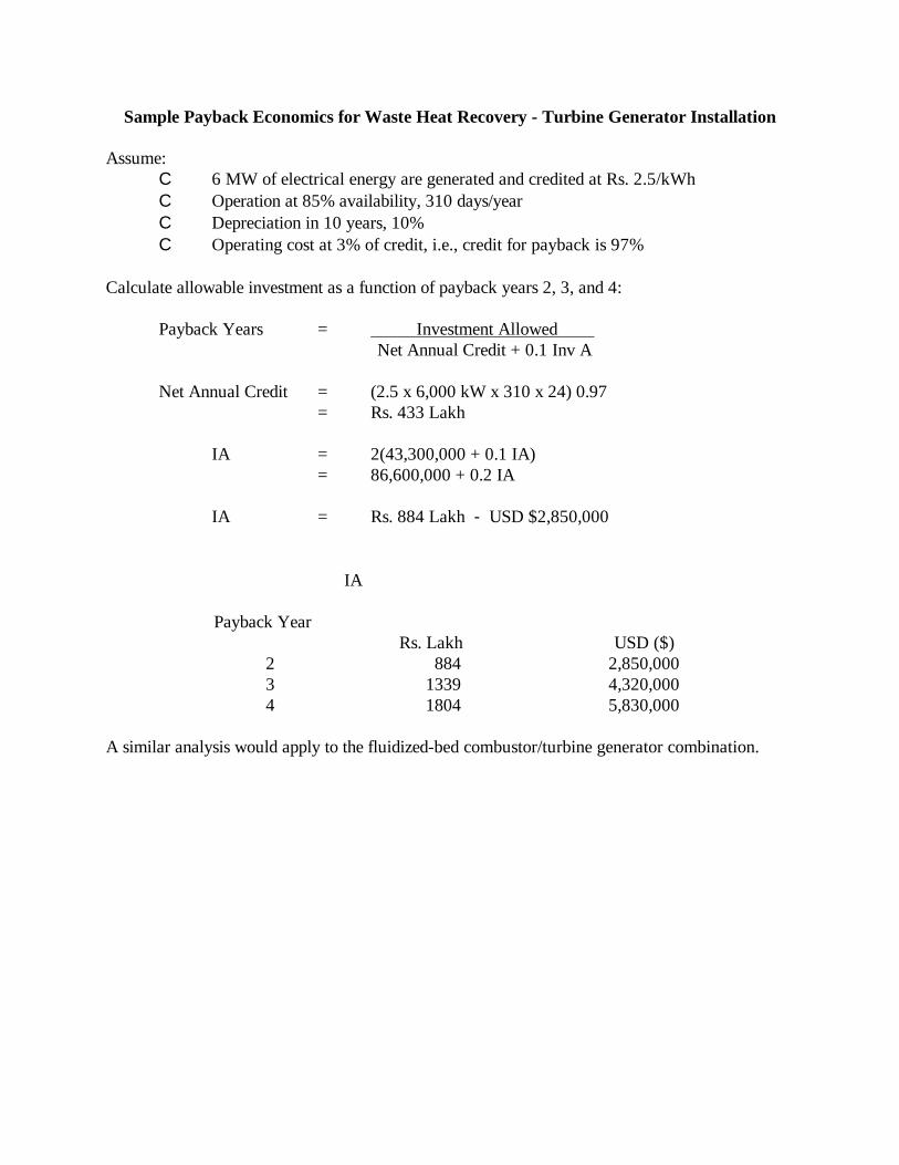
Sample Payback Economics for Waste Heat Recovery - Turbine Generator Installation
Assume:C 6 MW of electrical energy are generated and credited at Rs. 2.5/kWhC Operation at 85% availability, 310 days/yearC Depreciation in 10 years, 10%C Operating cost at 3% of credit, i.e., credit for payback is 97%
Calculate allowable investment as a function of payback years 2, 3, and 4:
Payback Years = Investment Allowed Net Annual Credit + 0.1 Inv A
Net Annual Credit = (2.5 x 6,000 kW x 310 x 24) 0.97= Rs. 433 Lakh
IA = 2(43,300,000 + 0.1 IA)= 86,600,000 + 0.2 IA
IA = Rs. 884 Lakh - USD $2,850,000
Payback Year
IA
Rs. Lakh USD ($)2 884 2,850,0003 1339 4,320,0004 1804 5,830,000
A similar analysis would apply to the fluidized-bed combustor/turbine generator combination.

Appendix BContacts

Sun Flag Iron and Steel Company, Ltd.P.O. Bhandara RoadBhandara 441 905
Mr. D. Singh, Executive DirectorMr. R. L. Piplani, General Manager - Direct ReductionMr. S. P. Dash, Process Manager - Direct Reduction
Phone: (07-184) 8551 - 8555Fax: (07-184) 4263
Prakash Industries, Ltd.Champa 495 671 (Dist. Bilaspur, M.P.)
Mr. D. P. Singh, Sr. General Manager (Project)Mr. Haripal Singh, General ManagerMr. V. K. Modi, Engineer - Mechanical
Phone: (07-819) 44293, 44294, 44296, 45100Fax: (07-819) 45101
Nippon Denro Ispat, Ltd.Dharamtar - DolviTaluka - Pen Dist.Raigad 402107
Mr. M. L. Garg, General Manager - Electrical and InstitutionalMr. R. Mendonca, Assistant General Manager - ProductionMr. P.A. Naidu, Plant Process Engineer
Phone: (021-435) 2426, 2757, 2875, 3013, 3032Fax: (021-435) 2637, 3004, 3006
Essar Gujarat, Ltd.Hazira 394270 (Dist. Surat)
Mr. A. Takoo, Assistant General ManagerMr. A. Shah, Control Room Chief (Shift)

Appendix CPhotographs
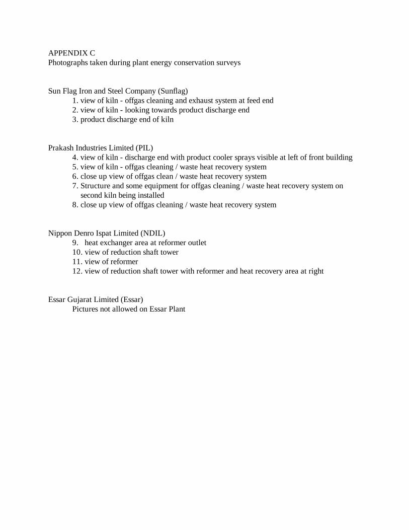
APPENDIX CPhotographs taken during plant energy conservation surveys
Sun Flag Iron and Steel Company (Sunflag)1. view of kiln - offgas cleaning and exhaust system at feed end2. view of kiln - looking towards product discharge end3. product discharge end of kiln
Prakash Industries Limited (PIL)4. view of kiln - discharge end with product cooler sprays visible at left of front building5. view of kiln - offgas cleaning / waste heat recovery system6. close up view of offgas clean / waste heat recovery system7. Structure and some equipment for offgas cleaning / waste heat recovery system on second kiln being installed8. close up view of offgas cleaning / waste heat recovery system
Nippon Denro Ispat Limited (NDIL)9. heat exchanger area at reformer outlet10. view of reduction shaft tower11. view of reformer 12. view of reduction shaft tower with reformer and heat recovery area at right
Essar Gujarat Limited (Essar)Pictures not allowed on Essar Plant

Sun Flag Iron and Steel Company (Sunflag)
1. view of kiln - offgas cleaning and exhaust system at feed end

2. view of kiln - looking towards product discharge end
3. product discharge end of kiln

4. view of kiln with offgas system at rear left

Prakash Industries Limited (PIL)
1. view of kiln - discharge end with product cooler sprays visible at left of front building

2. view of kiln - offgas cleaning / waste heat recovery system
3. close up view of offgas clean / waste heat recovery system

4. Structure and some equipment for offgas cleaning / waste heat recovery system on second kiln being installed
Nippon Denro Ispat Limited (NDIL)
1. heat exchanger area at reformer outlet

2. view of reduction shaft tower
3. view of reformer

4. view of reduction shaft tower with reformer and heat recovery area at right

Essar Gujarat Limited
Photographs not allowed at this plant