enterprise network test strategies for network ... network test... · 1 enterprise network test...
TRANSCRIPT

1
Enterprise Network Test Strategies for Network Availability and Performance
A SitaramaiahDirector
Fluke Networks India

2
Why is Enterprise Network Testing becoming increasingly important?
• IT is increasingly deployed by enterprises– Becoming a key competitive differentiator– Being deployed as Customer satisfaction is means to
customer retention• Applications are becoming more and more Web and IP
enabled• Convergence of Voice, data and Video on Network is
enabling collaboration to ensure faster and better response to customer needs
• ROI on investment in IT is being more demanded by Business Managers – alignment of business and IT objectives is more imperative
like never before

3
#1 - Networks Never Go Slower• Plan for higher speeds, increased throughput, reduced
response time
#2 - Networks Never Get Smaller• Plan for more users, more traffic, more capacity, • Integrate customers, supply chain
#3 - Networks Never Stay the Same• Plan for flexibility, reconfiguration, manageability
Three Laws of Networking

4
A Simple framework for Enterprise Network Test
• Troubleshooting approach• Aimed at front-end network engineers responsible for network troubleshooting and
auditing to help recover from problems• A reactive approach to network management• Need to equip network engineers with tools to troubleshoot physical layer (copper,
optical fiber and wireless) as well as logical (Data link and Network layer) layer issues
• Network Analysis and Monitoring approach• Aimed at Network Managers who plan and provide for Network performance• A proactive approach to Network management• Aims to “prove it is not the network”
• SLA focused approach to Enterprise Performance Management• Aimed at CIOs and Network Managers to ensure availability and delivery of
applications over enterprise networks• Service / SLA focused approach• Goes beyond traditional practice of ensuring network availability / uptime

5
A simple framework for Enterprise Network Test
Net
wor
k
Net
wor
k +
App
licat
ion
Availa
bility
Performan
ce
Traditional
Focus of Enterprise
Network Test

6
Core
Distribution
Edge
Wan Links
Enterprise Customers want to know• How can I make informed decisions on upgrades?
• What is normal on my network?
• Is it a network or server or application problem?
• Where is the traffic and Who is causing it?
• What do I need to Qualify when I deploy new technologies?
•POE, 1G at desktop or 10G Ethernet in backbone, MPLS
Traditional DCI / SI focus in India on Enterprise testing
• LAN Cabling Certification driven by Cabling OEM Warranty
• Cable Plant and Test result documentation
• Network Turn-up is a thankless job
• No prevalent LAN Acceptance testing practices
• AMCs focus on reacting to and fixing breaks
Availability Vs. Performance
MPLS
IP
Challenge
Data Center

7
Enterprise Network Test

8
LAN Media test strategies

9
Levels of Field Testing – Assuring Copper Cabling Systems Performance
Verification– The installed link meets basic continuity requirements– Does not imply any bandwidth or transmission quality
measureQualification
– The installed cabling link successfully transmits data using a specific network technology(i.e. 10GBASE-TX)
– Does not imply compliance with technologies other than the one used in the test
These levels do not deliver the assurance and confidence of the certification test

10
Levels of Field Testing – Assuring Copper Cabling Systems Performance Certification
– The definition of performance and the level (“category”) of performance is defined by industry standards • TIA-568-B defines Cat 5e, Cat 6• ISO 11801 and ISO/IEC 61935 define Class C, D , E, EA
and F– The installed cabling link meets the transmission
performance criteria as defined by the applicable industry standard
– The tests are conducted and test results are documented and reported in compliance with the standard

11
Network Technology and Certification Category
Network Technology
Data Rate Minimum required link category
10BASE-T 10 Mb/s Ethernet Cat 3 / Class C
100BASE-T4 100 Mb/s Ethernet (4-wire) Cat 3 / Class C
100VG-AnyLan 100 Mb/s Cat 3 / Class C
Token Ring 4 Mb/s Cat 3 / Class C
100BASE-TX 100 Mb/s Ethernet (2-wire) Cat 5 / Class D:2000
ATM-155 155 Mb/s Cat 5 / Class D:2000
Token Ring 16 Mb/s Cat 5 / Class D:2000
1000BASE-T 1 Gb/s Ethernet Cat 5e / Class D:2002
10GBASE-T 10 Gb/s Ethernet Cat 6 / Class E orCat 6A / Class EA

12
Cabling Requirements for 10GBASE-T
• The signal-to-noise analysis is complex and consists of two types of disturbances:
• ‘In-channel’ disturbances – Initially set to ISO/IEC 11801 Class E limits extended to 500 MHz(Class E/Cat 6 defined from 1 to 250 MHz)
• ‘Between-Channel’ disturbances for Crosstalk referred to as “Alien Crosstalk”
• Proposed cabling specifications:– TIA-TSB-155– Standard for “Augmented Cat 6” (Cat 6A) TIA-568-B.2-10

13
Alien Crosstalk
• Crosstalk between wire-pairs in adjacent cables • General rules:
– The effect is due in first instanceby proximity
– This crosstalk is worst betweenwire-pairs with the sametwist rate
– The effect is greater for pairswith a lower twist rate
– Impact increases with the distanceover which the cables run in parallel
– Impact increases with the frequency ofthe transmitted signals

14
Transmit
Receive
Workstation
Transmit
Receive
LANEquipmentSignal
External Noise from adjacent cables
Attenuated Signal
NEXT
Alien Crosstalk Is An External Noise Source
• Signal strength: measured by “Insertion Loss” • Alien Crosstalk: An external source to NEXT, FEXT and RL

15
Two-Tier Testing for Optical Fiber Cabling Systems
Per TSB-140 Additional Guidelines For Field-Testing Length, Loss And Polarity Of Optical Fiber Cabling Systems(Approved by TR-42 in February 2004)
• Tier 1: OLTS (Optical Loss Test Set)– Conforms to TIA-526-14A and TIA-526-7– Most closely simulates system– Measures the total loss of a fiber channel– Verify polarity using OLTS or VFL
• Tier 2: OTDR Trace– Can show segment lengths, connector locations & losses, and losses not at a
connector– Provides evidence that cable is installed without degrading events (e.g., bends,
connection, splice)– Can do single-ended testing

16
Test Example: Tier 1 (OLTS)
Horizontal Cables
Backbone Cables
TR
MC
• 50/125 μm cabling (laser optimized)• 130 m backbone cable• 7 m patch cord• 80 m to the wall outlet
2.15 dB - Pass
X
XXSource Meter
850 nm1300 nm
Standard Limits2.6 dB max attenuation300m max distance

17
Test Example: Tier 2
MCX
XX
130 m 7 m 80 m
18
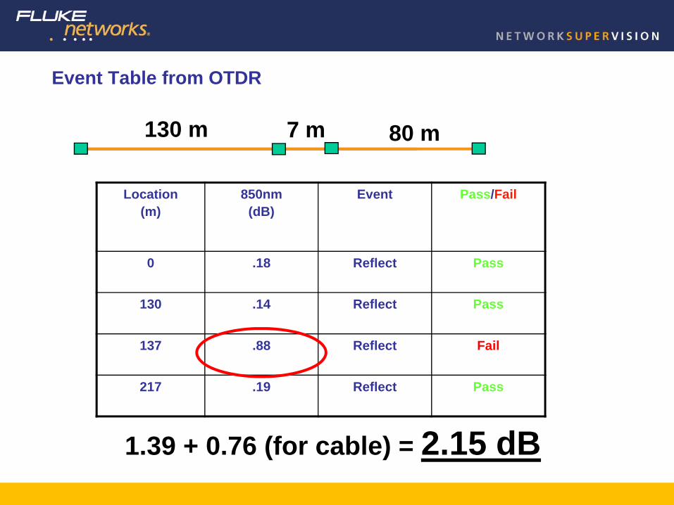
Event Table from OTDR
Location(m)
850nm(dB)
Event Pass/Fail
0 .18 Reflect Pass
130 .14 Reflect Pass
137 .88 Reflect Fail
217 .19 Reflect Pass
1.39 + 0.76 (for cable) = 2.15 dB
130 m 7 m 80 m

19
Endface Inspection and SAVE
ChannelMap
OTDR Trace & Analysis Loss/Length
Certification Records Management & Documentation
Assuring Optical Fiber cabling Performance with Tier II testing

20
Wireless LAN -What is the objective?
• Desired applications drive specifications– “Normal” client use (How might it change?)– VoWLAN– Specialized applications (healthcare patient telemetry, etc.)
• Clear specifications must be agreed upon – Desired data rate– AP coverage/count - % of facility, # of Users – Plan for growth!– Signal strength– Signal to Noise Ratio
Design and Test for Coverage
Design and Testfor Performance
Vs.

21
Network Test Strategies

22
Network Turn-up – Connectivity from TO & Link Utilization
• The switch port performs the basic auto-negotaition function• No DHCP server has been found. No static address has been entered
• Checking the Traffic on this port we learn that the switch port is not “active”
• Can be due to a defective switch port, or a mis-configured port or a disabled port
23
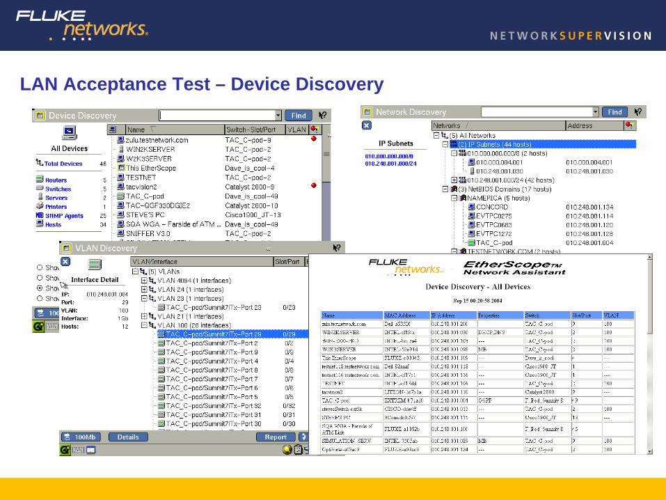
LAN Acceptance Test – Device Discovery

24
LAN Acceptance Test - RFC 2544 testing
• IETF RFC 2544 “discusses and defines a number of tests that may be used to describe the performance characteristics of a network interconnecting device.”
• The RFC 2544 guidelines provide a standard testing methodology• RFC 2544 is optimized for testing single routing devices in a laboratory
environment• Not all the tests are applicable for providers installing or troubleshooting
Ethernet-based IP on active WAN links• 3 of the 6 tests specified by RFC 2544 are really necessary to characterize
performance in an Internet environment– Throughput– Latency– Frame Loss Rate

25
LAN Acceptance Test - RFC 2544
Main Tester
Tester R2
Tester R1

26
Systems Test Strategies

27
System Availability Vs. System Performance?
• Network– Network Availability
• Ex: Network interfaces should be available 99.9999% of the time.– Network Performance
• Ex: Latency on the Houston to Singapore interface should be less than 300 ms.
• Application– Application Availability
• Ex: Oracle application should be available 98% of business hours.– Application Performance
• Ex: 90% of Oracle users should have response time less than 2 seconds.• Which one more accurately reflects user problems?

28
WAN Traffic Analysis - Top N Applications, Talkers, Destinations …

29
Adopting Enterprise Network StrategiesCan be a WIN-WIN situation for DCI / SI &
Customers communities
Thank you.