ergonomic principles and posture assessment or behind the head; twisting at the waist; bending the...
TRANSCRIPT

Ergonomic Principles and Posture Assessment
GLOSSARY
Awkward posture. Deviation from the natural or ―neutral‖ position of a body part. A neutral position places minimal stress on the body part. Awkward postures typically include reaching overhead or behind the head; twisting at the waist; bending the torso forward, backward, or to the side; squatting; kneeling; and bending the wrist.
Cumulative injury (overuse injury). Cumulative injuries develop from repeated loading of body tissues over time. Such injuries include overuse sprains/strains, herniated discs, tendonitis, and carpal tunnel syndrome.
Disorder. A medical condition that occurs when a body part fails to function properly.
Ergonomics. The science of fitting workplace conditions and job demands to the capabilities of workers, and designing and arranging items in the workplace for efficiency and safety.
Fatigue failure. The weakening or breakdown of material subjected to stress, especially a repeated series of stresses.
Force. The amount of physical effort a person uses to perform a task.
Inline grip. A hand tool with a straight handle that is parallel with the direction of the applied energy.
Moment (torque). The tendency to produce motion about an axis.
Moment arm. The perpendicular distance between an applied force and the axis of rotation. For muscles, this is the perpendicular distance between the line of action of the muscle and the center of rotation at the joint.
Musculoskeletal disorders (MSDs). Illnesses and injuries that affect one or more parts of the soft tissue and bones in the body. The parts of the musculoskeletal system are bones, muscles, tendons, ligaments, cartilage, and their associated nerves and blood vessels.
Neutral body posture. The resting position of body parts.
Pinch grip. A grasp in which one presses the thumb against the fingers of the hand and does not involve the palm.
Pistol grip. A tool handle that resembles the handle of a pistol and is typically used when the tool axis must be elevated and horizontal or below waist height and vertical.
Power grip. A grasp where the hand wraps completely around a handle, with the handle running parallel to the knuckles and protruding on either side.
vi

Repetitive. Performing the same motions repeatedly over time. The severity of risk depends on the frequency of repetition, speed of the movement, number of muscle groups involved, and required force.
Risk factor. An action and/or condition that may cause an injury or illness, or make an existing injury or illness worse. Examples related to ergonomics include forceful exertion, awkward posture, and repetitive motion.
Stress. Demand (or ―burden‖) on the human body caused by something outside of the body, such as a work task, the physical environment, work-rest schedules, and social relationships.
Traumatic injury. Injuries that are acute, that may result from instantaneous events such as being struck by objects and that often require immediate medical attention. These types of injuries are often sustained through accidents.
vii

SECTION 1: INTRODUCTION
Musculoskeletal disorders (MSDs) often involve the back, wrist, elbow, and/or shoulder, and occur when workers are exposed over time to MSD risk factors, such as awkward postures, forceful exertions, or repetitive motions. These exposures sometimes occur due to poorly designed workstations, tasks, and/or hand tools [Chaffin et al. 2006; Sanders and McCormick 1993; Silverstein et al. 1996, 1997]. Workers must understand the nature of MSD risk factors and how to avoid exposure to them. In a classroom setting, trainers may discuss ergonomic principles and show examples of MSD risk factors with photographs or videos. However, supplementing training with practical, hands-on demonstrations may further reinforce these ergonomic principles and help workers understand the importance of avoiding exposure to MSD risk factors. Moreover, demonstrations that allow for worker participation result in a greater understanding of the impact exposures to particular MSD risk factors have on workers’ bodies.
This document consists of a series of demonstrations designed to complement training on ergonomic principles. A description of the materials needed and step-by-step methodology are included in this document. Each demonstration highlights worker participation and uses relatively inexpensive materials.
The demonstrations are organized by type of ergonomic principle. Five general topics are addressed:
Neutral compared with non-neutral postures Grip types Hand-tool selection and use Fatigue failure and back pain Moment arms and lifting
The demonstrations show the effects of posture, work methods, workstation design, tools, tasks, and location of materials on worker exposure to MSD risk factors. Many of the demonstrations are appropriate supplements to the NIOSH-developed training ―Ergonomics and Risk Factor Awareness Training for Miners,‖ which is provided to mining employees and
downloadable from the NIOSH mining website: http://www.cdc.gov/niosh/mining/pubs/pubreference/outputid2748.htm [NIOSH 2008] .
Target Users and Audiences
This document was developed for individuals who intend to provide training on ergonomic principles that focus on MSD risk-factor exposures. It was designed for trainers of all experience levels including the beginning trainer. The demonstrations are designed to be performed by both the trainer and the worker. Each demonstration reinforces specific ergonomic principles and teaches the worker how and why to avoid MSD risk factors. Additionally, individuals involved in the purchase and selection of new and/or replacement tools may benefit from many of the demonstrations because they highlight the importance of considering ergonomic principles before purchasing tools.

Format of Demonstration Descriptions
Each section of this document begins with a discussion of an ergonomic principle and its role in avoiding MSD risk factors, followed by a series of demonstrations that may be used to show how the principle can be incorporated into the work environment. Each demonstration starts with clear objective statements and concludes with take-home messages that participants should incorporate into their everyday thinking. These demonstrations encourage audience participation because discussing how the principle plays a role in a worker’s specific workplace is important for promoting understanding. Each demonstration includes the following information:
Objectives of the demonstration List of suggested supplies needed to conduct the demonstration Step-by-step demonstration methodology Take-home messages that should be emphasized during the demonstration
To assist the trainer in knowing how to use some of the suggested supplies (e.g., portable EMG device, hand dynamometer), a series of brief video clips on DVD are included with this document. The DVD also contains video clips that show how to perform the demonstration and the results you should receive when using the portable electromyography (EMG) device.
Suggested Supplies
A complete list of required supplies for performing the demonstrations is provided in Appendix A. As previously mentioned, each demonstration description includes a list of supplies specific to that demonstration. Most of the supplies are available at hardware stores for a reasonable cost.
A portable EMG device is recommended for use with several of the demonstrations (Please see Appendix A for more information regarding the purchase of this device including cost and potential manufacturers). An EMG device is a rudimentary instrument that can be used to make relative comparisons of muscle activity by measuring the electrical activity of a muscle. The muscle emits an electrical signal when it undergoes one of two types of contractions— concentric (i.e., when the muscle shortens as it contracts) or eccentric (i.e., when the muscle lengthens as it contracts). When a contraction of the muscle is detected, the device emits an audible signal of beeps; the frequency of these beeps increases as the measured activity of the muscles beneath the electrodes increases. For example, if you place the electrodes on the inside of the forearm and ask the participant to contract the forearm muscles to 50% of their maximal effort, you will hear the device beep at a specific frequency. If you then ask the participant to contract his or her forearms to a maximal level, the frequency of the beeps will increase.
One problem with measuring muscle activity using electrodes placed on the skin is that the electrodes may measure what is referred to as ―crosstalk.‖ Crosstalk is produced when an electrode measures a signal over a nonactive or nearby muscle. For example, if you apply the electrodes to the inside of the forearm of the participant and have the participant flex his or her wrist (i.e., move the palm towards the inside of the forearm), the forearm muscles being measured are contracting and the EMG device will emit the audible signal. However, if you have the participant extend his or her wrist (i.e., move the palm as far away from the inside of the forearm as they can), the EMG device will still emit an audible signal even though the
2

muscles the electrodes reside above are not contracting. This is an example of crosstalk where the electrodes are detecting activity from the muscles on the other side of the forearm. The electrodes could also be detecting a small eccentric contraction if the participant is using the inner forearm muscles to control the rate at which the wrist is extended. If the trainer is not aware of these issues, the trainer and the participants may be confused by the seemingly mistaken readings. The trainer should practice the demonstrations provided in this document prior to attempting them in front of an audience to minimize any occurrences where this ―crosstalk‖ could cause confusion for the audience members.
Another limitation in using electrodes is that the amount of electrical activity produced by the different muscles of the body varies. Therefore, the EMG device provides the user with the ability to select from several different scales. You may need to adjust the scale in order for the device to be sensitive enough to detect changes in muscle activity for your muscles of interest. You must use the same scale the entire time you are measuring the electrical activity of a specific muscle group; otherwise, you will not be able to make a direct comparison to the muscle activity before and after an event.
Graphics
Appendix B includes several images that may be useful to show in a PowerPoint presentation when conducting the demonstrations. Electronic files for these graphics are found on the DVD provided with this document.
3

SECTION 2: NEUTRAL POSTURES
Principles
Use neutral postures:
o Maximum muscle force producible in neutral postures is greater than maximum muscle force producible in awkward postures.
o Fatigue occurs sooner when working in awkward postures.
o Working in extreme awkward postures (near extreme ranges of motion) causes stress on muscles and joints.
A neutral posture is achieved when the muscles are at their resting length and the joint is naturally aligned. For most joints, the neutral posture is associated with the midrange of motion for that joint. When a joint is not in its neutral posture, its muscles and tendons are either contracted or elongated. Joints in neutral postures have maximum control and force production [Basmajian and De Luca 1985; Chaffin et al. 2006]. Neutral postures also minimize the stress applied to muscles, tendons, nerves, and bones. A posture is considered ―awkward‖ when it
moves away from the neutral posture toward the extremes in range of motion.
For the most part, a worker is capable of producing his or her highest amount of force when a joint is in its neutral posture. As the joint moves away from the neutral posture, the amount of force the muscles can produce decreases because some of the muscle fibers are either contracted or elongated [Clarke 1966; Kumar 2004]. Also, when you bend your wrist, the tendons of the muscles partially wrap around the carpal bones in the wrist. Because the bones do not act as a perfect pulley, a loss in the force that can be produced will occur. Furthermore, losses in force are also experienced due to friction [Ozkaya and Nordin 1999]. Thus, in order for a worker to produce the same force in an awkward posture as they do in the neutral posture, the worker’s muscles must work harder and expend more energy. Working in an awkward posture, therefore, is a MSD risk factor that should be avoided. This is an extremely important principle because working closer to one’s maximum capability, especially without rest, may result in an earlier onset of fatigue and, over time, may also increase the risk of MSDs [Chaffin et al. 2006]. Ideally, tasks and workspaces should be designed so that work is conducted at approximately 15% or less of maximum capacity [Chaffin et al. 2006].
Therefore, to minimize the level of effort as a percentage of the maximum capacity, you should help workers use the neutral posture of their joints. However, some joint motion must occur because remaining in a static posture for too long produces several negative consequences and should be avoided. When a worker remains in a static posture, the prolonged application of a load by the muscles can result in fatigue. Also, not moving muscles for a time impedes blood
4
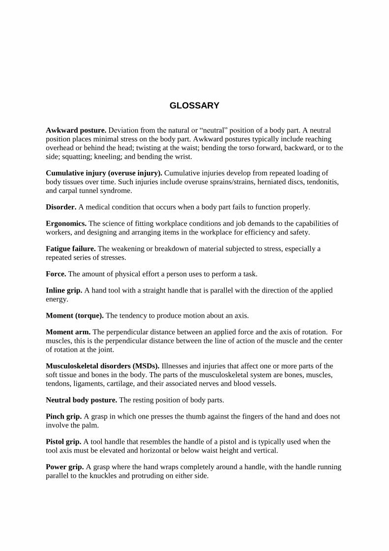
flow, which is needed to bring oxygen and crucial nutrients to the muscles and to remove metabolic waste products. Static postures are avoided when work is dynamic, with the muscles and joints periodically moving. With this in mind, workstations, tasks, and hand tools should be designed to enable workers to use primarily neutral postures and postures that are in relative proximity to the neutral posture. Care should be taken to ensure that awkward postures are not frequent and that high forces are not required while in awkward postures. Figures 1–4 show neutral and awkward postures for the joints (e.g., wrist, elbow, shoulder, and back).
Figure 1. Neutral and awkward wrist postures.
These topics will be discussed in more detail in this document.
Special considerations are made for the back and hand. Even though the neutral posture of the back technically occurs with the back slightly forward flexed, lifting in a flexed posture can place unwanted forces on the spine itself. Lifting tasks should be performed while the back is not flexed, and the nonflexed posture is often called the neutral posture of the back. The neutral posture for the hand is achieved when the fingers are in a slightly flexed (relaxed) position [Bechtol 1954].
5
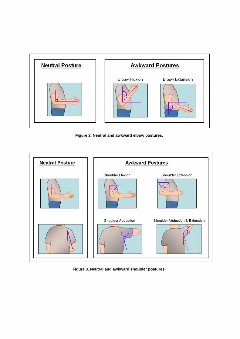
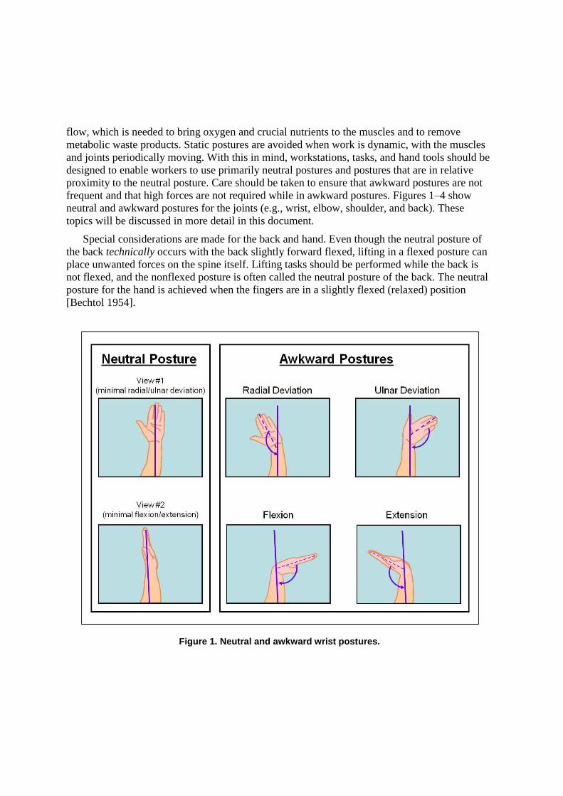
Figure 2. Neutral and awkward elbow postures.
Figure 3. Neutral and awkward shoulder postures.
6
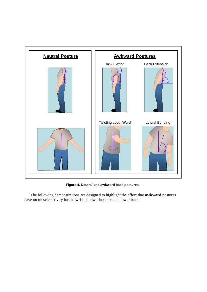
Figure 4. Neutral and awkward back postures.
The following demonstrations are designed to highlight the effect that awkward postures have on muscle activity for the wrist, elbow, shoulder, and lower back.
7
Effects of Postures on Muscle Activity
Objectives
To understand the effect of neutral and awkward postures on muscle activity for the wrist, elbow, shoulder, and lower back
Supplies
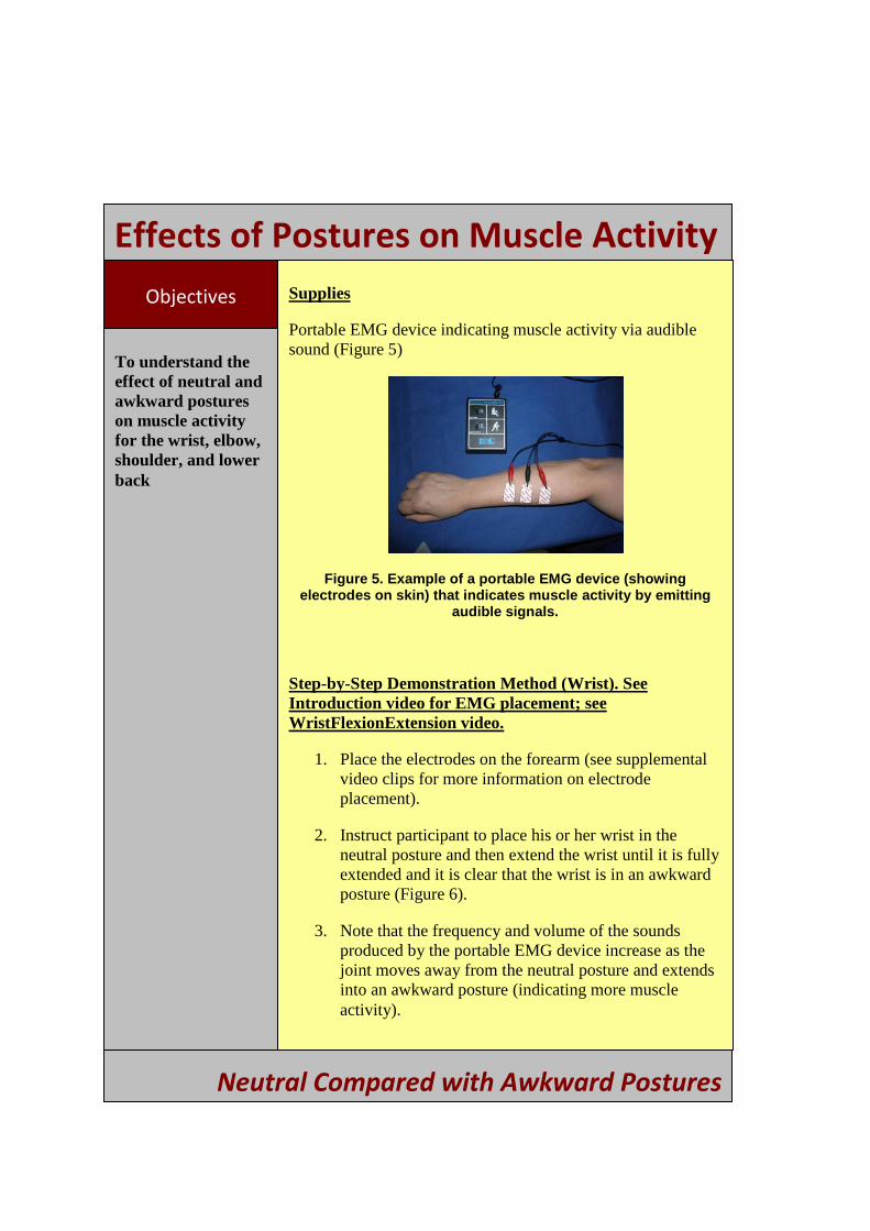
Portable EMG device indicating muscle activity via audible sound (Figure 5)
Figure 5. Example of a portable EMG device (showing electrodes on skin) that indicates muscle activity by emitting
audible signals.
Step-by-Step Demonstration Method (Wrist). See Introduction video for EMG placement; see WristFlexionExtension video.
1. Place the electrodes on the forearm (see supplemental video clips for more information on electrode placement).
2. Instruct participant to place his or her wrist in the neutral posture and then extend the wrist until it is fully extended and it is clear that the wrist is in an awkward posture (Figure 6).
3. Note that the frequency and volume of the sounds produced by the portable EMG device increase as the joint moves away from the neutral posture and extends into an awkward posture (indicating more muscle activity).
Neutral Compared with Awkward Postures
8

4.
5.
Effects of Postures on Muscle Activity
Ask the audience to identify tasks at their worksite where they use extended wrist postures or other awkward postures of the wrist (excessive flexion, extension, and radial/ulnar deviations).
Discuss with the audience whether it would be possible to use a neutral posture to perform these tasks. If not, ask the audience why they are limited to awkward postures. Identify changes to workstation design, tasks, tools, or location of materials that may allow neutral postures to be used.
Figure 6. Wrist postures and electrode placement for portable EMG device.
Neutral Compared with Awkward Postures
9
Effects of Postures on Muscle Activity
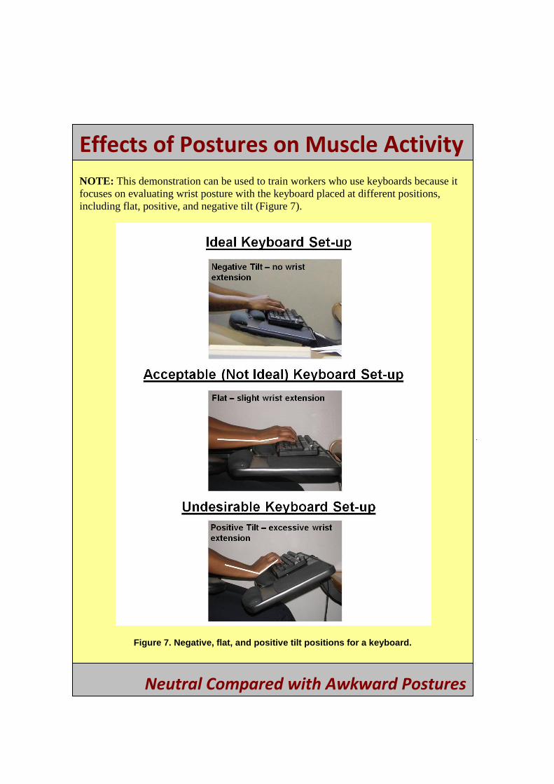
NOTE: This demonstration can be used to train workers who use keyboards because it focuses on evaluating wrist posture with the keyboard placed at different positions, including flat, positive, and negative tilt (Figure 7).
Figure 7. Negative, flat, and positive tilt positions for a keyboard.
Neutral Compared with Awkward Postures
10
Effects of Postures on Muscle Activity
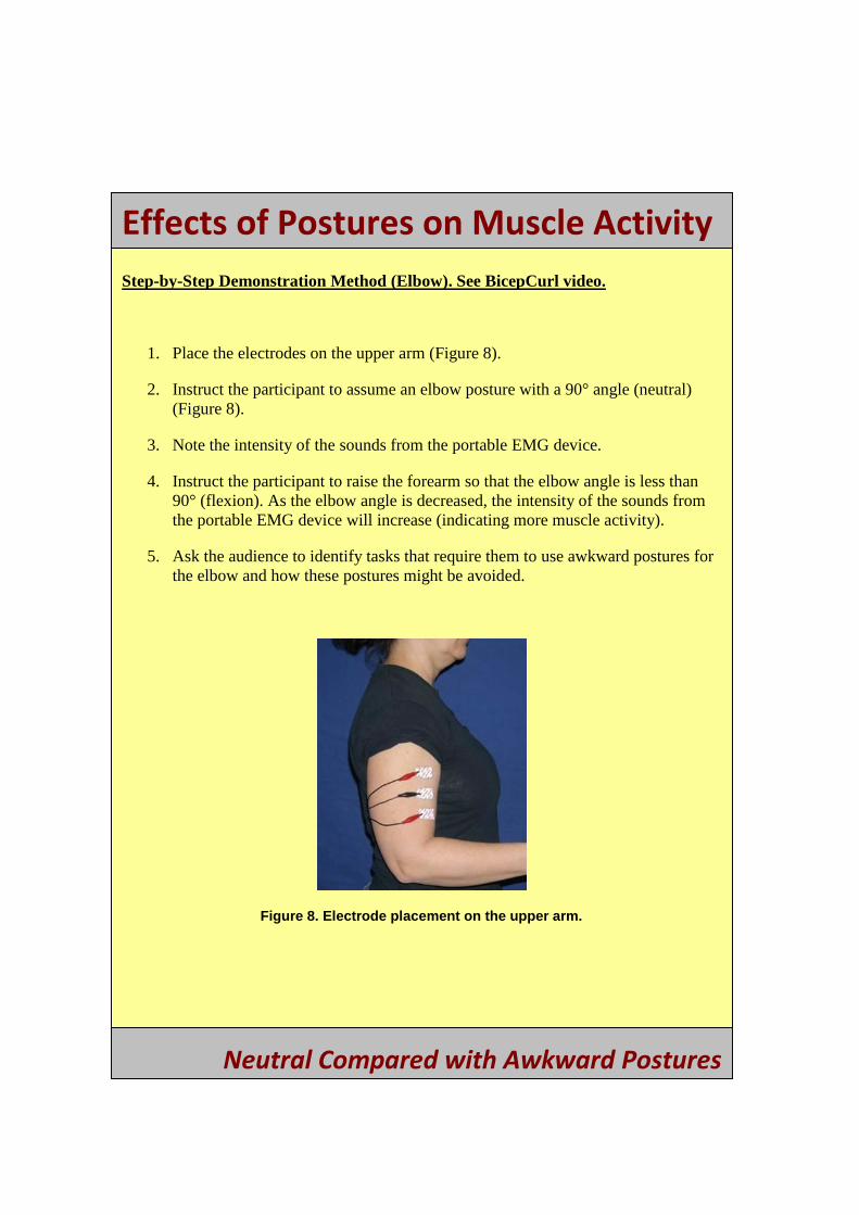
Step-by-Step Demonstration Method (Elbow). See BicepCurl video.
1. Place the electrodes on the upper arm (Figure 8).
2. Instruct the participant to assume an elbow posture with a 90° angle (neutral) (Figure 8).
3. Note the intensity of the sounds from the portable EMG device.
4. Instruct the participant to raise the forearm so that the elbow angle is less than 90° (flexion). As the elbow angle is decreased, the intensity of the sounds from the portable EMG device will increase (indicating more muscle activity).
5. Ask the audience to identify tasks that require them to use awkward postures for the elbow and how these postures might be avoided.
Figure 8. Electrode placement on the upper arm.
Neutral Compared with Awkward Postures
11
Effects of Postures on Muscle Activity
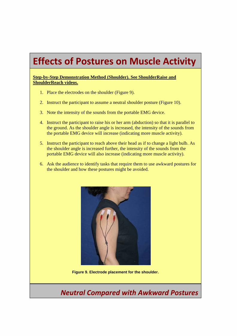
Step-by-Step Demonstration Method (Shoulder). See ShoulderRaise and ShoulderReach videos.
1. Place the electrodes on the shoulder (Figure 9).
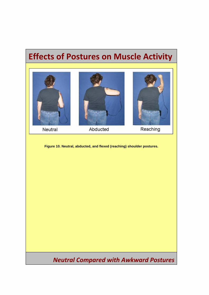
2. Instruct the participant to assume a neutral shoulder posture (Figure 10).
3. Note the intensity of the sounds from the portable EMG device.
4. Instruct the participant to raise his or her arm (abduction) so that it is parallel to the ground. As the shoulder angle is increased, the intensity of the sounds from the portable EMG device will increase (indicating more muscle activity).
5. Instruct the participant to reach above their head as if to change a light bulb. As the shoulder angle is increased further, the intensity of the sounds from the portable EMG device will also increase (indicating more muscle activity).
6. Ask the audience to identify tasks that require them to use awkward postures for the shoulder and how these postures might be avoided.
Figure 9. Electrode placement for the shoulder.
Neutral Compared with Awkward Postures
12
Effects of Postures on Muscle Activity
Figure 10. Neutral, abducted, and flexed (reaching) shoulder postures.
Neutral Compared with Awkward Postures
13

Effects of Postures on Muscle Activity Step-by-Step Demonstration Method (Low Back). See BackFlexionNoWeight video.
1. Place the electrodes on the low back. (Figure 11).
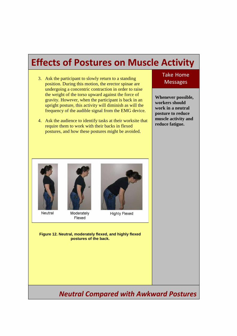
2. Instruct the participant to slowly lean forward with the back at about a 45°–60° angle, and note the increase in the intensity of the sounds from the portable EMG device (Figure 12). The muscle group being tested is referred to as the erector spinae, which undergoes an eccentric contraction as the trunk flexes forward. The erector spinae helps control the rate at which the torso is lowered by acting against the abdominal muscles that are performing a concentric contraction to flex the trunk. However, make sure the participant does not flex until their torso is fully horizontal since the erector spinae is not as active once the torso comes to rest. The decreased activity, as indicated by a decrease in audible EMG signals, may be confusing to the audience. Before performing this demonstration in front of a group, practice determining the position of the torso when the activity of the erector spinae diminishes. This will help you to advise the participant to avoid going beyond this position. Although muscle activity has decreased at postures near full flexion, the spine continues to be loaded in an undesirable manner.
Figure 11. Electrode placement for the back (line indicates location of spine). It is important that the electrodes are placed on the muscles as shown in the photograph. If
the electrodes are placed too high on the back, the demonstration will not work properly.
Neutral Compared with Awkward Postures
14
Effects of Postures on Muscle Activity Take -Home Messages
Whenever possible, workers should work in a neutral posture to reduce muscle activity and reduce fatigue.
3. Ask the participant to slowly return to a standing position. During this motion, the erector spinae are undergoing a concentric contraction in order to raise the weight of the torso upward against the force of gravity. However, when the participant is back in an upright posture, this activity will diminish as will the frequency of the audible signal from the EMG device.
4. Ask the audience to identify tasks at their worksite that require them to work with their backs in flexed postures, and how these postures might be avoided.
Figure 12. Neutral, moderately flexed, and highly flexed postures of the back.
Neutral Compared with Awkward Postures
15
Wrist Angle and Grip Strength
Objectives
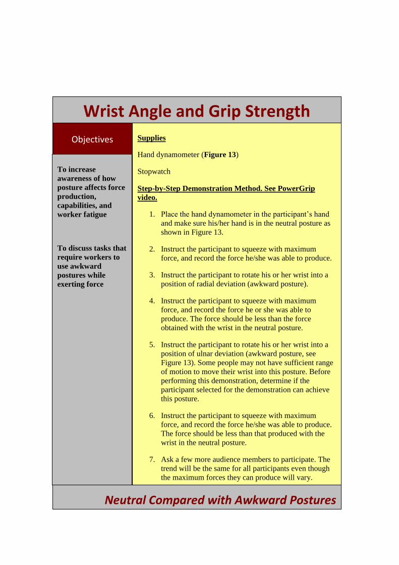
To increase awareness of how posture affects force production, capabilities, and worker fatigue
To discuss tasks that require workers to use awkward postures while exerting force
Supplies
Hand dynamometer (Figure 13)
Stopwatch
Step-by-Step Demonstration Method. See PowerGrip video.
1. Place the hand dynamometer in the participant’s hand and make sure his/her hand is in the neutral posture as shown in Figure 13.
2. Instruct the participant to squeeze with maximum force, and record the force he/she was able to produce.
3. Instruct the participant to rotate his or her wrist into a position of radial deviation (awkward posture).
4. Instruct the participant to squeeze with maximum force, and record the force he or she was able to produce. The force should be less than the force obtained with the wrist in the neutral posture.
5. Instruct the participant to rotate his or her wrist into a position of ulnar deviation (awkward posture, see Figure 13). Some people may not have sufficient range of motion to move their wrist into this posture. Before performing this demonstration, determine if the participant selected for the demonstration can achieve this posture.
6. Instruct the participant to squeeze with maximum force, and record the force he/she was able to produce. The force should be less than that produced with the wrist in the neutral posture.
7. Ask a few more audience members to participate. The trend will be the same for all participants even though the maximum forces they can produce will vary.
Neutral Compared with Awkward Postures
16
Wrist Angle and Grip Strength
8. Now ask each participant to exert a force of 20 lbs while in the neutral posture, and hold that force as long as possible. Record the length of time the participant maintains the posture. Then, ask the participants to do the same using wr ist positions with radial and ulnar deviations; because fatigue occurs sooner in these postures, the length of time the force can be maintained for these postures should be less than the time the force can be maintained using a neutral posture.
9. Ask the audience to identify tasks at their worksite where awkward postures of the wrist occur.
NOTE: Dramatic results will also be seen if this demonstration is performed with the wrist in extension or flexion as shown in Figure 1.
Neutral Compared with Awkward Postures
17

Wrist Angle and Grip Strength Take -Home Messages
When body joints are in awkward postures, maximum force produced decreases.
Muscle fatigue will occur earlier when working in an awkward posture instead of a neutral posture.
Figure 13. Hand dynamometer showing how wrist angle affects force production for neutral, ulnar deviation, and radial
deviation wrist postures.
Neutral Compared with Awkward Postures
18
GSECTION 3: GRIP TYPES
Principles
Force generated with a pinch grip is about 15%–25% of force generated with a power grip.
Use a power grip when higher forces are required.
Use a pinch grip when precise movements are needed, and the force required is low (< 2 lbs).
Research shows the design width of power grips should be 1.75 to 3.75 inches.
In general, an object can be grasped using one of two methods: a pinch grip or a power grip (Figure 14). A power grip curls the fingers toward the palm; a pinch grip presses the thumb against the fingers of the hand or an object, and does not involve the palm. The amount of force that can be generated depends on the type of grip and the width of the grip.
Three types of pinch grips can be used:
Tip pinch—using only the tips of the fingers and thumb (holding a bead)
Chuck pinch—using the thumb and first two fingers (holding a pencil)
Lateral pinch—using the thumb and side of the first finger (holding a key)
For a given force, using a pinch grip is biomechanically more stressful than using a power grip. The amount of force one is capable of exerting is greater for the power grip than for the pinch grip. A general rule of thumb is that the force generated with a pinch grip is about 15%– 25% of the force generated with a power grip, depending on the type of pinch grip and the worker’s individual force capability. The amount of force exerted also varies among the three
types of pinch grips. When using a tip pinch, the force exerted is 71%–72% of the lateral pinch force; when using a chuck pinch, the force exerted is 98% of the lateral pinch force. The amount of force generated by power grips and pinch grips also varies depending on the width of the grip. For a power grip, the maximum force is generated with a grip width of 1.75–3.75 inches. For a pinch grip (type not specified by citation), the maximum force is generated with a grip width of 1–3 inches [Chengalur et al. 2004].
19
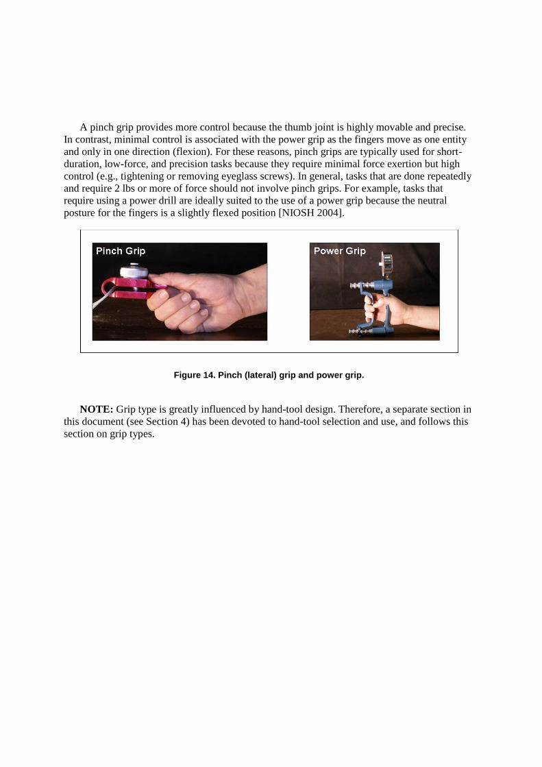
A pinch grip provides more control because the thumb joint is highly movable and precise. In contrast, minimal control is associated with the power grip as the fingers move as one entity and only in one direction (flexion). For these reasons, pinch grips are typically used for short-duration, low-force, and precision tasks because they require minimal force exertion but high control (e.g., tightening or removing eyeglass screws). In general, tasks that are done repeatedly and require 2 lbs or more of force should not involve pinch grips. For example, tasks that require using a power drill are ideally suited to the use of a power grip because the neutral posture for the fingers is a slightly flexed position [NIOSH 2004].
Figure 14. Pinch (lateral) grip and power grip.
NOTE: Grip type is greatly influenced by hand-tool design. Therefore, a separate section in this document (see Section 4) has been devoted to hand-tool selection and use, and follows this section on grip types.
20
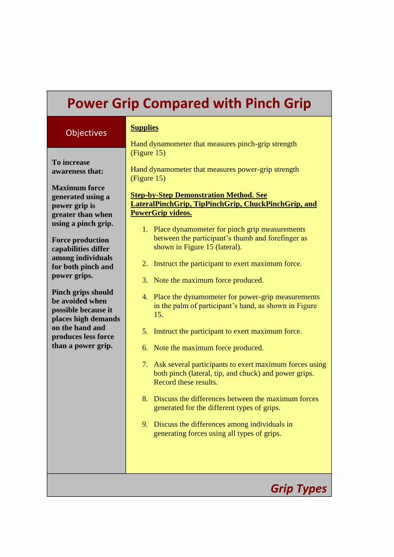
Power Grip Compared with Pinch Grip
Objectives
To increase awareness that:
Maximum force generated using a power grip is greater than when using a pinch grip.
Force production capabilities differ among individuals for both pinch and power grips.
Pinch grips should be avoided when possible because it places high demands on the hand and produces less force than a power grip.
Supplies
Hand dynamometer that measures pinch-grip strength (Figure 15)
Hand dynamometer that measures power-grip strength (Figure 15)
Step-by-Step Demonstration Method. See LateralPinchGrip, TipPinchGrip, ChuckPinchGrip, and PowerGrip videos.
1. Place dynamometer for pinch grip measurements between the participant’s thumb and forefinger as shown in Figure 15 (lateral).
2. Instruct the participant to exert maximum force.
3. Note the maximum force produced.
4. Place the dynamometer for power-grip measurements in the palm of participant’s hand, as shown in Figure
15.
5. Instruct the participant to exert maximum force.
6. Note the maximum force produced.
7. Ask several participants to exert maximum forces using both pinch (lateral, tip, and chuck) and power grips. Record these results.
8. Discuss the differences between the maximum forces generated for the different types of grips.
9. Discuss the differences among individuals in generating forces using all types of grips.
Grip Types
21

Power Grip Compared with Pinch Grip
Take -Home Messages
A pinch grip should be used only for precision tasks that require minimal forces to be generated.
In general, pinch grips should be avoided for any length of time, regardless of the force required.
A power grip should be used for tasks that require larger forces, that do not require high degrees of precision and dexterity.
10. Discuss specific tasks that would be appropriate for using either type of grip.
11. Identify specific tasks the worker performs that uses the different types of grips, and determine if the grip is appropriate for the task requirements.
Figure 15. Example of the maximum forces generated for a pinch grip (lateral) and a power grip.
Grip Types
22
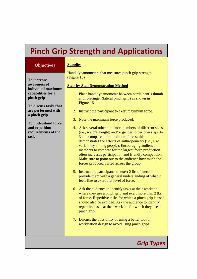
Pinch Grip Strength and Applications
Objectives
To increase awareness of individual maximum capabilities for a pinch grip
To discuss tasks that are performed with a pinch grip
To understand force and repetition requirements of the task
Supplies
Hand dynamometers that measures pinch grip strength (Figure 16)
Step-by-Step Demonstration Method
1. Place hand dynamometer between participant’s thumb and forefinger (lateral pinch grip) as shown in Figure 16.
2. Instruct the participant to exert maximum force.
3. Note the maximum force produced.
4. Ask several other audience members of different sizes (i.e., weight, height) and/or gender to perform steps 1– 3 and compare their maximum forces; this demonstrates the effects of anthropometry (i.e., size variability among people). Encouraging audience members to compete for the largest force production often increases participation and friendly competition. Make sure to point out to the audience how much the forces produced varied across the group.
5. Instruct the participants to exert 2 lbs of force to provide them with a general understanding of what it feels like to exert that level of force.
6. Ask the audience to identify tasks at their worksite where they use a pinch grip and exert more than 2 lbs of force. Repetitive tasks for which a pinch grip is used should also be avoided. Ask the audience to identify repetitive tasks at their worksite for which they use a pinch grip.
7. Discuss the possibility of using a better tool or workstation design to avoid using pinch grips.
Grip Types
23

Pinch Grip Strength and Applications Take -Home Messages
Maximum forces exerted with a pinch grip vary among workers.
A pinch grip should not be used when high forces or repetition are required.
Pinch grips should be used only for tasks that require small forces (< 2 lbs).
Figure 16. Example of a pinch grip (lateral) and the resulting maximum force.
Grip Types
24
Power Grip: Effect of Grip Width
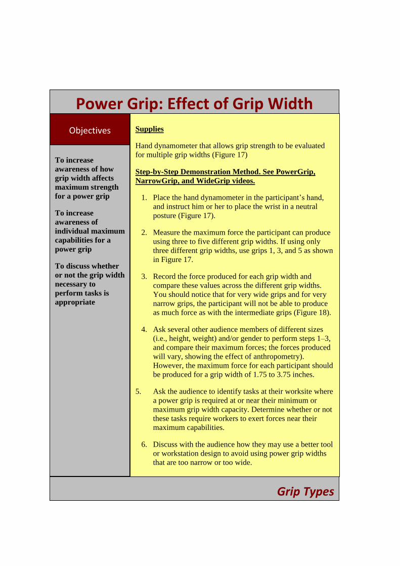
Objectives
To increase awareness of how grip width affects maximum strength for a power grip
To increase awareness of individual maximum capabilities for a power grip
To discuss whether or not the grip width necessary to perform tasks is appropriate
Supplies
Hand dynamometer that allows grip strength to be evaluated for multiple grip widths (Figure 17)
Step-by-Step Demonstration Method. See PowerGrip, NarrowGrip, and WideGrip videos.
1. Place the hand dynamometer in the participant’s hand, and instruct him or her to place the wrist in a neutral posture (Figure 17).
2. Measure the maximum force the participant can produce using three to five different grip widths. If using only three different grip widths, use grips 1, 3, and 5 as shown in Figure 17.
3. Record the force produced for each grip width and compare these values across the different grip widths. You should notice that for very wide grips and for very narrow grips, the participant will not be able to produce as much force as with the intermediate grips (Figure 18).
4. Ask several other audience members of different sizes (i.e., height, weight) and/or gender to perform steps 1–3, and compare their maximum forces; the forces produced will vary, showing the effect of anthropometry). However, the maximum force for each participant should be produced for a grip width of 1.75 to 3.75 inches.
5. Ask the audience to identify tasks at their worksite where a power grip is required at or near their minimum or maximum grip width capacity. Determine whether or not these tasks require workers to exert forces near their maximum capabilities.
6. Discuss with the audience how they may use a better tool or workstation design to avoid using power grip widths that are too narrow or too wide.
Grip Types
25
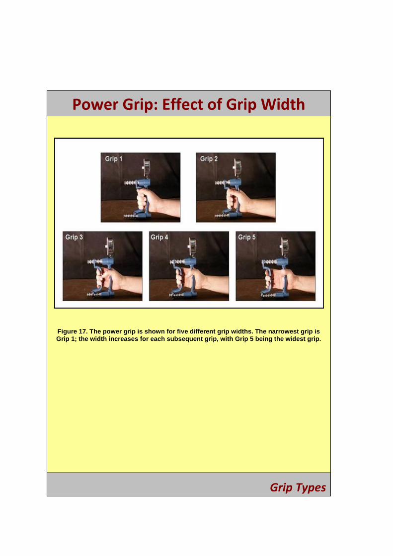
Power Grip: Effect of Grip Width
Figure 17. The power grip is shown for five different grip widths. The narrowest grip is Grip 1; the width increases for each subsequent grip, with Grip 5 being the widest grip.
Grip Types
26
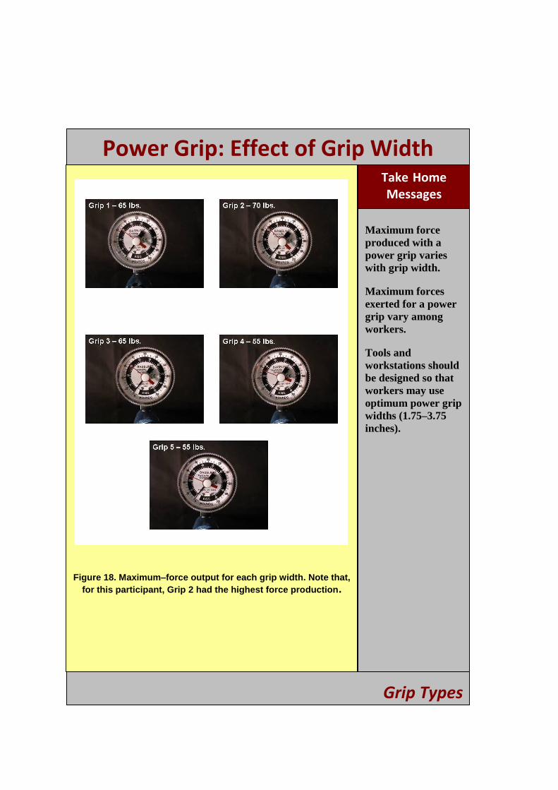
Power Grip: Effect of Grip Width Take -Home Messages
Maximum force produced with a power grip varies with grip width.
Maximum forces exerted for a power grip vary among workers.
Tools and workstations should be designed so that workers may use optimum power grip widths (1.75–3.75 inches).
Figure 18. Maximum–force output for each grip width. Note that, for this participant, Grip 2 had the highest force production.
Grip Types
27
SECTION 4: HAND-TOOL SELECTION AND USE
Principles
Select tools that allow neutral postures to be used.
Use tools with handles designed for a power grip.
Use tools with handles that are appropriately sized and shaped for the user’s hand.
Use tools with built-in features (e.g., springs that open tool handles) that minimize forceful exertions required to use the tool.
When operating heavy tools, ensure they accommodate using both hands to support the tool's weight.
Hand-tool design can play an important role in the reduction of MSDs. A tool that is designed with consideration for the worker’s tasks can greatly reduce the worker’s exposure to
risk factors for MSD. However, using a poorly designed tool or an inappropriate tool negatively impacts the entire body by dictating the postures assumed by the worker to complete the task, and increasing the resulting forces exerted by the worker. Such tools can also directly apply unwanted forces or vibrations to other body parts.
Several factors should be considered when purchasing or selecting a hand tool. The topics discussed in the above sections all play a role in whether or not a hand tool is designed with the worker or task in mind. Some of these points will become clearer after performing the demonstrations in this section. Before performing these demonstrations, consider the following questions related to the safety of the tools you use:
Does the orientation of the handle allow the worker to use neutral joint postures? Does the size of the handle allow for the midrange of grip (1.75–3.75 inche s; hand in the shape of a ―C‖) width when using a power grip?
Does the handle extend past the palm? Is the handle shape contoured to fit the palm? If a pinch grip is required, is the force the worker must exert < 2 lbs.? For heavier tools, such as power tools, do the features of the tool allow the worker to support the tool’s weight with both hands?
To obtain a detailed checklist for hand-tool selection, refer to the NIOSH publication ―Easy Ergonomics: A Guide to Selecting Non-Powered Hand Tools‖ [NIOSH 2004].
28

Tool-Handle Size and Shape
Objectives
To understand why handle size is important when selecting tools
Supplies
One screwdriver, whose handle has a diameter size that complements the hand and a comfortable, appropriate shape
One screwdriver, whose handle has a smaller diameter size that does not complement the hand and does not have a comfortable, appropriate shape
Wood block with screw
Clamp to affix wood block to tabletop
Step-by-Step Demonstration Method
1. Clamp wood block and screw to tabletop.
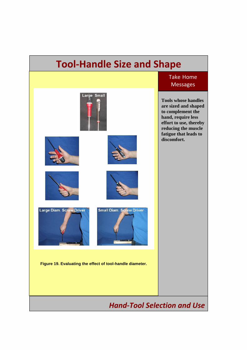
2. Instruct the participant to grasp the appropriately sized screwdriver that has the larger diameter handle. Instruct the participant to show the audience how he/she is gripping the screwdriver (Figure 19).
3. Repeat the previous step using the other screwdriver, with a smaller diameter handle that does not complement the hand. Discuss observed differences in gripping the two screwdrivers.
4. Instruct the participant to drive a screw with both screwdrivers. Ask them which one feels more comfortable in his or her hand and is easier to grasp when the screw starts to provide resistance. The handle with the larger diameter that complements the hand should make it easier for the participant to apply torque to drive the screw.
5. Discuss with the audience the fact that selecting a hand tool with a handle that complements the hand reduces the effort needed to accomplish the task, thus reducing fatigue and the required muscle activity; this, in turn, reduces discomfort while using the tool.
Hand-Tool Selection and Use
29
Tool-Handle Size and Shape Take -Home Messages
Tools whose handles are sized and shaped to complement the hand, require less effort to use, thereby reducing the muscle fatigue that leads to discomfort.
Figure 19. Evaluating the effect of tool-handle diameter.
Hand-Tool Selection and Use
30
Tool-Handle Orientation
Objectives
To demonstrate how tool-handle adjustability or orientation may allow for neutral postures to be adopted
To encourage workers using and purchasing tools to consider how the tool will be applied and whether or not a different tool, or tool configuration, would be more appropriate
Supplies
Screwdriver (battery-powered) with pistol-grip and inline-grip capabilities (Figure 20)
Wood block with screw in block
Clamp to hold wood block in place while screw is being driven with screwdriver
Step-by-Step Demonstration Method
1. Clamp the wood block to a tabletop so that the block is perpendicular to the table and the screw is driven parallel to the tabletop.
2. Place the screwdriver in the inline position, and instruct the participant to begin driving the screw.
3. Place the screwdriver in the pistol-grip position, and instruct the participant to begin driving the screw.
4. Ask the participant if he or she can feel a difference between the two techniques. Ask the audience which grip would be best to use for this task (answer: pistol grip).
5. Clamp the wood block to a tabletop so that the block is parallel to the table and the screw is driven perpendicular to the tabletop.
6. Place the screwdriver in the inline position, and instruct the participant to begin driving the screw.
7. Place the screwdriver in a pistol-grip position, and instruct the participant to begin driving the screw.
8. Ask the participant if he or she feels a difference between the two techniques. Ask the audience which grip would be best to use for this task (answer could vary depending on height of participant relative to the tabletop which affects his/her wrist and shoulder angle).
Hand-Tool Selection and Use
31
Tool-Handle Size and Shape Take -Home Messages
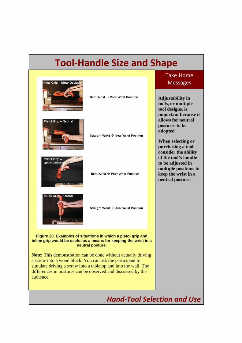
Adjustability in tools, or multiple tool designs, is important because it allows for neutral postures to be adopted
When selecting or purchasing a tool, consider the ability of the tool’s handle
to be adjusted in multiple positions to keep the wrist in a neutral posture.
Figure 20. Examples of situations in which a pistol grip and inline grip would be useful as a means for keeping the wrist in a
neutral posture.
Note: This demonstration can be done without actually driving a screw into a wood block. You can ask the participant to simulate driving a screw into a tabletop and into the wall. The differences in postures can be observed and discussed by the audience.
Hand-Tool Selection and Use
32
Features to Reduce Forceful Exertions
Objectives
To increase awareness that some tools have design features that reduce forceful exertions when the tool is used to perform a task
Supplies
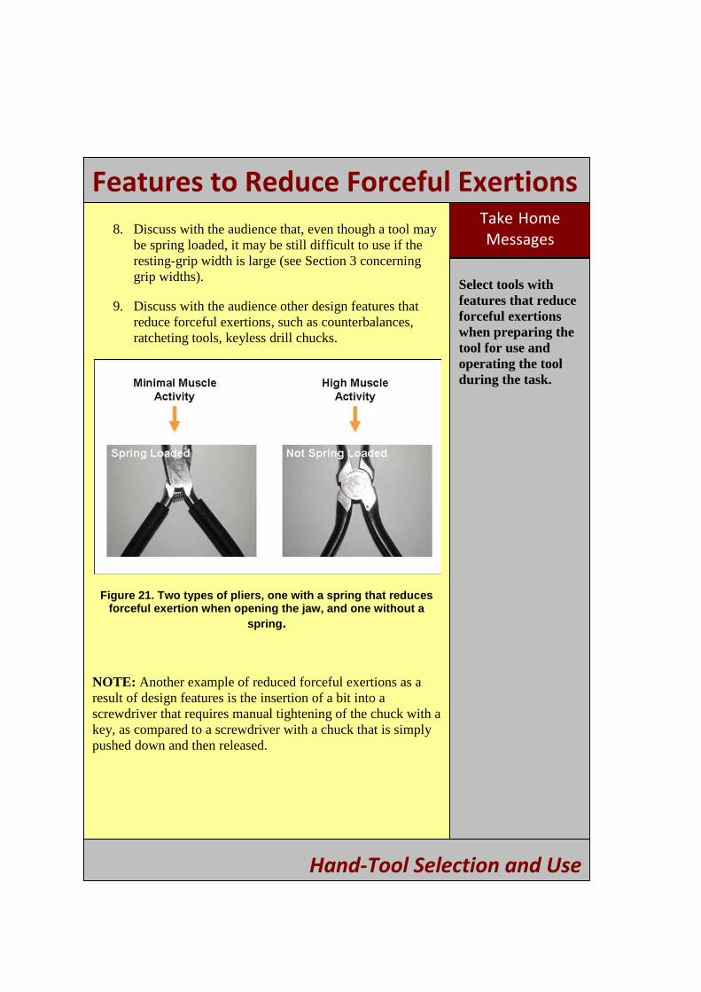
Spring-loaded, needle-nose pliers (Figure 21)
Needle-nose pliers that are not spring loaded (Figure 21)
Portable EMG device with audible sounds to indicate muscle activity (optional) (Figure 5)
Step-by-Step Demonstration Method
1. If using a portable EMG device, place the electrodes on the forearm a s shown in Figure 5.
2. Adjust the output sounds to a range where minimal sounds are heard when the participant wiggles his or her fingers.
3. Instruct the participant to close and then open the spring-loaded, needle-nose pliers.
4. Note the intensity of the sounds from the portable EMG device.
5. Instruct the participant to close and then open the needle-nose pliers that are not spring loaded.
6. The intensity of the sounds from the portable EMG device will be increased when using the nonspring loaded pliers compared to the spring-loaded pliers. When using pliers for a work activity, individuals often use their dominant hand to both open and close the pliers. Spring-loaded pliers remove the need to open the pliers and reduces the force requirements on the hand.
7. Ask the participant if he or she can feel a difference between the two tools.
Hand Tool Selection and Use
33
Features to Reduce Forceful Exertions Take -Home Messages
Select tools with features that reduce forceful exertions when preparing the tool for use and operating the tool during the task.
8. Discuss with the audience that, even though a tool may be spring loaded, it may be still difficult to use if the resting-grip width is large (see Section 3 concerning grip widths).
9. Discuss with the audience other design features that reduce forceful exertions, such as counterbalances, ratcheting tools, keyless drill chucks.
Figure 21. Two types of pliers, one with a spring that reduces forceful exertion when opening the jaw, and one without a
spring.
NOTE: Another example of reduced forceful exertions as a result of design features is the insertion of a bit into a screwdriver that requires manual tightening of the chuck with a key, as compared to a screwdriver with a chuck that is simply pushed down and then released.
Hand-Tool Selection and Use
34

One- and Two-Handed Tools
Objectives
To demonstrate that muscle activity decreases when forces are distributed across both arms instead of just one arm
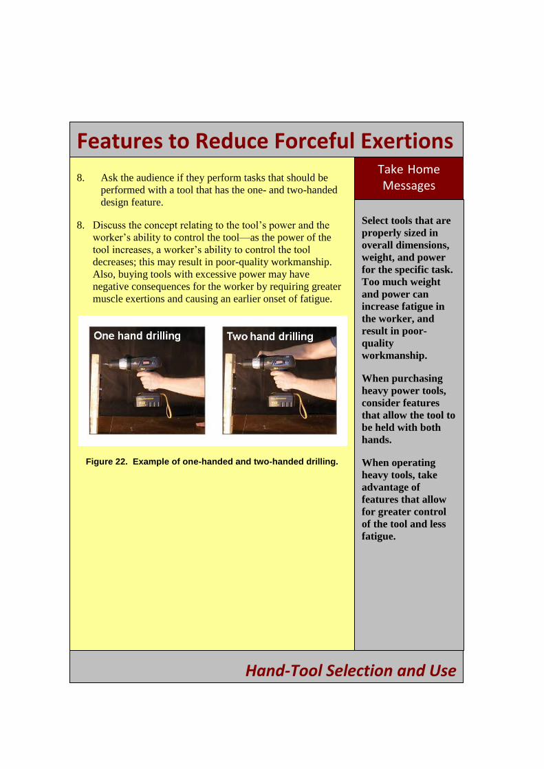
To inform workers that they should purchase and use tools with appropriate power because too much power for the job may result in difficulty controlling the tool, increased fatigue, and poor-quality workmanship
Supplies
Electric drill with capability to hold drill with one hand or with two hands using an additional handle (Figure 22)
Wood block with a screw
Clamp to affix wood block to a table
Step-by-Step Demonstration Method
1. Instruct the participant to hold the drill at waist height and then at shoulder height with one hand, and note the degree of effort required to hold the drill for both.
2. Instruct the participant to grab the additional handle with the second hand, and again hold the drill at waist and then shoulder height. It should be easier with both hands on the tool because the muscles from both arms are now being used to hold the drill; this reduces the force produced by each individual muscle.
3. Explain to the audience that, because force in each muscle has decreased, fatigue will set in later than if the task was performed with only one hand.
4. Clamp down the wood block with the screw.
5. Instruct the participant to drive the screw while holding the drill with only one hand.
6. Instruct the participant to drive the screw while holding the drill with both hands.
7. Ask the participant if he or she feels more control when using two hands.
Hand-Tool Selection and Use
35
Features to Reduce Forceful ExertionsTake -Home Messages
Select tools that are properly sized in overall dimensions, weight, and power for the specific task. Too much weight and power can increase fatigue in the worker, and result in poor- quality workmanship.
When purchasing heavy power tools, consider features that allow the tool to be held with both hands.
When operating heavy tools, take advantage of features that allow for greater control of the tool and less fatigue.
8. Ask the audience if they perform tasks that should be performed with a tool that has the one- and two-handed design feature.
8. Discuss the concept relating to the tool’s power and the worker’s ability to control the tool—as the power of the tool increases, a worker’s ability to control the tool
decreases; this may result in poor-quality workmanship. Also, buying tools with excessive power may have negative consequences for the worker by requiring greater muscle exertions and causing an earlier onset of fatigue.
Figure 22. Example of one-handed and two-handed drilling.
Hand-Tool Selection and Use
36
SECTION 5: FATIGUE FAILURE AND BACK PAIN
Principles
Repeated lifting, even at submaximal levels, may eventually lead to damage of the spine (fatigue failure).
Substantially reducing loads placed on the spine can greatly minimize the risk of fatigue failure.
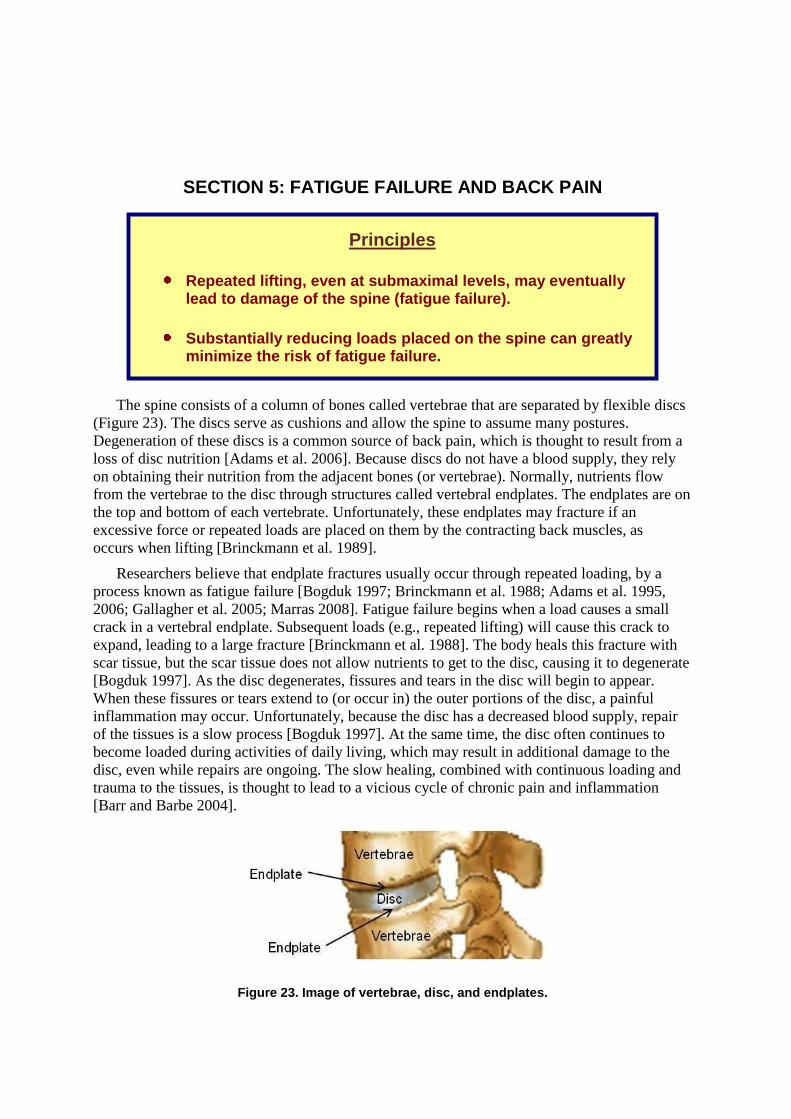
The spine consists of a column of bones called vertebrae that are separated by flexible discs (Figure 23).
Figure 23. Image of vertebrae, disc, and endplates.
The discs serve as cushions and allow the spine to assume many postures. Degeneration of these discs is a common source of back pain, which is thought to result from a loss of disc nutrition [Adams et al. 2006]. Because discs do not have a blood supply, they rely on obtaining their nutrition from the adjacent bones (or vertebrae). Normally, nutrients flow from the vertebrae to the disc through structures called vertebral endplates. The endplates are on the top and bottom of each vertebrate. Unfortunately, these endplates may fracture if an excessive force or repeated loads are placed on them by the contracting back muscles, as occurs when lifting [Brinckmann et al. 1989].
Researchers believe that endplate fractures usually occur through repeated loading, by a process known as fatigue failure [Bogduk 1997; Brinckmann et al. 1988; Adams et al. 1995, 2006; Gallagher et al. 2005; Marras 2008]. Fatigue failure begins when a load causes a small crack in a vertebral endplate. Subsequent loads (e.g., repeated lifting) will cause this crack to expand, leading to a large fracture [Brinckmann et al. 1988]. The body heals this fracture with scar tissue, but the scar tissue does not allow nutrients to get to the disc, causing it to degenerate [Bogduk 1997]. As the disc degenerates, fissures and tears in the disc will begin to appear. When these fissures or tears extend to (or occur in) the outer portions of the disc, a painful inflammation may occur. Unfortunately, because the disc has a decreased blood supply, repair of the tissues is a slow process [Bogduk 1997]. At the same time, the disc often continues to become loaded during activities of daily living, which may result in additional damage to the disc, even while repairs are ongoing. The slow healing, combined with continuous loading and trauma to the tissues, is thought to lead to a vicious cycle of chronic pain and inflammation [Barr and Barbe 2004].
37
Fatigue Failure
Objectives
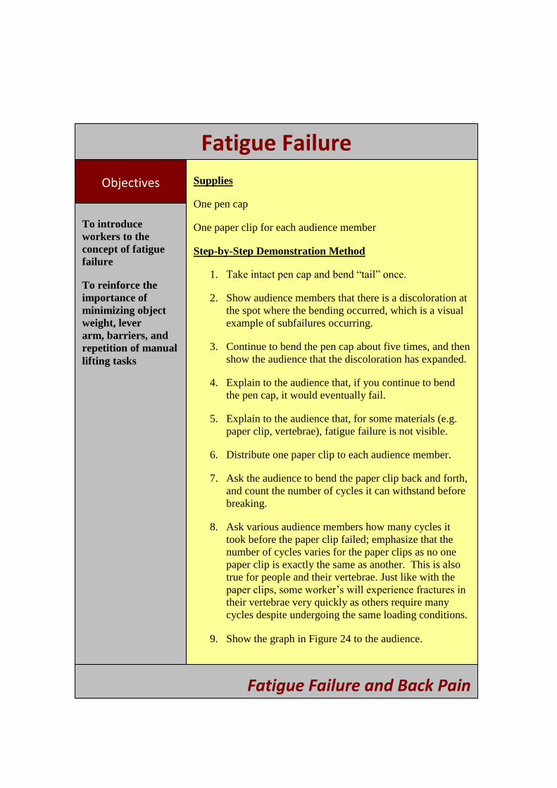
To introduce workers to the concept of fatigue failure
To reinforce the importance of minimizing object weight, lever arm, barriers, and repetition of manual lifting tasks
Supplies
One pen cap
One paper clip for each audience member
Step-by-Step Demonstration Method
1. Take intact pen cap and bend ―tail‖ once.
2. Show audience members that there is a discoloration at the spot where the bending occurred, which is a visual example of subfailures occurring.
3. Continue to bend the pen cap about five times, and then show the audience that the discoloration has expanded.
4. Explain to the audience that, if you continue to bend the pen cap, it would eventually fail.
5. Explain to the audience that, for some materials (e.g. paper clip, vertebrae), fatigue failure is not visible.
6. Distribute one paper clip to each audience member.
7. Ask the audience to bend the paper clip back and forth, and count the number of cycles it can withstand before breaking.
8. Ask various audience members how many cycles it took before the paper clip failed; emphasize that the number of cycles varies for the paper clips as no one paper clip is exactly the same as another. This is also true for people and their vertebrae. Just like with the paper clips, some worker’s will experience fractures in
their vertebrae very quickly as others require many cycles despite undergoing the same loading conditions.
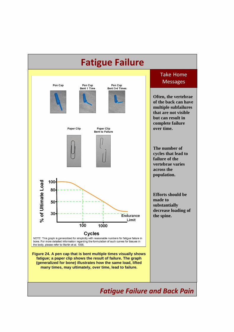
9. Show the graph in Figure 24 to the audience.
Fatigue Failure and Back Pain
38

Fatigue Failure
10. Explain that every type of material has an ultimate load (i.e., the load at which it fails when that load is applied only once). The graph in Figure 24 illustrates the amount of loads the spine can handle without breaking. Because every spine is unique, the ultimate load varies somewhat for each spine. Thus, the y-axis of this graph represents the percentage of ultimate load. The x-axis represents the number of cycles a load was applied. For example, if you applied a load to a spine that was 80% of its ultimate load, you would be able to apply that load 100 times before the spine would fail. Likewise, if you applied a load that was only 50% of its ultimate load, you could apply that load 1,000 times before failure. If you applied a load that was only 30% of its ultimate load, you could complete an infinite number of loading cycles without the spine ever failing.
11. Explain to the audience that this means they are not ―doomed to having a back injury.‖ Rather, if the load applied to the spine is decreased substantially, they could perform their job an infinite number of times and never injure their spine. You may also increase your core strength to better handle loads—a balanced body in terms of abdominal and back strength makes a more stable core when trained together.
12. Discuss ways to reduce the load applied to the spine, such as decreasing the weight of the object, reducing the moment arm (see Section 6), removing barriers, and eliminating twisting and back flexion.
Fatigue Failure and Back Pain
39
Fatigue Failure Take -Home Messages
Often, the vertebrae of the back can have multiple subfailures that are not visible but can result in complete failure over time.
The number of cycles that lead to failure of the vertebrae varies across the population.
Efforts should be made to substantially decrease loading of the spine.
Figure 24. A pen cap that is bent multiple times visually shows fatigue; a paper clip shows the result of failure. The graph (generalized for bone) illustrates how the same load, lifted
many times, may ultimately, over time, lead to failure.
Fatigue Failure and Back Pain
40
SECTION 6: MOMENT ARMS AND LIFTING
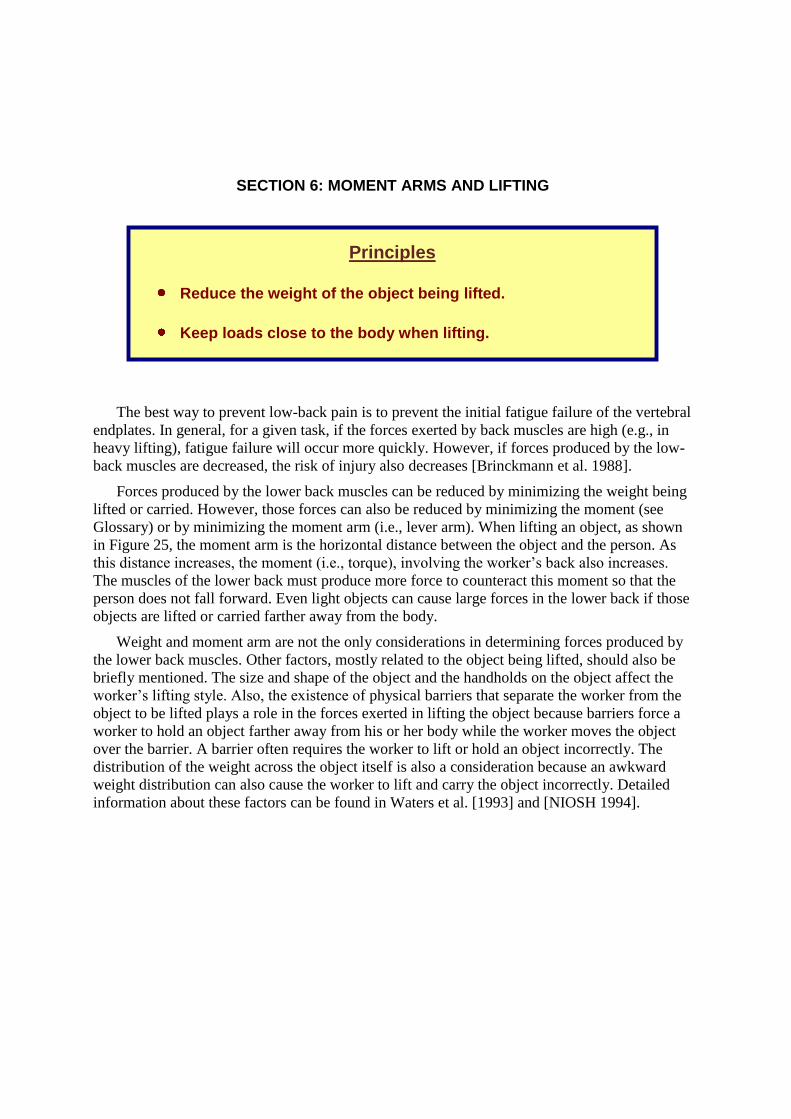
Principles
Reduce the weight of the object being lifted.
Keep loads close to the body when lifting.
The best way to prevent low-back pain is to prevent the initial fatigue failure of the vertebral endplates. In general, for a given task, if the forces exerted by back muscles are high (e.g., in heavy lifting), fatigue failure will occur more quickly. However, if forces produced by the low-back muscles are decreased, the risk of injury also decreases [Brinckmann et al. 1988].
Forces produced by the lower back muscles can be reduced by minimizing the weight being lifted or carried. However, those forces can also be reduced by minimizing the moment (see Glossary) or by minimizing the moment arm (i.e ., lever arm). When lifting a n object, as shown in Figure 25, the moment arm is the horizontal distance between the object and the person. As this distance increases, the moment (i.e., torque), involving the worker’s back also increases.
The muscles of the lower back must produce more force to counteract this moment so that the person does not fall forward. Even li ght objects can cause large forces in the lower back if those objects are lifted or carried farther away from the body.
Weight and moment arm are not the only considerations in determining forces produced by the lower back muscles. Other factors, mostly related to the object being lifted, should also be briefly mentioned. The size and shape of the object and the handholds on the object affect the worker’s lifting style. Also, the existence of physical barriers that separate the worker from the object to be lifted plays a role in the forces exerted in lifting the object because barriers force a worker to hold an object farther away from his or her body while the worker moves the object over the barrier. A barrier often requires the worker to lift or hold an object incorrectly. The distribution of the weight across the object itself is also a consideration because an awkward weight distribution can also cause the worker to lift and carry the object incorrectly. Detailed information about these factors can be found in Waters et al. [1993] and [NIOSH 1994].
41
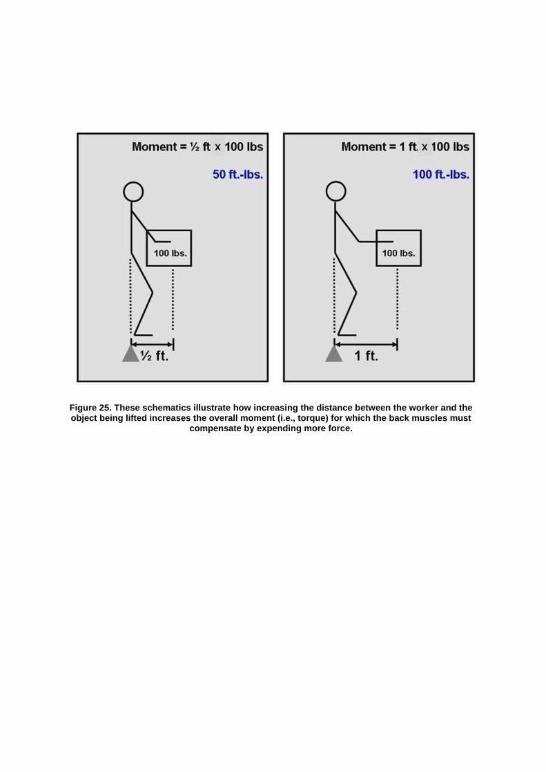
Figure 25. These schematics illustrate how increasing the distance between the worker and the object being lifted increases the overall moment (i.e., torque) for which the back muscles must
compensate by expending more force.
42

Moment Arms
Objectives
To introduce workers to the concept of moments and moment arms
Supplies
A moment-arm simulator (Figure 26)
Three rectangular blocks of equal weight
Step-by-Step Demonstration Method. See Introduction video.
1. Place two of the three blocks on opposite sides of the fulcrum at equal distance from the fulcrum of the moment-arm simulator.
2. The moment-arm simulator should be perfectly balanced.
3. Move one of the blocks to twice the distance from the fulcrum.
4. Note that the ―see-saw‖ will tip towards the block that is furthest from the fulcrum. This occurs because the moment arm (i.e., the distance from fulcrum) is larger for this block. Thus, the moment, or torque, produced by this block is greater than that of the second block.
5. Add a second block to the side of the moment-arm simulator with the shortest distance from the fulcrum.
6. Note that the moment-arm simulator will now balance again, indicating that it is capable of withstanding twice as much force because the moment arm is half as long.
7. Discuss with the audience the point that the weight of the object is not the only consideration in producing forces on the body—as the horizontal distance increases, the resulting moment also increases.
Moment Arms and Lifting
43

Moment Arms Take -Home Messages
During manual material handling, reduce the moment arm as much as possible by reducing the load on the lower back and keeping the load close to the body.
Design workstations and storage facilities that allow the worker to keep objects close to his or her body when lifting them.
Figure 26. A moment-arm simulator showing that more force/weight (W; arrow indicates direction of force) is needed to balance the “see saw” if the moment arm (L) is shorter on one
side of the fulcrum as compared to the other side.
Moment Arms and Lifting
44

Moment Arms and the Low Back
Objectives
To introduce the effect of moment arm on forces exerted by lower back muscles when lifting or carrying an object
To emphasize that the weight of an object is not the only consideration in determining forces produced by the lower back; the position of the weight of the load in relation to the body also affects the forces and stresses in the low back
To discuss factors that may increase the moment arm and the resulting forces exerted by the low-back muscles
Supplies
A moment-arm simulator made from aluminum (Figure 27)
Spring scale
Metal weights
Step-by-Step Demonstration Method. See Introduction video.
1. Place known weights midway between the fulcrum and the end of the horizontal bench.
2. The moment-arm simulator should be perfectly balanced as the spring scale undergoes loading.
3. Note the force in the spring scale.
4. Move the weights farther away from the fulcrum.
5. Again, the moment-arm simulator should be perfectly balanced; however, the force in the spring scale should increase.
6. Discuss with the audience that the only change made was the moment arm, indicating that weight is not the only factor affecting how much force must be exerted.
7. Relate the spring scale to the low-back muscles, fulcrum to the vertebrae, and weight to an object being carried.
8. Discuss with the audience how the forces exerted by the low-back muscles must increase as an object is moved farther away from the pelvis.
Moment Arms and Lifting
45
Moment Arms and the Low Back
Take -Home Messages
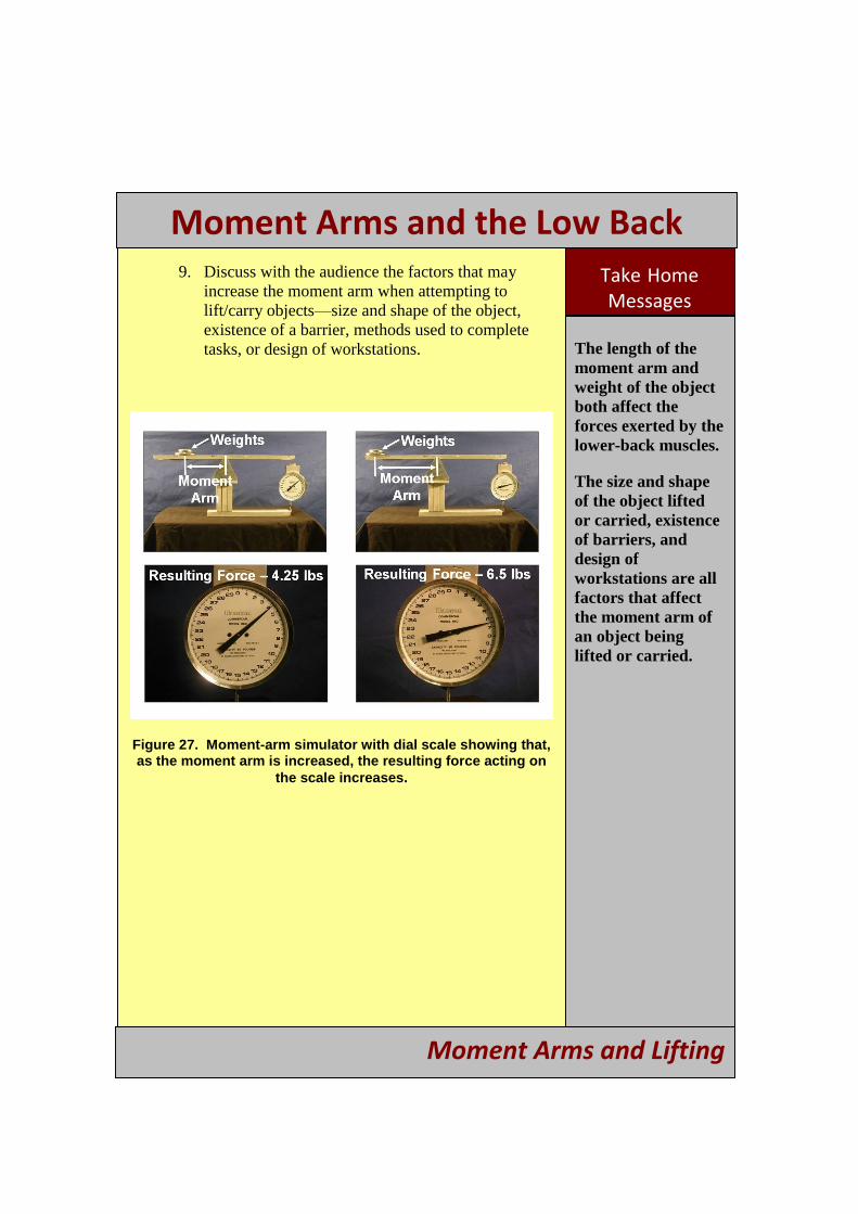
The length of the moment arm and weight of the object both affect the forces exerted by the lower-back muscles.
The size and shape of the object lifted or carried, existence of barriers, and design of workstations are all factors that affect the moment arm of an object being lifted or carried.
9. Discuss with the audience the factors that may increase the moment arm when attempting to lift/carry objects—size and shape of the object, existence of a barrier, methods used to complete tasks, or design of workstations.
Figure 27. Moment-arm simulator with dial scale showing that, as the moment arm is increased, the resulting force acting on
the scale increases.
Moment Arms and Lifting
46

APPENDIX A: SUGGESTED SUPPLIES
All supplies needed for the demonstrations are included in the following list. Purchasing information is also provided, although most of the supplies can be purchased at hardware
1 stores .
1 The National Institute for Occupational Safety and Health does not endorse any manufacturer or supplier of these products. When using the general guidelines provided above, it is the responsibility of the end user to assess the products they intend to purchase and use.
47
Hand dynamometer (grip type)—evaluates grip strength for multiple grip widths (Figure A-2 A and B).
o This device measures the hand force generated by a power grip (i.e., where the user curls the fingers towards the palm). The force generated is displayed on a dial or on a digital output. If attempting to locate this device using an Internet search engine (e.g., www.google.com, www.yahoo.com, www.ask.com), the following phrase may be helpful when searching for a vendor—―hand dynamometer grip width.‖ You may also consider adding the keywords
―adjustable‖ or ―multiple‖. This item costs from $225 to $375, depending on the
manufacturer and the number of grip widths the dynamometer can evaluate. Among common suppliers of dynamometers, identified from an internet search, are Baseline Tool Company, Medline Industries, and Sammons Preston Rolyan.
o This device may also be used to evaluate pinch grip, by adjusting the width of the grip to its minimum.
Hand dynamometer (pinch type)—evaluates pinch grip strength (Figure A-2C).
o This device measures the force generated by a pinch grip (i.e., where the user presses the thumb against the index finger). The force generated is displayed on a dial or on a digital output. If attempting to find this device using an Internet search engine (e.g., www.google.com, www.yahoo.com, www.ask.com), the following phrase may be helpful when searching for a vendor—―dynamometer pinch grip.‖ You may also consider adding the keywords ―strength‖ or ―price.‖
This item costs from $250 to $350 depending on the manufacturer and the maximum force measured by the device. Among common supplier of pinch type dynamometers, identified from an internet search, are Dynatronics, Baseline Tool Company, and Jamar.
Traditional screwdrivers—varying handle diameters (Figure A-2D).
o Traditional screwdrivers are designed with a hard, plastic handle. Many manufacturers offer screwdrivers with various handle diameters and working-end size (i.e., a larger handle diameter corresponds to a larger working-end size). However, other manufacturers attempt to keep the handle diameter as large as
possible. Screwdrivers with different handle diameters, but similar-sized working ends, should be obtained for the demonstrations. These items may be purchased at any standard hardware store for about $20 each.
Screwdriver—can convert to either an inline or pistol grip (Figure A-2 E a nd F).
o Screwdrivers that can be adjusted from an inline to a pistol grip are available at most standard hardware stores. This item costs approximately $50.
Electric drill—can be held with both hands when additional support is needed (Figure A-2 G a nd H).
o Electric drills that have a second handle to allow support from both hands may be purchased at any hardware store. This item costs approximately $100 to $200.
Needle-nose pliers—with and without a spring-loaded handle (Figure A-2 I and J).
Needle-nose pliers may be purchased at a hardware store. This item may be purchased for approximately $20.
Portable electromyography (EMG) device—battery-operated device with audible feedback where the intensity of the sounds produced by the device increases with increased muscle activity (Figure A-2K).
o When using electrodes placed on the surface of the skin (with tape similar to a Band-Aid), the amount of muscle activity may be measured when a worker is at rest and while performing a task. The amount of muscle activity experienced by the worker is conveyed with an audible sound. As muscle activity increases, so does the intensity of the sound produced by the device. If attempting to locate this device using an Internet search engine (e.g., www.google.com, www.yahoo.com, www.ask.com), the following phrase may be helpful when finding a vendor—―portable EMG audible‖. This item costs from $300 to $450 depending on the manufacturer. For the purpose of this document, the ―pocket
ergometer‖ from AliMed was used; however, NIOSH does not endorse any 1specific manufacturer . However, a supply of disposable surface electrodes must
also be purchased. These typically come in packs of 50, 100, or 1,000. A pack of 100 costs about $10. If using an Internet search engine, the following phrase may be helpful—―EMG disposable surface electrode.‖ Among the common suppliers of electrodes, identified from an internet search, are Nikomed USA, Inc. and Biopac Systems, Inc.
o The product directions should be followed for the specific device purchased. In general, the device will likely consist of a small box, a cable with three leads at the end, and a package of electrodes. The small box houses the signal processing and output capabilities of the unit. Three electrodes should be placed on the skin above the same muscle or muscle group. Once affixed to the skin, the leads of the cable should be connected to the electrodes. The cable will likely consist of two red leads and one black lead. The black lead should be connected to the
48

electrode that is midway between the other two (Figure A-2K). The red leads should be connected to the electrodes on either side. Once the device is turned on, the audible output may need to be adjusted based on the amount of activity associated with the specific muscle or muscle group being evaluated.
Standard weights or custom-made blocks (3.5 in x 5 in x 1 in) – four steel blocks weighing approximately 5 lbs each.
o Standard weights may be purchased at any store that sells supplies for weight training.
o Custom steel blocks can be constructed from steel stock purchased at most larger hardware stores. Some also offer the service of cutting these items to size for their customers. Other materials may also be used for this task as long as the weight and size of all blocks are uniform.
Dial scale—must have the ability to attach to objects at either end of the scale (Figure A2L).
o This item is best purchased using an online source. Use an Internet search engine (e.g., www.google.com, www.yahoo.com, www.ask.com). The following search phrase may be helpful when finding a vendor—―hanging spring dial scale.‖ This item may cost from $10 to $50, depending on the manufacturer and the maximum force that the device measures. For these demonstrations, a 10-lb capacity or greater is recommended. Among the common suppliers of this device, identified from an internet search, are Detecto, Global Industrial, Calibex, and Salter Brecknell Mechanical Scales.
Moment-arm simulator that is 40 in long (20 in from fulcrum to end x 5 in width)—must be able to support the weight of the four steel blocks (Figures A-1 a nd A-2L).
Figure A-1. Dimensions for the moment-arm simulator.
49

o This item may be custom-made. Suggested dimensions complement the dimensions provided above for the steel blocks. Additionally, this size allows the device to be viewed by all audience members when training is given in a room that is the size of a standard classroom. The ―see-saw‖ should be able to move freely about its fulcrum. Aluminum stock may be purchased at most larger hardware stores; some stores also offer the service of cutting these items to size for their customers. Alternatively, this device may be made from wood at a less expensive cost. Materials other than aluminum may be used. Aluminum was suggested due to its relatively light weight and low cost. You should mark the locations along the see-saw that are 10 inches and 15 inches from the fulcrum as a visual aid for placing the steel blocks during the demonstrations.
o Other similar devices may be purchased for less than $100. An internet search found that common suppliers included Fisher Scientific.
Pen cap—must be plastic and easy to bend (Figure A-2M)
o Remove from the top of a pen
Paper clip—standard size (Figure A-2N)
o Metal, uncoated paper clips
50
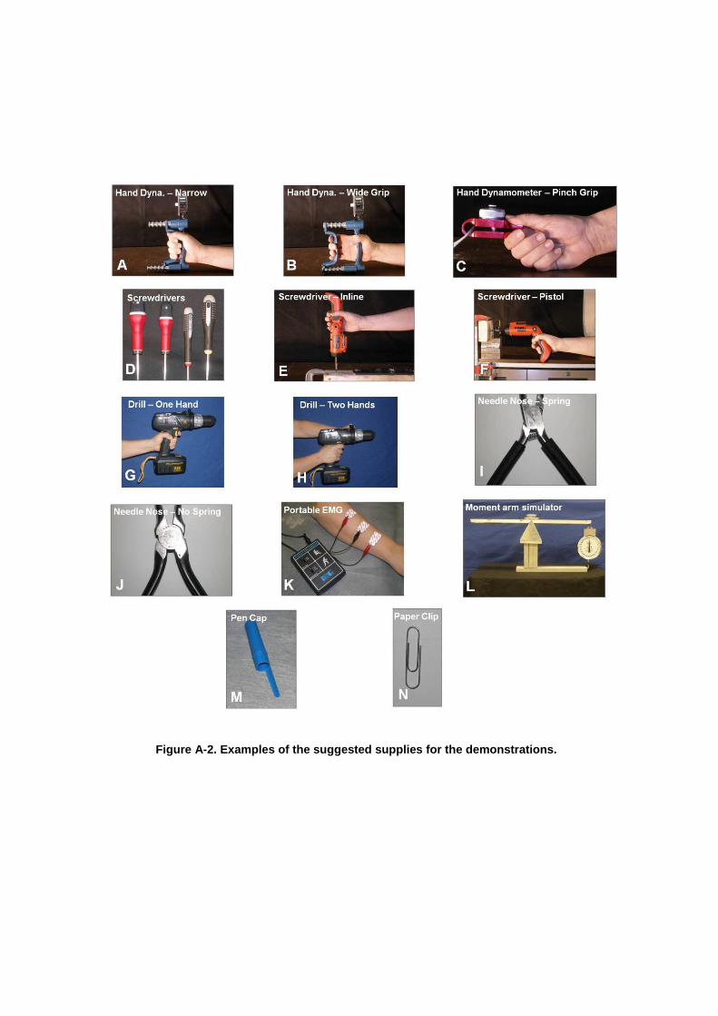
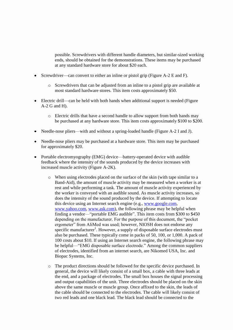
Figure A-2. Examples of the suggested supplies for the demonstrations.
51
APPENDIX B: USEFUL IMAGES FOR HANDOUTS
52

53

54

55
vi | Observation-Based Posture Assessment: Review of Current Practice and Recommendations for Improvement Observation-Based Posture Assessment: Review of Current Practice and Recommendations for Improvement | vii
GLOSSARY
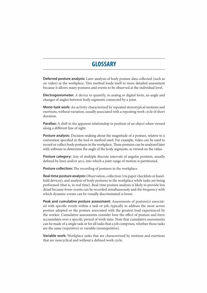
Deferred posture analysis: Later analysis of body posture data collected (such as on video) in the workplace. This method lends itself to more detailed assessment because it allows many postures and events to be observed at the individual level.
Electrogoniometer: A device to quantify, in analog or digital form, an angle and changes of angles between body segments connected by a joint.
Mono-task work: An activity characterized by repeated stereotypical motions and exertions, without variation, usually associated with a repeating work cycle of short duration.
Parallax: A shift in the apparent relationship in position of an object when viewed along a different line of sight.
Posture analysis: Decision-making about the magnitude of a posture, relative to a convention specified in the tool or method used. For example, video can be used to record or collect body postures in the workplace. These postures can be analyzed later with software to determine the angle of the body segments, as viewed on the video.
Posture category: Any of multiple discrete intervals of angular position, usually defined by lines and/or arcs, into which a joint range of motion is partitioned.
Posture collection: The recording of postures in the workplace.
Real-time posture analysis: Observation, collection (via paper checklists or hand-held devices), and analysis of body postures in the workplace while tasks are being performed (that is, in real time). Real-time posture analysis is likely to provide less detail because fewer events can be recorded simultaneously and the frequency with which dynamic events can be visually discriminated is lower.
Peak and cumulative posture assessment: Assessments of posture(s) associat-ed with specific events within a task or job, typically to address the most severe posture adopted or the posture associated with the greatest load experienced by the worker. Cumulative assessments consider how the effect of posture and force accumulates over a specific period of work time. Note that cumulative assessments can be made of a single task or for all tasks that a job comprises, whether those tasks are the same (repetitive) or variable (nonrepetitive).
Variable work: Workplace tasks that are characterized by motions and exertions that are noncyclical and without a defined work cycle.
Observation-Based Posture Assessment: Review of Current Practice and Recommendations for Improvement | 1
BACKGROUND
The purpose of this document is to help prac-titioners assess working posture for the pre-vention and control of occupational muscu-loskeletal disorders (MSDs). Quantitative or semiquantitative descriptions of posture are inputs to many job analysis tools applied in MSD prevention and control. Studies of the relationship between risk factors (such as pos-ture, repetition, and force) and resulting MSD prevalence have used various approaches to characterizing working posture, including observation-based methods. Posture classifi-cation by systematic observation of a worker is commonly used in research and by practi-tioners, such as ergonomists, industrial hy-gienists, and safety professionals, to help in-form job design decisions and establish safe work limits to reduce MSD injury risk in the workplace.
Just as direct measurement methods have lim-itations in their ability to accurately assess expo-sure, it is equally important to consider the lim-itations of an observer in discriminating among posture categories (levels) that reflect increased exposure severity. Some estimation “error” is inherent in the use of any observation-based as-sessment tool. Recent studies have identified an approach to the selection of posture categories that reduces posture classification errors and im-proves efficiency, thereby providing an opportu-nity to improve posture assessment in the work-place. This report presents this recent evidence, which forms the basis for an emerging practice to optimize observation-based posture assessment performance and efficiency. A secondary purpose of the document is to help practitioners improve posture recording and analysis using observation- based assessment methods (See page 5).
Overexertion injuries to the musculoskeletal system (including those from lifting, pushing, pulling, holding, carrying, or throwing) cost U.S. businesses $12.75 billion (U.S.) in direct costs in 2009 and accounted for more than a quarter of the overall na-tional burden [Liberty Mutual Research Institute for Safety 2011]. The situation is sim-ilar in Canada where a 2005 labor market report estimated direct and indirect cost of musculoskeletal disorders (MSDs) at $20 billion (CDN) [McGee et al. 2011]. In Canada, 26.4% of all injuries at work in 2003 were due to overexertion [Wilkins and Macken-zie 2007]. In Ontario, sprains and strains accounted for 50.2% of lost-time claims, and 46.6% of these claims were due to events such as overexertion, static postures, and repetitive motions [WSIB 2009]. In Manitoba, 60% of all lost time injuries are MSDs.
2 | Observation-Based Posture Assessment: Review of Current Practice and Recommendations for Improvement Observation-Based Posture Assessment: Review of Current Practice and Recommendations for Improvement | 3
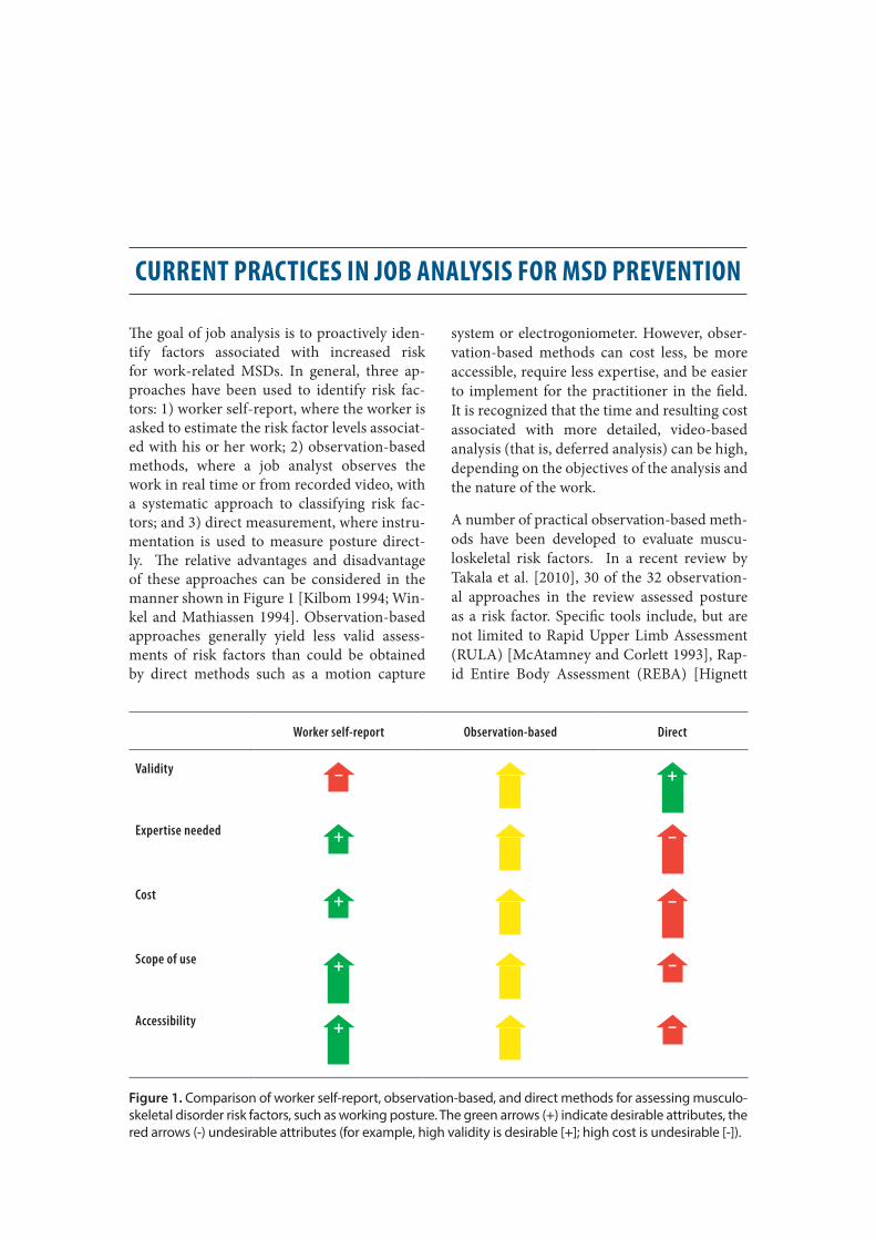
Figure 1. Comparison of worker self-report, observation-based, and direct methods for assessing musculo-skeletal disorder risk factors, such as working posture. The green arrows (+) indicate desirable attributes, the red arrows (-) undesirable attributes (for example, high validity is desirable [+]; high cost is undesirable [-]).
CURRENT PRACTICES IN JOB ANALYSIS FOR MSD PREVENTION
The goal of job analysis is to proactively iden-tify factors associated with increased risk for work-related MSDs. In general, three ap-proaches have been used to identify risk fac-tors: 1) worker self-report, where the worker is asked to estimate the risk factor levels associat-ed with his or her work; 2) observation-based methods, where a job analyst observes the work in real time or from recorded video, with a systematic approach to classifying risk fac-tors; and 3) direct measurement, where instru-mentation is used to measure posture direct-ly. The relative advantages and disadvantage of these approaches can be considered in the manner shown in Figure 1 [Kilbom 1994; Win-kel and Mathiassen 1994]. Observation-based approaches generally yield less valid assess-ments of risk factors than could be obtained by direct methods such as a motion capture
system or electrogoniometer. However, obser-vation-based methods can cost less, be more accessible, require less expertise, and be easier to implement for the practitioner in the field. It is recognized that the time and resulting cost associated with more detailed, video-based analysis (that is, deferred analysis) can be high, depending on the objectives of the analysis and the nature of the work.
A number of practical observation-based meth-ods have been developed to evaluate muscu-loskeletal risk factors. In a recent review by Takala et al. [2010], 30 of the 32 observation-al approaches in the review assessed posture as a risk factor. Specific tools include, but are not limited to Rapid Upper Limb Assessment (RULA) [McAtamney and Corlett 1993], Rap-id Entire Body Assessment (REBA) [Hignett
Worker self-report Observation-based Direct
Validity
Expertise needed
Cost
Scope of use
Accessibility

2 | Observation-Based Posture Assessment: Review of Current Practice and Recommendations for Improvement Observation-Based Posture Assessment: Review of Current Practice and Recommendations for Improvement | 3
and McAtamney 2000], Strain Index [Moore and Garg 1995], Occupational Repetitive Actions In-dex (OCRA) [Occhipinti 1998], TRAC [van der Beek et al. 1992] and other approaches reported in scientific publications [Armstrong et al 1982; Genaidy et al 1993; Seth et al 1999]. Posture is a key input in these analysis tools in which the an-alyst classifies a body segment position which is partitioned into posture categories. Each posture category represents a certain portion of the range of motion. (Table 1 shows the number of posture categories for the methods above.)
Although posture is recognized as a risk factor in all of these methods, it is often difficult to compare results among studies using the var-ious methods. One reason for this is that pos-tures have not been standardized across the methods in the size, and therefore number, of posture categories used to quantify working posture [Andrews et al. 2008a, 2008b; Keyser-ling 1986; Juul-Kristensen et al. 2001; Lowe 2004a; Weir et al. 2011]. One reason for the lack of consistency between studies is the nature of
the job or task and that the characteristics of the physical exposures in the job affect the decision about type of assessment, sampling approach, and summary measures to be adopted. There are several types of assessments in which working posture is classified on the basis of visual obser-vation, as shown in Appendix A. Though direct measurement technologies are improving, cur-rently many practitioners are assessing physical job demands by way of observational judgment. The following section presents posture categories for observation-based posture classification that have been demonstrated to optimize observer performance and efficiency. These categories are defined for the spatial description of individual posture observations, in which a still image or isolated video frame of an event is defined. It is beyond the scope of this report to address statis-tical treatment of posture sampled over time. As the science, knowledge base, and measurement technologies relevant to posture assessment in MSD prevention and control are further devel-oped, best practices will continue to evolve.
Table 1. Selected methods for MSD risk assessment and their associated number of posture categories. Each value represents the number of categories into which the posture range is partitioned.
Method*
Trunk Shoulder Elbow Forearm Wrist
FlexionLateral
bend TwistFlexion/
extensionAbduction/ adduction Flexion
Pronation/supination
Flexion/extension
Radial/ ulnar
deviation
(1) 5 2 3 4 4 2(2) 5 2(3) 4 2 2 2
(4) 3 2 2 2(5) 4 2 2 5 2 3 2 4 2(6) 6 4† 4 3 5 3(7) 4 2 2 4 2 3 2 5 2(8) 4 4 4 2 3 5 5
Figure 2, present
4 3 5 5 4
*Method definitions and sources: (1) RULA—McAtamney and Corlett (1993); (2) Strain Index—Moore and Garg (1995); (3) TRAC—van der Beek et al. (1992); (4) OCRA—Occhipinti (1998); (5) REBA—Hignett and McAtamney (2000); (6) Armstrong et al. (1982); (7) Genaidy et al. (1993); (8) Seth et al. (1999).
†Horizontal abduction/adduction.
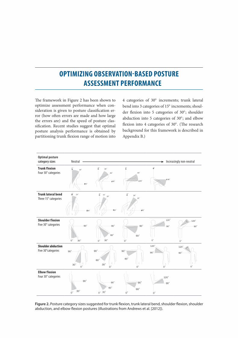
4 | Observation-Based Posture Assessment: Review of Current Practice and Recommendations for Improvement
OPTIMIZING OBSERVATION-BASED POSTURE ASSESSMENT PERFORMANCE
The framework in Figure 2 has been shown to optimize assessment performance when con-sideration is given to posture classification er-ror (how often errors are made and how large the errors are) and the speed of posture clas-sification. Recent studies suggest that optimal posture analysis performance is obtained by partitioning trunk flexion range of motion into
4 categories of 30° increments; trunk lateral bend into 3 categories of 15° increments; shoul-der flexion into 5 categories of 30°; shoulder abduction into 5 categories of 30°; and elbow flexion into 4 categories of 30°. (The research background for this framework is described in Appendix B.)
Optimal posture category sizes Neutral Increasingly non-neutral
Trunk f lexionFour 30° categories
30˚
90˚
0˚
60˚
30˚
90˚
0˚
60˚
90˚
0˚ 0˚
90˚
Trunk lateral bendThree 15° categories
15˚
90˚
0˚
30˚15˚
90˚
0˚
45˚
30˚
90˚
0˚
Shoulder f lexionFive 30° categories
30˚0˚
90˚
60˚
30˚0˚
90˚
60˚
0˚
90˚
0˚
90˚
120˚
0˚
90˚
120˚
Shoulder abductionFive 30°categories
0˚
90˚
30˚0˚
90˚
60˚
30˚
90˚
60˚
0˚ 0˚
90˚
120˚
0˚
90˚
120˚
Elbow f lexionFour 30° categories
90˚
30˚0˚
90˚
60˚
30˚0˚
60˚0˚
90˚ 90˚
120˚
0˚
Figure 2. Posture category sizes suggested for trunk flexion, trunk lateral bend, shoulder flexion, shoulder abduction, and elbow flexion postures (illustrations from Andrews et al. [2012]).
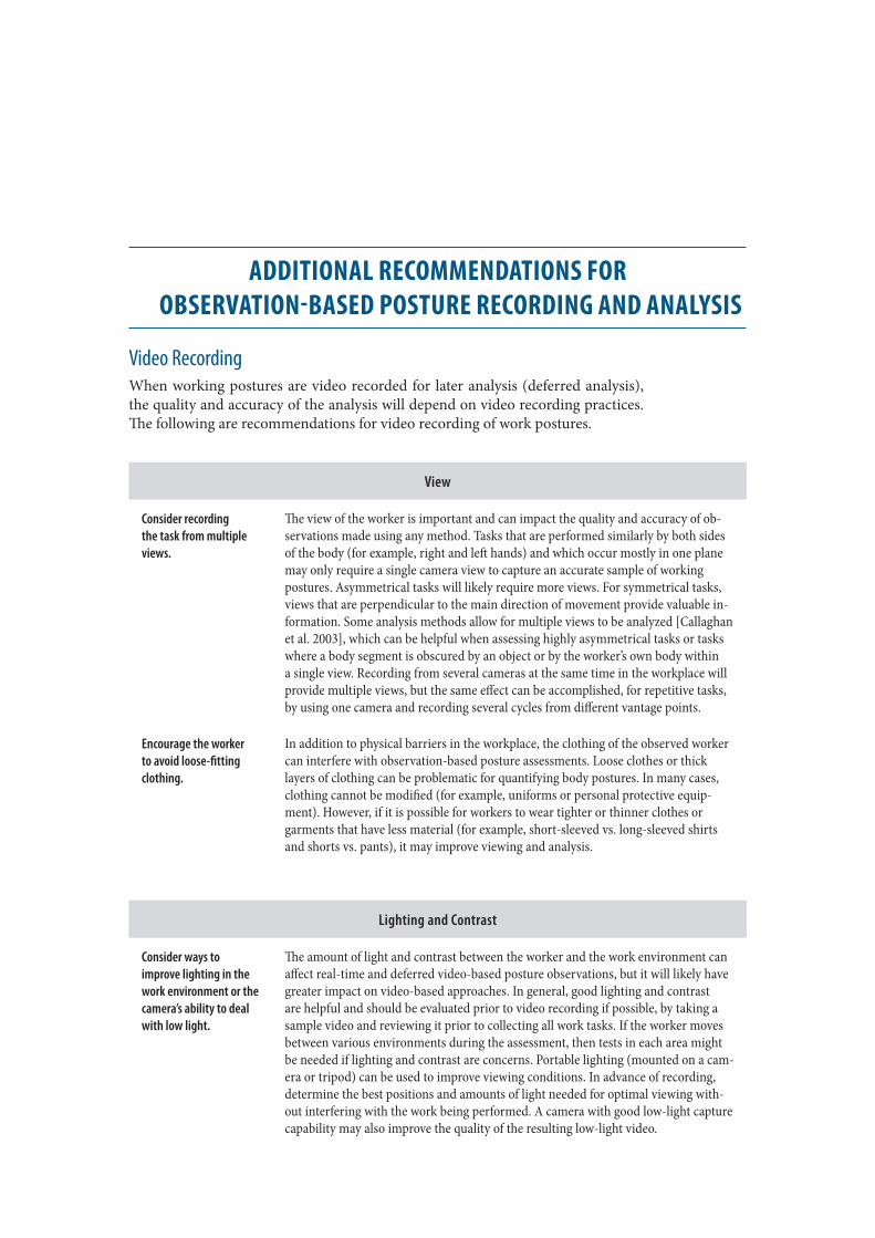
Observation-Based Posture Assessment: Review of Current Practice and Recommendations for Improvement | 5
ADDITIONAL RECOMMENDATIONS FOR OBSERVATION-BASED POSTURE RECORDING AND ANALYSIS
Video RecordingWhen working postures are video recorded for later analysis (deferred analysis), the quality and accuracy of the analysis will depend on video recording practices. The following are recommendations for video recording of work postures.
View
Consider recording the task from multiple views.
The view of the worker is important and can impact the quality and accuracy of ob-servations made using any method. Tasks that are performed similarly by both sides of the body (for example, right and left hands) and which occur mostly in one plane may only require a single camera view to capture an accurate sample of working postures. Asymmetrical tasks will likely require more views. For symmetrical tasks, views that are perpendicular to the main direction of movement provide valuable in-formation. Some analysis methods allow for multiple views to be analyzed [Callaghan et al. 2003], which can be helpful when assessing highly asymmetrical tasks or tasks where a body segment is obscured by an object or by the worker’s own body within a single view. Recording from several cameras at the same time in the workplace will provide multiple views, but the same effect can be accomplished, for repetitive tasks, by using one camera and recording several cycles from different vantage points.
Encourage the worker to avoid loose-fitting clothing.
In addition to physical barriers in the workplace, the clothing of the observed worker can interfere with observation-based posture assessments. Loose clothes or thick layers of clothing can be problematic for quantifying body postures. In many cases, clothing cannot be modified (for example, uniforms or personal protective equip-ment). However, if it is possible for workers to wear tighter or thinner clothes or garments that have less material (for example, short-sleeved vs. long-sleeved shirts and shorts vs. pants), it may improve viewing and analysis.
Lighting and Contrast
Consider ways to improve lighting in the work environment or the camera’s ability to deal with low light.
The amount of light and contrast between the worker and the work environment can affect real-time and deferred video-based posture observations, but it will likely have greater impact on video-based approaches. In general, good lighting and contrast are helpful and should be evaluated prior to video recording if possible, by taking a sample video and reviewing it prior to collecting all work tasks. If the worker moves between various environments during the assessment, then tests in each area might be needed if lighting and contrast are concerns. Portable lighting (mounted on a cam-era or tripod) can be used to improve viewing conditions. In advance of recording, determine the best positions and amounts of light needed for optimal viewing with-out interfering with the work being performed. A camera with good low-light capture capability may also improve the quality of the resulting low-light video.

6 | Observation-Based Posture Assessment: Review of Current Practice and Recommendations for Improvement Observation-Based Posture Assessment: Review of Current Practice and Recommendations for Improvement | 7
Camera Movement, Stability, and Framing
Minimize unnecessary camera movement.
Observation-based posture assessment methods such as RULA [McAtamney and Corlett 1993] or 3DMatch [Callaghan et al. 2003] require observers to select posture categories that correspond to the actual body postures seen in real-time (RULA) or previously recorded video (RULA, 3DMatch). These approaches give the observer the freedom to move around the workplace so that an optimal view can be achieved at all times. However, posture analysis accuracy can be affected by how stable the camera view is. If the task requirements limit the range of motion of the work, a tripod could be used to ensure that the camera view remains consistent and smooth. If the worker has to move beyond the view of a stationary camera, the camera operator will need to move with the worker and try to keep the camera as stable as possible. Camera supports, monopods, or even a solid surface on which to rest the camera while it is strapped to the hand can help reduce camera shake, which can improve later viewing.
Zoom in on limb seg-ments so that the joint of interest is as large as possible in the camera field of view.
It is also important to make sure that the body segments being assessed are in full view within the frame of the video. It may be difficult, because of obstructions and movement in the workplace, to get close to the worker without interfering. Use the zoom function to fill the frame as much as possible so that you are located at a safe distance and the view is not restricted. Because of the smaller size of the hand segment relative to the trunk and arm segments, a zoomed-in view of the hand is desirable when observation-based analyses of wrist posture are conducted. For more dynamic work activities, this may be difficult, because the hands may be moving in space and may move out of the field of view of a fixed-position camera. More posture classification errors can be expected when postures of the smaller limb segments and joints are estimated.
The best camera position is perpendicular to the plane of the joint(s) of interest.
Video images represent posture two-dimensionally, which challenges the observer if the camera view is not perpendicular to the plane of motion of interest at a specific joint. Perspective errors (parallax) can be introduced by the two-dimensional repre-sentation of posture in three-dimensional space and by a camera that is not ideally positioned with respect to the posture of interest. If the camera view is perpendicular to the plane of motion of the joint of interest, then a more accurate assessment of the angle can be made. When the camera view is not perpendicular to this plane of motion, perspective error may result. However, studies have shown that accurate posture classification can be attained in these situations [Sutherland et al. 2007] and that estimation error due to parallax is often less than would be predicted by the spatial relationship between the camera and the joint observed [Lau and Armstrong 2011]. Nonetheless, when possible, the camera should be oriented perpendicularly to the plane of motion to obtain an ideal view.
Consider acquiring video from multiple camera positions when an optimal view cannot be achieved.
If the ideal camera perspective cannot be achieved, then samples of the job can be obtained from multiple perspectives-either with two cameras simultaneously or with a single camera capturing different perspective views sequentially.
6 | Observation-Based Posture Assessment: Review of Current Practice and Recommendations for Improvement Observation-Based Posture Assessment: Review of Current Practice and Recommendations for Improvement | 7
Duration of Observation
Jobs with more variable postures may require longer observation periods.
The length of time for which postures should be observed depends on the type of task(s) the worker is performing and the nature of the analysis. If the analysis is for tasks that require the worker to do the same things repetitively, then observing only a few cycles or repetitions of the repetitive task is likely sufficient. Similarly, when evaluating the peak stress of a particular task, only a short period of time may need to be analyzed. Identifying the task associated with peak stress, particularly when this task occurs infrequently, often requires discussion with the worker(s). In cases where the work is nonrepetitive or when the cumulative effects of posture exposure are to be assessed, the work must be observed over a longer period of time. Generally, the more variable the work in terms of posture, the more observation time is needed to obtain a representative sample of the posture.
Conduct postural assessments of multiple workers, with particular emphasis on the workers exhibiting the most severe postures.
Workers vary in their body size (anthropometry) and work technique. These differ-ences can result in posture and physical stresses that vary among workers performing similar (or identical) jobs. It is important to assess posture for multiple workers, preferably closer to the extremes in sizes, to ensure that the assessment of posture reflects that of the most severe cases.
8 | Observation-Based Posture Assessment: Review of Current Practice and Recommendations for Improvement Observation-Based Posture Assessment: Review of Current Practice and Recommendations for Improvement | 9
Posture Analysis The following are practical recommendations to improve analysis of posture from a video that has been recorded previously.
The definition of postures simplifies the repre-sentation of joint position for the purpose of characterizing postural stress.
Observation-based posture assessment can be enhanced by the definitions used for the postures themselves. For example, for the purpose of observational assessments, shoulder posture is typically simplified by considering a single “humeral-thoracic” joint – the angular position of the arm with respect to the trunk. This is a biomechanical simplification of the complexity of the shoulder girdle, which consists of multiple joints. Similarly, segment motions throughout the lumbar and thoracic spine are typically simplified in the definition of trunk postures to include trunk flexion/extension (or sometimes trunk inclination), trunk lateral bend, and trunk rotation. These biomechanical simplifications make it easier to visually estimate back posture for prediction of injury risk. They also require a compromise in the level of biomechanical detail that can be obtained.
Visual reference of posture angles improves performance.
The observation of posture can be enhanced by providing the analyst with visual reference of the joint angles defining the posture cate-gories. These are graphical representations of the posture category boundaries. The analyst’s task is then one of matching the observed posture to the reference images rather than the more challenging task of directly estimating an angle between limb segments. Recent work has shown that adding a more salient border, either mono-chrome or colored, to the posture category diagrams decreases deci-sion time for classifying the posture, in comparison with displaying the posture categories without borders [Andrews et al. 2012]. Error rates were also lower overall when line borders and shading were presented. Adding a border enhances the posture category salience, thereby improving the efficiency and accuracy of posture matching.
Visual cues can assist judgment of posture when camera view is not perpendicular to the joint motion.
When camera position limits an ideal viewing perspective, estima-tion of joint angles can be enhanced through the use of visual cues. An example would be the use of relative length of the hand and fingers to classify wrist posture [Lau and Armstrong 2011]. Wrist flexion/extension is not well observed from a dorsal (back side) view of the hand (Figure 3). This camera position makes judgment of wrist flexion/extension difficult because the flexion/extension motion plane is not perpendicular to the camera view. However, a change in the hand length with respect to hand width is a length cue indicating a flexed or extended wrist. The hand length is shorter (relative to hand width) in the right panel.

8 | Observation-Based Posture Assessment: Review of Current Practice and Recommendations for Improvement Observation-Based Posture Assessment: Review of Current Practice and Recommendations for Improvement | 9
Ideal view
Non-ideal view
Figure 3. Ideal view for estimating wrist flexion (top image) is perpendicular to the joint flexion motion plane. In a non-ideal view (bottom images) the observer can use other cues, such as length perspective, to identify wrist flexion. The hand appears shorter in the flexed wrist posture, relative to neutral posture.
10 | Observation-Based Posture Assessment: Review of Current Practice and Recommendations for Improvement
Consensus of multiple job analysts is more accurate than assessment of a single analyst.
Evidence suggests that a consensus group estimate by multiple observers, or an average of their estimates, improves posture assessment [Latko 1997]. When multiple observers estimate or rate posture severity, the average of these ratings is likely to be more accurate than most individual ratings. However, this approach is more time and resource intensive because of the need for multiple observers, and it will decrease the speed of the posture assessment method. It may be feasible in a research application, but it may be less practical in an industrial application.
Software programs and other computer-based approaches can assist posture analysis.
Video of working postures is being collected in digital format rou-tinely, if not exclusively, in the workplace today. Computer software applications have been developed to enhance the manipulation of digital video for the purpose of posture analysis. For instance, computer software programs can be written to calculate two-di-mensional angles directly from screen coordinates of mouse clicks on anatomical landmarks. If the video image plane is parallel to the plane of joint motion, then the software can accurately calculate the angle. However, as described previously, perspective errors will be introduced when the camera is not perpendicular to the plane of joint motion. Computer software programs have been developed for an analyst to mark exposure category transitions on a timeline synchronized with video playback. Changes in work posture can be denoted as exposure category transitions. These software programs perform summary calculations of cumulative exposure time for the manually identified posture transitions on the timeline [Yen and Radwin 1995]. Time study reports can then be generated, which show cumulative representations of posture, reflecting the duration of exposure to non-neutral postures and/or to inform analyses of cumulative load. These software tools enable detailed analyses of posture and summaries of results for video segments. However, these analyses can be time consuming, and some authors suggest that analysis time may be up to 30 times the real-time duration of the video segment [Heberger et al. 2012].
Training may improve posture classification performance.
Training and experience in ergonomics have been shown to affect both decision time and accuracy of posture classification. Training has been shown to improve the reliability of industrial inspection performance and to decrease the decision time of analysts coding postures [Weir et al. 2011]. In both cases, active involvement on the part of the inspector/analyst during training was critical to success. Inexperienced analysts appear to benefit more from training than experienced analysts [Weir et al. 2011], but there is error inherent in all perceptual tasks. However, regardless of experience, all analysts can make improvements in their performance with practice [An-drews et al. 2008b].
Observation-Based Posture Assessment: Review of Current Practice and Recommendations for Improvement | 13
APPENDIX A
Types of Job Analyses Based on Observational Assessment of Posture
Compliance with Ergonomic Guidelines (Ergonomic Audits)
Many organizations have established guidelines or limits for acceptable working postures to reduce physical stresses on their workers. Evaluating compliance with such guidelines involves obser-vation of work processes and identifying postures exceeding an established limit. The observation involves screening a task for any postures exceed-ing the limit. Often a single posture threshold is referenced, or jointly observed risk factors may be referenced (for example, exertion of force in addition to posture exceeding a threshold).
Example
A company’s ergonomics guideline includes the screening for unacceptable wrist posture in combi-nation with force exerted by the hand. Unacceptable wrist posture is defined by 50° extension, 75° flex-ion, 15° ulnar deviation, or 10° radial deviation. The occurrence of any of these postures, combined with hand force exertion, triggers immediate action by way of job redesign. An ergonomics team member conducts an assessment of a new process, which involves observing work posture when a load is handled and identifying the presence of a bent wrist. This is done in a real-time analysis.
Another company’s ergonomics program sets an exposure limit to the duration of time for work-ing postures in which the trunk is flexed greater than 30°, simultaneously with a shoulder flexion posture exceeding 45°. This is done as a deferred analysis from a video recording of the work, so that the slow-motion and freeze-frame features of the video playback can be used to assess simultaneous postures.
Static Approximation of Biomechanical Loads
This involves calculation of biomechanical forces and moments on the musculoskeletal system for specific static working postures. It is typically performed when peak levels of biomechanical stress are of interest. Often, posture assessments are coupled with a measurement of external force (for example, load in hands, weight of lifted ob-ject). Use of a video recording allows identification of a specific exposure event, which can then be observed statically for estimates of posture.
Example
An ergonomist conducts a static biomechanical analysis of a worker lifting luggage from a conveyor to a screening area. Lifting posture is observed at the instant the load is lifted from the surface. Joint angles for the posture are estimated from a still image from a video recording of the task event, and these postural angles are entered in a biomechani-cal analysis software program to calculate estimates of forces and moments on the low back and to predict injury risk on the basis of the work posture and task conditions.
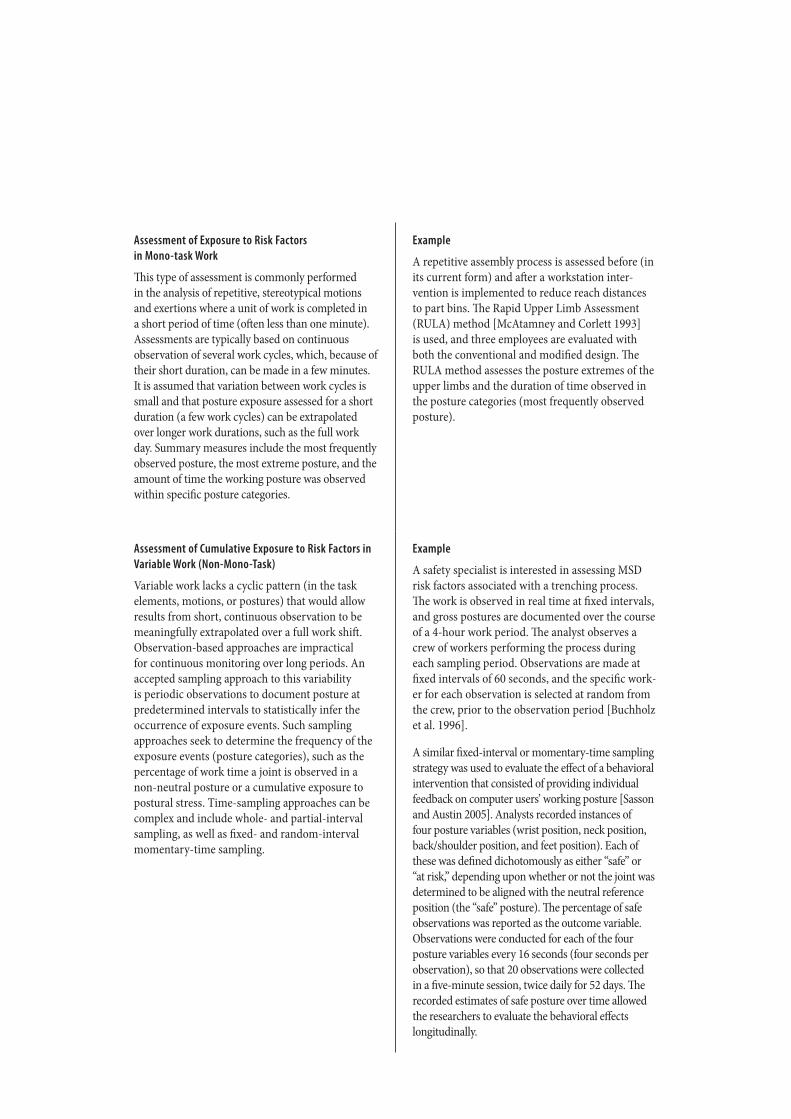
14 | Observation-Based Posture Assessment: Review of Current Practice and Recommendations for Improvement Observation-Based Posture Assessment: Review of Current Practice and Recommendations for Improvement | 15
Assessment of Exposure to Risk Factors in Mono-task Work
This type of assessment is commonly performed in the analysis of repetitive, stereotypical motions and exertions where a unit of work is completed in a short period of time (often less than one minute). Assessments are typically based on continuous observation of several work cycles, which, because of their short duration, can be made in a few minutes. It is assumed that variation between work cycles is small and that posture exposure assessed for a short duration (a few work cycles) can be extrapolated over longer work durations, such as the full work day. Summary measures include the most frequently observed posture, the most extreme posture, and the amount of time the working posture was observed within specific posture categories.
Example
A repetitive assembly process is assessed before (in its current form) and after a workstation inter-vention is implemented to reduce reach distances to part bins. The Rapid Upper Limb Assessment (RULA) method [McAtamney and Corlett 1993] is used, and three employees are evaluated with both the conventional and modified design. The RULA method assesses the posture extremes of the upper limbs and the duration of time observed in the posture categories (most frequently observed posture).
Assessment of Cumulative Exposure to Risk Factors in Variable Work (Non-Mono-Task)
Variable work lacks a cyclic pattern (in the task elements, motions, or postures) that would allow results from short, continuous observation to be meaningfully extrapolated over a full work shift. Observation-based approaches are impractical for continuous monitoring over long periods. An accepted sampling approach to this variability is periodic observations to document posture at predetermined intervals to statistically infer the occurrence of exposure events. Such sampling approaches seek to determine the frequency of the exposure events (posture categories), such as the percentage of work time a joint is observed in a non-neutral posture or a cumulative exposure to postural stress. Time-sampling approaches can be complex and include whole- and partial-interval sampling, as well as fixed- and random-interval momentary-time sampling.
Example
A safety specialist is interested in assessing MSD risk factors associated with a trenching process. The work is observed in real time at fixed intervals, and gross postures are documented over the course of a 4-hour work period. The analyst observes a crew of workers performing the process during each sampling period. Observations are made at fixed intervals of 60 seconds, and the specific work-er for each observation is selected at random from the crew, prior to the observation period [Buchholz et al. 1996].
A similar fixed-interval or momentary-time sampling strategy was used to evaluate the effect of a behavioral intervention that consisted of providing individual feedback on computer users’ working posture [Sasson and Austin 2005]. Analysts recorded instances of four posture variables (wrist position, neck position, back/shoulder position, and feet position). Each of these was defined dichotomously as either “safe” or “at risk,” depending upon whether or not the joint was determined to be aligned with the neutral reference position (the “safe” posture). The percentage of safe observations was reported as the outcome variable. Observations were conducted for each of the four posture variables every 16 seconds (four seconds per observation), so that 20 observations were collected in a five-minute session, twice daily for 52 days. The recorded estimates of safe posture over time allowed the researchers to evaluate the behavioral effects longitudinally.
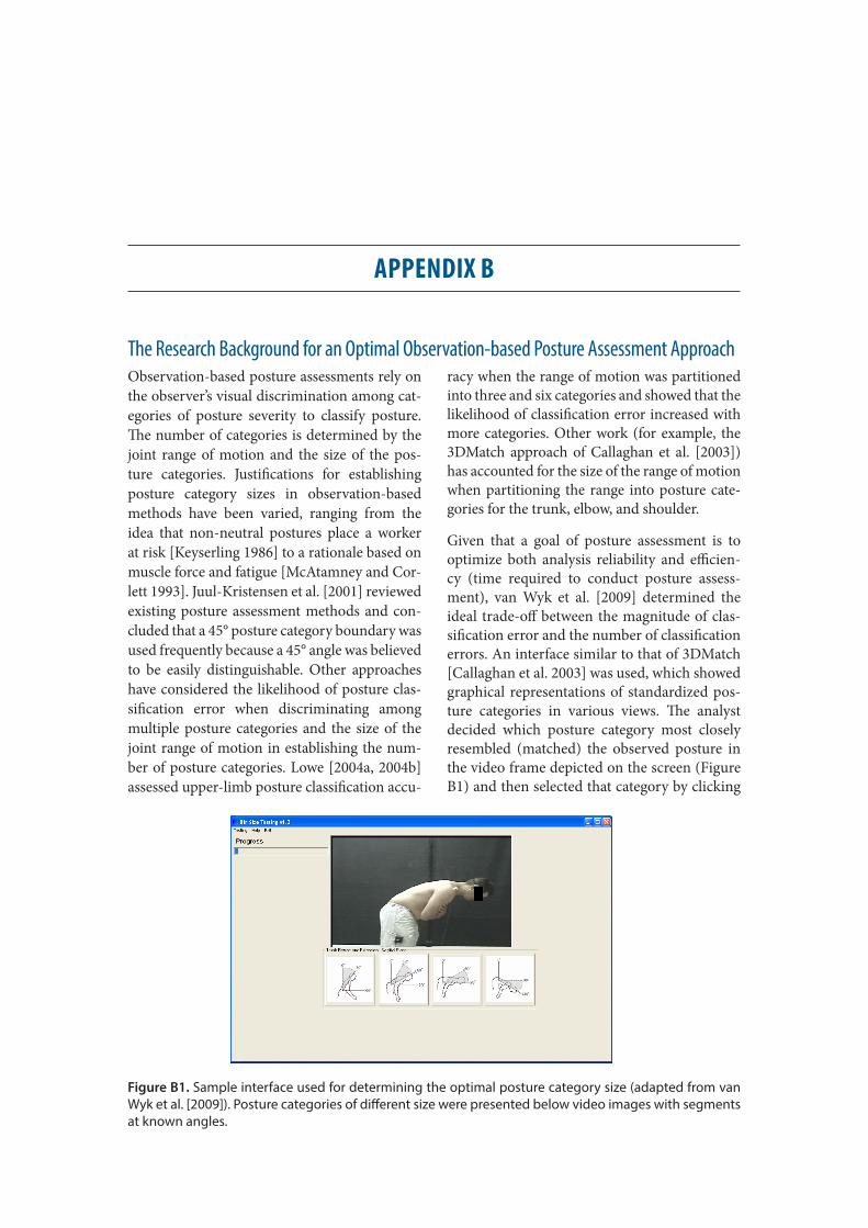
14 | Observation-Based Posture Assessment: Review of Current Practice and Recommendations for Improvement Observation-Based Posture Assessment: Review of Current Practice and Recommendations for Improvement | 15
APPENDIX B
The Research Background for an Optimal Observation-based Posture Assessment ApproachObservation-based posture assessments rely on the observer’s visual discrimination among cat-egories of posture severity to classify posture. The number of categories is determined by the joint range of motion and the size of the pos-ture categories. Justifications for establishing posture category sizes in observation-based methods have been varied, ranging from the idea that non-neutral postures place a worker at risk [Keyserling 1986] to a rationale based on muscle force and fatigue [McAtamney and Cor-lett 1993]. Juul-Kristensen et al. [2001] reviewed existing posture assessment methods and con-cluded that a 45° posture category boundary was used frequently because a 45° angle was believed to be easily distinguishable. Other approaches have considered the likelihood of posture clas-sification error when discriminating among multiple posture categories and the size of the joint range of motion in establishing the num-ber of posture categories. Lowe [2004a, 2004b] assessed upper-limb posture classification accu-
racy when the range of motion was partitioned into three and six categories and showed that the likelihood of classification error increased with more categories. Other work (for example, the 3DMatch approach of Callaghan et al. [2003]) has accounted for the size of the range of motion when partitioning the range into posture cate-gories for the trunk, elbow, and shoulder.
Given that a goal of posture assessment is to optimize both analysis reliability and efficien-cy (time required to conduct posture assess-ment), van Wyk et al. [2009] determined the ideal trade-off between the magnitude of clas-sification error and the number of classification errors. An interface similar to that of 3DMatch [Callaghan et al. 2003] was used, which showed graphical representations of standardized pos-ture categories in various views. The analyst decided which posture category most closely resembled (matched) the observed posture in the video frame depicted on the screen (Figure B1) and then selected that category by clicking
Figure B1. Sample interface used for determining the optimal posture category size (adapted from van Wyk et al. [2009]). Posture categories of different size were presented below video images with segments at known angles.

16 | Observation-Based Posture Assessment: Review of Current Practice and Recommendations for Improvement
on it with a mouse. The same video images were randomly shown to participants on the inter-face above five different sizes of posture cate-gories, ranging from a 10° category size (more categories in the classification) up to a 75° cate-gory size (fewer categories in the classification). The number of posture classification errors, the magnitude of error, and the decision time tak-en to make each posture selection were record-ed. The number of errors represented a simple count of how many errors were made. The mag-nitude of the error was the number of degrees difference between the middle of the measured (true) posture category and the middle of the category selected by the observer.
Two curves were plotted as a function of the size of the posture categories in the scale. One curve represented the magnitude of the errors and the other the number of errors. The point of inter-section of the two curves was identified (Figure B2) for postures of the trunk (flexion/extension and lateral bend), shoulder (flexion/extension and abduction/adduction), and elbow (flexion/extension). Selecting a posture category size
larger than the intersection point resulted in fewer posture classification errors but a higher magnitude of classification error. Conversely, selecting a posture category smaller than the intersection point reduced the magnitude of error but significantly increased the number of posture misclassifications. An example of this is seen in Figure B2, in which the optimal posture category size for shoulder abduction was de-termined to be 30°. This information was used to establish the optimal posture category sizes shown in Figure 2.
The proximity of a postural joint angle in re-lation to the posture category boundary also has a significant impact on the analyst’s ability to discriminate between adjacent posture cate-gories. When an observed posture is closer to (that is, within 2°–4° of) a boundary between categories, decision time is increased by 7% and the posture is more likely to be classified incor-rectly than when the posture is in the middle of the posture category [Andrews et al. 2008a, 2008b; Weir et al. 2011]. Implicit in this type of posture classification system is a trade-off
Figure B2. An example of the trade-off between magnitude of posture classification error and number of errors. The results depicted here are for shoulder abduction [van Wyk et al. 2009].
Observation-Based Posture Assessment: Review of Current Practice and Recommendations for Improvement | 17
between decision-making time and accuracy of classification. In order to improve the probabil-ity of correct posture classification and reduce decision-making time, the posture categories need to be relatively large, with few boundar-ies. However, increasing the size of the posture category reduces the resolution with which a posture can be identified. This would impact the output of any biomechanical model that is used to predict joint or segment loads on the basis of the specific posture input [Andrews et al. 2008a].
Wrist postures of concern as risk factors for mus-culoskeletal disorders (MSDs) are non-neutral flexion/extension and radial/ulnar deviation. Posture of the forearm in pronation/supination (twist of the forearm about the long bones) is also observed in many job assessment methods. Optimal posture category sizes for the wrist and forearm have not been determined in the same experimental manner as those in Figure 2 for the trunk, shoulder, and elbow. However, it is reasonable to believe that the selection of posture categories for the wrist and forearm can be guided by the same trade-off between the number of errors and the size of a resulting error in the posture classification. An import-ant consideration is the smaller size of the hand and forearm, which are observed in estimating wrist joint posture, and the narrower range of motion of this joint. The range of motion of the wrist from full flexion to full extension is approximately 150°. However, in radial/ulnar deviation, the range of motion of the wrist is much smaller, with ulnar deviation accounting for only about 30° of available motion (radial deviation is approximately 20°). A larger num-ber of posture classification errors should be ex-pected if one attempts to classify wrist postures with a precision that is equal (in number of pos-ture categories) to classifications of larger joints such as the elbow or shoulder [Lowe 2004b]. Visually discriminating among multiple levels of wrist radial/ulnar deviation categories is like-ly to result in even more errors than with larger joints because of the difficulty of the task.
Assessments of MSD risk factors, including the assessment of posture, should have high internal and external validity [Kilbom 1994]. Internal validity refers to the degree of agree-ment between the observation-based measures of risk factors and reference standards for these risk factors. The studies described above have more firmly established expectations for inter-nal validity, and it is largely this work on which the present emerging practice is based. Exter-nal validity refers to how strongly the analysis method results predict risk of MSDs. Knowl-edge of the relationship between physical risk factors (including working posture) and MSD risk continues to be advanced through epidemi-ological studies of workplace injury prevalence and mechanistic studies of tissue response to physical loads. A complete review of evidence related to the relationship between physical risk factors and MSDs is beyond the scope of this document (for complete reviews see NIOSH [1997] and NRC/IOM [2001]). The approach described in Section 3 of this document is consistent with existing evidence related to the external validity of MSD risk prediction. For example, more generally, it is known that trunk posture affects biomechanical forces and moments about the lumbar spine and the acti-vation of muscle tissue required to support and stabilize the spine in response to these external loads. Increasing exposure to flexion, lateral bend, and axial rotation of the spine increases risk for back injury. It is accepted that shoulder postures in which the arm is elevated create the potential for impingement in the subacromial and thoracic outlet spaces [Flatow et al. 1994] and place stresses on musculo-tendinous and joint capsule and ligament structures. Increas-ing arm elevation increases risk for impinge-ment-related and rotator cuff injury.
More specific posture categories that validly predict MSD risk across diverse work situ-ations, and in combination with other risk factors, are difficult to establish. For exam-ple, there is some evidence that MSD out-comes may be more sensitive to non-neutral
18 | Observation-Based Posture Assessment: Review of Current Practice and Recommendations for Improvement Observation-Based Posture Assessment: Review of Current Practice and Recommendations for Improvement | 19
posture than could be detected in the present approach to categorizing posture. For exam-ple, an epidemiological study by Punnett et al. [1991] adopted an a priori neutral cate-gory of 0° to 20° trunk flexion and showed increased injury risk with trunk postures exceeding 20°. This was demonstrated by calculating an odds ratio for the likelihood of injury when trunk flexion posture is less than 20° versus greater than 20°. The meth-
od presented in this document categorizes 0° to 30° as the neutral trunk flexion cate-gory, not because trunk postures less than 30° are necessarily of no risk but, rather, be-cause trunk flexion posture is more reliably classified by observation with the 30° range. An observation-based posture assessment method must consider both internal and ex-ternal validity of the posture classification (measurement).

“This course was developed from the public domain document: Practical Demonstrations of
Ergonomic Principles and Observation- Based Posture Assessment: Review of Current Practice
and Recommendations for Improvement– Department of Health and Human Services, Centers for
Disease Control and Prevention (CDC), National Institute for Occupational Safety and Health (NIOSH).”