estimation of cooling requirement of magnets in the multi cusp plasma device
TRANSCRIPT

IJRET: International Journal of Research in Engineering and Technology eISSN: 2319-1163 | pISSN: 2321-7308
_______________________________________________________________________________________
Volume: 04 Issue: 10 | OCT-2015, Available @ http://www.ijret.org 268
ESTIMATION OF COOLING REQUIREMENT OF MAGNETS IN THE
MULTI-CUSP PLASMA DEVICE
Nilesh Dama1, N. Ramasubramanian
2
1 Student, Mechanical Engineering, K. J. Somaiya College of Engineering, Mumbai, Maharashtra, India,
[email protected] 2 Scientist, Basic Sciences, Institute for Plasma Research, Gandhinagar, Gujarat, India
Abstract The need for energy generation from clean sources like nuclear fusion has given rise to increased research in the Plasma and its
characteristic properties. Multi-cusp Plasma Device installed at the IPR is one of the device used to study the plasma
characteristics wherein quiescent plasma is generated. An optimized design of water cooling system is necessary to ensure the
removal of heat losses and keep the electromagnets of the plasma device under the safe operating conditions of temperature and
thermal stresses by passage of flow of water, thereby increasing the life cycle of the device. The project focuses on the fluid flow
analysis for the heat transfer of generated heat in the magnet due to the continuous supply of electricity. The aim of this project is
to determine the performance and working attributes of the cooling system used. The design and evaluation of the cooling system
are executed on the basis of analytical calculations and actual experimentation work on the device.
Key Words: Chiller requirement, cooling requirement, electromagnet cooling, fluid flow analysis, Multi-cusp plasma
device, pressure drop, pump requirement, water cooling.
--------------------------------------------------------------------***----------------------------------------------------------------------
1. INTRODUCTION
The basic aim of Multi-Cusp Plasma Device is to confine
contact ionized (tungsten surface) cesium ions in a multi-
line cusp magnetic field and do its characterization. The
expected result of this plasma device is the generation of a
'text book' like ideal plasma, with Te ~ Ti, really quiescent,
with only 'natural' fluctuations [1]. The device would be
used to identify the real thermodynamic fluctuations and its
sources. The plasma generated would then be disturbed with
energy and particles and will be used to study the linear and
non-linear evolving phenomena of the plasma. The problem
arises due to drift of low frequency electrostatic waves
which propagates perpendicular to direction of B and dn.
The solution is provided by Cusp fields which produce B~0
in the centre. Vacuum chamber, Magnet assembly, hot
cathode ionizer, cesium vapor oven and probe diagnostics
are the major subsystems of this Multi-cusp Plasma Device.
This paper basically focuses on the Magnet part of the
device. Electromagnet with high Curie temperature soft-core
material is required for the Plasma device.
An electromagnet is a type of magnet in which the
magnetic field is produced by an electric current. The
magnetic field disappears when the current is turned off.
Electromagnets usually consist of a large number of closely
spaced turns of wire that create the magnetic field. The wire
turns are often wound around a magnetic core made from a
ferromagnetic material such as iron; the magnetic core
concentrates the magnetic flux and makes a more powerful
magnet. Electromagnets are made with Vacoflux-50 (alloy
of iron 50% and cobalt 50%) core material and copper pipes
are used as winding for water cooling. The main advantage
of an electromagnet over a permanent magnet is that the
magnetic field can be quickly changed by controlling the
amount of electric current in the winding. However, unlike a
permanent magnet that needs no power, an electromagnet
requires a continuous supply of current to maintain the
magnetic field. This continuous supply of current may
overheat the magnet. The electrical power which is
dissipated in the coils has to be removed from the magnets
otherwise overheating can seriously damage the coil
insulation and cause short circuits between the coil
conductor and the surrounding equipment which is usually
on ground potential. Therefore, a cooling arrangement is a
must for the electromagnet. The driving force for the
transfer of heat is the difference in temperature between the
two media. Coils that are pulsed infrequently for short
periods may not need to be cooled. The given report briefs
about the available types of cooling and it gives a proper
explanation for selection of particular type of cooling
system. It provides a detailed explanation about the
apparatus and the equipment required to perform a
successful experiment to determine the important
parameters for the cooling arrangement. So, the problem is
basically a thermo hydraulics problem. The velocity of the
flowing water should be sufficiently large enough(less than
5m/s) to ensure a turbulent flow but low enough to avoid
erosion and vibration. The experiment focuses on finding
values of water cooling system’s parameters like max flow
rate of water required to maintain magnet at room
temperature, pressure drop, temperature difference of inlet
and outlet water, water quality to be used, etc. using
theoretical calculations and by validating it with
experimental results.

IJRET: International Journal of Research in Engineering and Technology eISSN: 2319-1163 | pISSN: 2321-7308
_______________________________________________________________________________________
Volume: 04 Issue: 10 | OCT-2015, Available @ http://www.ijret.org 269
2. TYPES OF COOLING ARRANGEMENT
As per Zickler T, basically there are two types of cooling
methods to cool the magnet [2].
2.1. Air Cooling
It is also referred to as dry cooling. Air cooling by natural
convention is suitable only for low currents and low current
densities of up to 2A/mm2. Thus it would limit the use of
magnet to a moderate value field strength which is not at all
desirable
2.2. Water Cooling
Water cooling is also known as wet cooling. Direct and
indirect cooling are the two methods of water cooling. The
latter is of minor importance and rarely used, although it has
the advantage that normal tap water can be used as a
coolant, which does not require cooling plants with water
treatment for the supply of demineralized water. In the
absence of such infrastructure, indirect cooling should be
considered as a possible alternative, even though it implies a
more complex coil design.
The current density in direct water cooled coils can be
typically as high as 10A/mm2. It is a good compromise
assuring a high level of reliability during operation and
compact coil layout. Although current densities of 80A/mm2
can be attained for specific applications, it is not
recommended for standard magnets because the reliability
and lifetime of the coils is significantly reduced. High
currents require a sophisticated cooling circuit design with
prevention that high velocity of flowing water to carry away
the heat losses does not corrode or erode away the material
through which the water is flowing. Standard water cooled
coils are wound from rectangular or square, copper or
aluminium, conductor with a centre cooling duct for
demineralized water Since, water quality is essential for the
performance and reliability of the coil, the following typical
water properties should be guaranteed [3]:
Water resistivity higher than 5*106Ω.cm
pH value between 6 and 6.5
Dissolved oxygen below 0.1ppm
Since, in our system we have to pass a current of about
160A through the magnet coils for a long duration, it can be
easily made out that air cooling won’t suffice the need and
water cooling has to be used.
Once through cooling system, Open recirculating system
and closed recirculating system are the different types of
available water cooling arrangements.
In our Multi-cusp Plasma Device, direct water cooling is
used. The heated water after taking heat losses from the
magnet passes into the chiller (cooler) and the same water
after being cooled in the chiller is reused again to cool the
magnet. It is thus Open recirculating system where there is
no evaporation of the water because the chiller lid is closed
and thus there are no treatment related problems.
3. EXPERIMENTAL SETUP
There are 6 magnets at 20cm radius installed on the Multi-
cusp Plasma Device. The experiment was initially carried
out on 1 magnet and the results were obtained for 6 magnets
by assuming that they will show same characteristic
behaviour. Each magnet has a double pancake coil winding.
It has 8 pancakes (coils). Each pancake winding has 5 turns
in 1 direction (say clockwise) and 5 turns in other direction,
thereby accounting to a total of N=10 turns. At the centre of
the magnet is a soft core material called Vacoflux 50. The
purpose of the core material is just to shape the magnet field
generated, it doesn’t play any role in increasing the strength
of the generated magnetic field. This profiling is done to
reduce the edge saturation effects. The conductor coil is
made of copper material. Coil basically has elliptical kind
hollow conductor profile for carrying water to cool the coil.
Insulation is provided to prevent short-circuit or any
accident. Leads are provided on each coil winding for
applying current. Leads are all connected with screws to
connect coils in series electrically. Hydraulically, there are 2
available outlet pipes (bore in the copper conductor coil is
referred to as the pipe) in each pancake winding. So in total
we have 16 pipes for water flow. Cooled water enters into
these pipes after the chilled (cooler) water is pumped by the
pump. A header is provided at the top which distributes the
entire pressurized flow of cooling water into 8 small
different pipes which enter into each coil winding of the
magnet as the inlet. Similarly, 8 outlets of the coils of a
magnet are again input to another header called O/P header
from which a single pipe then goes to the cooler carrying
along heated water in it. PU pipes are used to connect
magnet coil pipes, with the inlet and outlet pipes connected
to the header. Valves are provided just near the inlet and
outlet of the magnet coil pipe to control the flow of water as
required. A DC power supply is used to provide current of
up to 160A to the magnet. A single wire has the current
capacity of 50A, so 3 wires were used to connect the
terminals of the power supply and magnet current leads. The
temperature of the cold water and the outlet heated water is
measured using a thermocouple connected to digital
multimeter (DMM). The mass of the water flowing through
magnet is estimated by using a stop watch and measuring
beaker arrangement. The specific characteristic values for
water were taken from NIST website [4], [5]. Various
properties, designs, technical data were obtained from [6] and the website was also used for calculations along with
Matlab, Excel software. [7] gives various steps to design the
cooling system.
Fig -1a: Magnet Assembly b) Pipes of magnet

IJRET: International Journal of Research in Engineering and Technology eISSN: 2319-1163 | pISSN: 2321-7308
_______________________________________________________________________________________
Volume: 04 Issue: 10 | OCT-2015, Available @ http://www.ijret.org 270
Fig -2: Hollow conductor pipe profile for coolant flow
Fig -3: Multi-cusp Plasma Device
Fig -4: Magnets and vacuum chamber
4. POSSIBLE METHODS TO CARRY OUT
EXPERIMENT
4.1. Calculations by finding pressure drop (Δp):
Heat loss is equal to enthalpy change of inlet and outlet.
Enthalpy is a function of pressure and temperature. So if we
know inlet and outlet pressure and temperature, we can
perform the experiment and optimize the cooling
requirement of the system. Pressure change can be measured
using a normal dial pressure gauge at inlet and outlet find
out Δp. As the pressure drop is related to the velocity of the
flow, this pressure drop will in turn give the velocity of the
flowing water. Flow rate m can be calculated from the
velocity thus obtained. This flow rate can also be used to
find out heat load (heat loss) on the magnet. In this
experiment, mass flow of the water m should be changed
and different readings should be noted accordingly for a
given current flow. Further change the current and repeat the
above procedure.
Δp can also be found out using a Differential pressure
gauge or a U-tube Manometer.
4.2. Calculations by Finding Mass Flow Rate (m):
A flowmeter or rotameter would directly give the flow rate
of water flowing through the magnet. This flow rate should
then be compared with theoretically required mass flow rate
of water. Using formulas we can find out other important
parameters. Here, the readings should be taken for different
values of ΔT by adjusting the flow for a particular ΔT and
noting that flow rate reading perform other calculations for
cooling system design
4.3. Hydraulic and Electrical connections:
There are n number of ways to hydraulically connect the
given magnet pipes to ensure the cooling of the magnet. We
can test each single coil’s water requirement by passing
different current. Various parallel and series combination of
pipes can be done for the efficient cooling.
The experiments were performed for:
Only 1st coil with a current passage of 100A
1,2,3 coils connected in parallel and a current passage
of 100A
1,3,5,7 coils connected in parallel and a current of
100A is passed
4 parallel groups of 2 coils in series (i.e 1,2 + 3,4 + 5,6
+ 7,8) . Here outlet of 1 is connected to the inlet of 2,
Outlet of 3 to the inlet of 4, and so on. Thus effectively
we get 4 inlet pipes and 4 outlet pipes in this hydraulic
arrangement. The readings here were taken for 100A
as well as 150A
Last option is to connect all 8 coils in a parallel
manner. This would also ensure proper cooling as
water flows through each pipe. But the pressure drop in
this case will be low as there will be resistance of only
1 coil. Also there would be requirement of more piping
in this case and to control 8 inlet and 8 outlet valves of
1 magnet would be a difficult task
4.4. Experiment Procedure Overview:
[1]. Calculate heat loss (heat load)
[2]. Calculate flow requirement
[3]. Find flow velocity
[4]. Find out pressure drop
[5]. Calculate pump capacity required
[6]. Chiller required
5. OBSERVATIONS
From the tests it was found out that making 4 parallel groups
of 2 coils in series was the best combination for cooling the
magnet with minimum water requirement. Passing the water
through 4 alternate coils (1,3,5,7) is also not advisable as the
water here wouldn’t cool the coil numbers (2,4,6,8) and thus
it would not result in the proper cooling of the magnet.

IJRET: International Journal of Research in Engineering and Technology eISSN: 2319-1163 | pISSN: 2321-7308
_______________________________________________________________________________________
Volume: 04 Issue: 10 | OCT-2015, Available @ http://www.ijret.org 271
Table -1: Parameter values
Resistivity of copper
pipe 1.68 × 10⁻⁸ Ω.m
Dimension of water
carrying region of pipe w, h 5.2mm, 3.2mm
Hydraulic diameter Dh 3.96mm Area for water flow Af 16.64mm2
Outer area of pipe Ao 59.84mm2
Area of current carrying
region A=(Ao-Af) 43.2mm2
Specific heat of water
4.187kJ/kg.K
Density of water 996.69 kg/m3
Viscosity of water at
20 ,2 bar 10.016×10⁻⁴ Pa.s
: length of pipe in consideration
: mass flow rate of water
:rise in temperature=outlet temperature–inlet temperature
: velocity of water
: Reynolds number
f: friction factor
Table -2: Pump and cooler specifications
Pump Specifications Cooler specifications
Kirloskar Brothers Blue Star
TYPE : KDS- 225+ POWER SUPPLY:AC 1
PHASE,230V,50Hz
Sr.NUMBER:ATABXF0290 CURRENT :7A F.L.A
SIZE : 50×40 I/P kW: 2 POWER CONUMPTION
: 1550 Watts
HEAD : 22.0m REFRIGERANT:R-22
950 grams
HEAD RANGE: 15 TO 25m STORAGE: 150 L
LPS:3.1 rpm:2840 COOLING CAPACITY :
150 ltr/hours
CAPACITY RANGE : lps
4.1-2.2
KW/HP : 1.5/2 ;
OVERALL OFF : 48 %
DUTY S1 INDUCTION
MOTOR 50HZ 1 PHASE
:230 VAC
Table -3: Details of magnet and its rated values
No of magnets 6
Total no of pancake coil windings 8 pancake double
winding
Number of turns in each pancake N 10 (5 + 5)
Max current to be passed in each
magnet and time duration
160A and continuous
supply
Max allowable temperature 150
Max pressure of water allowed
through inlet
10 bar
Operating pressure 2.2 bar (22m Head)
Water used DM water
Fig -5: Temperature reading shown by DMM
Fig -6: Hydraulic connections of a magnet
Fig -7: Layout diagram of project setup
PU Pipe

IJRET: International Journal of Research in Engineering and Technology eISSN: 2319-1163 | pISSN: 2321-7308
_______________________________________________________________________________________
Volume: 04 Issue: 10 | OCT-2015, Available @ http://www.ijret.org 272
Table -4: For Current I=100.3A, Voltage V=9.6V
Water
Quantity
Outlet
Temper
ature
(in )
Inlet
Temper
ature
(in )
ΔT
(in
ml)
(in
kg/s)
(in
lpm)
1770 0.059 3.54 30 23.2 6.8
1820 0.0606 3.64 29.8 21.7 8.1
1840 0.0613 3.68 29.7 22.4 7.3
1800 0.06 3.6 29.6 22.4 7.2
1820 0.0606 3.64 29.5 21.8 7.7
Table -5: For Current I=150.1A, Voltage V=14.4V
Water
Quantity
Outlet
Temper
ature
(in )
Inlet
Temperat
ure
(in )
ΔT
(in
ml)
(in
kg/s)
(in
lpm)
1800 0.06 3.6 32.7 21.2 11.5
1850 0.0616 3.7 32.9 22.1 10.8
1850 0.0616 3.7 33 21.7 11.3
1850 0.0616 3.7 32.9 21.6 11.3
1870 0.0623 3.74 33 21.9 11.1
1830 0.061 3.66 33.2 22.2 11.0
6. CALCULATIONS
Theoretical calculations for I=100.3A, V= 9.6V for 1
magnet
Let us denote grouping of 1st and 2
nd coil in series as 1st
connection
Similarly 3rd
-4th
coil in series represent 2 connection
Resistance of 1 coil,
(1)
R = (1.68 × 10-8
×30)/(43.2×10-6
) = 0.011667 Ω
R of 2 coils = R1connection (2)
R of 2 coils = 2×0.011667=0.023334Ω
Also, Resistance of 8 coils (4 connections),
Rseries=V/I (3)
Rseries = 9.6/100.3 = 0.0957 Ω
R1connection =Rseries/Total connections (4)
R1connection = 0.0957/4=0.0239282 Ω
Heat load = I2 .R1connection (5)
Heat load = 100.3 * 0.02334 = 234.8025006W
I/P Power = VI for 8 coils
= [(V1 +V2)+(V3+V4)+(V5+V6)+(V7+V8)] *I
= [V1connection+V2connection+V3connecton
+V4connection]* I
= 9.6 * 100.3 for 8 coils
= 962.88 Watt
Water required:
Heat load / Heat loss = m.Cp.ΔT (6)
234.8025006 = m × 4.187 × (29.72-22.3)
m = 7.5578079 × 10⁻³
kg/s
m = 0.045346847 lpm or kg/min
For 1 connection ,
m = ρ.Af.v (7)
7.5578079 × 10-3
= 996.69 × 1.64× 10-5
× v
v = 0.45570356 m/s
(8)
Re = (996.69×0.45570356×3.96×10-3
)/(10.016×10-4
)
= 1795.7397
f=64/Re (9)
f= 64/1795.7397 = 0.0356399 (considering laminar flow)
(10)
Δp= (0.0356399*60*996.69*0.45570356) / (2*3.96*10-3
)
=1.2263235bar
Δp will be same for all the four connections, i.e, same for
the entire magnet
Pump Capacity:-
Pump capacity required for proper water flow in 1 magnet:
M=4× m (11)
M = 0.0302312316 kg/s = 1.81387389 lpm= mass flow rate
for 1 magnet
Pump capacity to provide water flow in 6 magnets:
Mtotal = 6×M (12)
Mtotal = 10.88324334 lpm= mass flow rate for all 6 magnets
Chiller Capacity:-
Chiller capacity is ideally taken as 30% more than heat loss
So, for 1 connection = 1.3 × Heat loss = 1.3 ×
234.8025006= 305.24325W
For 1 magnet = 4 × 1 connection = 1220.73003W
For 6 magnets=4 × 1 magnet = 7325.838W
Thus, Chiller should be able to remove 7325.838W of heat
from the total hot water coming out of 6magnets to make it
cool again for entry to inlet of magnet
7. GRAPHS
Chart -1: Δp vs M for I=100A
IJRET: International Journal of Research in Engineering and Technology eISSN: 2319-1163 | pISSN: 2321-7308
_______________________________________________________________________________________
Volume: 04 Issue: 10 | OCT-2015, Available @ http://www.ijret.org 273
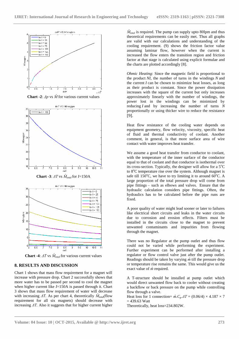
Chart -2: Δp vs M for various current values
Chart -3: ΔT vs Mtotal for I=150A
Chart -4: ΔT vs Mtotal for various current values
8. RESULTS AND DISCUSSION
Chart 1 shows that mass flow requirement for a magnet will
increase with pressure drop. Chart 2 successfully shows that
more water has to be passed per second to cool the magnet
when higher current like I=150A is passed through it. Chart
3 shows that mass flow requirement of water will decrease
with increasing ΔT. As per chart 4, theoretically Mtotal(flow
requirement for all six magnets) should decrease with
increasing ΔT. Also it suggests that for higher current higher
Mtotal is required. The pump can supply upto 80lpm and thus
theoretical requirements can be easily met. Thus all graphs
are valid with our calculations and understanding of the
cooling requirement. (9) shows the friction factor value
assuming laminar flow, however when the current is
increased the flow enters the transition region and friction
factor at that stage is calculated using explicit formulae and
the charts are plotted accordingly [8].
Ohmic Heating: Since the magnetic field is proportional to
the product NI, the number of turns in the windings N and
the current I can be chosen to minimize heat losses, as long
as their product is constant. Since the power dissipation
increases with the square of the current but only increases
approximately linearly with the number of windings, the
power lost in the windings can be minimized by
reducing I and by increasing the number of turns N
proportionally or using thicker wire to reduce the resistance
[9].
Heat flow resistance of the cooling water depends on
equipment geometry, flow velocity, viscosity, specific heat
of fluid and thermal conductivity of coolant. Another
comment, in general, is that more surface area of wire
contact with water improves heat transfer.
We assume a good heat transfer from conductor to coolant,
with the temperature of the inner surface of the conductor
equal to that of coolant and that conductor is isothermal over
its cross-section. Typically, the designer will allow for a 5oC
to 8oC temperature rise over the system. Although magnet is
safe till 150oC, we have to try limiting it to around 60
oC. A
large proportion of the total pressure drop will come from
pipe fittings – such as elbows and valves. Ensure that the
hydraulic calculation considers pipe fittings. Often, the
hydraulics has to be calculated before the pipe runs are
fixed.
A poor quality of water might lead sooner or later to failures
like electrical short circuits and leaks in the water circuits
due to corrosion and erosion effects. Filters must be
installed in the circuits close to the magnet to prevent
unwanted contaminants and impurities from flowing
through the magnet.
There was no Regulator at the pump outlet and thus flow
could not be varied while performing the experiment.
Further experiment can be performed after installing a
regulator or flow control valve just after the pump outlet.
Readings should be taken by varying m till the pressure drop
or temperature rise remains the same. This would give us the
exact value of m required.
A T-structure should be installed at pump outlet which
would direct unwanted flow back to cooler without creating
a backflow or back pressure on the pump while controlling
flow through a valve.
Heat loss for 1 connection= m.Cp.ΔT = (0.06/4) × 4.187 × 7
= 439.63 Watt
Theoretically, heat loss=234.802W.

IJRET: International Journal of Research in Engineering and Technology eISSN: 2319-1163 | pISSN: 2321-7308
_______________________________________________________________________________________
Volume: 04 Issue: 10 | OCT-2015, Available @ http://www.ijret.org 274
This error in heat loss occurred as the temperature reading
was taken at the cooler inlet and cooler outlet. From the
graphs also it can be seen that if m increases, ΔT decreases.
Experimentally, mass flow rate was greater than theoretical
value, so ΔT has to decrease experimentally to around 4.5oC
from 7.5oC. This happened when readings were again taken
just near the magnet inlet and outlet.
Corrected experimental reading is
Heat loss for 1 connection= m.Cp.ΔT= (0.06/4) × 4.187 × 4.5
= 282.62W
282.62-234.802= 57.818W energy is the energy which is
gained from the surroundings and due to other unaccounted
losses. The readings should therefore be taken just near the
magnet inlet and outlet pipes.
Power of pump = ρ.g.Q.H (13)
Given pump is of 2 hp. Let us check whether 0.5 hp pump
KDS0510 with head of 10m would suffice the need from the
specifications available of the kirloskar pumps [10] Its capacity is 0.94*60=56.4lpm.With around 50%
efficiency it could provide upto 28lpm
This pump is sufficient. But to maintain a safeside we may
select 1HP pump
1. KDS116+ with head of 14 or 16m which will provide
3.62 , 3 lps
2. KDS 123+ with head of 14 or 16m
Fig -8: Kirloskar Pump Product catalogue
The observation table for arrangement 4 shows that the mass
flow rate of water is almost same for 100A as well as 150A.
That’s the reason why ΔT increased for 150A reading as the
mass flow was still the same. This mass flowing through the
magnet is almost 2 times more than required flow rate for
cooling. As per the calculations, laminar flow is sufficient
for cooling the magnet, however available mass flow rate
denotes just the start of turbulence region where heat
transfer coefficient is good and thus good cooling will be
provided.
Current cooler’s cooling capacity is of 150litres/hour. It was
enough to perform experiment for a single magnet. But for 6
magnets we need to have cooler which can remove
7.325838kW heat from water. So, for efficient performance
we would have to have a cooler with increased capacity.
150litres/hour = 0.04167kg/s
Suppose the cooler inlet temperature is 32 and we want
O/p to be 10 , i.e .ΔT =22
So, Q= m.Cp.ΔT=0.04167×4.187×22=3.83839kW.
1. We either have to bring a cooler of increased capacity
or
2. We have to compromise with cooling effect .ΔT of this
cooler, i.e we won’t get very cold water from cooler or
3. We would have to install 2 coolers of the same
capacity to provide the necessary result
9. CONCLUSION
The best hydraulic connection is parallel combination of 4
groups (each group has 2 consecutive coils in series)
The present pump is almost supplying 1.5-2times the flow
required for compensating heat loss and is thus of high
capacity. To prevent unnecessary energy wastage, following
light duty pumps are recommended:
[1]. KDS116+ with head of 14 or 16m which provides 3.6,
3 lps
[2]. KDS 123+ with head of 14 or 16m Cooler is required
to remove 7.326kW heat from water
[3]. We either have to bring a cooler of increased capacity
[4]. We have to compromise with cooling effect ΔT of this
cooler, i.e. we won’t get very cold water of around 10 oC from cooler
[5]. We would have to install 2 coolers of the same
capacity to provide the necessary cooling.
The amount of the cold water required depends on
equipment geometry, flow velocity, viscosity, and hydraulic
diameter, resistance to water flow, temperature rise, and
specific heat of fluid and thermal conductivity of coolant.
Also more surface area of wire contact with water due to
more number of coil turns (10 in 1 pancake winding)
improves heat transfer rate and thus improves the cooling of
the magnet.
The power lost in the windings can be minimized by
reducing the current I and increasing the number of
turns N proportionally, or using thicker wire to reduce the
resistance.
For 100A current, 10.88lpm water is required to cool all the
6 magnets by allowing a temperature rise of around 7.5oC.
Value of various characteristic parameters like flow rate of
water required to maintain magnet at room temperature,
pressure drop, temperature difference of inlet and outlet
water, were calculated using theoretical calculations and
were validated by comparing them with experimental
results.

IJRET: International Journal of Research in Engineering and Technology eISSN: 2319-1163 | pISSN: 2321-7308
_______________________________________________________________________________________
Volume: 04 Issue: 10 | OCT-2015, Available @ http://www.ijret.org 275
ACKNOWLEDGEMENT I wish to acknowledge and express my sincere thanks to Mr
Sudhir Sharma, Mr Yagnesh Trivedi, Mr. Krishan Kumar
Gotewal, Dr Vipul Tanna for their valuable guidance during
this work. Special thanks to Mr. Amit Patel and Ms.
Meenakshi Sharma who helped me in performing the
experimental work
REFERENCES
[1]. Bage A, Ramsubramanian N, Thermal Analysis of
Vacuum Chamber of Q-Machine, Advanced
Materials Manufacturing & Characterization, Vol 4,
Issue 1, 2014
[2]. Th. Zickler, Basic design and engineering of normal-
conducting, iron-dominated electromagnets, CERN
Accelerator School CAS 2009: Specialized Course
on Magnets, Bruges, 16-25 June 2009, CERN-2010-
004, pp. 65-102
[3]. G. E. Fischer, Iron dominated magnets, 4th
Summer
School on Particle Accelerators, Fermilab, Batavia,
IL, 1984, M. Dienes and M. Month (Eds.), AIP
Conference Proceedings 153(1987), pp. 1120-1227
[SLAC-PUB-3726(1985)]
[4]. National Institute of Standards and Technology (n. d)
http://webbook.nist.gov/chemistry/fluid/
[5]. E.W. Lemmon, M.O. McLinden and D.G. Friend,
"Thermophysical Properties of Fluid Systems"
in NIST Chemistry WebBook, NIST Standard
Reference Database Number 69, Eds. P.J. Linstrom
and W.G. Mallard, National Institute of Standards
and Technology, Gaithersburg MD, 20899,
http://webbook.nist.gov, (retrieved October 11,
2015).
[6]. Your Chemical Engineering portal, myChemE (n.d)
Retrieved from http://www.mycheme.com/ [7]. Design of cooling water system (2013, February 14)
Retrieved from http://www.mycheme.com/design-of-
cooling-water-systems/
[8]. Diniz, V. E. M. G. & Souza, P. A., Four explicit
formulae for friction factor calculations in pipe flow,
WIT Transactions on Ecology and the Environment,
125, pp. 369-380, 2009
[9]. Meyrath, Todd, Electromagnet Design Basics for
Cold Atom Experiments, Atom Optics Laboratory
Center for Nonlinear Dynamics, University of Texas
at Austin, 2003.
[10]. Kirloskar pumps (n. d) Retrieved from
http://www.kirloskarpumps.com/pdf/offerings/distrib
ution/Industry-Catalogue.pdf
[11]. Moore, Davis, Coplan Building Scientific Apparatus.
Perseus Books, 4th edition
BIOGRAPHIES
Nilesh Dama is currently a 4th
year
Mechanical engineering student studying
at K.J.Somaiya College of Engineering.
He has research interests in the field of
thermal sciences, cryogenics, and
renewable energy.
Dr. N. Ramasubramanian is Scientist
SE working in Basic Plasma Sciences
and is the Head of the Multi-cusp
plasma division at the Institute for
Plasma Research, Gandhinagar.