euler satcom waveform study outcomes - centre for wireless
TRANSCRIPT

FP7-Security EULER
Deliverable 5.4 – EULER Satcom waveform study outcomes Public 1/93
EULER
Deliverable 5.4
EULER Satcom waveform study outcomes
Version 1.0
Deliverable manager Contributors Checked by
Damiano Valletta (TEL) Damiano Valletta (TEL) Raul Dopico López (IND) Taj A. Sturman (AUK)
Damiano Valletta (TEL) Raul Dopico López (IND) Taj A. Sturman (AUK)

FP7-Security EULER
Deliverable 5.4 – EULER Satcom waveform study outcomes Public 2/93
Document Lifecycle Revision number
Date Contributor Evolution
0.1 1th of February, 2010 Damiano Valletta (TEL) Document creation
0.2 28th of February, 2011 Damiano Valletta (TEL)
Satellite network architecture definition, Analysis of OFDMA
Adaptation for SATCOM link
0.3 6th of April, 2011 Damiano Valletta (TEL)
Raul Dopico López (IND)
Addition of Preliminary analysis of EWF
adaptation to Satellite environments and
Simulation Assessment
0.4 31th of May, 2011 Raul Dopico López (IND)
Addition of EWF adaptation to Satellite
environments
0.5 17th of June, 2011 Raul Dopico López (IND)
EWF adaptation to Satellite environments
review based on Partners Comments
0.6 20th of June, 2011 Damiano Valletta (TEL) Document review, some
minor modifications
0.7 13th July, 2011 Taj Sturman (AUK) Document review, some
minor modifications
0.8 19th July, 2011 Raúl Dopico López (IND) Comments from EADS-
Astrium integrated in Chapter 5
0.9 20th July, 2011to 2nd
Aug 2011 Taj Sturman (AUK)
Augmented report with comments and enhanced
Chapter 9. 0.91 3rd Aug 2011 Taj Sturman (AUK) Enhancement of report
0.92 3rd Aug 2011 Damiano Valletta (TEL)
Comments from EADS-Astrium integrated in the Deliverable, some minor
modifications. 0.93 4th Aug 2011 Taj Sturman (AUK) Enhancement of report. 0.94 4th Aug 2011 Damiano Valletta (TEL) Enhancement of report. 0.95 18th Aug 2011 Taj Sturman (AUK) Enhancement of report. 0.96 31th Aug 2011 Damiano Valletta (TEL) Enhancement of report. 1.0 1th Sept 2011 Damiano Valletta (TEL) Enhancement of report.

FP7-Security EULER
Deliverable 5.4 – EULER Satcom waveform study outcomes Public 3/93
Table of Contents Document Lifecycle ................................................................................................................... 2
Table of Contents ....................................................................................................................... 3
Figure Index ............................................................................................................................... 4
Acknowledgements .................................................................................................................... 6
1 Document generalities........................................................................................................ 7 1.1 Scope .......................................................................................................................... 7 1.2 Acronyms ................................................................................................................... 8
2 Introduction ...................................................................................................................... 11
2.1.1 Satellite Network Architectural Solutions............................................................ 13
3 Satellite role in EULER architecture................................................................................ 15 3.1 Envisaged Scenarios................................................................................................. 16
3.1.1 Satellite connecting two or more IANs ................................................................ 16
3.1.2 Satellite connecting a IAN and a JAN..................................................................17
3.2 Satellite constraints .................................................................................................. 18 3.3 Supported services.................................................................................................... 18
4 OFDMA adaptation for SATCOM .................................................................................. 21 4.1 Technical analysis of OFDMA adaptation to SATCOM......................................... 23
4.1.1 Synchronization procedure................................................................................... 27 4.1.2 Ranging procedure ............................................................................................... 34
4.2 Summary .................................................................................................................. 36 5 EWF adaptation to Satellite environments....................................................................... 37
5.1 EWF Impact analysis for Satellite channels............................................................. 37
5.1.1 Impact on the physical layer................................................................................. 37 5.2 Impact on the Security Sublayer .............................................................................. 39 5.3 Impact on the Medium Access Control Layer. ........................................................ 40
5.4 Description of ESWF ............................................................................................... 42 5.4.1 Physical Layer ...................................................................................................... 42 5.4.2 Security Sublayer ................................................................................................. 44 5.4.3 MAC Layer .......................................................................................................... 51 5.4.4 ESWF Support Services ....................................................................................... 53
5.5 ESWF Requirements Specification.......................................................................... 56
5.5.1 Physical Layer ...................................................................................................... 56 5.5.2 Security Sublayer ................................................................................................. 56 5.5.3 MAC Layer .......................................................................................................... 57
6 Simulations Assessment................................................................................................... 59 6.1 System Description and Network Architecture........................................................ 59
6.2 GEO Satellite............................................................................................................ 60 6.3 European Coverage of satellite system .................................................................... 61
6.4 Transponder Bandwidth ........................................................................................... 61 6.5 Multiple Access techniques...................................................................................... 62
6.5.1 Demand Assignment Multiple Access ................................................................. 62
6.5.2 DVBS2-RCS for Mesh and Star networks........................................................... 63
6.5.3 OFDM-OFDMA................................................................................................... 63

FP7-Security EULER
Deliverable 5.4 – EULER Satcom waveform study outcomes Public 4/93
6.6 Coding Correction Techniques................................................................................. 67 6.7 Modulation Techniques............................................................................................ 68 6.8 Spectral Efficiency ................................................................................................... 69 6.9 Link Analysis Parameters......................................................................................... 69
6.9.1 Eb/N0, BER assumed for the analysis ................................................................. 69
6.9.2 System Parameters (Clear Sky)............................................................................ 70
6.9.3 Rain Losses .......................................................................................................... 71 6.10 Result Summary ....................................................................................................... 71
7 Additional Utilisation of the OFDM-OFDMA Technique .............................................. 79
7.1 CDM-CDMA over OFDM-OFDMA Applications.................................................. 79
8 Considerations on the use of OFDM-OFDMA Technology for Satellite Applications... 80 8.1 Considerations on the Application possibility .........................................................80
8.2 Some technological highlights ................................................................................. 80 8.3 Considerations on the Software Define Radio technology ...................................... 81
9 Recommendation for a future Satcom WF for P&GS...................................................... 83
9.1 Introduction .............................................................................................................. 83 9.2 Information Assurance in the EULER system ......................................................... 85
9.3 IA-based SATCOM with SDR................................................................................. 86
9.4 EULER SATCOM Solution..................................................................................... 88
9.5 Summary .................................................................................................................. 88 10 Conclusions ...................................................................................................................... 90 11 References ........................................................................................................................ 92
Figure Index Figure 1: Example of possible connection in various Area Network. .....................................16
Figure 2:Example of connection between two IANs through satellite. ................................... 17
Figure 3: Example of connection between one IAN and one JAN through satellite. .............. 17
Figure 4: General scheme for a mobile terminal connected to the earth station through the satellite. .................................................................................................................................... 18
Figure 5: Reference model for a Satellite System.................................................................... 26 Figure 6: Example of symbol structure for resource allocation. .............................................. 27 Figure 7: Example of symbol structure for resource allocation with high granularity for resources allocation. ................................................................................................................. 27
Figure 8: Potential effects of different differential delays in satellite channels on the frame synchronization at the user terminal......................................................................................... 28 Figure 9: Potential effects of different differential delays in satellite channels on the frame synchronization at the user terminal (D1<Dmean). .................................................................. 29 Figure 10: Potential effects of different differential delays in satellite channels on the frame synchronization at the user terminal (D2> Dmean). ................................................................. 29 Figure 11: Illustration of an uplink allocation for UT having propagation delay equal to the mean propagation delay. .......................................................................................................... 30 Figure 12: Illustration of an uplink allocation for UT having propagation delay less than the mean propagation delay. .......................................................................................................... 30 Figure 13: Illustration of an uplink allocation for UT having propagation delay greater than the mean propagation delay...................................................................................................... 30

FP7-Security EULER
Deliverable 5.4 – EULER Satcom waveform study outcomes Public 5/93
Figure 14: Uplink and downlink frame synchronization for UT having propagation delay equal to mean propagation delay (i.e 250 ms for GEO satellite). ............................................ 31 Figure 15: Uplink and downlink frame synchronization for UT with differential propagation delay of –x milliseconds relative to the mean propagation delay. A guard time of |2x| is provided at the end of the uplink subframe UL1 to avoid overlapping ...................................32
Figure 16: Uplink and downlink frame synchronization for UT with differential propagation delay of –x milliseconds relative to the mean propagation delay. A guard time of 2|x| ms is added at the beginning of the downlink subframe DL2 to avoid overlapping. ........................ 32
Figure 17: Uplink and downlink frame synchronization for UT with differential propagation delay of x milliseconds relative to the mean propagation delay. A guard time of 2x milliseconds is added at the end of the downlink subframe DL1 to avoid the overlapping with the uplink subframe UL1.......................................................................................................... 33 Figure 18: Uplink and downlink frame synchronization for UT with differential propagation delay of x milliseconds relative to the mean propagation delay. A guard time of 2|x| milliseconds is added at the beginning of the uplink subframe UL1 to avoid the overlapping................................................................................................................................................... 33
Figure 19: Example of allocation of subchannels /symbols to a ranging codeword................ 34
Figure 20: Ranging window used at a satellite /earth station................................................... 35 Figure 21: Illustration of ranging operations in a satellite system. .......................................... 36 Figure 22: ESWF deployed over a geosynchronous satellite and only a spot beam. A deployed system can include more spot beams. ...................................................................................... 37 Figure 23: Frame structure of 802.16....................................................................................... 42 Figure 24: The largest possible spot beam............................................................................... 42 Figure 25: HFDD: the Up sub-frame and Dw sub-frame must no overlap at the satellite consequently the SS must delay the Up sub-frame. In the figure UP subframes at different SSs are represented.......................................................................................................................... 43
Figure 26: Up and down sub-frames according to Figure 25 explanations ............................. 43
Figure 27: Framing structure of the ESWF.............................................................................. 44 Figure 28: Only the OFDM symbols that do not overlap in the BS are transmitted. These kinds of solutions were discarded since need a more in depth change in the EWF................. 44
Figure 29: Initial transmission and retransmission of ARQ blocks. ........................................ 52
Figure 30: Network Architecture with three types of links: Forward, Return and and one-to-one. ........................................................................................................................................... 60
Figure 31: EIRP Contours Ku band W2 satellite. ................................................................... 62 Figure 32:OFDM frequency Channel example. ....................................................................... 64 Figure 33:OFDMA Frame structure example according to IEEE 802.16 TDD mode............. 65
Figure 34: Eb/N0 for different modulation and correcting code schemes................................. 68
Figure 35: Summary results assuming OFDM-OFDMA filling one 72 MHz Transponder Rain considered on the Hub satellite up link (uppc included), on the satellite-Hub down link and on both up link and down link for VSAT with rain ...................................................................... 73 Figure 36: Summary Results assuming DVB-RCS carriers filling one 72 MHz Transponder (34% DVB 66% RCS). Rain considered on the Hub satellite up link (uppc included), on the satellite-Hub down link and on both up link and down link for VSAT with rain.................... 74
Figure 37: Forward link from Hub to VSAT including rain on the up link OFDM stream..... 75
Figure 38: Return link from VSAT to Hub including rain on the down link OFDMA streams................................................................................................................................................... 76
Figure 39:Forward link from Hub to VSAT including rain on the up link DVB stream......... 77
Figure 40: Return link from VSAT to Hub including rain on the down link RCS streams.... 78

FP7-Security EULER
Deliverable 5.4 – EULER Satcom waveform study outcomes Public 6/93
Figure 41: Combined use of the transponder as a generic VSAT service network and a sensor network..................................................................................................................................... 79
Figure 42: VSAT station using SDR technology. .................................................................... 82 Figure 43: TerreStar Coverage[10] .......................................................................................... 83 Figure 44: Example WiMAX to Blue-light Data base retrieval employing BLOS ................. 85
Figure 45: Conceptual “shelf” decomposition of a Secure SDR ............................................. 86
Figure 46: Example DVB Networking Image.......................................................................... 88
Acknowledgements ASTRIUM (UK) i.e. AUK would like to acknowledge the support offered by its colleagues in producing the deliverable T5.4(R) i.e.: Mark Bowyer, Andy Hoyle, Garry Matthews, Martin Moseley, David Pe ilow, Howard Sharp, Chris Staples and Michael Woodford.

FP7-Security EULER
Deliverable 5.4 – EULER Satcom waveform study outcomes Public 7/93
1 Document generalities
1.1 Scope The objectives of work package (WP) 5 are to design the Software Defined Radio (SDR) waveform and produce specifications for two high data rate waveforms (WFs) based on a common architecture provided by ESRA: the terrestrial WF (WiMAX-derived) and satellite WF. The first one is also integrated in different platforms within WP4 objectives, while the second one has a limited ambition and proposes only some features for satellite link characteristics. Main inputs to this WP are from WP2 and WP3 in terms of general architecture definition and waveform and higher-layer features for implementation. Concerning satellite links, this document provides methods and techniques to adapt OFDMA access scheme to satellite, some simulations assessment which show how an OFDMA-based satellite system allows to get a better spectral efficiency with respect to traditional satellite system and the description of a satellite WF, from now on named EULER Satellite Waveform (ESWF), designing at high level the architecture for satellite segment. It is based on 802.16e system specification adapted for a satellite link, defining a subset of the standard characteristics. The adaptation takes into account the specific characteristics of the satellite links (e.g. higher delay and power constraints respect to terrestrial connections). In this way some procedures (e.g. ranging and synchronization) need to be changed and adapted to work also on critics channel conditions. Finally, the recommendations for Public & Government Services (P&GS) are provided in order avoid or at least reduce integration problems with existing WFs. In detail, the objectives of this document are:
- Suitability of Satellite Communications within EULER architecture - Technical analysis of OFDMA adaptation to SATCOM - ESWF description and specification - Simulation assessment for satellite communications operating OFDMA - Recommendations for future SATCOM WFs for P&GS
FP7-Security EULER
Deliverable 5.4 – EULER Satcom waveform study outcomes Public 8/93
1.2 Acronyms (C)OFDM(A) (Coded) Orthogonal Frequency Division Multiple/Multiplexing (Access,
e.g. the 802.16 series such as WiMAX) (N)R-T VR (Non)Real-Time Variable Rate (S)ACK (Selective) ACKnowledgement ACM Adaptive Coding and Modulation AEN ACK Error Notification AES Advanced Encryption Standard AK Authentication Key ATC Ancillary Terrestrial Component AUK ASTRIUM (UK) BAPCO British Association of Public safety Communication Officers BE Best Effort BER Bit Error Rate BPSK Binary Phase Shift Keying C2 Command Centre CBR Constant Bit Rate CBRNE Chemical, Biological, Radiological, Nuclear agents and Explosives CDM(A) Code Division Multiplexing/Multiple (Access) CGC Complimentary Ground Component CoI Communities of Interest COP Common Operating Picture CWS Congestion Window Setting DAMA Demand Assigned Multiple Access DL Down Link DVB Digital Video Broadcasting E2E End-to-end EAN Extended Area Network EAP Extensible Authentication Protocol Eb/No Energy-per-bit to Noise-power-spectral-density EC European Commission ERT-VR External Real-Time Variable Rate ESWF EULER Satellite Waveform EULER European SDR for wireless in joint security operations EWF EULER WF FDD Frequency Division Duplexing FDMA Frequency Division Multiple Access FM Frequency Modulation GEO Geostationary Earth Orbit GPS Global Positioning via Satellite HEO Highly elliptical Earth Orbit HFDD Half Frequency Division Duplexing HW HardWare IA Information Assurance

FP7-Security EULER
Deliverable 5.4 – EULER Satcom waveform study outcomes Public 9/93
IAN Incident Area Network ICT Information and Communication Technology IND Indra IP Internet Protocol ISI Inter Symbol Interference JAN Jurisdiction Area Network LEO Low Earth Orbit LMR Land Mobile Radio LWC Lift Window Control MAC Medium Access Control MEO Medium Earth Orbit MILSATCOM MILitary SATCOM MSS Mobile Satellite Services NCC Network Control Centre NG Next Generation NGO Non Governative Organization NIST National Institute of Security and Technology NPIA National Police Improvement Agency NRM Network Reference Model OBP On-board Processing P&GS Public and Governmental Services PAN Personal Area Network PAPR Peak to Average Power Ratio PKM(v2) Privacy Key Management (Version 2) PLMN Public Land Mobile Network PPDR Public Protection Disaster Relief PSCD Public Safety Communication Device PSS Public Safety Sensor PTF Platform QoS Quality of Service QPSK Quadrature Phase Shift Keying RCS Return Channel via Satellite, a Variant of DVB RED Random Early Detection RF Radio Frequency RMN Regenerative Mesh Network SATCOM Satellite Communication SCC Satellite Control Centre SDR Software Defined Radio SFN Single Frequency Network SoL Safety of Life ST Satellite Terminal SW SoftWare TCP Transport Control Protocol TDD Time Division Duplexing TEK Traffic Encryption Key TEL Telespazio

FP7-Security EULER
Deliverable 5.4 – EULER Satcom waveform study outcomes Public 10/93
TETRA Terrestrial Trunked Radio Access TLS Transport Layer Security TMN Transparent Mesh satellite Network TSN Transparent Star satellite Network UGS Unsolicited Grant Service UHF Ultra High Frequency UL Up Link UN United Nations UPPC UPlink Power Control UT User Terminal VHF Very High Frequency VSAT Very Small Aperture Terminal WF WaveForm WGS Wideband Global SATCOM WiMAX Wireless Metropolitan Access Point WP Work Package

FP7-Security EULER
Deliverable 5.4 – EULER Satcom waveform study outcomes Public 11/93
2 Introduction Satellite technology has grown in functionality and efficiency to become an integral component of next-generation networks. Nowadays, satellites can provide voice, data and video networking in any place of the world, backup in emergencies when all terrestrial infrastructure fails and seamless integration with terrestrial networks. Satellites now meet stringent terrestrial security and service level requirements, encouraging broader adoption for critical business applications. Satellite systems are increasingly used for cellular backhaul, maritime and military communications, business networks and distance learning as well as for Homeland Security. Thanks to its unique features like big coverage area, satellite technology is particularly suitable for providing communication services for P&GS forces especially for crisis events. In these cases satellite links can be used to provide connection among Command Centre (C2) located on the field and remote Control Room. As known, the availability of communication systems represents a fundamental element to face emergency disaster situations or crisis events. Communications connect and help move logistical, rescue and first responder resources in any region of the world facing or recovering from natural or man-made disasters. In all emergency response rescue, or relief situation the possibility to rapidly deploy wireless communication is among the first priorities. However, terrestrial wireless solution (cellular phones or land mobile radios) are useful when communications towers and other fixed equipment are in place to connect wireless equipment to the local Command Centre (C2) or remote Control Room. In the majority of crisis situations, this infrastructure has either been destroyed by the disaster (e.g. New Orleans after Hurricane Katrina, Abruzzo Earthquake) or was not available before the disaster. This reality makes it critical for local government and emergency workers (fire-brigades, police, ambulance and coast guard) to have access to a wireless communications. Satellite communications provide such a solution. Satellites are the only wireless communications infrastructure that is not susceptible to damage from disasters, being satellite located in the space. Today there are two kinds of satellite communications networks, which are predominantly available to support emergency response activities: geostationary Earth Orbit (GEO) satellite systems (GEO) and low Earth orbit satellites (LEO). Other systems which provide support to these are in additional orbits which are Medium Earth Orbit (MEO) and Highly elliptical Earth Orbit (HEO). In addition to communications, these orbits (i.e. with the addition of all four orbits) provide navigation support world-wide, thereby helping with obtaining the position and the rapid support to the rescue effort, which Communications and Position fixing with the support of Satellites allows. Geostationary (GEO) satellites are located about 36,000 km above the Earth in a fixed position and provide service to a country or a region covering up to one third of the globe. They are able to provide a full range of communications services, including voice, video and broadband data. These satellites operate with ground equipment ranging from very large fixed

FP7-Security EULER
Deliverable 5.4 – EULER Satcom waveform study outcomes Public 12/93
gateway antennas down to mobile terminals the size of a cellular phone. There are currently almost 300 commercial GEO satellites in orbit operated by global, regional and national satellite carriers. Even before disasters strike, these networks are used in many countries to provide seismic and flood sensing data to government agencies to enable early warning. Also, they broadcast disaster-warning notices and facilitate general communication and information flow between government agencies, relief organizations and the public. LEO satellites are located in orbits between 780 km and 1,500 km (depending on the system) and provide voice and low speed data communications. These satellites can operate with handheld units about the size of a large cellular phone. As with handheld terminals that rely upon GEO satellites, the highly portable nature of LEO-based units makes them another valuable satellite solution for first responders in the field. In order to most effectively utilize the capabilities of these systems, government agencies, relief organizations and other first responders must define as far in advance as possible what kind of terminals they will need to have in the field before and after an emergency. This planning requires an understanding of the different capabilities of the various system types outlined below. Satellite technology can provide narrowband and broadband IP communications (Internet, data, video, or voice over IP) with speeds starting at 64 Kbps from handheld terminals up to 4 Mbps bi-directional from portable VSAT antennas. Fixed installation can bring the bandwidth up to 40 Mbps. Solutions using this topology can be used for both advance disaster mitigation services and to support relief and recovery efforts under three general categories:
• HANDHELD MOBILE SATELLITE COMMUNICATIONS Once a disaster has occurred, local infrastructure – including microwave, cellular and other communications facilities – are often knocked out, either because towers are destroyed, or because of electrical failures. In the immediate aftermath of such a disaster, there is one reliable form of communications, which is the use of handheld satellite telephone systems provided by mobile satellite service providers. These systems provide access through very small, cell-phone-sized devices, as well as pagers and in-vehicle units.
• PORTABLE AND TRANSPORTABLE MOBILE SATELLITE COMMUNICATIONS Mobile satellite systems, or terminals used for “communications on the move” include equipment that can be transported and operated from inside a car, truck or maritime vessel, as well as in helicopters and other aircraft, including commercial airplanes. This kind of terminal is useful where data-intensive, high-speed connections are needed on an expedited basis for damage assessment, medical evaluation or other applications for voice, video and data. Depending on the satellite system and type of equipment, they can be operational in anywhere from 5-30 minutes usually without expert technical staff, and can be deployed anywhere.
• FIXED SATELLITE COMMUNICATIONS

FP7-Security EULER
Deliverable 5.4 – EULER Satcom waveform study outcomes Public 13/93
Fixed satellite communications terminals would typically be installed in cases where the equipment is required for longer than one week, including pre-disaster applications – e.g. environmental monitoring, communications redundancy, etc. – as well as post-disaster recovery operations. Such systems can be configured to provide everything from low-speed data transmissions up to very broad bandwidth data and full broadcast-quality video to replace local and national telecommunications infrastructure. Such systems must be installed by a qualified technical team. There are a number of global satellite carriers operating fleets of geostationary satellites providing mostly fixed or portable communications, although some are also used for mobile services, including services on ships and aircraft. There are also a large number of regional and national satellite carriers providing fixed and portable services in Europe, North America, Latin America, Africa, the Middle East, Asia and Oceania. In addition, there are several operators of systems providing service to handheld satellite phones and pagers. Users have a variety of choices for obtaining access to these satellite services. Handheld mobile satellites are the simplest, in keeping with the way the systems work. A user needs only to contact one of the many value added resellers to lease or buy the phone or other devices and sign a service contract. As noted above, long-term advance planning for natural disaster mitigation can be supported by the use of satellite networks connecting seismic and other environmental sensors to local or national government agencies. Likewise, fully redundant communications networks supported by backup satellite solutions are one of the most effective means of assuring operational continuity throughout emergencies and disasters. Once a disaster is in view, or has struck, having communications equipment on-hand is critical. Planning to meet the recovery efforts needed for natural or other disasters thus must include advance purchases of equipment and service contracts for relief workers and others.
2.1.1 Satellite Network Architectural Solutions There are many kinds of satellite network architecture that can be used. Three different architectures are described below, different from each other by network topology and transponder behaviour.
• Network Topologies: the possible satellite network topologies are Mesh and Star. The mesh topology allows the elements of the network to communicate each other with a direct single-hop communication link, without any central node (i.e. hub-less network). Using a star configuration, every communication is routed through the central node (i.e. the Hub), which re-routes the communications. The nodes of the network need a double-hop communication link to be connected. The central node is ordinarily an added node, one more over the existing nodes of EULER network architecture.
• Transponder’s behaviour: the transponder can be a transparent or regenerative. A
transparent transponder receives the signal, amplifies the signal, switches the carrier frequency and retransmits the signal. On the other hand, a regenerative transponder

FP7-Security EULER
Deliverable 5.4 – EULER Satcom waveform study outcomes Public 14/93
(On-Board-Processing - OBP transponder) processes the received signal demodulating and re-modulating it before to re-transmit it. This technique allows to reduce the bit error rate and the global C/N values. The regenerative process is power-consuming and introduces a little delay of processing. The transponder’s behaviour depends on the choice of the satellite. This means that higher data can be obtained using regenerative transponders but it is paradoxical for the SDR notion, as it assumes that the WF was obtained via a hardware defined radio which usually has lower reprogrammability in the transponder system. It can be seen that SDR-based transponder systems are becoming more popular. SDR in the ground station are currently favoured but these require the use of fixed transponder architectures to ensure that new WFs can be incorporated after launch.
With reference to kind of satellite transponder, the following satellite architectures are able:
• Single-beam/Multi-beam Regenerative Mesh satellite Network (RMN) , based on On-Board-Processing (OBP) transponder, that can adopt different standard or proprietary technologies:
a) partially standard solution, using a standard downlink DVB-S/S2 and a proprietary uplink as return channel;
b) fully standard solution, using a standard downlink DVB-S/S2 and a standard uplink DVB-RCS as return channel.
• Single-beam/Multi-beam Transparent Mesh satellite Network (TMN) , based on transparent transponder, that can adopt different standard or proprietary technologies:
a) partially standard solution, using a standard forward channel DVB-S/S2 and a proprietary return channel;
b) fully standard solution, using a standard forward channel DVB-S/S2 and a standard return channel DVB-RCS or IPoS.
• Single-beam/Multi-beam Transparent Star satellite Network (TSN), the same as above but not implementing the mesh topology feature/functionality and thus not allowing direct single-hop communications between remote terminals.
FP7-Security EULER
Deliverable 5.4 – EULER Satcom waveform study outcomes Public 15/93
3 Satellite role in EULER architecture The scenario where EULER system is envisaged to work is during crises (e.g. a Chemical, Biological, Radiological, Nuclear agents and Explosives (CBRNE) or natural disaster environment). In this document MESA guidelines have been followed to define operative scenarios for EULER system. In MESA project the following levels has been considered in the scheme of the general architecture of a security system [1 ]:
- Personal Area Network (PAN): this network has limited extension and it is used to transfer information among devices brought by the person (e.g. sensors or palmtop). Application are usually optimized to the mission to meet requirements and capabilities.
- Incident Area Network (IAN): this network is extended to the area where an incident is happened or specific event occurs. In general it is referred to ad-hoc networks deployed in areas where existing communications and connections are limited or not present. Theoretically it is non referred directly to a crisis event. Then the network can be pre-deployed for planned events or dynamically deployed when the event is unplanned (e.g. in a disaster area). Flexibility of the network depends on the required (Quality of Service) QoS and other transmission constrains.
- Jurisdiction Area Network (JAN): this type of network has wide extension area including boundaries as city, county or country. In general it is preconfigured and static but sometimes it can be dynamically modified depending on needed reconfigurations. The connectivity among terminals is performed through infrastructured towers or base stations. An example is the classical Public Land Mobile Network (PLMN). For this reason, required coverage and resource allocation levels are guaranteed. Finally, connectivity with a Central Office or other JANs are also possible.
- Extended Area Network (EAN): as the name says, the network provides connectivity over a very wide area (extended area). Generally it is used as backhaul among networks administered by various public safety agencies to transmit data to other jurisdictions. Moreover it also allows the access to overlay services as authentication to networks, security of systems, access to databases, etc.
Terminals able to communicate in the network according to MESA specifics are devices on the PAN referred as Public Safety Sensors (PSSs) and devices dedicated to communications referred as Public Safety Communication Device (PSCD). PSSs are sensors or networked devices able to collect data from the environment and to send them in the PAN. PSCDs are mobile terminal that allows the speech communication among users. It is also possible to highlight the role of mobile terminal in a IAN that is usually a vehicle with more capabilities (e.g. processing, power supply and routing) than a simple PSCD. Depending on environment, PSSs are able to communicate with a PSCD, that is PSCD are able to be an access point for PAN sensors. PSSs might include, for example, sensors for positioning or to augment positioning, environmental sensors (temperature, humidity,…), medical sensors and more others (e.g. Video-camera, Infra red, Camera and Displays). PSCDs are able to communicate in a IAN or a JAN established in the covered area. Nevertheless, when PSCD is in the range of IAN coverage, all communications go through

FP7-Security EULER
Deliverable 5.4 – EULER Satcom waveform study outcomes Public 16/93
the IAN, while when PSCD is out of the IAN coverage, communications are managed by a serving JAN. PSCDs are also able to forward data collected by local PAN if required by the application or by the network. JAN can be covered by more than one Base Station, that are managed by a central Base Station (or Central Office). EAN is formed by several JAN established in the area. The communication among JANs is guaranteed through switching centres that perform the traffic switching from one JAN to another. Figure 1 reports an example of established networks in a wide area highlighting possible connections and interactions among actors.
Figure 1: Example of possible connection in various Area Network.
3.1 Envisaged Scenarios Following [1 ] and [3 ], we envisage two main scenarios where satellite might be the solution to enhance connectivity in crisis areas.
3.1.1 Satellite connecting two or more IANs Due to environmental conditions, some IANs in a crisis area can be not connected. In this scenario, we have to possible cases:
- the necessity that two PSCDs of two different IANs need to be connected (e.g. one mobile phone of civil protection and one mobile phone of fire brigade)
- the necessity that two PSCDs of the same IAN need to be connected for voice/data transmission (e.g. a fire man separated from its native network)
In both cases, satellite due to its wide footprint is able to cover both IANs, enabling communications among terminals in two (or more) IANs. An example of this scenario is reported in Figure 2.
FP7-Security EULER
Deliverable 5.4 – EULER Satcom waveform study outcomes Public 17/93
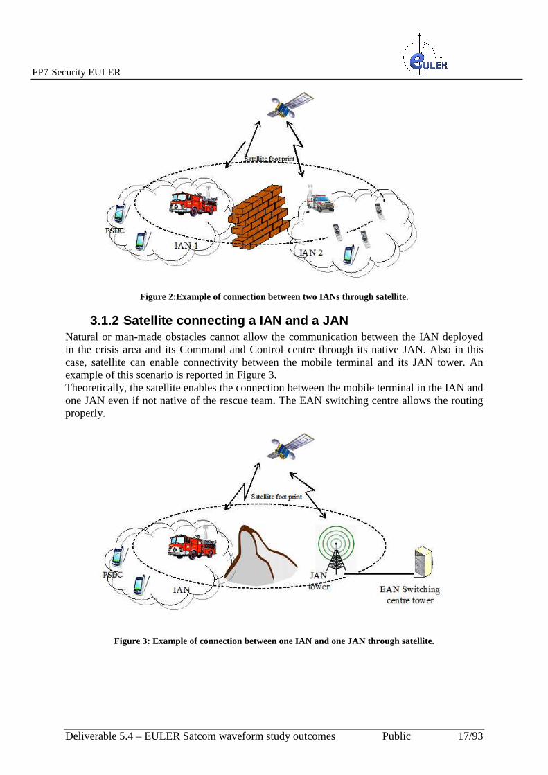
Figure 2:Example of connection between two IANs through satellite.
3.1.2 Satellite connecting a IAN and a JAN Natural or man-made obstacles cannot allow the communication between the IAN deployed in the crisis area and its Command and Control centre through its native JAN. Also in this case, satellite can enable connectivity between the mobile terminal and its JAN tower. An example of this scenario is reported in Figure 3. Theoretically, the satellite enables the connection between the mobile terminal in the IAN and one JAN even if not native of the rescue team. The EAN switching centre allows the routing properly.
Figure 3: Example of connection between one IAN and one JAN through satellite.

FP7-Security EULER
Deliverable 5.4 – EULER Satcom waveform study outcomes Public 18/93
3.2 Satellite constraints Due to its nature, satellite network has advantages and disadvantages when traffic is transmitted on it. The high distance from the land provides a wide covered area but as also produces two main (possibly disadvantageous) effects:
- low power at the destination receiver - large delays between transmitter and receiver.
The first problem has the effect to require a more sensitive receiver. In detail, a new design for link budget should be performed in order to manage the received power when it is too low. The second problem has two effects:
- the necessity to manage the higher delay in communication protocol; for example WiMAX protocols are not able to manage delays on the order of few hundreds of ms between uplink and downlink subframe.
- the necessity to manage differential delays among users in the wide footprint of the satellite.
Figure 4 shows the last described case. The reported general scheme of a connection among users provided of mobile terminals to an earth station through satellite highlights the different delay experienced by mobile terminal in position A, position B and position C.
Figure 4: General scheme for a mobile terminal connected to the earth station through the satellite.
3.3 Supported services For any public safety agency, the ability to keep communications running in the face of emergencies or natural disasters is a critical aspect. Brigades operating on the field must have constant access to voice and data, even when local network services are down. By providing

FP7-Security EULER
Deliverable 5.4 – EULER Satcom waveform study outcomes Public 19/93
emergency communications services during emergency situations like these, satellite technology helps save lives. In order to fulfil this mission and insure public safety in any situation, EULER SATCOM has to expand emergency communications network. It needed a comprehensive and reliable backup and emergency communications system to ensure critical communications always stay online and to enable coordination with other agencies (national and international) ensuring interoperability. In addition, it needed a solution with the capability to tie radio bridges together and seamlessly provide mixed backhaul when terrestrial lines were down, without compromising their ability to deliver full network interoperability. In many recent disaster like Hurricane Katrina, Abruzzo and China earthquake terrestrial networks were broken so satellite was the only possible solution to provide communication. Nevertheless with the current satellite networks, many of the solutions are too costly, or just didn’t work properly, and none of them supported all needed requirements. So the intent in Euler project is to design and implement an innovative satellite solution, enabling it to successfully fulfil its mission of protecting the public. The two main users communities of the Emergency Response Service are the national civil protections and the humanitarian aid.
Among them the services target the following users :
• Decision makers require overall assessment of crises such as information on location, area and population affected by disasters. This information needs to be synthetic and is more effective when provided in a graphical form. For receiving this information, decision makers increasingly rely on internet tools.
• Implementing partners are for example UN agencies or the NGO community; they plan and deliver aid. Implementers at headquarters increasingly rely on specialized Web sites for disaster alerts. NGOs increasingly provide custom-made maps to their field officials.
• Field officials and experts need and regularly use geographic information. This is because NGOs need to know precisely the location of crisis/disasters, the affected people, the transport network and interruptions to it. Traditional paper maps remain the most common source of geographic information for field officials although maps start to be disseminated to in-field operatives also through the Internet.
Starting from user requirements aforementioned an upgraded communications solution should support its full range of requirements, including support for converged VoIP (Voice over IP), RoIP (Radio over IP), video, data and radio backhaul. The system needed to be mobile, independent of terrestrial networks, provide interoperability between state agencies as well as access to the PSTN to integrate efforts with FEMA or other federal agencies. Leveraging lessons learned from past experiences, including hurricanes Katrina in 2005, ideal network would utilize broadband satellite connectivity as its core network. During Katrina, critical voice and data communications were offline. Wireline circuits were damaged, and wireless and cellular technologies were knocked out since they are dependent on terrestrial communications. Land Mobile Radio (LMR) systems experienced blackouts since they are also dependant on the local land-based infrastructure. Unlike these traditional connectivity solutions, satellite networks completely bypass the local terrestrial infrastructure and provide a completely independent, wireless last-mile solution that provides ultra-reliable services.

FP7-Security EULER
Deliverable 5.4 – EULER Satcom waveform study outcomes Public 20/93
A set of services that should be supported by EULER SATCOM are listed below:
- Voice o Selective/individual call o Group call o Emergency call
- Video o Video call o broadcast/multicast Video
- Traffic data o sensor data (temperature, humidity, CO, CO2, …) o location update/reporting o instant messaging o e-mails o images (high, low resolution) o map (GIS, …) o health parameters o other data traffic
- Management/control data o control data (routing update, call signalling)
FP7-Security EULER
Deliverable 5.4 – EULER Satcom waveform study outcomes Public 21/93
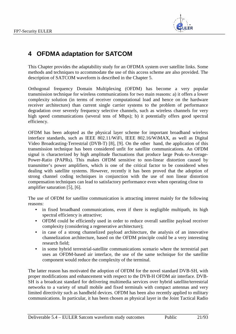
4 OFDMA adaptation for SATCOM This Chapter provides the adaptability study for an OFDMA system over satellite links. Some methods and techniques to accommodate the use of this access scheme are also provided. The description of SATCOM waveform is described in the Chapter 5. Orthogonal frequency Domain Multiplexing (OFDM) has become a very popular transmission technique for wireless communications for two main reasons: a) it offers a lower complexity solution (in terms of receiver computational load and hence on the hardware receiver architecture) than current single carrier systems to the problem of performance degradation over severely frequency selective channels, such as wireless channels for very high speed communications (several tens of Mbps); b) it potentially offers good spectral efficiency. OFDM has been adopted as the physical layer scheme for important broadband wireless interface standards, such as IEEE 802.11/WiFi, IEEE 802.16/WiMAX, as well as Digital Video Broadcasting-Terrestrial (DVB-T) [8], [9]. On the other hand, the application of this transmission technique has been considered unfit for satellite communications. An OFDM signal is characterized by high amplitude fluctuations that produce large Peak-to-Average-Power-Ratio (PAPRs). This makes OFDM sensitive to non-linear distortion caused by transmitter’s power amplifiers, which is one of the critical factor to be considered when dealing with satellite systems. However, recently it has been proved that the adoption of strong channel coding techniques in conjunction with the use of non linear distortion compensation techniques can lead to satisfactory performance even when operating close to amplifier saturation [5], [6]. The use of OFDM for satellite communication is attracting interest mainly for the following reasons:
• in fixed broadband communications, even if there is negligible multipath, its high spectral efficiency is attractive;
• OFDM could be efficiently used in order to reduce overall satellite payload receiver complexity (considering a regenerative architecture);
• in case of a strong channelized payload architecture, the analysis of an innovative channelization architecture, based on the OFDM principle could be a very interesting research field;
• in some hybrid terrestrial-satellite communications scenario where the terrestrial part uses an OFDM-based air interface, the use of the same technique for the satellite component would reduce the complexity of the terminal.
The latter reason has motivated the adoption of OFDM for the novel standard DVB-SH, with proper modifications and enhancement with respect to the DVB-H OFDM air interface. DVB-SH is a broadcast standard for delivering multimedia services over hybrid satellite/terrestrial networks to a variety of small mobile and fixed terminals with compact antennas and very limited directivity such as handheld devices. OFDM has been also recently applied to military communications. In particular, it has been chosen as physical layer in the Joint Tactical Radio

FP7-Security EULER
Deliverable 5.4 – EULER Satcom waveform study outcomes Public 22/93
System (JTRS) Wide-Band Networking Waveform (WNW) to support network centric operations [7]. OFDM modulation has recently been explored in JTEO’s research efforts for identifying the optimal air-interface for MILSATCOM networks through Wideband Global SATCOM (WGS) systems. In all these applications, one critical issue that remains is the high PAPR and hence, low power efficiency. PAPR reductions techniques have been extensively studied and can be applied to satellite communications. However, one breakthrough in the utilization of OFDM in satellite communications is represented by the novel concept of Constant Envelope OFDM (CE-OFDM) [13]. CE-OFDM transforms the OFDM signal, by way of phase modulation, to a signal designed for efficient power amplification in order to reduce large Peak-to-Average-Power-Ratio. OFDM and OFDMA based communication between user terminals and a terrestrial base station have been described in IEEE 802.16e/D7: Air Interface for fixed and Mobile Broadband Wireless Access Systems and IEEE Std 802.16 -2004: Air Interface for Fixed Broadband Wireless Access Systems. The methods contained in these standards include protocols applicable to terrestrial systems for allocating OFDM and OFDMA resources to user terminals and base stations for uplink and downlink communications, methods for synchronizing uplink and downlink frames at the user terminal and base stations so that they do not overlap in time (applicable to Time Division Duplexing (TDD) and Half Frequency Division Duplexing (HFDD) modes), and methods for synchronizing all sets of tones comprising an OFDMA channel arriving from different user terminals at a base station. In a TDD system, communicating terminals use a common channel, but transmit and receive at different times. HFDD is similar to TDD, in that terminals transmit and receive at different times. However, in HFDD, a terminal uses different frequencies for transmitting and receiving. As terrestrial network have different characteristics with respect to satellite one, the use of OFDMA for SATCOM requires some adaptations. In this section, some methods for controlling orthogonal frequencies division multiple access (OFDMA) communications over satellite links are provided. The described methods include estimating differential delay in a satellite spotbeam between a mean propagation delay in the spotbeam and a propagation delay between a user terminal in the spotbeam and a satellite, estimating an overlap between an OFDMA uplink frame and OFDMA downlink frame as a result of differential delay, and providing a guard band in the OFDMA uplink frame and/or the OFDMA downlink frame to reduce an overlap between remaining portions of OFDMA uplink frame and the OFDMA downlink frame other than the guard band. In particular, the proposed methods for estimating the differential delay include defining a ranging window that has a duration of at least a duration of an OFDMA uplink frame plus twice a maximum expected differential delay for OFDMA uplink frames, and receiving a ranging codeword within the ranging window. The ranging codeword can include a plurality of ranging symbols and/or may be spread over a plurality of OFDMA subchannels.

FP7-Security EULER
Deliverable 5.4 – EULER Satcom waveform study outcomes Public 23/93
The methods can further include transmitting a ranging response in response to the ranging codeword , the ranging response designates a timing delay for use in synchronizing uplink transmissions. The ranging response can designate guardband(s) to be used on uplink and/or OFDMA downlink frames and/or designates at least one subregion of an OFDMA uplink frame and/or an OFDMA downlink frame as unused.
4.1 Technical analysis of OFDMA adaptation to SATCOM The reference model for the analysis of the adaptation of OFDMA for satellite links is shown Figure 5. It includes a satellite with transparent transponder, a user terminal configured to communicate with the satellite via a satellite frequency over one of the satellite links, and a scheduler. The scheduler is configured to perform the following operations:
• estimate a differential delay in a satellite spotbeam between a mean propagation delay in the spotbeam and a propagation delay between the user terminal in the spotbeam and the satellite,
• estimate an overlap between an OFDMA uplink frame and an OFDMA downlink frame as a result of the differential delay for different user terminal,
• provide a guard band in the OFDMA uplink frame and/or the OFDMA downlink frame to reduce an overlap at the user terminal between the remaining portions of the OFDMA uplink frame and the OFDMA downlink frame other than the guard band.
The user terminal have to be configured to communicate with a satellite by using OFDMA communications and to receive a designation of a guardband to be used over an OFDMA uplink frame transmitted by the terminal to the satellite, and the terminal is configured not to transmit OFDMA signals during the uplink guardband so to reduce an overlap between the OFDMA uplink frame and a OFDMA downlink frame. As well known, in the OFDM/OFDMA standards IEEE P802.16e and IEEE 802.16-2004, only terrestrial systems and methods are considered. Accordingly, the standards may not be adequately address systems including satellite communications elements which experience effects, such as noise, delay, attenuation, etc., that can be different from those experienced by terrestrial systems. In an OFDMA system, the available bandwidth is divided into orthogonal tones or carrier frequencies. Each user is allocated a set of orthogonal tones for use in communicating with a base station. In a satellite-based system using OFDMA, the allocated set of tones may be relatively small, due to power and/or bandwidth constraints. In a terrestrial OFDMA system, resources allocation typically consists of subchannels (or sets) of 4 tones. Frame synchronization in time division duplexing (TDD) mode can be accomplished easily in a terrestrial system, since the propagation delays are relatively very small and the differential delays can be considered negligible. Thus, the synchronization of the uplink sets of tones can be achieved through a small window of adjustment since the differential delays are small. Synchronization can be aided by the use of ranging codes that are sent downlink to the user terminal. Responses to the ranging code permit the base station to determine the distance of the user terminal, and thus the delay associated with the user terminal, from the base station. The relatively large available bandwidth in a terrestrial communication system allows the ranging code to be accommodated within a short period of

FP7-Security EULER
Deliverable 5.4 – EULER Satcom waveform study outcomes Public 24/93
time. In contrast the relatively restricted power and bandwidth on satellite channels and increased propagation and differential delays can make it desirable to change the resource allocation systems and methods, and/or synchronization and ranging methods. Terrestrial reuse of satellite frequencies, as authorized by the Federal Communications Commission’s Ancillary Terrestrial component (ATC) Order, FCC 03-15, allows the same user terminal to communicate with terrestrial base stations and with satellites and associated earth stations. The FCC Order stipulates transparency and “safe-harbour” clauses so that dual mode satellite and terrestrial user terminals can operate over hybrid satellite ATC-networks. To develop efficient dual-mode user devices, the satellite mode protocol should be adapted from and be closely related to the terrestrial mode protocol. Satellite channels impose power and bandwidth constraints, and generally have increased propagation delay between user terminals and earth stations and increased differential delays between the earth station and any two user terminals when compared to terrestrial channels. A wireless communication protocol for satellite channels that have to be adapted from a terrestrial protocol has to account for these constraints and/or delays. For an OFDMA based protocol, the use of such techniques can change the power, bandwidth and/or delay of an uplink signal, which can impact aspects of the protocol such as resource allocation, synchronization of uplink and sets of OFDMA tones and/or allocation of uplink resources as small as a single subcarrier. This Chapter describes methods and techniques for allocating OFDMA resources to user terminals and earth stations in the form of tones carrying user data and tones carrying pilot information for control purposes, in a manner conducive to the power and bandwidth characteristics of satellite channels and the comparatively slow variation of satellite channel. These characteristics may allow the allocation of a small number of tones for communication to and from one user terminal. Moreover, the nature of the channel variation can allow allocation of a large number of symbols (e.g. 8) for each pilot symbol in each allocation. This is because the pilot symbols are primarily used for channel quality measurements. Since the satellite channel is slow-varying relative to a terrestrial channel, the pilots can be needed less frequently to monitor the changing quality of the channel. The scheduler of the uplink resources in a Half Frequency Division Duplexing (HFDD) mode system residing at the satellite and/or earth station synchronizes the downlink and uplink frames according to a timing reference at the satellite /earth station so that the uplink and the downlink frames cannot overlap at the user terminal and/or the earth station. That is, the downlink and the uplink frames can be synchronized so that, for example, a user terminal is not required to simultaneously transmit an uplink frame and receive a downlink frame or any portion thereof. This implies that the uplink scheduler has to determine the portions of the uplink frame that do not overlap with the downlink frame and populate these portions with the uplink data. The overlapped portions of the uplink frame may not be used for data transmission. According to the proposed system, the uplink scheduler determines an amount of advance or retardation of the transmission epoch of the uplink frame as a function of the terminal’s differential delay offset from a mean propagation delay. The amount of advance or retardation is communicated to the user terminal, which can appropriately advance or delay its transmitted uplink signal to cause the uplink signal to arrive at the satellite/earth station at the appropriate epoch.

FP7-Security EULER
Deliverable 5.4 – EULER Satcom waveform study outcomes Public 25/93
The terminal uses a small portion of the uplink bandwidth over a time of period comprising a number of symbol periods to transmit a ranging code to the satellite/earth station identifying its position in terms of its differential delay relative to the mean propagation delay. The satellite/earth station in turn uses a ranging window sized to accommodate a maximum expected differential advance/delay of user terminals, starting a known epoch in the uplink frame. The ranging window is used to capture the ranging code. In response to determining the range of the user terminal, the satellite/earth station requests the user terminal to advance or retard its uplink transmission accordingly. Some methods for allocating resources in bandwidth and time for OFDMA communication between a user terminal and an earth station via a satellite are described below. In particular one or more orthogonal tones can be allocated over many symbol periods. The symbol periods can be used or not used by the user terminal and/or earth station depending on whether or not the symbol periods overlap other symbol periods. A system according to the described approach is illustrated in Figure 5. As shown therein, a first user terminal A has geographic coordinates (xa,ya). The user terminal A is located within a cell within a geographic footprint of a satellite, which may be a low-earth orbiting satellite (LEO) a medium –earth orbiting satellite (MEO), and/or geostationary satellite. The satellite, which includes an antenna and an electronic system, communicates with at least one earth station, which includes an antenna and electronic system via feeder link. The electronic system of the earth station can include a resources scheduler that is configured to provide synchronization and/or ranging functions as described in more details below. The satellite antenna can include an array of antenna feed elements, which generate signals covering respective overlapping in the geographic areas in the geographic footprint of the satellite. The first user terminal A communicates with the satellite communication link L1. A second user terminal B is located within the cell at geographic coordinates (xb,yb), and communicates with the satellite via a second satellite communications link L2. Because the cell can be relatively large compared to cells of terrestrial (land-based) communication systems, the path length of the communication link L1 between the first user terminal A and the satellite can be significantly different from the path communication link L2 between the second user terminal and the satellite. As a consequence, a satellite transmission different delay associated with the first use terminal may be significantly different from the transmission delay associated with the second user terminal.

FP7-Security EULER
Deliverable 5.4 – EULER Satcom waveform study outcomes Public 26/93
Figure 5: Reference model for a Satellite System.
Figure 5 shows also a block diagram of a satellite. The satellite includes an antenna and an electronic system. The electronics system of satellite include a resource scheduler that is configured to perform synchronization and/or ranging functions as described in more detail below in addition to or instead of a resource scheduler in the earth station, Accordingly, synchronization and/or ranging techniques for satellite communication can be provided by functionality in a satellite and/or in an earth station. Figure 6 and Figure 7 show a possible scheme of symbol structures for resources allocation where each subchannel includes a single tone or (subcarrier). Each user terminal to satellite/earth station communication link in either direction (uplink and downlink) can be allocated a slot including one or more subchannels according to the bandwidth required, and each slot can span a number of symbols. For example, as illustrated in Figure 6, a slot can include symbols, one of which is reserved for pilot signals (“P”). The remaining eight symbols may be used for data (“D”). As illustrated in Figure 7, slots can be assigned with more granularity. For example, a slot can include three symbols, with one symbol used for pilot signals (“P”) and two symbols used for data (“D”). This granularity in assigning of satellite resources allows an use opportunistic of the band of the transponder, optimizing the spectral efficiency. The following sections of this Chapter describe more in details the synchronization and ranging procedure needed to use OFDMA system over satellite.

FP7-Security EULER
Deliverable 5.4 – EULER Satcom waveform study outcomes Public 27/93
Figure 6: Example of symbol structure for resource allocation.
Figure 7: Example of symbol structure for resource allocation with high granularity for resources
allocation.
4.1.1 Synchronization procedure The synchronization is performed to identify and permit a user terminal to use periods of time or uplink data that do not overlap with downlink frames so that a user terminal may not be required to both transmit an uplink signal and receive a downlink signal at the same time. Figure 8, 9 and 10 show some potential effects of large differential delays in satellite channels on frame synchronization at the user terminal. Frames are synchronized for a mean propagation delay, but can be retarded to account for lower delays and/or advanced to account for larger delays due to the varying differential delays of user terminals in a satellite frequency band (spot beam).

FP7-Security EULER
Deliverable 5.4 – EULER Satcom waveform study outcomes Public 28/93
In particular, Figure 8,9,10 shows the impact of large differential delays around the mean propagation on the uplink and downlink frame synchronization in a Half Frequency Division Duplexing mode. In Figure 8,9,10, downlink subframes DL1, DL2, etc., are sent by a satellite/earth station (SAT) to a user terminal (UT). Uplink subframes, including uplink subframe UL1, are sent by the user terminal to the satellite /earth station. If all the user terminals experienced relatively the same propagation delay as occur in conventional terrestrial networks, then the uplink and downlink frames would be synchronized . i.e., there would be no overlap between the uplink and the downlink subframes at the user terminal as depicted by the mean propagation delay timeline in Figure 8. In Figure 8, the downlink subframe DL1 is received by the user terminal after a transmission delay of Dmean. After receiving the downlink subframe DL1, the user terminal UT sends the uplink subframe UL1 which arrives at the satellite/earth station at the appropriate epoch following the transmission delay Dmean. In satellite networks, due to the large geographical area covered by a spot beam, user terminals in the spot beam can experience significant differential delays around this mean delay. That is, signals from some user terminals may have transmission delays that are measurably longer than the mean propagation delay, while signals from other user terminals can have transmission delays that are measurably shorter than the mean transmission delay. As a result, the uplink and the downlink subframes may overlap each other at the user terminal as shown in Figure 9 and Figure 10. For example, referring to Figure 9, the downlink subframes DL1 and DL2 are received by the user terminal after a transmission delay D1, which is shorter than the mean transmission delay Dmean. After receiving the downlink subframe DL1, the user terminal UT sends the uplink subframe UL1. However due to the differential transmission delay, in order to send the uplink subframe UL1 far enough in advance to ensure that it arrives at the satellite /earth station at the appropriate epoch, the uplink subframe UL1 would overlap the next incoming downlink subframe DL2 at the user terminal. In the example illustrated in Figure 10 instead, the downlink subframes DL1 and DL2 are received by the user terminal after a transmission delay D2, which is longer than the mean transmission delay Dmean. In this case, in order to send the uplink subframe UL1 far enough in advance to ensure that it arrives at the satellite/earth station at the appropriate epoch, the uplink subframe UL1 would overlap the incoming downlink subframe DL1 at the user terminal.
Figure 8: Potential effects of different differential delays in satellite channels on the frame synchronization
at the user terminal.

FP7-Security EULER
Deliverable 5.4 – EULER Satcom waveform study outcomes Public 29/93
Figure 9: Potential effects of different differential delays in satellite channels on the frame synchronization at the user terminal (D1<Dmean).
Figure 10: Potential effects of different differential delays in satellite channels on the frame
synchronization at the user terminal (D2> Dmean).
Figure 11-13 illustrate some mechanisms to uplink allocations in differential delay situations such which are able to avoid potential overlapping described above. In particular, Figure 11-13 depict how the proposed method to use differential delay to handle different propagation delay can address overlapping uplink and downlink subframes. The uplink subframe is divided into regions. The resource scheduler in the satellite/earth station, which has knowledge of the positions of the all the user terminals, and their associated propagation delays, allocates uplink resources on a subregion by subregion basis, so that the user terminal does not transmit while receiving on the downlink. For example, in the cases illustrated in Figure 11-13, each uplink subframe is divided into a plurality of subregions. Each subregion can include at least one slot including at least one pilot symbol, as illustrated in Figure 6 and Figure 7. Some of the subregions can be unused, so that data can be contained in less than all of the subregions of an uplink subframe to avoid having overlapping uplink and downlink subframes at the user terminal. More in details, for user terminals having the propagation delay equal to mean propagation delay, data can be carried in any of the subregions, as shown in Figure 11. Referring to Figure 12, for low differential delays (e.g. propagation delays less than the mean propagation delay), the subregions carrying data are in the initial part of the subframe, while the subregions that would otherwise overlap a downlink subframe DL2 are not used.

FP7-Security EULER
Deliverable 5.4 – EULER Satcom waveform study outcomes Public 30/93
Figure 11: Illustration of an uplink allocation for UT having propagation delay equal to the mean
propagation delay.
Figure 12: Illustration of an uplink allocation for UT having propagation delay less than the mean
propagation delay.
Figure 13: Illustration of an uplink allocation for UT having propagation delay greater than the mean
propagation delay.
As shown in Figure 13, for longer differential delays (e.g., propagation delays greater than the mean propagation delay), data can be carried in subregions in the latter part of the subframe, while the other subregions are not used The methods described above in connection with Figure 14-18 allow to achieve synchronization of the uplink frames without the need for intelligence overhead. However, resources may be wasted since synchronization is achieved through repetition and/or nonuse of some portions of an uplink subframe. Some techniques can reduce wastage of resources, but can require the addition of intelligence/processing complexity that may affect the delay
FP7-Security EULER
Deliverable 5.4 – EULER Satcom waveform study outcomes Public 31/93
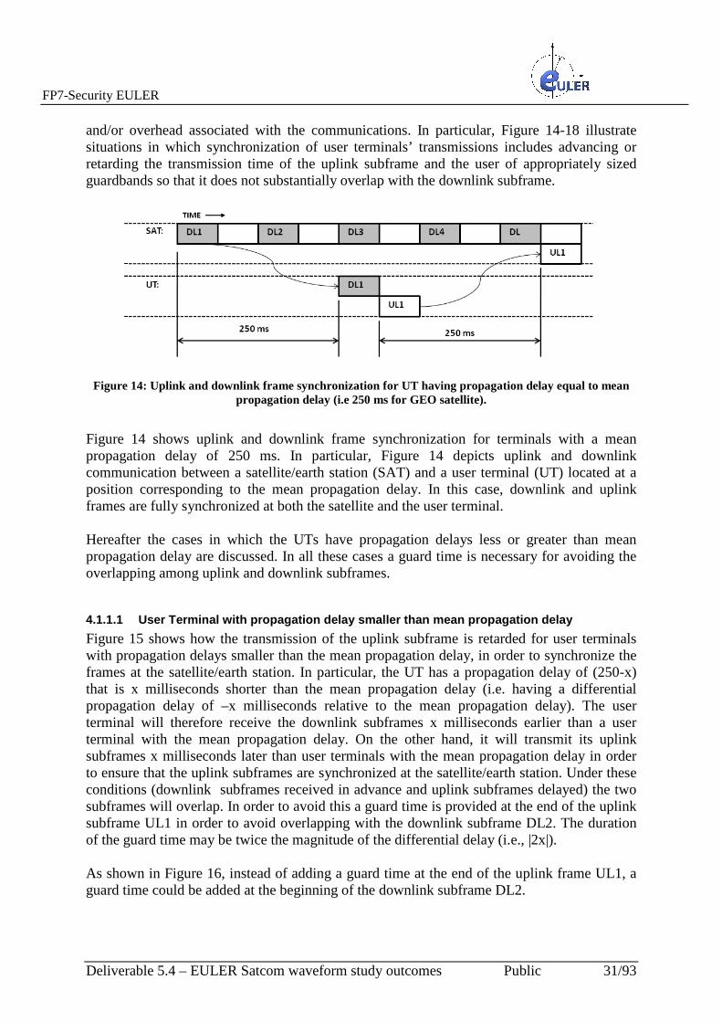
and/or overhead associated with the communications. In particular, Figure 14-18 illustrate situations in which synchronization of user terminals’ transmissions includes advancing or retarding the transmission time of the uplink subframe and the user of appropriately sized guardbands so that it does not substantially overlap with the downlink subframe.
Figure 14: Uplink and downlink frame synchronization for UT having propagation delay equal to mean
propagation delay (i.e 250 ms for GEO satellite).
Figure 14 shows uplink and downlink frame synchronization for terminals with a mean propagation delay of 250 ms. In particular, Figure 14 depicts uplink and downlink communication between a satellite/earth station (SAT) and a user terminal (UT) located at a position corresponding to the mean propagation delay. In this case, downlink and uplink frames are fully synchronized at both the satellite and the user terminal. Hereafter the cases in which the UTs have propagation delays less or greater than mean propagation delay are discussed. In all these cases a guard time is necessary for avoiding the overlapping among uplink and downlink subframes.
4.1.1.1 User Terminal with propagation delay smaller than mean propagation delay
Figure 15 shows how the transmission of the uplink subframe is retarded for user terminals with propagation delays smaller than the mean propagation delay, in order to synchronize the frames at the satellite/earth station. In particular, the UT has a propagation delay of (250-x) that is x milliseconds shorter than the mean propagation delay (i.e. having a differential propagation delay of –x milliseconds relative to the mean propagation delay). The user terminal will therefore receive the downlink subframes x milliseconds earlier than a user terminal with the mean propagation delay. On the other hand, it will transmit its uplink subframes x milliseconds later than user terminals with the mean propagation delay in order to ensure that the uplink subframes are synchronized at the satellite/earth station. Under these conditions (downlink subframes received in advance and uplink subframes delayed) the two subframes will overlap. In order to avoid this a guard time is provided at the end of the uplink subframe UL1 in order to avoid overlapping with the downlink subframe DL2. The duration of the guard time may be twice the magnitude of the differential delay (i.e., |2x|). As shown in Figure 16, instead of adding a guard time at the end of the uplink frame UL1, a guard time could be added at the beginning of the downlink subframe DL2.

FP7-Security EULER
Deliverable 5.4 – EULER Satcom waveform study outcomes Public 32/93
Figure 15: Uplink and downlink frame synchronization for UT with differential propagation delay of –x
milliseconds relative to the mean propagation delay. A guard time of |2x| is provided at the end of the uplink subframe UL1 to avoid overlapping.
Figure 16: Uplink and downlink frame synchronization for UT with differential propagation delay of –x milliseconds relative to the mean propagation delay. A guard time of 2|x| ms is added at the beginning of
the downlink subframe DL2 to avoid overlapping.
FP7-Security EULER
Deliverable 5.4 – EULER Satcom waveform study outcomes Public 33/93
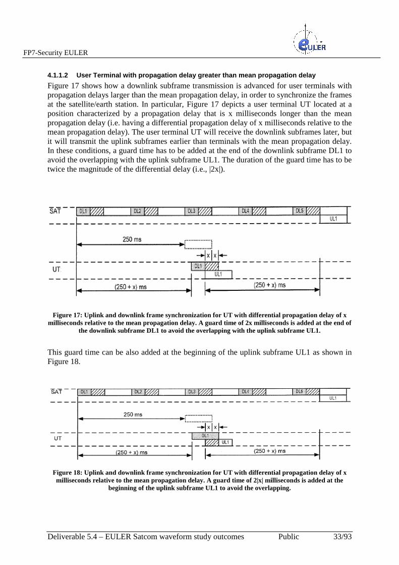
4.1.1.2 User Terminal with propagation delay greater than mean propagation delay
Figure 17 shows how a downlink subframe transmission is advanced for user terminals with propagation delays larger than the mean propagation delay, in order to synchronize the frames at the satellite/earth station. In particular, Figure 17 depicts a user terminal UT located at a position characterized by a propagation delay that is x milliseconds longer than the mean propagation delay (i.e. having a differential propagation delay of x milliseconds relative to the mean propagation delay). The user terminal UT will receive the downlink subframes later, but it will transmit the uplink subframes earlier than terminals with the mean propagation delay. In these conditions, a guard time has to be added at the end of the downlink subframe DL1 to avoid the overlapping with the uplink subframe UL1. The duration of the guard time has to be twice the magnitude of the differential delay (i.e., |2x|).
Figure 17: Uplink and downlink frame synchronization for UT with differential propagation delay of x
milliseconds relative to the mean propagation delay. A guard time of 2x milliseconds is added at the end of the downlink subframe DL1 to avoid the overlapping with the uplink subframe UL1.
This guard time can be also added at the beginning of the uplink subframe UL1 as shown in Figure 18.
Figure 18: Uplink and downlink frame synchronization for UT with differential propagation delay of x milliseconds relative to the mean propagation delay. A guard time of 2|x| milliseconds is added at the
beginning of the uplink subframe UL1 to avoid the overlapping.

FP7-Security EULER
Deliverable 5.4 – EULER Satcom waveform study outcomes Public 34/93
As described above, guard times can be added the beginning and/or end of the downlink and/or uplink subframes, and/or allocated between the downlink and uplink subframes, depending on the relative amount of bandwidth required for uplink versus downlink transmissions. For example, some applications, such as voice telephony, require relatively symmetric data rates between uplink and downlink transmission. In such cases, it may be desirable to allocate guard times to both the uplink and downlink subframes. However other application such as internet browsing and content distribution (e.g. broadcast or multicast distribution) could require larger data rates for downlink communication than for uplink communication. In such cases it may be desirable to add guard times to the uplink subframes only, to avoid reducing the available downlink bandwidth. The appropriate guard times, can be determined by the resource scheduler in the satellite/earth station in response to determining the propagation delay for a terminal, and have to be transmitted to the terminal by the satellite/earth station.
4.1.2 Ranging procedure The ranging procedure regards the methods and the techniques for synchronizing the arrival epoch of all sets of tones of an OFDMA system arriving from disparate user terminals at an earth station via a satellite. Many techniques can be used and adapted to satellite environments. Some of these techniques, which employ ranging operation, are illustrated in the following figures. More in details, Figure 19 shows a ranging channel structure for satellite applications and Figure 20 illustrates a ranging channel window which is larger than the frame size to accommodate large differential delays common in satellite channels. In particular, referring to Figure 19, a ranging codeword R could be embedded as a part of an uplink data frame, and could occupy a number of tones/subchannels across a number of symbols to account for bandwidth constraints in satellite communications systems.
Figure 19: Example of allocation of subchannels /symbols to a ranging codeword.

FP7-Security EULER
Deliverable 5.4 – EULER Satcom waveform study outcomes Public 35/93
Figure 20: Ranging window used at a satellite /earth station.
Referring to Figure 20, a relatively large ranging window can be used at the satellite/earth station due to the high differential delays. In particular, a ranging window can be used to allow the ranging channel codeword to be received by the satellite/earth station during a sufficiently large time window. For example, the ranging window may have a duration Trw given as:
Trw=Tsubframe +2|Tmaxdd| where Tsubframe is the duration of an uplink subframe and Tmaxdd is the maximum expected differential delay, so that the ranging window is sized to tolerate ranging codewords that are advanced or retarded by up to a maximum differential delay Tmaxdd. In a real implementation, a ranging window of at least about 40 ms can be adopted, as depicted in Figure 20. Figure 21 shows ranging operations in a satellite channel. As shown therein, the satellite/earth station transmits a downlink subframe DL1. In response, the user terminal transmits a ranging subframe, which is received by the satellite/earth station after a propagation delay D1 associated with the user terminal. Without ranging, an uplink frame would arrive at a random or unknown epoch. However, the arrival time of the ranging uplink frame is within the ranging window, which is sized to extend longer than a subframe by at least maximum advance time on one end and a maximum delay time on the other. In the example illustrated in Figure 21, the propagation delay D1 associated with the user terminal is less than the average delay, so that the ranging subframe is received slightly ahead of time, but still within the ranging window. Thus, the satellite/earth station is able to respond to the ranging request with a ranging response. The ranging response can designate a timing delay x for use by the user terminal in synchronizing uplink transmissions. The user terminal receives the ranging response and uses timing information contained therein to advance or delay its transmission time. The next uplink subframe UL1 is thereby synchronized at the satellite/earth station. The ranging response can also designate guardband(s) to be used on the uplink and/or downlink subframes and/or may designate one or more subregions as unused to avoid overlaps between uplink and downlink frames at the user terminal.
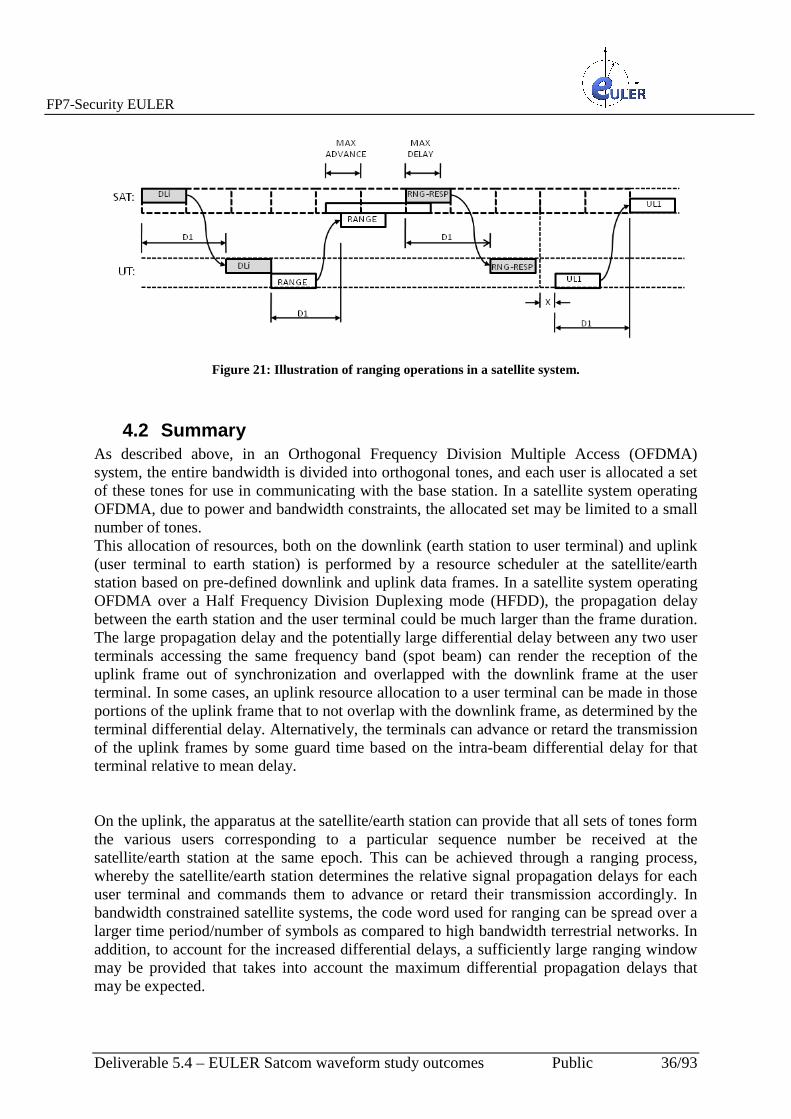
FP7-Security EULER
Deliverable 5.4 – EULER Satcom waveform study outcomes Public 36/93
Figure 21: Illustration of ranging operations in a satellite system.
4.2 Summary As described above, in an Orthogonal Frequency Division Multiple Access (OFDMA) system, the entire bandwidth is divided into orthogonal tones, and each user is allocated a set of these tones for use in communicating with the base station. In a satellite system operating OFDMA, due to power and bandwidth constraints, the allocated set may be limited to a small number of tones. This allocation of resources, both on the downlink (earth station to user terminal) and uplink (user terminal to earth station) is performed by a resource scheduler at the satellite/earth station based on pre-defined downlink and uplink data frames. In a satellite system operating OFDMA over a Half Frequency Division Duplexing mode (HFDD), the propagation delay between the earth station and the user terminal could be much larger than the frame duration. The large propagation delay and the potentially large differential delay between any two user terminals accessing the same frequency band (spot beam) can render the reception of the uplink frame out of synchronization and overlapped with the downlink frame at the user terminal. In some cases, an uplink resource allocation to a user terminal can be made in those portions of the uplink frame that to not overlap with the downlink frame, as determined by the terminal differential delay. Alternatively, the terminals can advance or retard the transmission of the uplink frames by some guard time based on the intra-beam differential delay for that terminal relative to mean delay. On the uplink, the apparatus at the satellite/earth station can provide that all sets of tones form the various users corresponding to a particular sequence number be received at the satellite/earth station at the same epoch. This can be achieved through a ranging process, whereby the satellite/earth station determines the relative signal propagation delays for each user terminal and commands them to advance or retard their transmission accordingly. In bandwidth constrained satellite systems, the code word used for ranging can be spread over a larger time period/number of symbols as compared to high bandwidth terrestrial networks. In addition, to account for the increased differential delays, a sufficiently large ranging window may be provided that takes into account the maximum differential propagation delays that may be expected.

FP7-Security EULER
Deliverable 5.4 – EULER Satcom waveform study outcomes Public 37/93
5 EWF adaptation to Satellite environments In this chapter we try to identify limitations of the EWF (subset of the IEEE 802.16e) when used in a satellite link. We will suggest modifications of EWF in order to have compatibility with the satellite channel. The derived waveform is the ESWF. The analysis will be focused on three in mains aspects:
• Physical Layer • Medium access control layer, MAC • Security sub-layer
5.1 EWF Impact analysis for Satellite channels
5.1.1 Impact on the physical layer
5.1.1.1 Channels to be considered: Geostationary channels Considering a geostationary satellite, GS, the configuration of the deployed ESWF is represented in Figure 22. All the satellite terminal, ST, which are in the area covered by the spot beam of the satellite, can be connected to the HUB.
ST
Satellite
HUB
Spot beam
STST
ST
Figure 22: ESWF deployed over a geosynchronous satellite and only a spot beam. A deployed system can
include more spot beams.
The coverage of the satellite consists of a number of spot beams (similar to cells in the terrestrial context). Usually every spot have a mean delay with relative small differences between every two users in the same spot beam. All the spots beams can be characterized by a mean delay with delay differences between all the users. The differential delay is the maximum difference of delay between all users. The physical level should be adapted in order to accommodate the mean delay of the communication between the HUB and the ST and the maximum differential delay considering all active spots beams and ST. A simplified model of the geostationary satellite channel must include the following aspects:
• Delay: much more delay (around 260 ms HUB-satellite-ST) than the terrestrial channels and longer differential delays between each two ST and the HUB.
• Power constrained in the satellite (we will not consider in this memorandum link budget aspects neither other transmission impairments).
• Linear filtering on board (the input and output multiplexers). This linear filtering contributes to the intersymbol interference, ISI.
• Non linear effects due to the high power amplifier, HPA. In the conventional frequency translation transponder the uplink signal is translated to an intermediate

FP7-Security EULER
Deliverable 5.4 – EULER Satcom waveform study outcomes Public 38/93
frequency, amplified, up converted, amplified and transmitted again to the earth. The direct transponder the uplink frequency is converted directly to the down link frequency and after one or more stages of amplification, re-transmitted to the ground.
• The channel is slow time variant compared with the terrestrial channel.
• Multipath effects: generally is assumed that the direct component is relatively strong compared with others paths that can be neglected. This is the single path approach. However a multipath propagation similar to that experienced in the terrestrial cellular network may occur.
5.1.1.2 Channels to be considered: Low/Medium earth satellite channels Non-geostationary systems have smaller propagation delays and propagation loss which yields smaller handsets compared with geostationary satellites. Therefore LEO/MEO satellites are the most appropriate systems to offer personal communication due to their closer proximity to the earth. However their low altitude and high flyby speed which combine to produce a highly variable ground-space communication channel. On board processing enables to use spot beam antennas to increase signal power and directivity. This feature means that the SS size can be decreased. Up link and down link are decoupled, which allows to be optimized separately. Different alternative should be considered for selecting the proper channel model. The fast changing channel properties manifest themselves as Doppler variations (“S” shaped curve) and propagation losses variations. The nonlinear distortion is also present in these channels (downlink). There are available models of this channel in different frequency bands. This is a key point for the study of the adaptation of the ESWF. The LEO/MEO channel is characterized by:
• Multipath channel with fast variations: the channel is fast time variant compared with the terrestrial channel.
• Fast fading: all the components of the multipath channel highly variable.
• High carrier offset (fast changing).
• Non-linear distortion in downlink.
In order to adapt ESWF for the LEO channel we have to analyze the following aspects: � FDD or HFDD should be considered in order to have simpler ST. Different
alternatives related with on board processing should be addressed.
� Modification of the channelization in order to accommodate time-varying-channels (data adaptive modulation or similar mechanisms).
� Modifications of the ranging methods for accommodate larger delay and differential delays.
Carrier acquisition and tracking is another important point to be considered.

FP7-Security EULER
Deliverable 5.4 – EULER Satcom waveform study outcomes Public 39/93
5.1.1.3 Scenarios that will be considered for the ESWF GEO satellites have higher path loss and longer delay than LEO/MEO but they have a high coverage area. Additionally, the LEO/MEO satellites have less coverage, thus in order to cover important areas many satellites are needed. They suffer higher Doppler and tend to be highly complex (for LEO/MEO we should consider that the BS is at the satellite). Additionally, we cannot consider a detailed definition of ESWF for cases where satellites systems are not known a priori. For example the link budget (transmitting power, attenuation, antennas characteristics, etc). For these reasons we will consider only the communication through idealized GEO satellites. We will consider only the mean delay between the HUB and the ST and the spread of this delay. Additional information about the channel is not available since depends on the detailed specification of the ST. The IEEE 802.16e-2005 supports time division duplexing, TDD frequency division duplexing, FDD and half FDD (which allows for a low-cost system implementation). TDD is favored by a majority of implementations because of its advantages: flexibility in choosing uplink to downlink data rate ratios, ability to exploit channel reciprocity, ability to implement in non-paired spectrum and less complex transceiver design. Most of the WiMAX profiles and EWF implement this mode. Since the uplink and down link of the satellite channel operate at different frequency bands ESWF should use FDD. Frequency division duplex can be efficient in the case of symmetric traffic and has lower latency however the base band processor should transmit and receive simultaneously which make it more complex. For this reason a half FDD, HFDD should be used. In this case the communication channel HUB to ST and ST to HUB are not reciprocal.
5.2 Impact on the Security Sublayer The EWF supports the following security mechanisms:
� Support for device and user and mutual authentication between ST and HUB: Privacy Key Management Version 2 (PKMv2) defined at the 802.16e-2005.
o PKMv2 is used to transport EAP messages.
o EAP (Extensible Authentication Protocol) defines message formats.
� EAP-TLS (EAP transport layer security) is defined in RFC 5216.
� Data encryption AES128
� Data integrity CMAC.
The security sublayer can be affected by the longer delay introduced by the satellite link in the following ways:
� Lifetime and grace times of security elements: some security elements used in PKMv2 and EAP-TLS may have a limited lifetime which should be adjusted in order to take into account longer delays. This can affect to the PKMv2 Security Associations lifetime, over all in those situations when two lifetimes need to overlap, and also to the

FP7-Security EULER
Deliverable 5.4 – EULER Satcom waveform study outcomes Public 40/93
lifetimes of the different keys used: some of these may have a reduced lifetime such as the AK (Authentication Key) and the TEK (Traffic Encryption Key)
� Timers in Finite State Machines of the different protocols. There are several Finite State Machines in the security protocols which have different timers related to the state transitions. This applies to the Authentication State Machine for PKMv2, which includes events for SATEK timeout and EAPStart timeout and also the TEK State machine which includes states for timeout, TEK Refresh timeout
� Transport protocols inefficiencies: since the authentication protocols (EAP-TLS) run on top of TCP as transport protocol, it is necessary to optimize this protocol in order to take into account the long delays introduced by the satellite link. There are several methods which can be applied for this, in order to optimize the TCP congestion control mechanism: Selective Acknowledgements (SACK), random early detection (RED), slow start acceleration or usage of Performance Enhancing Proxies.
5.3 Impact on the Medium Access Control Layer. There are several EWF requirements related to the MAC layer that can be affected by the longer delay introduced by the satellite link:
� The EWF may support the 802.16e ARQ mechanism when using Best Effort scheduling.
o The support of the ARQ mechanism has to be tuned according to the delay introduced by the satellite link. Specifically, it will be necessary to study and adjust when appropriate the values of the different ARQ parameters:
� ARQ_BLOCK_LIFETIME: maximum time interval for an ARQ block to be managed by the transmitter.
� ARQ_RETRY_TIMEOUT: minimum time interval a transmitter shall wait before retransmission of an unacknowledged block for retransmission.
� ARQ_SYNC_LOSS_TIMEOUT: maximum time interval that a window starting point remains constant when data transfer is active
� ARQ_RX_PURGE_TIMEOUT: time interval for a receiver to wait after successful reception of a block without advancing his window starting point.
� ARQ_WINDOW_SIZE: maximum number of blocks to be stored in the sliding window.

FP7-Security EULER
Deliverable 5.4 – EULER Satcom waveform study outcomes Public 41/93
� The EWF shall support Unsolicited Grant Service / Best Effort / extended real-time Polling Service/ etc. scheduling services.
o These scheduling services are determined by a set of QoS parameters that quantify aspects of their behavior. Some of these scheduling services can be based on QoS parameters that are affected by the delay introduced by the satellite link. So, it will be necessary to study and adjust when appropriate the values of these QoS parameters. Specifically, these QoS parameters will include the following:
� Tolerated Jitter: defines the maximum delay variation for the connection.
� Maximum Latency: specifies the maximum interval between the entry of a packet at the HUB or the ST and the forwarding of the packet to its air interface.

FP7-Security EULER
Deliverable 5.4 – EULER Satcom waveform study outcomes Public 42/93
5.4 Description of ESWF
5.4.1 Physical Layer
5.4.1.1 Scenarios that will be considered for the ESWF The IEEE802.16 frame structure is showed in Figure 23. It consists in a downlink subframe, a guard time and uplink subframe. The frame size is variable in a frame-by-frame basis from 2 ms. to 20 ms.
DL burst
Pream
ble
UL burst
RTG: receive transition gap
DL burst
Pream
ble
TTG: transmit transition gap
OFDM symbols
Ranging sub -channel
DL subframe UL subframe
Freq
uency
Time
DL subframe Figure 23: Frame structure of 802.16.
The ranging sub-channel, see Figure 23, is separated from the data channel and it is utilized based on the contention-oriented random access. Multiple STs simultaneously transmit their ranging signal through the ranging sub-channel. Once the HUB conducts ranging signal detection successfully it allocates DL and Up bursts to STs for further communication. The EWF shall support a frame length of 5 ms. (EWFReq 13). This specification is consistent with a Cell Radius of 100 m. Additionally (EWFReq 14) the waveform shall support a cell radius of 1 km.
36000 km
6300 km
6300 km
Satellite
d
Figure 24: The largest possible spot beam.
Following the approximate values of the Figure 24, d=41828 km with a one way maximum delay of 139.4 ms. The minimum delay is approximately 120 ms. The maximum two way differential delay is around 48 ms. The spot beam of the satellite is usually a fraction of this.

FP7-Security EULER
Deliverable 5.4 – EULER Satcom waveform study outcomes Public 43/93
5.4.1.2 EWF/HFDD synchronization problem In the TDD the EWF both the HUB and the ST transmit or receive sub-frames that do not overlap in time at the HUB (or satellite) neither at the STs. In order to adapt the EWF to satellite channel with minor changes, it is decided a full-use of all the OFDM sub-carriers (included the null ones) in both the up sub-frame and down-subframe. Consider a worst case situation where the ST has a very high differential delay, say 20 ms. This correspond to the largest possible spot beam. This differential delay assumes a minimum propagation delay of 120 ms (satellite-to-ST) and a maximum propagation delay of 140 ms. The basic idea is to equalize the total delay satellite-ST-satellite: the ST that receive first a given sub-frame (in the figure the sub-frame label as 1) introduce greater delay in the up-subframe and the ST that receive the same sub-frame with additional delay introduce less delay. Accordingly all the up-subframes arrive at synchronous to the satellite (and at the HUB), as shown in the Figure 25.
1
1
1
1 1
3
2
120
140
321
140
Transmitting interval of the
set of SS
2
20 20
40
2
BS
SS
120
Figure 25: HFDD: the Up sub-frame and Dw sub-frame must no overlap at the satellite consequently the
SS must delay the Up sub-frame. In the figure UP subframes at different SSs are represented.
In this example we have the following parameters: • Differential delay: 20 ms • Latency between the BS and the SS: 2*Differential delay+240 ms
If the covered area is reduced then the differential delay is reduced. The frame structure is:
Dw subframe
Dw subframe
UL
Tg
2*differential delay
Guard time
tdw tdu
Figure 26: Up and down sub-frames according to Figure 25 explanations.
Following this alternative the EWF should be modified in order to increase the guard time Tg. In order to simplify the hardware the frame structure should be modified as shown in Figure 27 where the guard time Tg is splitted in two parts.

FP7-Security EULER
Deliverable 5.4 – EULER Satcom waveform study outcomes Public 44/93
Dw subframe
Dw subframe
UL
2*differential delay
Tg/2
tdw tdu
Figure 27: Framing structure of the ESWF.
There is another kind of solution for the use of EWF with satellite channels: to transmit only the symbols of the uplink sub-frame that do not overlap at the BS. This situation is shown in the next figure.
1Mean delay
1
Shorter delay 2
2
Minimun delay
Only this part can be used
3Longer delay Longer delay
3
Figure 28: Only the OFDM symbols that do not overlap in the BS are transmitted. These kinds of
solutions were discarded since need a more in depth change in the EWF.
This proposed solution for the ESWF requires a detailed control of the number of OFDM symbols available for each SS. The ranging procedures should cover the maximum differential delay between terminals. The differential delay is larger than the ranger code (144 bits) which can be spread in several subcarriers of different OFDM symbols. The ranging process ensures that all the tones from disparate uplink transmission align at the BS receiver and resource grants. In the satellite network the ranging process is additionally used for sub-frame synchronization. The ranging procedure should use a window at least equal to the maximum differential delay. The ranging window must cover the differential delay (that could be larger than the duration of the range code).
5.4.2 Security Sublayer According to the subsystem requirements listed in the document describing the Waveform architecture, the following requirements apply to the WIMAX MAC Security Sublayer in the Subscriber Station:
� The EWF shall provide Mutual Authentication service between S-EWF and B-EWF stations
� The S-EWF shall support the following 802.16e's Security Sub Layer profile:
o Authentication: PMKv2 EAP support
o Authentication Method: EAP-TLS
o Data Encryption: AES 128

FP7-Security EULER
Deliverable 5.4 – EULER Satcom waveform study outcomes Public 45/93
o Data Integrity: CMAC
The mutual authentication between S-EWF and B-EWF stations should be done by using the Privacy Key Management Version 2 (PKMv2) method defined at the 802.16e-2005. With this approach, PKMv2 is used to transport EAP messages and EAP (Extensible Authentication Protocol) defines message formats.
5.4.2.1 Security Protocol Overview PKMv2, as a modern security protocol, works with a prior establishment of a Security Association which is the result of all the security parameters negotiations. This security association includes several encryption and authorization keys that are used for deriving new keys and for protecting the transmitted data. There are four steps in the security protocol:
• Global Security Negotiation: where it is proposed and acknowledged the following parameters:
o Version of the protocol to be used. For the ESWF, it is required to support and negotiate the PKMv2 version of the protocol.
o Authorization policy. For the ESWF, it is required to support and negotiate the EAP-based authorization policy.
o MAC mode. For the ESWF, it is required to support and negotiate the CMAC mode.
o Packet Number Window Size. • Authentication and Authorization: where the SS and BS are authenticated and the
main cryptographic material is generated. When using EAP-TLS, the stations are authenticated with an Authentication Server (such as a Radius or Diameter Server). These interactions are done by using the application-level protocol EAP, which runs on top of TLS (Transport layer Security) which is transported on top of TCP. So, as TCP offers a lot of functionalities to make congestion control and flow control, it will be necessary to make the adequate adjustments to this TCP protocol for its adaptation to long delays and propagation times. Once the authentication process is finished, this step generates (for the case of EAP-based authentication) a 512-bits MSK (Master Session Key), which will be used to generate the rest of cryptographic keys used.
• Key Derivation: where the different keys are generated. For the case of EAP-based authentication, the MSK is used to derive the AK (Authentication Key), the KEK (Key Encryption Key) and the CMAC (for the case of CMAC mode) keys.
• Handshake, where the Security Association is negotiated and confirmed, keys are activated, etc. This step includes several functionalities that can be affected by the ESWF specificities:
o The handshake includes different timers in the finite state machines of the protocol, which can be affected by a longer delay and should be adjusted adequately. For example, the Subscriber station has to submit a response to a Base station generated SA-TEK Challenge message in a predefined time limit. If this time is exceeded there will be a number of retransmissions before dropping the Subscriber Station and starting again the whole process.
o The Security Association negotiated includes several lifetimes of the different keys (AK and TEK) and grace times related to them.
• Key Delivery: where the TEK and related parameters are renewed with a TEK delivery protocol instance. This TEK finite state machine includes a timer in order to establish a timeout for the reception of messages.

FP7-Security EULER
Deliverable 5.4 – EULER Satcom waveform study outcomes Public 46/93
So, as a summary, this MAC security sublayer can be affected by the longer delay introduced by the satellite link in the ESWF in the following ways:
� Lifetime of security elements: some security elements used in PKMv2 and EAP-TLS may have a limited lifetime which should be adjusted in order to take into account longer delays. This can affect to the PKMv2 Security Associations lifetime, over all in those situations when a lifetime is about to finish (grace times) and it is necessary to renew the keys before the lifetime is reached. This applies to the AK (Authentication Key) and the TEK (Traffic Encryption Key).
� Timers in Finite State Machines of the different protocols. There are several Finite State Machines in the security protocols which have different timers related to the state transitions. This applies to the Authentication State Machine for PKMv2, which includes events for SATEK timeout and EAPStart timeout and also the TEK State machine which includes states for timeout, TEK Refresh timeout
� Transport protocols inefficiencies: since the authentication protocols (EAP-TLS) run on top of TCP as transport protocol, it is necessary to optimize this protocol in order to take into account the long delays introduced by the satellite link. There are several methods which can be applied for this, in order to optimize the TCP congestion control mechanism: Selective Acknowledgements (SACK), random early detection (RED), slow start acceleration or usage of Performance Enhancing Proxies (PEPs).
The following subsections provide more details about these requirements.
5.4.2.2 Lifetime and Grace times of Security Elements The negotiation of security associations includes the establishment of different keys and their related lifetime. When the lifetime is reached, the security association has to renew the key or even renegotiate the security association. The grace time sets the time for starting the renewal of the keys before the lifetime is reached. This applies to the AK (Authorization Key) and TEK (Traffic Encryption Key).
• AK lifetime: it is usually set to 7 days, so it is no affected by longer transmission delays.
• TEK lifetime: it is usually set to half a day, so it is not affected by longer transmission delays.
• Grace times for both lifetimes. It is necessary to take into account that this grace times are longer than the time needed for the renewal of each key taking into account the delays introduced by the satellite in each interaction. So, as it is not crucial to reach the time limits for the renewals of cryptographic material, it is recommended to set these grace times to 5 or 10 minutes in order to have time enough for the renewal with the long delays introduced by the satellite and including the possibilities of having different situation of longer renewal negotiations.
5.4.2.3 Timers in Finite State Machines There are two Finite State Machines in the PKMv2 protocol that include a timer of receiving a response to a previous request. If the timer is reached, there a number of retransmissions and after that, the security negotiation is dropped off. So, it is necessary to adjust these timers for
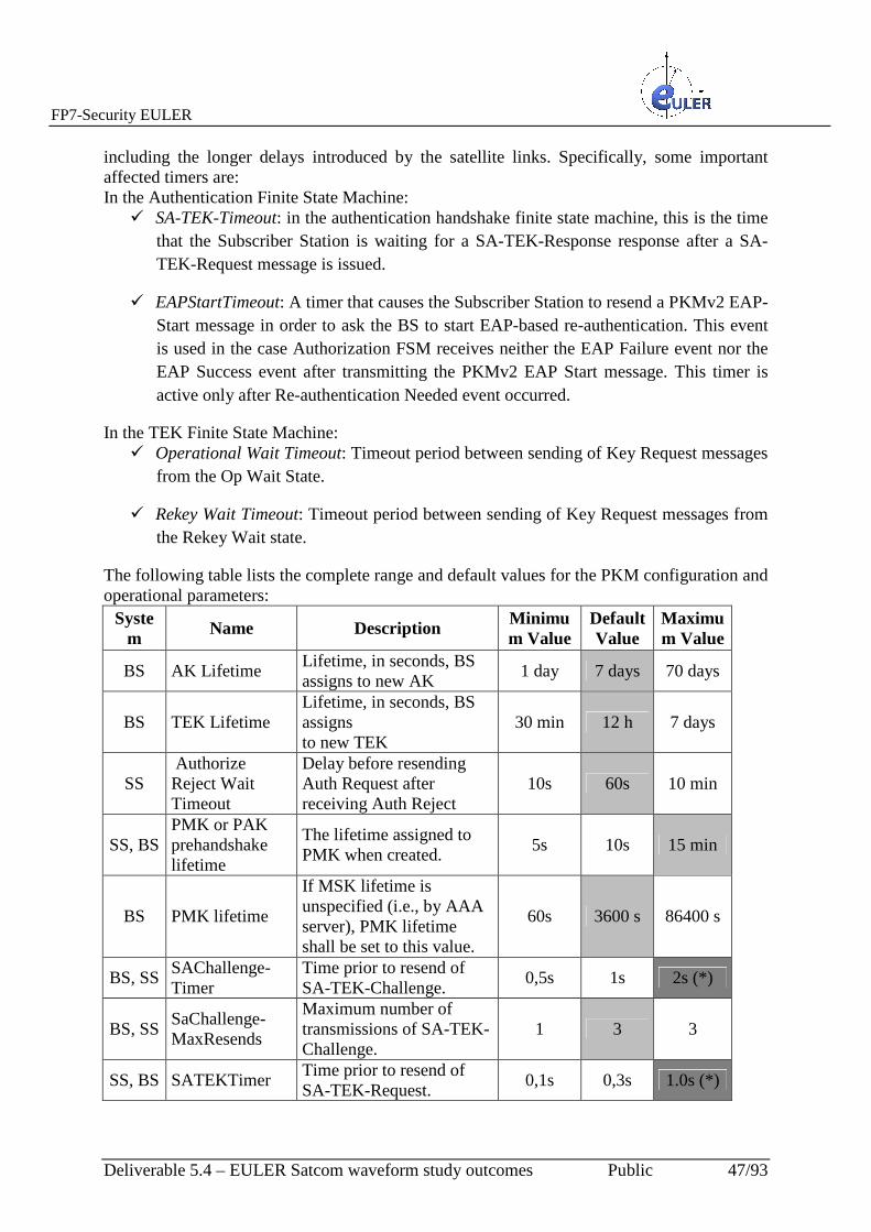
FP7-Security EULER
Deliverable 5.4 – EULER Satcom waveform study outcomes Public 47/93
including the longer delays introduced by the satellite links. Specifically, some important affected timers are: In the Authentication Finite State Machine:
� SA-TEK-Timeout: in the authentication handshake finite state machine, this is the time that the Subscriber Station is waiting for a SA-TEK-Response response after a SA-TEK-Request message is issued.
� EAPStartTimeout: A timer that causes the Subscriber Station to resend a PKMv2 EAP-Start message in order to ask the BS to start EAP-based re-authentication. This event is used in the case Authorization FSM receives neither the EAP Failure event nor the EAP Success event after transmitting the PKMv2 EAP Start message. This timer is active only after Re-authentication Needed event occurred.
In the TEK Finite State Machine: � Operational Wait Timeout: Timeout period between sending of Key Request messages
from the Op Wait State.
� Rekey Wait Timeout: Timeout period between sending of Key Request messages from the Rekey Wait state.
The following table lists the complete range and default values for the PKM configuration and operational parameters:
System
Name Description Minimum Value
Default Value
Maximum Value
BS AK Lifetime Lifetime, in seconds, BS assigns to new AK
1 day 7 days 70 days
BS TEK Lifetime Lifetime, in seconds, BS assigns to new TEK
30 min 12 h 7 days
SS Authorize Reject Wait Timeout
Delay before resending Auth Request after receiving Auth Reject
10s 60s 10 min
SS, BS PMK or PAK prehandshake lifetime
The lifetime assigned to PMK when created.
5s 10s 15 min
BS PMK lifetime
If MSK lifetime is unspecified (i.e., by AAA server), PMK lifetime shall be set to this value.
60s 3600 s 86400 s
BS, SS SAChallenge-Timer
Time prior to resend of SA-TEK-Challenge.
0,5s 1s 2s (*)
BS, SS SaChallenge-MaxResends
Maximum number of transmissions of SA-TEK-Challenge.
1 3 3
SS, BS SATEKTimer Time prior to resend of SA-TEK-Request.
0,1s 0,3s 1.0s (*)
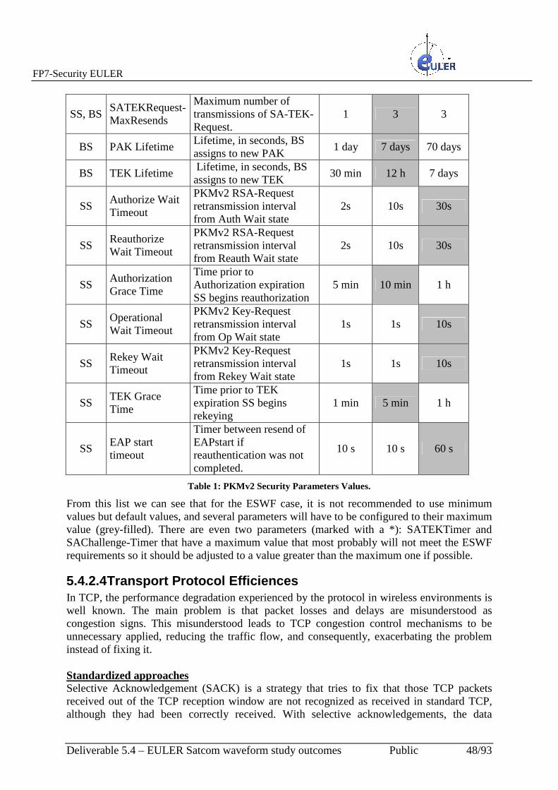
FP7-Security EULER
Deliverable 5.4 – EULER Satcom waveform study outcomes Public 48/93
SS, BS SATEKRequest-MaxResends
Maximum number of transmissions of SA-TEK-Request.
1 3 3
BS PAK Lifetime Lifetime, in seconds, BS assigns to new PAK
1 day 7 days 70 days
BS TEK Lifetime Lifetime, in seconds, BS assigns to new TEK
30 min 12 h 7 days
SS Authorize Wait Timeout
PKMv2 RSA-Request retransmission interval from Auth Wait state
2s 10s 30s
SS Reauthorize Wait Timeout
PKMv2 RSA-Request retransmission interval from Reauth Wait state
2s 10s 30s
SS Authorization Grace Time
Time prior to Authorization expiration SS begins reauthorization
5 min 10 min 1 h
SS Operational Wait Timeout
PKMv2 Key-Request retransmission interval from Op Wait state
1s 1s 10s
SS Rekey Wait Timeout
PKMv2 Key-Request retransmission interval from Rekey Wait state
1s 1s 10s
SS TEK Grace Time
Time prior to TEK expiration SS begins rekeying
1 min 5 min 1 h
SS EAP start timeout
Timer between resend of EAPstart if reauthentication was not completed.
10 s 10 s 60 s
Table 1: PKMv2 Security Parameters Values.
From this list we can see that for the ESWF case, it is not recommended to use minimum values but default values, and several parameters will have to be configured to their maximum value (grey-filled). There are even two parameters (marked with a *): SATEKTimer and SAChallenge-Timer that have a maximum value that most probably will not meet the ESWF requirements so it should be adjusted to a value greater than the maximum one if possible.
5.4.2.4 Transport Protocol Efficiences In TCP, the performance degradation experienced by the protocol in wireless environments is well known. The main problem is that packet losses and delays are misunderstood as congestion signs. This misunderstood leads to TCP congestion control mechanisms to be unnecessary applied, reducing the traffic flow, and consequently, exacerbating the problem instead of fixing it. Standardized approaches Selective Acknowledgement (SACK) is a strategy that tries to fix that those TCP packets received out of the TCP reception window are not recognized as received in standard TCP, although they had been correctly received. With selective acknowledgements, the data

FP7-Security EULER
Deliverable 5.4 – EULER Satcom waveform study outcomes Public 49/93
receiver can inform the sender about all successfully received segments, allowing the sender to retransmit only lost segments. SACK extension makes use of two TCP options: the first one is to enable “SACK-permitted” option, which may be sent in a SYN segment in order to indicate that the SACK option can be used once the connection is established. The second option is the SACK option itself, which is included in a segment from the TCP level that is receiving data to the TCP level that is sending. Another possible solution is Random Early Detection (RED), an algorithm that aims to prevent congestion by ensuring that the queue is not full, constantly calculating the average queue length and comparing it with maximum and minimum thresholds. If it is below the minimum, packets are not blocked. If it is above the maximum, all new packets will be blocked. While it is between the minimum and the maximum threshold, packets will be blocked with a probability proportional to the average size of the queue, blocking more packets as the average size approaches the maximum threshold. The more bandwidth a connection consumes, the higher is the probability of dropping packets. Slow-Start is another suitable solution. It establishes that the rate at which new packets are injected into the network should be the same at which the acknowledgements are sent from the receiver. Slow-Start adds another window to the sender TCP level: a congestion window called “cwnd”. When a new connection is established with a node on another network, the congestion window is initialized to one segment. Each time an ACK is received, the congestion window is increased by one segment. The sender can transmit over the minimum of the congestion window and the receiver’s window. The congestion window is a flow control imposed by the sender, while the receiver’s window is a control mechanism used by the receiver. The first one is based on the sender evaluation of the network congestion perception. The second one is related to the available buffer size of the receiver for that connection. The sender starts transmitting one segment and waits for an ACK. When the ACK is received, the window is increased by one, allowing two segments to be sent. When these two segments are acknowledged, the window is increased by two. This provides an exponential growth. TCP-based approaches The following table summarizes the main approaches based on mechanisms of the TCP Protocol, with their behaviour in some common situations:

FP7-Security EULER
Deliverable 5.4 – EULER Satcom waveform study outcomes Public 50/93
TCP-F TCP-ELFN TCP-BuS ATCP Split-TCP
Packet loss due to BER or collision
Same as TCP Same as TCP Same as TCP Retransmits lost packets without invoking congestion control
Same as TCP
Route failures Route Failure Notification (RFN) is sent and sender status is changed to snooze
Explicit Link Failure Notification (ELFN) is sent to the TCP sender and the state is changed to standby
Explicit Route Disconnection Notification (ERDN) is sent to the TCP sender and the state is changed to snooze
ICMP DUR message is sent to the TCP sender and ATCP state is changed to persistent
Same as TCP
Disordered packets
Same as TCP Same as TCP Disordered packets arriving after a recovery path are managed
ATCP reorders packets and hence TCP avoids sending duplicates
Same as TCP
Congestion Same as TCP Same as TCP Explicit messages such as turning off ICMP source
Early Congestion Notification (ECN) is used to inform the TCP sender. Congestion control is the same as TCP
Since the connection is divided, the congestion control is handled within an area of proxy nodes
Congestion window after route recovery
Same as before the route was lost
Same as before the route was lost
Same as before the route was lost
Recalculated for the new route
Proxy nodes keep the congestion window and manage congestion
Route failure explicit notification
Yes Yes Yes Yes No
Route recovery explicit notification
Yes No Yes No No
Routing protocol dependence
Yes Yes Yes Yes No
End to end semantics
Yes Yes Yes Yes No
Packet buffer in intermediate nodes
No No Yes No Yes
Evaluation Emulation; No routing protocol considered
Simulation Simulation Experimental; No routing protocol considered
Table 2: TCP-based approaches.
End to End approaches These solutions do not require network support. TCP endpoints are able to detect the network status by performing measurements. For example, if a large number of packets out of sequence are observed, it can be interpreted as a route change. Fixed RTO mechanism employs a heuristic to distinguish between route failures and congestion without feedback from intermediate nodes. When the timer expires consecutively, this is interpreted as a route failure. ACK-pending packets are retransmitted but the RTO remains fixed until the route is restored and that retransmitted packet is acknowledged. Another end to end solution is TCP-DOOR (Detection of Out-Of-Order and Response), which provides better TCP performance by detecting out of sequence packets indicating a route failure and preventing congestion control mechanisms to be applied in such situations. ADTCP is an end to end solution based on the use of several metrics to detect different network states: congestion, route changes and losses. These metrics are updated as packets

FP7-Security EULER
Deliverable 5.4 – EULER Satcom waveform study outcomes Public 51/93
arrive at the receiver, which estimates the state of the network and sends such information in the ACKs, allowing the sender to take appropriate actions. Satellite-based approaches The first of satellite-based approaches is TCP-STAR, which improves both performance and adaptability of network conditions on a satellite IP connection. TCP-STAR provides three mechanisms:
� CWS (Congestion Window Setting), based on the available bandwidth, avoids the decrease of transmission rate when the data loss is caused by bit error.
� LWC (Lift Window Control) rapidly increases the congestion window based in the estimated bandwidth.
� AEN (Acknowledgement Error Notification) can avoid reducing the throughput due to data retransmission, which was caused by loss or acknowledgments delays.
There is another proposal, which tries to combine TCP-Fusion with the TCP-STAR approach in order to achieve a better optimization of the satellite links. Another proposed solution for satellites is DSACK or Dynamic SACK, based on SACK (as seen previously). DSACK is a dynamic congestion control mechanism for a proxy service over a satellite network, using TCP shared connections. This mechanism can be implemented with a simple extension of the standard TCP implementations. The main objective of DSACK is to separate the TCP flow control mechanism and the error recovery mechanism while reducing the congestion control delay. Following the TCP SACK standard, DSACK uses the SACK option field to increase the loss recovery capabilities. It also uses the scale window option in order to overcome the window size limitation and improve the throughput across satellite links. The delay caused by the congestion control is reduced by means of a congestion feedback immediate mechanism that takes advantage of bottleneck knowledge in the sender and in the TCP virtual source of satellite gateways, incorporating PEP (performance enhancement proxy) solutions. As a result, this latter method, DSACK, seems to be the most adequate for the ESWF requirements, since it gets an almost immediate feedback from the lower level, with a quick detection of a possible congestion and allowing to distinguish losses due to channel errors or caused by the congestion.
5.4.3 MAC Layer
5.4.3.1 ARQ support in ESWF The ARQ mechanism is not recommended for its usage in high-delay channels and/or high error probability channels, due to the degradation of performance it implies. Instead, it should be used FEC (Forward Error Correction) strategies, including powerful error-correcting codes, or hybrid-ARQ, with a combination of FEC and ARQ strategies which at least may decrease the number of retransmissions and hence, the performance of the system in term of efficiency. But as one of the requirements of this waveform (EWFReq 8, as listed in D5.2) is that the waveform should support the 802.16e ARQ mechanism when using Best Effort scheduling,

FP7-Security EULER
Deliverable 5.4 – EULER Satcom waveform study outcomes Public 52/93
this subsection includes the study of the applicability of these mechanisms to the ESWF. It should be noted that the degradation of performance that ARQ introduces in high delay/error channels does not allow its application for other types of scheduling different to the Best Effort. ARQ in 802.16e Description The basic behaviour of ARQ is illustrated in Figure 29: if the initial transmission of an ARQ block fails, there will be a retransmission with or without rearrangement of the ARQ blocks. If there is no rearrangement, the retransmission will keep the packing and fragmentation used in the initial transmission. If there is rearrangement, an ARQ block can be fragmented in a sequence of several ARQ sub-blocks with a specific serial number for the sub-blocks (SSN: Subblock Serial Number).
Figure 29: Initial transmission and retransmission of ARQ blocks.
ARQ is configured with a set of parameters, including the following ones: • ARQ_SN_MODULUS: the number of unique sequence numbers in ARQ • ARQ_WINDOW_SIZE: The maximum size of the ARQ sliding Windows, i.e. the
maximum number of ARQ blocks with consecutive BSN that can be stored in the transmitter and receiver buffers.
• ARQ_BLOCK_LIFETIME: the maximum time that an ARQ block is managed by the ARQ Finite State Machine, once that the initial transmission has occurred. After this time, the block is discarded by the transmitter.
• ARQ_RETRY_TIMEOUT: minimum time interval a transmitter shall wait before retransmission of an unacknowledged block for retransmission. It is the sum of TRANSMITTER_DELAY and RECEIVER_DELAY, being:

FP7-Security EULER
Deliverable 5.4 – EULER Satcom waveform study outcomes Public 53/93
o TRANSMITTER_DELAY: total transmitter delay, including sending (MAC PDUs) and receiving (ARQ feedback) delays and other implementation-specific processing delays.
o RECEIVER: total receiver delay, including receiving (MAC PDUs) and sending (ARQ feedback) delays and other implementation-specific processing delays.
• ARQ_RX_PURGE_TIMEOUT: time interval for a receiver to wait after successful reception of a block without advancing his window starting point.
• ARQ_SYNC_LOSS_TIMEOUT: maximum time interval that a window starting point remains constant when data transfer is active
These are the parameters that should be configured for adapting the ARQ mechanism to a high delay/high error probability channel. ARQ Parameters Values Parameter Possible Values Recommended Values
for ESWF ARQ_BLOCK_LIFETIME 0 = Infinite
1-6553500 µs (100 µs granularity)
0
ARQ_RETRY_TIMEOUT TRANSMITTER_DELAY 0-6553500 µs (100 µs granularity) RECEIVER_DELAY 0-6553500 µs (100 µs granularity
Maximum Value
ARQ_RX_PURGE_TIMEOUT 0 = Infinite 1-6553500 µs (100 µs granularity)
Maximum Value
ARQ_SYNC_LOSS_TIMEOUT 0 = Infinite 1-6553500 µs (100 µs granularity)
Maximum Value
Table 3: ARQ Configuration Values
5.4.4 ESWF Support Services QoS is supported in WiMAX within the MAC layer. Hard QoS control is achieved by means of a connection-oriented MAC architecture, where all the downstream and upstream connections are controlled from the BS in charge. Before performing any transmission, the BS and the MS establish a unidirectional logical link called a connection between the MAC level peers. Each connection is identified by a CID (Connection ID), which serves as a temporary address for data transmission over the particular link. In addition, the WiMAX MAC layer defines three management connections for the user data transfer connections: basic connections, primary and secondary connections, which are used for functions such as ranging. WiMAX also defines the concept of service flow. A service flow is a unidirectional flow of packets with a particular set of QoS parameters and is defined by a SFID (Flor Service ID).

FP7-Security EULER
Deliverable 5.4 – EULER Satcom waveform study outcomes Public 54/93
The QoS parameters may include information such as traffic priority, maximum sustained traffic rate, maximum burst rate, minimum tolerable rate, type of planning, ARQ type, maximum delay, tolerated jitter, size and type of the SDU, bandwidth request mechanism, formation rules the transmission PDUs, etc. Service flows may be provided through a network management system or dynamically created through signalling mechanisms defined in the standard. The BS is responsible for transmitting the SFID and mapping of unique CIDs. Service flows may also be mapped into DiffServ code points or MPLS flow labels in order to enable end-to-end IP-based QoS. However, maximum latency and tolerated jitter are parameters of particular interest in this type of services, because the delay is usually very important in wireless networks, and particularly in satellite network, the delay is very high and should be taken into consideration. According to 802.16, the maximum latency and tolerated jitter values are shown in the following table:
Table 4: Maximum latency and tolerated jitter values in 802.16e.
So, the next subsections describe the main support services included in ESWF and how they are affected by the different parameters. It is important to note that for those services depending on the tolerated jitter and maximum latency, the values of these parameters cannot be less than 5000ms. This implies that these services will be only supported for tolerated jitter and maximum delay of 5 and 10 seconds. Unsolicited grant service (UGS) This service is designed to support data packets of fixed size at constant bit rate (CBR). The following parameters are considered mandatory, and those marked in bold parameters are especially affected by the longer delay of the satellite channel:
• Tolerated Jitter • SDU Size • Minimum reserved traffic rate • Maximum Latency • Request and Transmission Policy
This service is designed for support flows of real-time services that generate data packets of fixed size every certain period, such as VoIP. UGS offers concessions of fixed size in real time and does not need an explicit bandwidth requirement by the subscriber station, thus eliminating the overhead and associated latency with the bandwidth request.

FP7-Security EULER
Deliverable 5.4 – EULER Satcom waveform study outcomes Public 55/93
Real-time variable-rate (RT-VR) service This service is designed for supporting real-time service flows, such as MPEG video, that generate data packets of variable size every certain period. The following parameters are considered mandatory, and those marked in bold parameters are especially affected by the longer delay of the satellite channel:
• Minimum reserved traffic rate • Maximum sustained traffic rate • Maximum Latency • Request and Transmission Policy • Traffic Priority
In this kind of service, the BS provides unicast polling opportunities for the MSs that require bandwidth. These opportunities are quite frequently to ensure that latency requirements of real-time services are achieved. This service involves more overhead than UGS requests but is more efficient for services that generate data packets of variable size or have a cycle or duty factor lower than 100%. Non-Real-time variable-rate (NRT-VR) service This service is designed to support delay-tolerant data flows, such as FTP, that require transmissions of data of variable size at a minimum guaranteed rate. Following parameters are considered mandatory and are not affected by the delay:
• Minimum reserved traffic rate • Maximum sustained traffic rate • Request and Transmission Policy • Traffic Priority
This service is similar to the previous one except that the MS may also perform polls based on contention in the uplink for requesting bandwidth. It allows unicast polling opportunities, but the average duration between two opportunities is in the order of few seconds, which is higher than the real-time service. All MSs of a certain group may require resources during one of these opportunities, which may result in collisions and additional attempts. Best Effort (BE) Service Best Effort service is designed to support data streams, such as web browsing. This service does not require any minimum service level guarantees. Following parameters are considered mandatory and are not affected by the delay:
• Maximum sustained traffic rate • Request and Transmission Policy • Traffic Priority
This service provides a very low support for QoS and it should be only applied for services that do not have any strict QoS requirements. The data is sent when resources are available and do not require any kind of service planning. The MS uses the poll opportunity based on contention for bandwidth request. External Real-time variable-rate (ERT-VR) service

FP7-Security EULER
Deliverable 5.4 – EULER Satcom waveform study outcomes Public 56/93
Also referred to as extended real time polling-service (ErtPS), this service is designed for supporting real-time applications such as VoIP with silence suppression, which have variable data rates but requires guaranteed data rate and delay. This service is only defined in IEEE 801.16e-2005. The following parameters are considered mandatory, and those marked in bold parameters are especially affected by the longer delay of the satellite channel:
• Minimum reserved traffic rate • Maximum sustained traffic rate • Maximum Latency • Tolerated Jitter • Request and Transmission Policy • Traffic Priority
5.5 ESWF Requirements Specification This section lists the needed modification from the original requirement of the EWF profile.
5.5.1 Physical Layer Identified changes in the EWF:
� EWFReq 13:
o Dupplexing mode: HFDD
� EWFReq 14:
o Cell radius: This parameter should be fixed as a maximum differential delay (e.g. 20ms)
� EWFReq 10/11/12/25:
o Initial and periodic ranging procedures should be modified by selecting a larger ranging window.
� EWFReq 20/21:
o The overall gross-throughputs should be reduced depending on the maximum differential delay.
� EWFReq 29:
o A cell is now a beam spot. Mobility should be verified if the maximum differential delay increases with the mobility.
5.5.2 Security Sublayer Identified changes in the EWF:
� EWFReq 23/27/34/39/49:

FP7-Security EULER
Deliverable 5.4 – EULER Satcom waveform study outcomes Public 57/93
o The PKMv2 configuration and operation parameters should be adjusted according to Table 1 in section 5.4.2.3. The recommended values are:
� AK Lifetime: 7 days
� TEK Lifetime: 12 hours
� Authorize Reject Wait Timeout: 60 secs
� PMK or PAK prehandshake lifetime: 15 minutes
� PMK lifetime: 3600 sec
� SAChallenge-Timer: 10 secs (larger than the maximum value: 2 secs)
� SaChallenge-MaxResends: 3
� SATEKTimer : 6 secs (larger than the maximum value: 1 secs)
� SATEKRequest-MaxResends: 3
� PAK Lifetime: 7 days
� TEK Lifetime: 12 hours
� Authorize Wait Timeout: 30 secs
� Reauthorize Wait Timeout: 30 secs.
� Authorization Grace Time: 10 minutes
� Operational Wait Timeout: 10 secs.
� Rekey Wait Timeout: 10 secs.
� TEK Grace Time: 5 minutes.
� EAP start timeout: 60 secs.
o There will be two parameters according to that table that should be configured to values greater than the maximum allowed.
o The TCP implementation which is supporting the protocol EAP-TLS should include some of the approaches listed in section 5.4.2.4. The Dynamic SACK seems to be one of approaches that better can fit the ESWF requirements.
5.5.3 MAC Layer Identified changes in the EWF:
� EWFReq 8:

FP7-Security EULER
Deliverable 5.4 – EULER Satcom waveform study outcomes Public 58/93
o ARQ should be avoided if possible. In case of the Best Effort scheduling, the ARQ configuration values should be adjusted according to Table 3 in section 5.4.3.1.
� EWFReq 4,5, 42:
o The Unsolicited Grant Service (UGS) user traffic scheduling will only be provided with values of the maximum latency and tolerated jitter of 5 or 10 seconds.
� EWFReq 6,7, 43:
o The Extended Real Time Polling System (ErtPS) user traffic scheduling will only be provided with values of the maximum latency and tolerated jitter of 5 or 10 seconds.
FP7-Security EULER
Deliverable 5.4 – EULER Satcom waveform study outcomes Public 59/93
6 Simulations Assessment This Section reports a first preliminary analysis which shows how the proposed satellite OFDMA system can be more efficient and flexible than traditional satellite systems (DBV-RCS and DVB-S2). We assume that OFDMA scheduler of the uplink resources resides at the HUB and that it is able to synchronize the downlink and uplink frames according to the methods/procedures described in the previous sections. The typical scenario, which is under study is based on the classical approach based on very small aperture terminals (VSATs). The typical network is defined to be applicable for dedicated users, who have the privilege to have an exclusive use of the satellite bandwidth dedicated to them. It is important to consider in the application scenario that the user does not have a fixed defined configuration, but on the contrary the wideness of the applications of the satellite network is considered a plus, because it allows to optimise during the network life the satellite bandwidth utilisation minimising the operational costs. As a reference case it will be considered the case of GEO satellites, the ku-band frequency band using an EUROBIRD Class satellite. It is important to verify with respect to traditional systems how the proposed one can improve the use of the satellite transponder bandwidth both for the efficiency (assuming as a reference KPI the bps/Hz ratio) and for the variety of applications, which the system can support. Considerations will be made on
• EIRP, G/T, transponder Gain • Network architecture: mesh or star • Multiple access technique • FEC, modulation and multiplexing schemes.
6.1 System Description and Network Architecture The typical satellite system is based nowadays on a DVB-RCS configuration. The latest generation allow to manage with the same network a meshed and a star one. In this case the Hub is on one side acting as a Master station and on the other one as an Access Point. The transponder is assumed to work in the linear zone, which implies to reduce the total transmitted EIRP of 4, 5 dB. The proposed system is based on an evolution of the terrestrial Wimax technology adapted to the satellite network constraints. The description is comparing the differences between the two technologies on the performance, flexibility in use In the network architecture for both technologies the following communications links are identified:

FP7-Security EULER
Deliverable 5.4 – EULER Satcom waveform study outcomes Public 60/93
• From the Hub to VSAT: Outbound link (including the outbound uplink and the outbound downlink), for this type of link it is assumed to utilize a TDM stream for DVB-RCS and an OFDM stream for Satellite Wimax like.
• From the VSATs to the Hub: Inbound link (including the inbound uplink and the inbound downlink), for this type of link it is assumed to utilize Multi Frequency TDMA stream for the DVB-RCS and OFDMA stream for Satellite Wimax like.
• From VSATs to VSATs: Direct link (including the direct uplink and the direct downlink), for this type of link it is assumed to utilize one Multi Frequency TDMA stream (used as a SCPC) for DVB-RCS and again OFDMA (without any limitation) for Satellite Wimax Like.
Figure 30 shows the network architecture for the three types of links.
Figure 30: Network Architecture with three types of links: Forward, Return and and one-to-one.
6.2 GEO Satellite The choice of the satellite is taken as a typical example among a wide possibility of similar ones (depending on the effective coverage areas and services to be delivered). In any case the criteria to be taken into account are based on:
• Position of satellite on the geostationary orbit and beam coverage. • Available Bandwidth according to the needs of the users and the availability of the
satellite (C, Ku, Ka). • Transponder Bandwidth of satellite.

FP7-Security EULER
Deliverable 5.4 – EULER Satcom waveform study outcomes Public 61/93
• Overall cost of the network, of the satellite.
6.3 European Coverage of satellite system This work aims to have a wide area of applicability, therefore the selection of the satellite
system has been chosen to cover Europe and the Mediterranean area, without forcing the
dimension of the antenna dishes to be a minimum. This implies that solutions described could
have further optimisation, if required using better transponder performance.
The analysis has been carried out for Ku band, but the validity of the conclusions could be
extended to other frequency bands such as C and Ka.
6.4 Transponder Bandwidth Typically a network will not require the full transponder bandwidth occupation, but just a
small portion of it, as a consequence it very important to define the complete set of parameters
which optimise the ratio between the useful information data rate and the occupied
bandwidth, including coding, modulation scheme, the link implementation margin and the
Energy over bit required to satisfy the BER requirement.
The satellite used for the analysis is a recent one called W2 A launched in 2009 and is
operated at 10° East within +/- 0.08°E/W and +/- 0.05° N/S. It provides 24 channels with a
minimum operational lifetime of more than 12 years Geo-stationary orbit.
The main characteristics of the proposed transponder are shown in Table 5:
Satellite
Number of
Transponders
Longitude
Transponder
Bandwidth
MHz
Minimum in the
European and
Med-area
G/T dB/K
Minimum in the
European and
Med-area
EIRP dBW
W2 46 10o E 36 and 72 3 46
Table 5: W2 Satellite Ku band Transponder Characteristics.
The satellite EIRP is shown in Figure 31. It is assumed that the coverage limit is about 46
dBW, covering Europe and the North African coast.
The corresponding G/T is about 4 dB/k in the same area assuming a system Noise temperature
in clear sky conditions of about 600 K. It is assumed to have the possibility to define the
Transponder Gain according to the optimisation need (with step of 1 dB in a range of 15 dB).

FP7-Security EULER
Deliverable 5.4 – EULER Satcom waveform study outcomes Public 62/93
Figure 31: EIRP Contours Ku band W2 satellite.
6.5 Multiple Access techniques It is assumed to have the possibility of selecting the multiple access technique used in earth
stations to communicate with each other assuming that the transponder can be loaded with
carriers in a way that satellite systems can operate with no risk of collision and conflict among
the different stations accessing the satellite transponder.
Two techniques are considered, the former based on the well known standard DVBs 2plus
RCS and the latter based on the adaptation of OFDM-OFDMA from the Wireless
communications to the Satellite ones.
6.5.1 Demand Assignment Multiple Access It is assumed to have the possibility of using Demand Assignment Multiple Access (DAMA).
This assumption implies the authorisation for transmitting from the station. In case the most
of the traffic is between the Hub station and the VSAT the DAMA procedure is rather simple.
That is the case of the present DVB-RCS system architecture and is assumed to be valid for
this analysis.

FP7-Security EULER
Deliverable 5.4 – EULER Satcom waveform study outcomes Public 63/93
6.5.2 DVBS2-RCS for Mesh and Star networks The forward link between the hub and the satellite station or satellite interface terminal (SIT)
uses the DVBS and DVBS2 standard. The DVB-S forward channel is a QPSK modulated
TDM broadcast channel (it can work up to 16 APM or as a BPSK for hard rain). Similar to
any other satellite forward links the data of all SIT is aggregated in a single TDM carrier.
The IP packets are encapsulated in a MPEG-2 transport steam (MPEG-2 TS) by means of an
encapsulation protocol named Multiprotocol Encapsulation (MPE) or the new proposed
Unidirectional Lightweight Encapsulation (ULE).
The receiver station needs a DVBS receiver card and a software capable of extracting the IP
packets out of the MPEG-2 stream (typically a Linux-based system).
The return channel uses another standard, based on point to point. The return channel uses
QPSK and MF-TDMA (Multi Frequency Time Division Multiple Access).
The SITs are capable of sending data in multiple carriers (Multi frequency) and in certain time
slots. Considering the advantages of this architecture with respect to the classical SCPC one
it is under advanced development a new DVBS and DVB-S2 meshed Architecture working
with Transparent transponders.
DVB-S2/RCS Transparent Mesh Architecture is a new mesh overlay architecture for
combined star (access) and mesh networking.
The mesh air interface utilises same RCS return link transmission and the RCS Hub station
for RCS signalling, synchronisation and mesh connection control /bandwidth allocation.
The RCS terminals shall be equipped with mesh demodulator for full mesh capability based
on Connection Control protocol (C2P), which is under standardisation process.
6.5.3 OFDM-OFDMA As described in the previous sections, the Orthogonal frequency-division multiplexing
(OFDM), defined sometimes as coded OFDM (COFDM) and discrete multi-tone modulation
(DMT), is a frequency-division multiplexing (FDM) scheme used as a digital multi-carrier
modulation method.
A large number of closely-spaced orthogonal sub-carriers are used to carry data. The data are
divided into several parallel data streams or channels, one for each sub-carrier. Each sub-

FP7-Security EULER
Deliverable 5.4 – EULER Satcom waveform study outcomes Public 64/93
carrier is modulated with a conventional modulation scheme (from BPSK to 32 APM) at a
low symbol rate, maintaining total data rates similar to conventional single-carrier modulation
schemes in the same bandwidth with the additional advantage of no need to use the so called
roll-off factor (see Figure 32).
Figure 32:OFDM frequency Channel example.
OFDM has developed into a scheme for wideband digital communication, whether wireless or
over copper wires, used in applications such as digital television and audio broadcasting,
wireless networking and broadband internet access.
The primary advantage of OFDM over single-carrier schemes is its ability to cope with severe
channel conditions for terrestrial applications (for example, attenuation of high frequencies in
a long copper wire, narrowband interference and frequency-selective fading due to multipath)
without complex equalization filters. Channel equalization is simplified because OFDM may
be viewed as using many slowly-modulated narrowband signals rather than one rapidly-
modulated wideband signal.
The low symbol rate makes the use of a guard interval between symbols affordable, making it
possible to handle time-spreading and eliminate inter-symbol interference (ISI). This
mechanism also facilitates the design of single frequency networks (SFNs), where several
adjacent transmitters send the same signal simultaneously at the same frequency, as the

FP7-Security EULER
Deliverable 5.4 – EULER Satcom waveform study outcomes Public 65/93
signals from multiple distant transmitters may be combined constructively, rather than
interfering as would typically occur in a traditional single-carrier system.
In the case of satellite communications the channel is essentially defined by the thermal noise
and therefore the advantage in using the OFDM scheme is strictly linked to the possibility to
assign the frequency channel to different stations in a quite simple way, increasing the
spectral efficiency with respect to traditional system in presence of an increase of criticity of
the down link.
Figure 33:OFDMA Frame structure example according to IEEE 802.16 TDD mode.

FP7-Security EULER
Deliverable 5.4 – EULER Satcom waveform study outcomes Public 66/93
Therefore for satellite applications it has to be considered the Orthogonal Frequency-
Division Multiple Access (OFDMA), which is a multi-user version of OFDM Multiple access
is achieved in OFDMA by assigning subsets of subcarriers to individual user. This allows
simultaneous low data rate transmission from several users (see Figure 33).
Clearly this methodology allows flexibility of deployment across various frequency bands
with little needed modification to the air interface, averaging interferences from neighbouring
cells, by using different basic carrier permutations between users in different cells.
Interferences within the cell are averaged by using allocation with cyclic permutations.
It has to be noted that the system has a higher sensitivity to frequency offsets and phase noise.
In the case of satellite OFDMA does not lose the OFDM diversity gain, and resistance to
frequency-selective fading, if very few sub-carriers are assigned to each user, and if the same
carrier is used in every OFDM symbol.
Code division multiplexing (CDM), typically used from the Hub and Code division multiple
access (CDMA), typically used from the users, are schemes in which a number of users can
occupy all of the transponder bandwidth all the time.
CDM and CDMA signals are encoded such that information from an individual transmitter
can be recovered by a receiving station that knows the code being used in the presence of all
the other CDMA signals in the same bandwidth which provides a decentralised satellite
network, as only the pairs of earth stations that are communicating need to coordinate their
transmissions regarding to transponder power limitations and the practical constraints of the
codes in use.
This techniques can be combined very usefully with OFDM and OFDMA techniques, when
very low bit rates are needed and the usable antennas are very small (a few wavelengths),
such as in the case of sensor network.

FP7-Security EULER
Deliverable 5.4 – EULER Satcom waveform study outcomes Public 67/93
6.6 Coding Correction Techniques All the recent transmission systems developed for improving the spectrum efficiency and
approaching the Shannon limit are based on new coding methodology, which are very
powerful and efficient.
In order to make a realistic analysis of the proposed system it has been assumed to use a
number of turbo code taken from the literature and presented in Table 6.
Table 6: Eb/N0 at 10-6 BER using Turbo Code (after Comtech).
In order to have realistic data from the analysis minimum values of the Code gain have been
considered.

FP7-Security EULER
Deliverable 5.4 – EULER Satcom waveform study outcomes Public 68/93
6.7 Modulation Techniques Modulation techniques allow band-pass transmission of digital data for satellite links.
These techniques are based on Phase Shift Keying (PSK) typically 2 (BPSK), 4 (QPSK), 8
(8PSK) and since a few years also 16 (16 PAM), but in this case Amplitude and Modulation
are used. Modulation can be selected to optimise Eb/N0 ratio.
Modulation techniques are foreseen in both DVB and OFDM techniques, they include a
number of features such as scrambler (see Figure 34).
Figure 34: Eb/N0 for different modulation and correcting code schemes.

FP7-Security EULER
Deliverable 5.4 – EULER Satcom waveform study outcomes Public 69/93
6.8 Spectral Efficiency The bandwidth is a key parameter of the system, the spectral efficiency which is the ratio
between the bit-rate and the band (measured bps/Hz) is of course depending also on the
available EIRP at the transponder level.
The relation between the bandwidth W and the bit rate R is given by the following
relationship:
and the spectral efficiency ηηηη
6.9 Link Analysis Parameters
6.9.1 Eb/N0, BER assumed for the analysis It is assumed as a reference value for Eb/N0 the figure better than 9,9 dB, which is the un-
coded value in the case of BPSK and QPSK modulations corresponding to 10-5 error
probability. In addition to this figure it has been considered the coding gain, the loss relative
to the type of modulation with respect to the BPSK-QPSK one and the implementation
margin.
Where
R=bit rate
RS=symbol rate=bit rate R/N, N is the number of bit per symbol
αααα=roll off factor (between 0 and 1,(typically between 0,2 and 0,5 for DVB and 0 for OFDM)
ββββ=filter efficiency factor: (additional margin to minimise adjacent carrier interference, typically 0,02 for DVB and
0 for OFDM)
k=ratio between coded signal and un-coded signal
As an example using N=2 (QPSK) RS=R/2 k=2, αααα=0,2 and ββββ=0,02, the spectral efficiency results=1,6 bps/Hz.
Rk (1+αααα)(1+ββββ)
N
W=
W = kRS (1+αααα)(1+ββββ) =kR(1+αααα)(1+ββββ)
N
η η η η =R
k (1+αααα)(1+ββββ)N
W=
Rk (1+αααα)(1+ββββ)
N
W=
W = kRS (1+αααα)(1+ββββ) =kR(1+αααα)(1+ββββ)
NW = kRS (1+αααα)(1+ββββ) =
kR(1+αααα)(1+ββββ)
N
η η η η =

FP7-Security EULER
Deliverable 5.4 – EULER Satcom waveform study outcomes Public 70/93
6.9.2 System Parameters (Clear Sky) In Table 7 the main synthetic parameters used for the analysis are shown. About the
additional noise to the thermal one there have been considered the following ones:
• Inter-modulation noise at each Amplifier level (Earth and Satellite), when applicable
based on the effective Output back off present in the equipment.
• Non linearity Noise taken into account essentially for OFDM-OFDMA modulation
techniques at the Satellite level (ratio between signal and Noise =22 dB)
• Implementation Margin equal to 1,5 dB for the Hub, 2 dB for the VSAT either STAR
or MESH configured.
In order to consider an equivalent Eb/N0 value the degradation due to large modulation
constellation has been considered (from literature) as follow.
• BPSK and QPSK Degradation factor= 0,0 dB
• 8-PSK Degradation factor= -3,6 dB
• 16-APM Degradation factor= -6,6 dB
System Characteristics
Uplink Frequency 14.5 GHz
Downlink Frequency 11.7 GHz
Range to Satellite 40000 Km
Satellite Transponder
Maximum output power 50 W
Transponder Bandwidth 72 MHz
Transponder Noise Temperature 600 K
Transmitting Antenna Gain 29,0 dBi
Receiving Antenna Gain 30,8 dBi
Transponder Gain From 140 to 155 dB

FP7-Security EULER
Deliverable 5.4 – EULER Satcom waveform study outcomes Public 71/93
VSAT Station Parameters
Transmitter Output Power 4.0 W (for STAR) 40 W (for MESH)
Antenna Dish Diameter 1,5 m (for STAR) 1,8 m (for MESH)
Antenna Aperture Efficiency 65%
Antenna Gain (Transmit) 45,3 (1,5 m) and 46.9 (for 1,8 m) dBi
Antenna Gain (Receive) 43,4 (1,5 m) and 45.0 (for 1,8 m) dBi
Receiver Noise Temperature 200 K
Hub Station Parameters
Maximum Transmit Power 150 W
Antenna Diameter 3,5 m
Antenna Aperture Efficiency 65%
Hub Antenna Gain (Transmit) 52.6 dBi
Hub Antenna Gain (Receive) 50.8 dBi
Receiver Noise Temperature 150 K
Atmospheric Losses
In Clear Air at 14.5 GHz 0.7 dB
In Clear Air at 11,7 GHz 0.5 dB
Table 7: Main System Parameters.
6.9.3 Rain Losses In Ku band it assumed to have a link availability better than 99,8% of the time corresponding
to about 3 dB on the up link and 2 dB for the down link in the case of the STAR network,
while for balanced link it is assumed to have an availability of about 99,6% corresponding to
3 and 2 dB respectively.
The additional loss produces an increase of the system temperature which has been evaluated
as about 99 K at 3 dB losses, 80 K at 2 dB losses on the up link and on the down link.
6.10 Result Summary The following figures show summary results of a simulation which compares the
performances of an OFDM-OFDMA system and the DVB-RCS according to the system
parameters described above. In all cases it is assumed to have an uplink power control system

FP7-Security EULER
Deliverable 5.4 – EULER Satcom waveform study outcomes Public 72/93
which can be on or off.
Figure 35 shows the case where an OFDM-OFDMA stream filling one 72 MHz transponder.
In this case the Spectrum efficiency assumed as a Merit Figure is about 1,15. The effective
OBO is about 5 dB. This implies that the C/N in down link is relatively small and indicates
some potential criticity to face (such as additional power control or stronger Correcting code
or decrease of the symbol rate for that specific link) in the case a double rain loss is present on
the up and the down links.
The second case (see Figure 36) shows DVB-RCS carriers filling one 72 MHz transponder
(34% DVB and 66% RCS). It is assumed rain on the Hub satellite uplink (uppc included), on
the satellite-Hub downlink and on both uplink and downlink for VSAT. In this case the
Spectrum efficiency assumed as a Merit Figure is about 0.94. the effective OBO is about 4,0
dB.
Comparing the two described cases, it is clear that the advantage of using the OFDM-
OFDMA technique over the DVB-RCS one is about 23% of increase in the bps/Hz, without
changing the features of the elements of the network.
The Hub station is delivering one Forward stream up to 12,6 Mbps (OFDM) or 5 stream (5
Mbps each) in the case of DVB.
The VSATs are delivering one Return Stream up to 614 kbps in the case of OFDMA with rain
on the up link and rain on the down link or up to 6 streams of 128 kbps (TDMA) each in the
case of RCS with the same rain conditions.
For the balanced network with rain on both the up and the down links the OFDMA streams is
708 kbps (continuously) or 4 streams of 128 kbps (TDMA) each in the case of RCS. This is
shown in Figure 37, Figure 38, Figure 39, Figure 40.
In each case the figure provides also the details of the link budget used for the analysis.

FP7-Security EULER
Deliverable 5.4 – EULER Satcom waveform study outcomes Public 73/93
Figure 35: Summary results assuming OFDM-OFDMA filling one 72 MHz Transponder Rain considered on the Hub satellite up link (uppc included), on the
satellite-Hub down link and on both up link and down link for VSAT with rain.

FP7-Security EULER
Deliverable 5.4 – EULER Satcom waveform study outcomes Public 74/93
Figure 36: Summary Results assuming DVB-RCS carriers filling one 72 MHz Transponder (34% DVB 66% RCS). Rain considered on the Hub satellite up link (uppc included), on the satellite-Hub down link and on both up link and down link for VSAT with rain.

FP7-Security EULER
Deliverable 5.4 – EULER Satcom waveform study outcomes Public 75/93
Figure 37: Forward link from Hub to VSAT including rain on the up link OFDM stream.
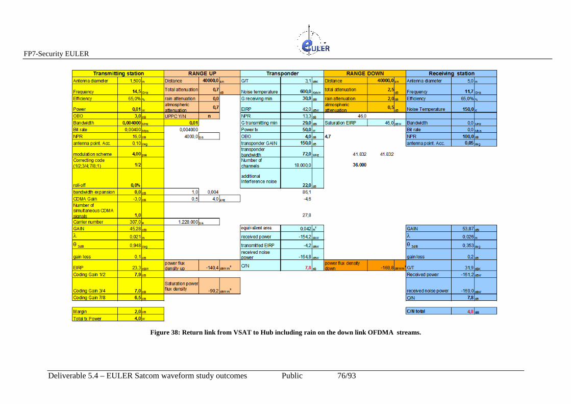
FP7-Security EULER
Deliverable 5.4 – EULER Satcom waveform study outcomes Public 76/93
Figure 38: Return link from VSAT to Hub including r ain on the down link OFDMA streams.

FP7-Security EULER
Deliverable 5.4 – EULER Satcom waveform study outcomes Public 77/93
Figure 39:Forward link from Hub to VSAT including r ain on the up link DVB stream.
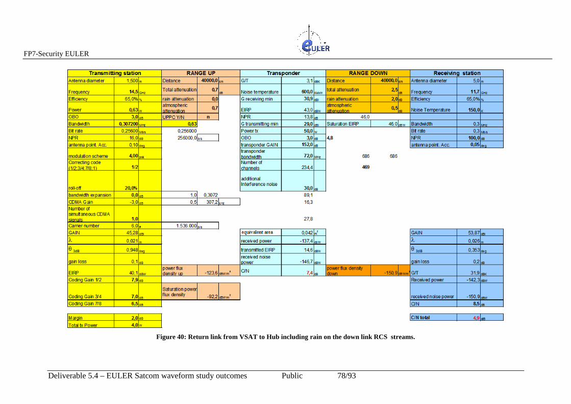
FP7-Security EULER
Deliverable 5.4 – EULER Satcom waveform study outcomes Public 78/93
Figure 40: Return link from VSAT to Hub including r ain on the down link RCS streams.

FP7-Security EULER
Deliverable 5.4 – EULER Satcom waveform study outcomes Public 79/93
7 Additional Utilisation of the OFDM-OFDMA Technique
7.1 CDM-CDMA over OFDM-OFDMA Applications The possibility of overlapping CDM-CDMA over OFDM-OFDMA technique is very
attractive. Indeed it allows to use the satellite network for data gathering, with small antennas
transmitting low data bit rate (such as wireless sensor networks), without disturbing other
services and other satellites because of the spreading (see Figure 41)
Figure 41: Combined use of the transponder as a generic VSAT service network and a sensor network.
The situation of the transponder allows to maintain different types of services with a
minimum of re-configuration needed. In fact a CDMA signal can use non contiguous CDMA
frequency channels.

FP7-Security EULER
Deliverable 5.4 – EULER Satcom waveform study outcomes Public 80/93
8 Considerations on the use of OFDM-OFDMA Technology for Satellite Applications
8.1 Considerations on the Application possibility It is well known that terrestrial networks may not work in a disaster situation, at least as a first
response; in contrast, satellite networks keep on working no matter what happens on Earth.
Satellite networks are necessary to “response and recover more efficiently and effectively
both during, and after, an incident”, but the main issue for Security and Safety operators is to
maximise the use of the transponder bandwidth during the crisis and with additional services
during standard operational periods, optimising the overall capabilities and having high
synergies with terrestrial infrastructure to reach a larger operational coverage and a more
efficient architecture to face crises and to minimise costs in managing resources.
The described satellite solution is totally in line with the present technological highlights in
the telecommunication systems and has the objectives to allow the possibility of operate with
a few satellite transponders using not only different frequency bands, but also different
modulation standards
The possibility of cooperate with a variety of terrestrial wireless networks allowing the
maximum of interoperability, based on IP standard.
8.2 Some technological highlights The satellite terminal configuration is based on a specific SW radio approach.
In this way the transmission system allows the use of a variety of waveforms available with
the present commercial transponders, plus a dedicated waveform using OFDM, OFDMA and
possibly CDM-CDMA over such a Access technique.
This approach, based upon the software defined radio standard, is capable to suit many
transmission requirement among the available ones, without changing the base band and the
IF section of the terminal, while the RF head shall be changed according to the specific RF
bandwidth.
The first application is envisaged for ku band, but easily extendable to other bandwidth such
as L, C, X, Ka, S.
This system appears to have advantages on the Transmission efficiency in having the

FP7-Security EULER
Deliverable 5.4 – EULER Satcom waveform study outcomes Public 81/93
possibility of an opportunistic use of satellite bands, dynamic use of resources, easier multiple
access, interoperability with existing satellite networks (legacy) via the development of SDR
waveforms, on the usability, but also in an ease extension to different coverage areas,
cooperation among transnational P&GS Entities.
The maintenance of the system is simplified , being based on the availability on the market of
up dated HW boards, open source SW used for Wireless systems, which can be easily adapted
to the satellite case, optimising the full life cycle, allowing to upgrade the network with new
and more efficient transmission systems and the continuous interoperability between older
and actual network elements, taking the advantages of external standardisations and
development at the interface level.
8.3 Considerations on the Software Define Radio technology The use of SDR is a strategic choice, allowing, on one side, an easier implementation of
different access modes, such as TDM-MF/TDMA, DVB-S2-RCS, OFDM-OFDMA (with
CDM-CDMA) and on the other the implementation of different modulation scheme,
according to the existing standards for multiplexing and accessing techniques, such as BPSK-
QPSK-8PSK, 16 PAM, different error correction codes (Reed-Salomon , Convolutional with
Viterbi decoder, Turbo-code)
The use of SRD allows to save HW and implementing by SW additional features, which can
be requested by Customers such as: Control channel (using for instance a L-band satellite) or
a better interoperability between the modulation part and antennas, GPS-Supported, beam
pointing, etc. As an example in Figure 42 it is shown a station architecture using SDR.
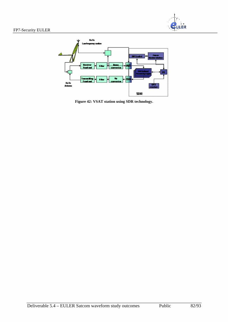
FP7-Security EULER
Deliverable 5.4 – EULER Satcom waveform study outcomes Public 82/93
Figure 42: VSAT station using SDR technology.

FP7-Security EULER
Deliverable 5.4 – EULER Satcom waveform study outcomes Public 83/93
9 Recommendation for a future Satcom WF for P&GS
9.1 Introduction This Section aims to provide some of the following:
1. Provide a basic view of security functions in view of Public and Governmental Services (P&GS) Information Assurance (IA)
2. Provide a view of IA for Satellite Communication (SATCOM) with a view on P&GS. The above will be dealt with in a sequential manner and holistically some of the elements of a solution will be generated. The importance of SATCOM to furnish communications following a disaster such as an earthquake has been widely recognised by public safety community e.g. the British Association of Public Safety Communication Officers (BAPCO) [8] reported upon the utilisation of the S-band spectrum for a handheld SATCOM version of TETRA, very similar to a pan-European version of the TerreStar System in the US, back in October 2007 [9]. This would need a very large space segment with an antenna exceeding 10 metres and a very sophisticated Complimentary Ground Control (CGC) system to enable the sharing of protectively marked information between European States and thereby manage the system optimally, i.e. to produce the appropriate spot beams and make the best use of data rates. The TerraStar Space Segment is famed for being the World’s Heaviest Satellite [10] with an 18 metre antenna and with some antenna sensitivity to enable satellite to handset communications; the image is shown in Figure 43.
Figure 43: TerreStar Coverage[10].

FP7-Security EULER
Deliverable 5.4 – EULER Satcom waveform study outcomes Public 84/93
However, whilst most attractive from an operational standpoint, predominantly due to cost since a global recession followed in the subsequent year as well as how such a complex system is to be managed, the 2 GHz spectrum to provide connectivity for the emergency services in even the most remote parts of Europe did not happen. There is an assumption that in order to have a minimum of Space Segment the use of GEOs (Geostationary Earth Orbits) may be sufficient, however the use of the other orbits e.g. Medium Earth Orbits (MEOs) and Low Earth Orbits (LEOs) or additionally Highly elliptical Earth Orbits (HEOs) could improve both the choice of frequencies and give rise to a situation to use Public Safety systems with a number of modes. Examples of such systems includes the former system, the Thuraya system discussed in [11] and [12] or the Iridium system discussed in [13]. The advantage could be to follow the Thuraya model - i.e. modify the existing terrestrial telephony standards to suit satellite (in Thuraya's case GSM to GMR and 3G to GMR-3G in our case TETRA) and then design and launch a specialized satellite such that an ostenstively normal looking handset can operate via terrestrial and via the specialised satellite. The Iridium 9505A handsets can distribute Public Safety to various Red Cross National Societies [13]. These phones were made operational within minutes of arriving in the certain Islands for use during the recent tsunami, for example, when land-based communications were unavailable. The systems allow frequency diversity: a number of addition frequencies can be included, e.g. (Very High Frequency) VHF and the use of UHF (Ultra High Frequency) in addition to the standard higher band such as those in S-band and higher, e.g. Ka-band. Therefore, both questions of cost and control fell against the benefits which may be offered by a Mobile Satellite System (MSS). As mentioned in former sections of this report, there is therefore a need for EULER to provision:
1. Communication to extant public service communications running different emergency communication systems 2. Links to a more sophisticated WaveForm (WF) such as the EWF (EULER WaveForm) to enable the capacity to be carried, i.e. that a higher aggregate data rate is therefore needed to support the various systems for which the EWF is designed 3. Support to a SATCOM node which is able to integrate a network of public safety personnel with a SATCOM node – which will therefore need to have as a minimum a data rate commensurate with the highest EWF data rate for the EULER SATCOM system to be able to support the EWF in real-time.
Figure 44 represents the scenario for a concept of employment using a satellite and with both the WiMAX WF in the EWF form and with the TETRA waveform. This scenario defines the case where a WiMAX user wishes to retrieve information held by blue-light services, e.g. biometric data off a TETRA database. Clearly, this is a situation for which the inverse does not pose a problem. That is, the circumstances of a blue-light user needing WiMAX database information is tantamount to the retrieval of information which is not protectively marked, with the only exception that there is an SDR involved.

FP7-Security EULER
Deliverable 5.4 – EULER Satcom waveform study outcomes Public 85/93
Figure 44: Example WiMAX to Blue-light Data base retrieval employing BLOS.
Clearly the security or equivalently, the Information Assurance of the P&GS system will preside in the circumstances where there is a need to invoke the P&GS system. The use of SATCOM for a particular mode for TETRA or a Public Safety Service where the nature of information needs some additional checking features; which may be asymmetric as in this case (see Figure 44).
9.2 Information Assurance in the EULER system The key aim of the EULER project is to supply interoperable communications to first responders, that the supply of interoperability IA is concerned with Confidentiality, Availability, Integrity, Non-repudiation and Authenticity of information, as defined by the National Institute of Security and Technology (NIST) [14], [15]. As mentioned in the preceding Sections and via a number of reports which can be readily obtained via the internet (e.g. July 07 London bombings [16]) or in EULER one can refer to [17] or the European Commission (EC) reports to P&GS (e.g. [18]) the key aspect of IA is initially is Availability (mainly due to the devastation of terrestrial infrastructures) for which SATCOM is very well placed to support. Whilst Availability is the first IA metric, depending upon scenario the other IA metrics follow – which is one way to examine the various P&GS modes in TETRA. However, the IA must be of a sufficient level to ensure that first responders’ are not compromised. For example, in the UK this may be to ensure that the IA of TETRA is honoured, and for certain parts of France this may be Tetrapol, and in certain parts of Germany this may be analogue Frequency Modulation (FM). The principal task, operationally, is to get a form of a Common Operating Picture (COP) of the rescue efforts as a priority, and for this objective to be fulfilled there needs to be a grouping of the various information systems which in an international effort means points of interoperability to furnish both communications and to enable the COP to be formed; here SDR and Satellite Communications (SATCOM) are vital. The big difference between a P&GS system and the military system is the perceived threat: it is assumed that there is a very low threat on the P&GS system – otherwise there is a War-zone scenario for which the Military systems would lead thereby defeating the needs of EULER.
MS1 Blue-light/ TETRA Database
WiMAX NETWORK
SDR
EWF

FP7-Security EULER
Deliverable 5.4 – EULER Satcom waveform study outcomes Public 86/93
9.3 IA-based SATCOM with SDR A number of factors influence the data rates of a system, which from a technical standpoint can be factored as Power and (or) Bandwidth (Shannon`s Capacity Theorem, [19]). However, these two parameters, in the situation of IA-based SATCOM, as would be necessary for a EULER System with a need to facilitate international COP, is insufficient; there is additionally a need to factor in IA. For example, in the worst scenario where a Military System would be necessary, there is Unauthorised Jamming (e.g. a Follower Jammer of a Authorised Link) and this necessitates a type of hopping for the Authorised System for Communications Survivability. That is: Availability in a Denial-of-Service Attack. In such a circumstance the system would most likely be a Point-to-Point (P2P) system and both Power and Bandwidth of a system would be significantly traded off against the IA requirements of the corresponding scenario. However, it is perceived that the needs here would be limited to Interoperating amongst a disparate number of P&GS communication systems in a natural disaster (e.g. earthquake or flood) with the threats to communications limited in a Military sense. It is important to note that it has been reported there is a lot of Jamming initially after an earthquake (e.g. as reported in the Turkish Earthquake of 1999 which killed over 17,000 lives [20]) in the main due to radio frequency (RF) emitters being active and uncoordinated. So initially, as reported by the Public Protection Disaster Relief (PPDR) [21] community whether military or civil, both systems need some form of interference mitigation. Therefore, for the purposes of SATCOM the following waveform suites are necessary:
1. High Resilience 2. High Capacity 3. Solution of SATCOM for EULER
Figure 45 seeks to provide an illustration of the various elements of a Secure SDR – the basis here is the EADS Astrium (UK) SDR – this illustration is made with the Keystone Proteus, which has some of the benefits listed in the above with Security being the key element, as is illustrated via the Column to “Security Services”. As the former discussion made clear, the IA metrics of the scenario will dictate those IA parameters bearing greatest priority – this would then be programmed to the Keystone Proteus System – see following image.
Figure 45: Conceptual “shelf” decomposition of a Secure SDR.
Applications/Services
Waveform Suite
Software
Middleware
Hardware Sec
urit
y S
ervi
ces
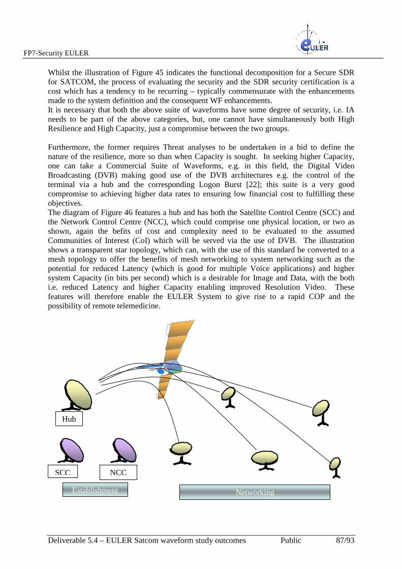
FP7-Security EULER
Deliverable 5.4 – EULER Satcom waveform study outcomes Public 87/93
Whilst the illustration of Figure 45 indicates the functional decomposition for a Secure SDR for SATCOM, the process of evaluating the security and the SDR security certification is a cost which has a tendency to be recurring – typically commensurate with the enhancements made to the system definition and the consequent WF enhancements. It is necessary that both the above suite of waveforms have some degree of security, i.e. IA needs to be part of the above categories, but, one cannot have simultaneously both High Resilience and High Capacity, just a compromise between the two groups. Furthermore, the former requires Threat analyses to be undertaken in a bid to define the nature of the resilience, more so than when Capacity is sought. In seeking higher Capacity, one can take a Commercial Suite of Waveforms, e.g. in this field, the Digital Video Broadcasting (DVB) making good use of the DVB architectures e.g. the control of the terminal via a hub and the corresponding Logon Burst [22]; this suite is a very good compromise to achieving higher data rates to ensuring low financial cost to fulfilling these objectives. The diagram of Figure 46 features a hub and has both the Satellite Control Centre (SCC) and the Network Control Centre (NCC), which could comprise one physical location, or two as shown, again the befits of cost and complexity need to be evaluated to the assumed Communities of Interest (CoI) which will be served via the use of DVB. The illustration shows a transparent star topology, which can, with the use of this standard be converted to a mesh topology to offer the benefits of mesh networking to system networking such as the potential for reduced Latency (which is good for multiple Voice applications) and higher system Capacity (in bits per second) which is a desirable for Image and Data, with the both i.e. reduced Latency and higher Capacity enabling improved Resolution Video. These features will therefore enable the EULER System to give rise to a rapid COP and the possibility of remote telemedicine.
SCC
NCC
Hub
Establishment Networking

FP7-Security EULER
Deliverable 5.4 – EULER Satcom waveform study outcomes Public 88/93
Figure 46: Example DVB Networking Image.
Therefore, a need exists to mitigate interference, as experienced in earthquake scenarios driving a need to ensure a highly resilient waveform and there is simultaneously a need for a higher capacity waveform. In both circumstances, there is a need to ensure that the IA needs of the waveform meet those supported by the P&GS personnel. SDR (e.g. the Astrium Keystone Proteus) delivers a good solution as it can supply both categories of waveforms (i.e. high resilience or high capacity), particularly for the SATCOM element and these can then be applied with the relevant IA for integration into P&GS waveforms. This enables both End-to-End (E2E) communications and the necessary COP to be formed, particularly for a broad international relief effort. The availability of higher data rates facilitates more sophisticated applications to be undertaken, e.g. video, data and positioning, compared to the necessary usage for voice services. As the situation is understood better following a natural disaster, the PPDR community can network better enabling better coordination of relief efforts and correspondingly improvements in Safety of Life (SoL) as is meant by a EULER SATCOM System.
9.4 EULER SATCOM Solution 1. IA needs to meet those expected by PPDR users e.g. TETRA, Tetrapol, Analogue FM 2. Wide range of Services needs to be provisioned e.g. Voice (with the possibility for
multiple Voice for conferencing in realtime), Video, Data and Position Fixing to enable COP to be formed
3. Degree of adaptability to varying channels needs to incorporated into system (e.g. due to interference at start of recovery process, which can be caused by a natural disaster) – such features are inherent in the Astrium Keystone Proteus which has been designed with recognition of a need to support multiple WFs to cater for both resilience and data capacity.
4. High data rates expected from the EULER SATCOM as it aggregates a number of EULER networks to facilitate the COP.
5. The ability to maintain an optimum throughput in a networked manner (e.g. DVB-S2 ACM or with DVB-RCS or RCS-NG) should environmental conditions start to impact on the satellite link and a high level of quality of service (QoS) to ensure that essential connections are maintained even under the worst conditions.
9.5 Summary A EULER SATCOM solution has been provided in this Section. In order to meet the needs of such a solution, it has been necessary to consider the needs of P&GS, i.e. operationally in a natural disaster the needs of communications are paramount. Furthermore, there is a requirement of rapid response to an international crisis: interference may be caused as a consequence of natural disaster e.g. in an earth quake there is a chance that the result is one or many rogue transmitter(s), and simultaneously, a devastation of the conventional terrestrial infrastructure. The only way, in such a situation to obtain a rapid recovery is through the use of SATCOM.

FP7-Security EULER
Deliverable 5.4 – EULER Satcom waveform study outcomes Public 89/93
In view of a need to generate as rapidly as possible a networked solution, one needs to take the various P&GS systems, which may be for example: TETRA, Tetrapol or analogue FM, for which an SDR solution is advocated and to form an interoperability via SATCOM to enable a COP. The Astrium Keystone Proteus System offers SATCOM with different waveforms which are
catered for, in a interference free or with some interference link and with some degree of QoS
– therefore effects of rouge transmitters can thus be managed.
Therefore a need exists to ensure that at least some of the modes of the various P&GS
systems are supported, at least in tunnel mode, i.e. where the SATCOM is delivering a
solution as would be expected in a terrestrial system, with the need to form either high
resilience or capacity as the situation dictates. This is where the EULER system offers a great
advantage: it can readily integrate with P&GS and can offer a varied performance, enabling a
rapid formation of the COP in differing channel conditions.
FP7-Security EULER
Deliverable 5.4 – EULER Satcom waveform study outcomes Public 90/93
10 Conclusions This report, i.e. D5.4, has considered the SATCOM elements of EULER. To this end,
consideration has been given to a number of scenarios, where SATCOM is central:
connecting two or more IANs and connection of IAN to JANs. The principal WFs for
SATCOM have been considered: i.e. both the EWF in SATCOM mode and the traditional
favourite of OFDMA have been simulated. This discussion has given rise to the EWSF,
whereby the main attributes of SATCOM differing from a non-SATCOM case have been
considered: i.e. the impacts of both the power and latency of maintaining a link were
simulated for a number of WFs.
It is clear that, when considering a EULER scenario the effects of security are essential, since
the solution is to bridge to P&GS communication, are as important as those of the
conventional SATCOM WF. This has been considered, and the IA need of Availability is the
primary focal point for EULER, which is where the SATCOM solution has a lot of merit. A
number of simulations have been performed to highlight these benefits.
Future satellite communications cannot prescind from the evolution of terrestrial broadcast
and broadband communication systems. In this perspective, development of new satellite
systems tends to align with that of terrestrial communications, leading to a full integration
between the two networks which allows to offer high data rates and high quality of service
anytime, anywhere. In this framework, we highlighted some of the fundamental trends that,
drive future research activities in the satellite communication areas.
In particular, the diffusion of OFDM-based air interfaces along with the introduction of
cooperative communications and MIMO techniques to overcome some of the typical satellite
impairments call for wideband and MIMO channel modeling, new coding and
synchronization schemes which include also new paradigms like distributed coding, virtual
MIMO, and interference cancelation techniques.
The SATCOM component will invariably be, as discussed in this report, a key element of the

FP7-Security EULER
Deliverable 5.4 – EULER Satcom waveform study outcomes Public 91/93
EULER solution. The dependence to SATCOM will be dictated by the nature of the disaster
event: the impact upon life and terrestrial communication will be greatest for larger disasters
and in such scenarios only the use of SATCOM can help to coordination P&GS thereby
alleviating the rescue efforts.
There is a need for both a diversity of applications (e.g. multiple voice, various video
channels) and an accurate identification of CoIs and their position where SATCOM offers a
unique advantage. As discussed in this report, there is a need to develop SDR within EULER
bearing new WF technologies (e.g. MIMO and new coding techniques) to give additional
capacity and resilience to the SATCOM solution.

FP7-Security EULER
Deliverable 5.4 – EULER Satcom waveform study outcomes Public 92/93
11 References [1] Project MESA, Technical Specification Group - System; “System Overview”, ETSI TR
170 012 V3.1.1 (2006-01); available at http://www.etsi.org.
(http://www.etsi.org/deliver/etsi_tr/170000_170099/170012/03.01.01_60/tr_170012v030101p.pdf)
[2] WiMAX fundamentals, Ed. Prentice Hall, feb. 2007.
[3] V. Selgnole et al., “General Design”, EULER Deliverable 3.2, vers. 1.0, Dec. 2010.
[4] “EULER Waveform Architecture”, EULER Deliverable 5.2, vers. 1.0, Dec. 2009.
[5] S. Cioni, G.E. Corazza, M. Neri, A. Vanelli-Coralli, “On the Use of OFDM Radio Interface for Satellite Digital Multimedia Broadcasting Systems”, International Journal of Satellite Communications and Networking, John Wiley & Sons, vol. 24, no. 2, pp. 153-167, March/April 2006.
[6] S. Cioni, G.E. Corazza, M. Neri, A. Vanelli-Coralli, “OFDM vs. HSDPA Comparison for Satellite Digital Multimedia Broadcasting Systems”, IEEE Globecom Conference 2005, St. Louis (Missouri), vol. 5, pp. 2922-2926, 28 November – 2 December, 2005.
[7] A. Baddeley, “Going Forward with JTRS,” Military Information Technology”, Vol. 9, No. 7, September 21, 2005. [8] British Association of Public Safety Communication Officers (BAPCO) website:
http://www.bapco.org.uk [9] BAPCO Journal, Oct 2007, PPDR communications – opportunity with S-band
Spectrum http://www.bapcojournal.com/news/fullstory.php/aid/891/ppdr_communications_-_opportunity_with_S-band_spectrum.html [Last Accessed: 27th July 2011].
[10] TerraStar coverage plan: http://www.terrestar.com/technology-solutions/technology-overview/
[11] Tetra Communications to Distribute Thuraya Broadband and Voice Solutions in Europe.
http://www.thuraya.com/about/profile/media-releases/tetra-communications-to%20distribute-thuraya-broadband-and-voice-solutions-in-europe
[12] Europetetra communications Thuraya broadband and voice solutions, Website: https://connect.thuraya.com/uniquesigdb3d63a2a12ea46c889458593a87e140/uniquesig0/InternalSite/InstallAndDetect.asp?resource_id=BCE44E7BA7944FD88B95D64CA9A2EFC7&login_type=8&site_name=connect&secure=1&orig_url=https%3a%2f%2fconnect.thuraya.com/uniquesigdb3d63a2a12ea46c889458593a87e140/uniquesig0%2fSecureconnectPortalHomePage%2f
[13] Iridium continues to supply critical communication requirements Website: http://www.bapcojournal.com/news/fullstory.php/aid/773/Iridium_continues_to_supply_critical_communication_requirements.html
[14] National Institute of Security and Technology (NIST) website:

FP7-Security EULER
Deliverable 5.4 – EULER Satcom waveform study outcomes Public 93/93
http://www.nist.gov [15] Sturman, T.A., Leschhorn, R. and Godor, G., D4.7.1 (R) SDR security threats,
analysis and mitigation techniques, March 2010. [16] National Police Improvement Agency (NPIA) website:
http://www.npia.police.uk [17] Sturman, T.A., Leschhorn, R., Godor G, Bott, R. and Fazekas, P., D4.7.2(R) SDR
Security Software, March 2011. [18] Pereria, J., Risk, Disaster and Emergency Management, EC Europa, SMi London,
June 2007. [19] Haykin, S. Communication Systems, 1988, Wiley. [20] Turkish Earthquake of 17th August 1999:
http://news.bbc.co.uk/onthisday/hi/dates/stories/august/17/newsid_2534000/2534245.atm
[21] Public Protection and Disaster Relief (PPDR) website: http://www.ero.dk
[22] Digital Video Broadcasting website: http://www.dvb.org