evaluation of motor vehicle fire initiation-and propagation
TRANSCRIPT

Evaluation of Motor Vehicle Fire Initiation-and Propagation, Vehicle Crash and Fire PropagationTest Program
Jack L. Jensen and Jeffrey SantrockGeneral Motors CorporationUSA98-s4-O-04
Jensen, page 1
Evaluation of Motor Vehicle Fire Initiation and Propagation, Vehicle Crash and Fire Propagation Test Program
Jack L. Jensen and Jeffrey SantrockGeneral Motors CorporationUSA98-S4-O-04
ABSTRACT
As part of the vehicle safety research outlined in theMarch 7, 1995 Settlement Agreement between GeneralMotors and the U.S. Department of Transportation,General Motors is conducting a series of vehicle crashand fue propagation tests. The vehicles used for thesetests include a passenger van, a rear wheel drivepassenger car, a front wheel drive passenger car and asport utility vehicle. Crash tests will be conducted tocharacterize potential ignition sources resulting fromcollision events. Standard ignition protocols will bedeveloped to simulate gasoline spill fires, electrical fues,and hot-manifold ignition of non-gasoline combustiblefluids. Fire propagation tests will be conducted tocharacterize fire propagation in crashed vehicles. Thecrash tested vehicles will be burned using the ignitionprotocols.
INTRODUCTION
On March 7, 1995, General Motors and the USDepartment of Transportation entered into an agreement(hereafter referred to as the Agreement) to settle a disputeregarding the safety of 1970-199 1 full-sized GM pickuptrucks equipped with fuel tanks mounted outboard of theframe rails. Part of this Agreement involves theestablishment of a 5 year, $10 million motor vehicle firesafety research program. The overall objectives of thisresearch program are to better understand how vehiclefires start and spread and to determine what can be doneto prevent, contain and extinguish such fires. To this end,GM and the National Highway Traffic SafetyAdministration (NHTSA) have jointly developed 14separate vehicle fire safety research projects. One ofthese projects, entitled “B.3 Fire Initiation andPropagation Tests”, is the subject of this technical report.
This report does not present results of any tests; these willbe documented in subsequent technical reports. Thefollowing statement describing Project B.3 was developedby GM and the National Highway Traffic SafetyAdministration:
“Vehicle crash tests, including for example frontal
and rear impacts, will be conducted. The crash testresults, particularly the fluid plumes that result fromcomponent failures during the collision events, willbe analyzed for fire initiation potential. These datawill be used to develop a standard initiation protocol.Crash tested vehicles will be burned, using thisstandard initiation protocol; and fire propagationcharacteristics, such as component temperatures,flame spread and combustion off-gases will bestudied, particularly in their effects in the passengercompartment.”
The project statement of work delineated three majorobjectives:
1.
2.
3.
Design and conduct vehicle crash tests toidentify fne initiation potential. Specificobjectives include:
l Determine potential heat sources such aselectrical shorts or hot surfaces during orafter the impact;
l Identify potential fuel sources including:gasoline leaks, other fluid leaks, presence ofhydrocarbon vapors resulting from fluidleaks, and solid fuel sources;
l Measure standard vehicle crashworthinessand occupant injury parameters.
As necessary, the crash test protocol developedfor this work will utilize specializedinstrumentation and test conditions not normallyused for vehicle certification or engineeringdevelopment.
Develop standard initiation protocols for thevehicle fire propagation tests. The objective ofthis task is to develop controlled, reproducible,and realistic procedures for igniting fnes for usein the vehicle fire tests. Ignition protocols willbe developed to simulate both enginecompartment fires and gasoline-pool fires.
Design and conduct vehicle fue propagationtests using the vehicles crash-tested in Task 1and the initiation protocols developed in Task 2.
Jensen, page 2

The objectives of the fire propagation testsinclude:
0 Determine the major paths and time-linesfor fire propagation, especially entry of fireinto the passenger compartment;
l Identify what components burn and measurethe thermal environments around thesecomponents during the fire;
l Measure air temperature, heat fluxes, andtoxic gas concentrations in the passengercompartment.
Two research laboratories with expertise in fire scienceare participating in this research program. The Buildingand Fire Research Laboratory of the National Institute ofStandards and Technology (NIST) is participatingthrough a cooperative research and developmentagreement (CRADA). Factory Mutual ResearchCorporation (FMRC) is involved in this research programthrough a research contract. Technical personnel fromGM and from the NI-ITSA selected the vehicles anddeveloped the crash test conditions to be used in this
program. Technical personnel from GM, NHTSA, NIST,and FMRC worked jointly to develop the protocols forfire initiation and for the fire propagation tests.
TEST VEHICLES
In order to represent the current United States vehiclefleet, several different vehicle types will be used for thesecrash tests. The purpose of the crash testing is not tocompare the performance of different vehicle models orvehicle types but rather to increase the understanding ofpost-collision fnes and how they start. As it will not befeasible to test all vehicle types currently available in themarket, the following four vehicle types were selected: 1)passenger van, 2) rear wheel drive mid-sized passengercar, 3) sport utility vehicle, and 4) front wheel drive mid-sized passenger car. Both a front- and a rear-wheel drivepassenger car will be tested because these vehicle typeshave significantly different power-train configurations.As shown in Table 1, the market segments represented bymidsize cars, vans, and sport utility vehicles,cumulatively account for greater than 50% of 1995United States passenger vehicle sales [ 11.
Table 1.Year-To-Date Sales of Passenger Cars and Light Trucks
in the United States for 1995 By Market Segment [l)(As Of October 15,1995)
DESIGN AND CONDUCT VEHICLE CRASHTESTS
Research Objectives
The objective of these crash tests is to develop a betterunderstanding of events that occur during a vehiclecollision which could result in a post-collision fire. Firerequires three components: a source of heat, a source offuel, and oxygen. Here, fuel refers to any flammable orcombustible material that can ignite when exposed toheat. Combustion is a self-sustaining gas-phase chemical
reaction in which the heat released by oxidation of thefuel is sufficient to maintain the oxidation process.Ignition of the fuel can occur by one of two mechanisms[2,3]. Piloted ignition occurs when a flame or sparkignites a fuel/air mixture, where the concentration of thefuel in air is within the lower- and upper-limits offlammability. Ignition can occur in the absence of a pilotsource if the temperature of the igniting object is greaterthan the autoignition temperature of one of its constituentmaterials.Potential fuels for a post-collision fire could be any of theflammable or combustible liquids, or combustible solids
Jensen, page 3

in the vehicle. Most automotive fluids are flammable orcombustible, or contain combustible constituents.Gasoline, motor oil, and power steering fluid are mixturesof hydrocarbons. Brake fluids conforming to DOT3 orDOT4 specifications [4] are composed of end-cappedpoly(glyco1 ethers). Although engine coolant and washerfluid are water-based, both fluids contain combustiblecomponents: ethylene or propylene glycol and methanol,respectively. Damage caused by the vehicle crush mayproduce leaks in some of the fluid systems, releasingthese fuels into or around the vehicle. The plastics andelastomers used in vehicles also are combustible. Theamount of thermal energy required to increase thetemperature of a combustible solid to above its flash-pointor fire-point is generally greater than that required for anyof the automotive fluids. One exception can be foamedsolid materials which, because of their lower density, areoften more easily ignited than liquids.
A number of ignition sources could be present during acrash, some of which are not present in an undeformedvehicle. Hot surfaces such as those of the exhaust system,which includes the exhaust manifold, exhaust pipes, andcatalytic converter, can act as an ignition source bytransferring thermal energy (heat) to a contactingcombustible material raising its temperature above theautoignition temperature for that material. Short circuitsin the electrical system caused by the vehicle crush canignite combustible materials by the same mechanism.Electrical arcing, metal-to-metal and metal-to-ground(road surface) friction-sparks can be piloted ignitionsources for a flammable vapor only if the concentration ofthe vapor is within its limits of flammability when andwhere the arc or spark occurs.
It is the goal of these tests to characterize both fuelsources and ignition sources in the vehicle crash testsdescribed below.
Crash Tests
To better represent the wide variety of crash conditionswhich may occur in the field, the four vehicle types willbe tested in different crash conditions. The criteria usedto develop these crash tests include the following:
l The crash tests are intended to be severe and donot represent current Federal Motor VehicleSafety Standards. Crashes of low severity whichdo not result in substantial damage to the vehiclestructure, the electrical system, or the fluidsystems would provide little information abouthow post-collision fires start.
l The intent of the crash test matrix is not tocompare the performance of vehicles or vehicletypes.
l The test matrix will include both frontal and rearimpacts per the terms of the Agreement.
l The crash tests should represent conditionswhich are field relevant,
An analysis of FARS (Fatal Accident Reporting System)data from 1979 through 1992 by the NHTSA [5] wasreviewed to identify those conditions which are fieldrelevant. This analysis suggested that frontal and rearimpacts should be included in this testing.
Frontal impacts will be included because there were morefrontal impacts than rear impacts, side impacts, orrollovers which resulted in a fne and a fatality. This wassimply because frontal impacts in general were morecommon than rear or side impacts. See Table 2, whichcombines the reported incidents for cars, trucks and vansfrom the NHTSA analysis.
Table 2.A 1994 NHTSA analysis of 1979 - 1992 FARS data [S]
Car, Trucks, and Vans
Jensen, page 4

Also included in Table 2 are those incidents in which firewas judged to be the most harmful event (MHEF). Notonly did frontal impacts result in the greatest number offrees, they also resulted in the greatest number of MHEF.As described in reference [5] the classification of fire asthe most harmful event is based on the personal judgmentof the FARS data analyst in each state. The fact that afire was identified as the most harmful event does notnecessarily mean that there was a fatality in the particularvehicle due to fire. Conversely, the fact that fire was notclassified as most harmful event does not preclude a firefatality for a particular crash analysis.
Even though there were fewer incidents of rear impactfatalities with a fire than frontal impact fatalities with afire, the probability of a fire given a rear impact wasabout twice that for frontal impacts. Moreover, theprobability of fire being the most harmful event given arear impact was approximately three times greater than
for frontal impacts. This supported including at least onerear impact in the test matrix.
The NHTSA study [5] of incidents resulting in a fire andfatality suggested that the most common object struck isanother vehicle, as indicated in Table 3. However, thelikelihood of fire was greatest for impacts to narrowobjects (e.g., trees).
The three crash conditions used for this project, includetwo frontal impacts and one rear impact. These crashconditions simulate either a vehicle-to-vehicle or vehicle-to-narrow object impact. The speeds were selected usingengineering judgment rather than an analysis of field data,and are intended to produce significant damage to thevehicle’s structure, electrical or fluid systems. All vehiclecrash tests will be conducted at the General MotorsProving Ground in Milford, Michigan.
Table 3.A 1994 NHTSA analysis of 1979 - 1992 FARS data [S]
Car, Trucks, and Vans
Deformable Rear Moviw Barrier at 85 km/h. Amoving barrier similar to the FMVSS 214 [6] vehicleimpactor will be used to impact the stationary test vehiclein the rear with a 70% overlap of the filler neck side ofthe vehicle. The direction of impact will be parallel withthe center line of the vehicle. And, unlike FMVSS 214,the wheels of the barrier will be aligned with thelongitudinal axis of the barrier. The barrier will have animpact velocity of 85 km/h (53 mph). The offset will beset so that 70% of the vehicle will be engaged (measuringthe width of the vehicle as the widest part of the bodyvertically in line with the center of the rear wheels.) Thestandard FMVSS 214 deformable face will be used andwill be positioned at its standard height (bumpercenterline 17” above grade.) The mass of the movingbarrier will be 1367 kg (3015 lb).
7OoIc OverlaDeformableMovingBarrier
85 km/h(53 mph)
Jensen, page 5
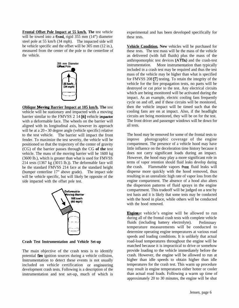
Frontal Offset Pole Impact at 55 km/h. The test vehiclewill be towed into a fmed, rigid 355 mm (14”) diametersteel pole at 55 km/h (34 mph). The impacted side willbe vehicle specific and the offset will be 305 mm (12 in.),measured from the center of the pole to the centerline ofthe vehicle.
355 mm DiameterOhat Pole
Oblique Moving Barrier Impact at 105 km/h. The testvehicle will be stationary and impacted with a movingbarrier similar to the FMVSS 2 14 [6] vehicle impactorwith a deformable face. The wheels on the barrier willaligned with its longitudinal axis, however its approachwill be at a 20 - 30 degree angle (vehicle specific) relativeto the test vehicle. The barrier will impact the frontfender. To maximize the test severity, the vehicle will bepositioned so that the trajectory of the center of gravity(CG) of the barrier passes through the CG of the testvehicle. The mass of the moving barrier will be 1600 kg(3600 lb.), which is greater than what is used for FMVSS214 tests (1367 kg (3015 lb.)). The deformable face willbe the standard FMVSS 214 face at the standard height(bumper centerline 17” above grade). The impact sidewill be vehicle specific, but will likely be opposite of theside impacted with the offset pole test.
Crash Test Instrumentation and Vehicle Set-up
The main objective of the crash tests is to identifypotential fne ignition sources during a vehicle collision,Instrumentation to detect these events is not usuallyincluded on vehicle certification or engineeringdevelopment crash tests. Following is a description of theinstrumentation and test set-up, much of which is
experimental and has been developed specifically forthese tests.
Vehicle Condition. New vehicles will be purchased forthese tests. The test mass will be the mass of the vehicleas delivered (with full fluids) plus the mass of theanthropomorphic test devices (ATDs) and the crash-testinstrumentation. More instrumentation than typicallyincluded in a crash test may be required and thus the testmass of the vehicle may be higher than what is specifiedfor FMVSS 208 [7] testing. To retain the integrity of thevehicle for the fire propagation tests, no parts will bedestroyed or cut prior to the test. Any electrical circuitswhich are being monitored will be activated during theimpact. As an example, electric cooling fans frequentlycycle on and off, and if these circuits will be monitored,then the vehicle impact will be timed such that thecooling fans are on at impact. Also, if the headlightcircuits are being monitored, they will be on for the test.The front driver and passenger windows will be down forall tests.
The hood may be removed for some of the frontal tests toimprove photographic coverage of the enginecompartment. The presence of a vehicle hood may havelittle influence on the deceleration time history because itdoes not carry significant loads during an impact.However, the hood may play a more significant role interms of vapor retention should fluid leaks develop duringthe crash. Flammable vapors from fluid leaks willdisperse more quickly with the hood removed, thusresulting in an unrealistic high rate of vapor loss from theengine compartment. The absence of a hood also altersthe dispersion patterns of fluid sprays in the enginecompartment. This tradeoff will be judged on a test bytest basis and it is likely that some tests may be conductedwith the hood in place, while others will be conductedwith the hood removed.
The test vehicle’s engine will be allowed to runEngine.during all of the frontal crash tests with complete vehiclefluids (including battery electrolyte). Preliminarytemperature measurements will be conducted todetermine operating engine temperatures at various roadspeeds and loading conditions. It is unlikely that actualroad-load temperatures throughout the engine will bematched because it is impractical to drive or somehowprovide loading to the vehicle immediately before thecrash. However, the engine will be allowed to run athigher than idle speeds to obtain higher than idletemperatures for the crash test. This warm up proceduremay result in engine temperatures either hotter or coolerthan actual road loads. Following a warm up time ofapproximately 20 to 30 minutes, the engine will be shut
Jensen, page 6

down for instrumentation calibration and set-up(approximately 5 minutes). The engine will be restartedand engine speed will again be increased to above idlespeed. Gasoline will be supplied to the engine from anauxiliary fuel tank mounted inside the passengercompartment and connected to the gasoline supply lineaway from any anticipated vehicle crush. A productionfuel pump system will be installed in this auxiliary tankand electrically connnected in place of the existing pump.The production gas tank will be filled to 95% of its usablecapacity with Stoddard Solvent.
For the rear impact tests, the fuel tank will be filled to95% of its usable capacity with Stoddard Solvent. Theengine will not be running during the crash test, nor will ithave been run prior to the test to minimize the probabilityof igniting spilled Stoddard Solvent if a fuel system-rupture should occur. However, the ignition will be onand the fuel lines charged. A plastic bag will be sealedaround the filler cap to retain and detect the presence ofStoddard Solvent that has escaped from the cap during theimpact. Normal collection procedures used for FMVSS30 1 [S] testing will be used to quantify fuel system leaksafter the impact.
Electrical Current and VoltaPe. Some, but not all, ofthe vehicle’s electrical systems will be measured duringthe crash test to help identify potential electrical shortswhich may result in ignition sources. Thesemeasurements may include both voltages and currents.The currents will be monitored using clamp-on non-intrusive current transducers, while voltages will bemeasured directly. It will be impractical to measure thecondition of every engine compartment circuit, and soprudent engineering judgment will be used to helpidentify those circuits which are most likely to bedamaged by the impact and possibly result in an ignitionsource. Electrical circuits to be monitored during thefrontal tests may include the starter wire, the alternatorwire, main battery feeds, the electric cooling fans, theheadlights and other circuits specific to the vehicle.Circuits to be monitored for the rear impacts may includethe rear taillights, the center high mounted stop light, therear window defroster and other vehicle specific circuits.
Fluid Pressure. Pressure transducers (Model 85 10B and85 1OC Pressure Transducers, Endevco, San JaunCapistrano, CA) will be installed to measure the dynamicpressures of key vehicle fluids during the frontal impacts.This will help identify the times at which a fluid leaks sothey may be correlated to structural damage during thecrash. For the frontal tests, fluid pressures will bemeasured in the gasoline supply and return lines, the frontbrake lines, the engine coolant system, the power steering
system, engine crankcase, and transmission. For the rearcrash tests, fluid pressures will be measured only in thegasoline supply and return lines.
Fuel Pump. For the frontal crash tests, the fuel pumplocating in the auxiliary fuel tank will be operating (aswell as the engine.) The electrical power to the fuel pumpwill be measured to determine when the fuel pump stops.In addition, the rotation of the engine will be measuredeither by monitoring the on-board engine-speed sendingunit and/or by mounting a magnetic speed sensor (ModelMPI A High Sensitivity Magnetic Pickup, PhilipsTechnologies, Airpax Instruments, Chesire, CT) adjacentto the flywheel. Some vehicle fuel pumps are designed toshut down when the engine rotation stops, which typicallyoccurs with severe frontal impacts. These twomeasurements allow the correlation of engine speed tofuel pump status.
Flammable Vapors. Two types of chemical analyseswill be performed during the crash test to determine thecontribution of fluid leaks to the development of apotentially flammable fuel/air mixture. Theconcentrations of flammable vapors will be measuredwith tin oxide semiconductor gas sensors (TGS 813,FIGARO USA, Inc, Wilmette, IL). These sensors arecrashworthy, have a fast response, require minimalelectronic circuitry, but require careful calibration foraccurate measurements.
In addition to the measurements of flammable vaporconcentration, samples from each sensor-location will becollected on sorbent cartridges for analysis. The gasesretained on the sorbent material in these cartridges will beidentified by thermal desorption/gas chromatography orbY thermal desorption/gas chromatography/massspectrometry. Elucidation of the chemical composition ofthe gases at each location will help to identify the sourceof the flammable vapor.
Instrumentation to perform these measurements will beincluded in all the frontal crash tests. For the frontalcrash tests, gas sensors and sampling tubes will be locatednear potential ignition sources (e.g., hot surfaces andlikely points of electrical arcing). Since the fuel tank willcontain Stoddard Solvent, which has a significantly lowervapor pressure than gasoline, flammable vapormeasurements will not be performed during the rearimpact tests.
Vehicle Brakes. The dynamic brake fluid pressure willbe monitored in the frontal tests in order to identify thetimes of potential brake fluid leaks.
Jensen, page 7
For the offset pole tests, the brake lines to the frontwheels may be isolated from the brake calipers allowingthe brake lines to be charged but still allowing the wheelto turn during the vehicle tow. This will be done so asteady state brake pressure can be measured and any dropin brake pressure during the impact will be easilyidentifiable. For typical crash tests, an auxiliary brakemachine is sometimes used to apply the brakes remotelyat or shortly after impact. During the initial application ofthe brakes, however, there is a time delay in the rise ofbrake pressure and a steady state pressure may not berealized during the time of any leaks. It is desirable tohave the brake lines pre-charged during the vehicle tow toidentify more clearly a drop in brake pressure. Also forthe pole test, an auxiliary brake machine will beconnected to the rear brakes and used only to abort thetest, if necessary, during tow. For the oblique movingbarrier test, the rear brakes will be disconnected from thebrake lines and charged by an auxiliary brake machine.The front brakes will be pressurized by loading the brakepedal and mechanically locking it down.
For the rear impacts, the front brakes will be activatedwith the auxiliary brake machine within 200 msecfollowing the impact to help control the post-impactvehicle motion. The brake line pressure will not bemonitored during these tests.
Crashworthiness of Experimental Fire Detection andSuppression Devices. Project “B.4 Evaluation ofPotential Fire Intervention Materials and Technologies”involves evaluation of fire detection and suppressionsystems for automotive applications. The crash testsdescribed here provide an excellent opportunity toevaluate the crashworthiness of several proposeddetection or suppression technologies. Therefore, someexperimental fne detection devices will be included onsome of the crash tests. Examples of technologies to beevaluated include, thermal wire fire detectors, pneumaticfne detectors, and optical fne detection systems. Thepurpose of including some of these on the crash tests is toidentify whether or not these devices would survive thecrash and remain functional after the impact. This will bestrongly dependent on the placement of the device in theengine compartment, and therefore, various locations willbe evaluated.
Anthropomorphic Test Devices. Instrumented 5@percentile male Hybrid III crash dummies will be placedin both outboard front seating positions and will berestrained by the vehicle’s production seat belt and airbag restraint systems. Seat and dummy positioning willbe done per FMVSS 208 [7] procedures. InstrumentedATDs will be included to represent the dynamic inertial
loading of the occupant on the vehicle and also to assessthe survivability of these selected crash conditions froman occupant trauma standpoint. For the frontal tests, fulldummy instrumentation will be recorded which includes:the measurement of head accelerations, neck loads, chestaccelerations, chest compression, pelvic acceleration,femur loads, and several lower leg load measurements.For the rear impacts only the head, neck and chestmeasurements will be recorded. Most of the injuryassessment reference values for the Hybrid III ATDaccepted by the automobile industry were developed forfrontal loading, therefore, injury measurements recordedduring the rear impacts will be interpreted accordinglyand generally with less confidence in predicting injuryrisk than for frontal impacts.
Crash Test Instrumentation. These tests will usestandard vehicle crash-testing instrumentation in additionto the specialized instrumentation developed to identifyignition sources. These standard measurements of thevehicle include accelerations at various locations on thevehicle, linear displacements, and contacts. All vehicleand ATD channels will be recorded remotely (off-board)using drag-cables which connect the transducers to thesignal conditioning and data acquisition equipment.
All transducer signals will be recorded using a digital dataacquisition system (DSP Technology, Fremont, CA) at10,000 samples per second with 12 bit resolution. Thesechannels will use remote shunt emulation forinstrumentation set-up and will be recorded for 28seconds. Signal conditioning, filtering, and recordingtechniques will comply to SAE 3211 [9].
Some channels, including the time-zero contact, the vapormeasurements, and electrical measurements will also berecorded using a remote, PC-based digital data acquisitionsystem for approximately 10 minutes after the impact.From the start of tow to the time of impact, the dataacquisition rate will be 1,000 samples per second. Thedata acquisition rate will be switched to 10 samples persecond after the impact.
Photo Coverape. Standard high speed movie coveragewill be used to record the crash tests. Typically 15 - 30high speed (500 or 1000 frames per second) cameras willbe used depending on the test configuration. Coverageunder the vehicle will be included for the rear and poleimpact tests. Numeric film analysis will be done tomeasure vehicle motion. As an example, the dynamicpole penetration during the pole impact test will bemeasured using film analysis. In addition to high speedfilm, real time documentary video cameras will be used to
Jensen, page 8
record the vehicle condition for at least 10 minutesfollowing the test.
Post-test Inspections. Following each crash test, the testvehicles will be partially disassembled to allow for athorough inspection and documentation of possibleignition sources or fire paths into the passengercompartment. Fluid leaks, electrical shorts and structuraldamage to the vehicles will be photographed anddocumented.
Post-test Static Rollover. Static rollovers, similar to anFMVSS 301 [8] rollover will be conducted only afterselected tests. A rollover will be completed for each ofthe rear impacts, but not for all of the frontal impacts.This will be decided on a test by test basis. Thedrawbacks to conducting a static rollover, especially forthose vehicles which will be burned, is that the roll maydistribute the engine compartment fluids into thepassenger compartment. (For example, the vehicle usedin the first frontal crash test of this program was rolledand the cracked windshield, the carpet, and the headlinerwere contaminated by a significant amount of leakingengine compartment fluids.) This contamination couldserve as an accelerant, significantly altering firepropagation during the vehicle fne tests. For this reason,most of the frontal test vehicles will not be rolled.
DEVELOPMENT OF STANDARD IGNITIONPROTOCOLS
Potential ignition events observed during the crash testswill be the basis for the Standard Initiation Protocols.Simply stated, a Standard Initiation Protocol is arepeatable method for starting a fire for a vehicle fire test.To be useful for the vehicle fne tests, a standard initiationprotocol should meet three requirements. First, it mustresult in an ignition. Second, the ignition must lead to apropagating fue; that is, a fire that does not self-extinguish before spreading from the site of ignition.Lastly, it must be a repeatable and controllable procedure.Thus, factors such as 1) the locations of potential fuel andenergy sources in the vehicle, 2) the type, amount, andflammability properties of the fuel, 3) the type, intensity,and duration of the energy source, and 4) theflammability properties of combustible materials in closeproximity to the site of ignition must be considered whenexamining the data from the crash tests and whendeveloping the standard initiation protocols. Some ofthese parameters may be studied in small-scale test beforedeveloping the initiation protocols for the full-scalevehicle fne tests. When appropriate, information aboutpost-collision vehicle fnes obtained from other sources
(e.g., field incident data, crash data bases) willconsidered when developing these initiation protocols.
be
Technical personnel from GM, NIITSA, NIST, andFMRC will work jointly to develop standard initiationprotocols for ignition of combustible materials in theengine compartment and for ignition of a gasoline poolunder the vehicle. These initiation protocols will bedescribed in detail in future reports.
Ignition in the Engine Compartment
Possible ignition scenarios for engine compartmentto be examined in small scale tests include:
l Ignition of combustible solids in the enginecompartment by heat generated from anelectrical short, which could include an internalshort in the battery;
l Ignition of a combustible liquid sprayed onto ahot surface; or
l Ignition of gasoline leaking from a ruptured fuelline by an electrical arc.
These scenarios will be examined fordevelopment into a standard initiation protocol.
fires
possible
Ignition of a Gasoline Spill
The initiation protocol for vehicles struck in the rear willfocus on ignition of gasoline leaking from a ruptured fuelsystem. There are two possible outcomes of the crash testwith regards to fuel system integrity:
l The fuel system ruptures and leaking fluid isdetected during the crash test or the vehicle roll,or
l The fuel system does not rupture and leakingfluid is not detected during the crash test or thevehicle roll.
When the crash test results in fluid leaking from aruptured fuel system, the initiation protocol will recreateas accurately as possible the location of the leak, the leak-rate, and the size and location of the liquid pool relative tothe stationary vehicle.
When the fuel system does not rupture and does not leakduring the crash test, the ignition protocol will simulate arupture of the fuel-system at the connection of the filler-neck to the fuel tank. Different procedures will be usedfor vehicles with steel and plastic fuel tanks. For vehiclesequipped with plastic fuel tanks, a 3 mm diameter holewill be drilled at the base of the filler neck and the fuel
Jensen, page 9

tank will be partially filled with gasoline. For vehiclesequipped with steel fuel tanks, gasoline will be pumpedfrom an external reservoir through a grounded stainlesssteel tube with the outlet affixed to the base of the fillerneck. For simplicity, the gasoline pool will be ignitedwith a pilot flame in these tests.
DESIGN AND CONDUCT VEHICLE FIREPROPAGATION TESTS
Objectives
Understanding fire propagation in vehicles with thestructure damaged in a crash is a fast step in developingeffective measures to reduce injuries and fatalitiesassociated with post-collision vehicle fires. Both theprobability of a post-collision vehicle fne and theprobability of sustaining an incapacitating trauma injuryor of being trapped in the vehicle after the crash increaseas the severity of the crash increases [5]. In cases where acollision results in both a fire and surviving occupantsbeing trapped in the vehicle, entry of the fire into thepassenger compartment is the greatest, immediate threatto the occupants. The crash-tested vehicles will beburned in controlled tests to study propagation of a post-collision fne.
The literature contains several reports documentinginvestigations of motor vehicle fires. These reportsgenerally fall into two categories: case studies of forensicinvestigations of motor vehicle fires [lo- 121, or technicalreports describing the results of vehicle fire experimentsusing uncrashed vehicles [ 13- 161. The forensicinvestigations [ lo- 121 were generally concerned withdetermining the cause and origin of a motor vehicle fireafter a crash or when arson is suspected. Forensicinvestigations focus on the ignition event and usually donot provide detailed information about how the firepropagated for two reasons. First, fire investigationsoccur after-the-fact; the investigators are not present toobserve the fire. Second, much of the evidence needed todetermine the fue paths was usually destroyed in the fries.
Most controlled vehicle fue tests have been concernedwith determining the effect of a burning vehicle onsurrounding structures [ 13- 151, which involves measuringheat-transfer to surrounding objects. One studyinvestigated propagation of an engine compartment firethrough the forward bulkhead, using a series of front-halfsections of uncrashed vehicles [ 171. Neither the results ofthe fne investigations nor the controlled studies citedabove can be generalized to propagation of post-collisionvehicle fires.
The vehicle fire tests described below will focus onunderstanding how fire propagates in crashed vehicles.Data recorded during these tests will be used to (1)determine the paths for the spread of flame from the siteof ignition to other locations in the vehicle, (2) measurethe rate of flame-spread along each of these paths, (3)determine what components and materials burn, and (4)assess occupant survivability during the fire.
Fire Paths. Two of the objectives of these tests are todetermine how the fire moves from the exterior of thevehicle into the passenger compartment, and to determinethe time-line for this process. Possible fire paths into thepassenger compartment include:
l polymer grommets used as seals in electrical,fluid, and mechanical feed-throughs in the sheetmetal bulkheads around the passengercompartment;
l openings in the sheet metal structure of thevehicle created by the crush;
l the windshield, which can be shattered in thecrash or by heat from the fire;
0 windows, which may be open, or shattered in thecrash or by heat fkom the fire;
l heat transfer through the sheet metal structures(e.g., the forward bulkhead and the floor pan) tocombustible materials in contact with thesestructures (e.g., the carpet pad).
A distinction is made here between the windshield andother windows in the vehicle. The windshield is alaminated structure consisting of a polymer sheetsandwiched by two outer-layers of tempered glass.Although the glass layers may shatter during the crash,the polymer sheet is less brittle and can hold the shatteredwindshield in place. In contrast, other windows in thevehicle typically consist of a single layer of temperedglass, and may not remain in place when shattered.
Temperatures and Thermal Environments. Anotherobjective of these tests is to identify what componentsbum. In addition to flammable or combustible fluids,vehicles contain a number of components composed oforganic polymers (plastics and elastomers). In general,all of these polymeric materials are combustible, and canbe a fuel source in a post-collision fire.
Thus, the flammability of the constituent materials of thevarious components in the vehicle will affect both whereand how fast the fire propagates. These fue tests willyield detailed information about what components bum,the sequence in which they ignite, the thermalenvironments around these components before and when
Jensen, page 10

they are burning, and the rate of growth and heat outputof the fire.
Threat to Occupants. Another goal of these tests is todetermine the threat to occupants posed by a post-collision fire. Fire can injure or kill by one or acombination of three basic mechanisms:
l Burns to the skin caused by hot gases andthermal radiation to the body or by flamedirectly contacting the skin;
l Burns to the lungs caused by inhalation of hotgases; or
l Acute toxicity caused by inhalation of toxiccombustion products.
Instrumentation will be included in the vehicles to assessthe threat from each of these mechanisms.
Fire Propagation Test Procedures
Eight fire propagation tests will be conducted at theFactory Mutual Test Center in West Glocester, RhodeIsland. Two crash-tested vehicles per model will beselected for the fue propagation tests. The selection ofthe vehicles for fire propagation tests will be done bytechnical personnel from GM and NHTSA with inputfrom technical personnel from the NIST and FMRC. TheNIST will be responsible for all aspects of obtaining adetailed video record of each fire propagation test andanalysis of these video records to determine the importantevents in the propagation of the fire from the site ofignition into the passenger compartment. FMRC will beresponsible for preparing the fluid containment pan,weight-modules, and simulated road surface before eachtest, and for operation of the Fire Products Collectorduring each test. GM will be responsible for all otheraspects of the preparation and conduct of the fne testsdescribed below.
One of the vehicles used in the frontal crash tests (offsetpole test or deformable oblique moving barrier) will beselected for the engine compartment fire test. If one of thefrontal crash tests results in a fne, then this vehicle will beselected for the fue test and the method of ignition willrecreate as accurately as possible the cause of the fueobserved in the crash test. If none of the frontal crashtests results in a fire for a given vehicle type, then themethod of ignition for the fire test will recreate possibleignition scenarios determined after examination of thedata from the crash test, disassembly and thoroughinspection of the vehicle selected for the fne test. Thevehicle used in the rear crash test will be used for thegasoline pool fire test.
Vehicle Condition. The condition of the vehicle for thefire test will approximate the condition of the vehicleafter the crash test. For fire tests involving vehicles inwhich the hood was removed for the crash test, the hoodwill be crushed dynamically to simulate the crush thatwould have occurred in during the crash test andremounted on the vehicle. For maximum retention of heatand combustion gases in the passenger compartment, allintact windows will be raised to their fully closed ormaximally closed positions. Windows broken during thecrash test will not be replaced for the fire tests.Components which separate from the vehicle during thecrash tests will be collected and placed in the samepositions relative to the vehicle. The entire vehicle,including the engine compartment will be at ambienttemperature at the start of the fire test. Automotive fluidswill be spilled in the engine compartment and under thevehicle before the fire test to simulate fluid leaks thatoccurred during the crash test.
Fire Test Facilitv. The vehicles will be centered under aFire Products Collector [ 18,191. The Fire ProductsCollector is a large-scale calorimeter which will be usedto obtain the release-rates of chemical, convective, andradiative heat, and of carbon dioxide, carbon monoxide,total hydrocarbons, and smoke during a fire test.
To prevent personal injury, fue damage to the testfacility, and environmental contamination, the vehiclewill be placed in a containment pan to prevent leakingautomotive fluids from spreading in the test facilityduring and after the fire tests.
The bottom of the fluid containment pan will be linedwith a simulated road surface consisting a layer ofconcrete construction board on top of a bed of sand. Thepurpose of the simulated road surface is to accuratelyrecreate the effect of a semi-porous medium on fluid poolfrees which may develop during these tests. The seamsbetween boards will be sealed with latex constructioncaulk and the grade of the surface measured from thecenter to the edges along the major and minor axes willbe no greater than 1% in all directions. This lastspecification is to minimize the effect of flaming fluidpools accumulating at low points in the surface.
Mass loss from the burning vehicle and any burningfluids retained by the containment pan will be measuredwith load cells. The fluid containment pan will be placedon top of an I-beam fiarne supported by weight-modules(KIS Series, BLH Electronics, Inc.) at each of its fourcomers. These weight-modules contain cylindrical,double cantilever strain gauge transducers that will not be
Jensen, page 11

affected by changescontainment Pan
in the mass distribution in the
Vehicle Instrumentation
Temperature. Thermocouples will be attached to metalbulkheads, and various components in the vehicles alonganticipated fire paths or near combustible components inthose paths. Temperature measurements obtained withthese thermocouples will be used to track the spread ofthe fire and to define the thermal environments in thevehicle during the fire. The locations for thermocoupleplacement will be determined after disassembly andthorough inspection of the crashed vehicles.
Type-N thermocouples (Nicrosil/Nisil) will be used forthese measurements. These thermocouples will haveungrounded junctions enclosed in an Jnconel 600 sheathand insulated with magnesium oxide (MedthermCorporation, Huntsville Alabama). The higherthermoelectric stability of Type-N thermocouplecompared to the standard base-metal thermocouples [20]will yield more reliable temperature measurements in theextreme environment of the fne tests.
Each thermocouple will be connected to the dataacquisition system with thermocouple duplex extensioncable with a Teflon@-jacketed stainless steel over-braid.To minimize electromagnetic interference and to preventground-loops, the electronics chassis ground, thethermocouple shields, and the vehicle chassis will beconnected to a common ground-bus at the dataacquisition system. The ground-bus will be connected toearth-ground by a large gage cable.
Air Temperature. Two aspirated thermocouple probeassemblies (Medtherm Corporation) will be used tomeasure vertical air-temperature gradients at the frontoccupant positions. Each assembly will contain six Type-N thermocouples with bead-type junctions. Thethermocouples will be housed in radiation shields with avertical spacing of 75 mm (3 in.). The probes will bemounted to the roof of the passenger compartment so thatthe upper-most shielded thermocouple is approximately12 mm (0.5 in.) below the lower surface of the head liner.Both probe assemblies will be connected to a vacuumpump to draw air into the radiation shields. The internaldiameters of the interconnecting sections of the vacuummanifold will be sized to approximately balance the gasflow rate into each radiation shield, yielding a linearvelocity of air flowing over the thermocouple junctions of10 to 15 m/s. These conditions were chosen to minimizeboth the response-time of the thermocouples and error in
the air temperature measurement due to radiative heat-transfer to the thermocouple bead [2 1 ].
Heat Flux. Dual heat-flux transducer/radiometerassemblies will be mounted to selected components andmetal bulkheads in the vehicle to measure convection andradiation to objects in the anticipated fire paths. Theseassemblies will contain two Schmidt-Boelter thermopilesin a water cooled copper body (Medtherm Corporation).The faces of the heat flux transducers will be coated withhigh-temperature optical black paint. The radiometerswill have sapphire windows (view-angle = 150”; opticaltransmittance range 0.4 to 4.2 pm). Both types oftransducers will be calibrated to 10 W/cm2 at a referencetemperature of 80°C.
Dual heat-flux transducer/radiometer assemblies also willbe located in the passenger compartment to measureconvection and radiation to the occupant positions. Theseassemblies will contain two Schmidt-Boelter thermopilesin a water cooled copper body (Medtherm Corporation).The faces of the heat flux transducers will be coated withhigh-temperature optical black paint. The radiometerswill have zinc selenide (ZnSe) windows (view-angle =150”, optical transmitance range of 0.7 to 17 pm). Bothtypes of transducer will be calibrated to 2 W/cm2 at areference temperature of 80°C.
Static Pressure. The static air pressures at severallocations in the vehicle will be measured using bi-directional low differential pressure gages (Model C-264,Setra Systems, Acton, MA). The pressure gauges will belocated outside of the fluid containment pan to protectthem from the fire, and will be connected to stainless steeltubes terminating in the vehicle. For measurement of thestatic pressures, one port of the pressure gauges will beleft open to the atmosphere so that these measurementswill have a common, unchanging reference. Formeasurement of pressure differences across structuralbulkheads, both ports of the pressure gauges will beconnected to the stainless steel tubes terminating onopposite sides of the bulkhead. Pressure data will berecorded by the data acquisition system as analog inputs.
B&directional Flow. Directional gas flow velocity willbe measured using a bi-directional flow probe connectedto one of the low differential pressure gages describedabove. The differential pressure is related to the flowvelocity by the relationship:
V=O.O7q/TL
Jensen, page 12
where Y is the linear flow rate (m/s), T is the absolutetemperature (K), and Ap is the pressure differencebetween the two openings in the probe (Pa). The probewill be placed near the top of an opening in the vehicle tomeasure the velocity of gas flow into or out-of the vehicleduring the fue test [22,23].
Data Acquisition Svstem. The data acquisition systemto be used in the fire tests consists of a PC (ACER Inc.,Taiwan R. 0. C.) and a 100 kHz I/O board with 16 analoginput channels (DaqBoard 200A, IOTech, Inc.,Cleveland, OH). Four multiplexed analog-inputexpansion cards (DBK-12, IOTech) will be used for amaximum of 64 variable gain analog input channels forthe heat flux transducers, radiometers, and pressuretransducers. Twelve multiplexed thermocoupleexpansion cards (DBK-19, IOTech) will be used for amaximum of 168 thermocouple input channels. Theexpansion cards will be housed in a shielded metalcabinet with panel-mounted connectors.
The data acquisition software (DASYLab, Daten SystemTech& GmbH, Msnchengladbach, Germany) will beconfigured to sample each channel at a rate of 10 samplesper second and store the data in IO-point block averages.Thus, data will be recorded at a rate of 1 sample persecond per channel. To facilitate the decision to end thetest, air temperature and heat fluxes at the occupantpositions will be displayed in real-time during each test.
Video Camera Coverage. Hi-8 color camcorders will bepositioned outside the vehicle to document each fire test.The cameras will be arranged around the vehicle to givepartially overlapping views of the fire, with emphasis onanticipated fue propagation paths into the passengercompartment. The location of each camera relative to thevehicle will be mapped on a 3-dimensional coordinatesystem to facilitate the determination of the location ofthe flame on the vehicle and the rate of flame spread.One or more inexpensive CCD cameras mounted in fire-resistant housings may be located inside the passengercompartment to give views of the anticipated firepropagation paths.
Infrared Thermoeraphv. Infrared imaging equipmentwill be used to obtain estimates of flame and surfacetemperatures during the fire tests. Thermal imagingradiometers will be positioned outside the vehicle to giveviews similar to those of some of the video cameras. Inaddition, one camera protected by a fire-resistant housingwill be mounted inside the vehicle to give a clear view ofone of the anticipated fire paths into the passengercompartment.
The infrared imaging equipment to be used for these testswill include thermal imaging radiometers with spectralwindows in the range of 3 to 5 micron (short-wave), 8 to12 microns (long-wave), and 3 to 12 micron (broad-band). Flame filters with a cut-off wavelength of 3.9microns may be used to eliminate radiation from theflame. An older, short-wave camera with a spectral rangeof 3 to 5 microns will be mounted inside the vehiclesduring the fire tests.
FTIR Spectrometrv. Combustion gases accumulating inthe passenger compartment during the fire test will bemeasured by Fourier transform infrared (FTIR)spectrometry. These gases include: ammonia (NH3),benzene (C,H,), carbon dioxide (CO,), carbon monoxide(CO), hydrogen chloride @ICI), hydrogen cyanide(HCN), methane (CH,), nitric oxide (NO), nitrogendioxide (N02), and styrene (C,H,). The spectrometer tobe used for these measurements (Model 11000, MIDACCorporation, Irvine, CA) will be equipped with a heated,stainless steel gas cell (path length = 10 m) with gold-surfaced mirrors and ZnSe windows, a liquid-nitrogen-cooled Mercury-Cadmium-Telluride detector, and aMichelson-Type interferometer with a PotassiumBromide beam splitter. The optical range of thisinstrument will be 5,555 to 645 cm-‘. The optical benchwill be hermetically sealed and desiccated, isolating theinternal optics and electronics from the harshenvironment in the fire test facility and eliminating theneed for continuous purge during the test.
During the fire tests, air from the passenger compartmentwill be drawn continuously into the gas cell through astainless steel tube inserted into the breathing zone of thefront occupants. Single-scan spectra with a resolution of0.5 cm-’ will be acquired every 10 seconds. Gasconcentrations will be determined using a Classical LeastSquares algorithm. To facilitate the decision to end thetest, the carbon monoxide concentration in the passengercompartment will be displayed in real-time during eachtest.
Gas ChromatoPraphvbMass Spectrometrv. Organicgases in the passenger compartment will be collected onsorbent cartridges packed with Graphitized Tenax@ andanalyzed by gas chromatography/mass spectrometry. Airfrom the passenger compartment will be sampled througha stainless steel tube inserted into the breathing zone ofthe front occupants. A series of five pairs of sequentialsamples will be acquired during the fire tests; one samplewill be collected at a flow rate of 250 cm3/min (correctedto standard temperature and pressure) and the othersample will be collected at a flow rate of 2.5 L/min(corrected to standard temperature and pressure).
Jensen, page 13

The sorbent cartridges will be analyzed by TD/GC/MS.The instrument to be used for these analyses consists of apurge and trap concentrator (Model 6000 Purge and TrapConcentrator, CDS Analytical, Inc., Oxford, PA)connected to a GCYMS system (Model 5890 Series II PlusGas Chromatograph and Model 5989B Quadrupole MassSpectrometer, Hewlet Packard Corporation, Palo Alto,CA). Deuterated standards will be added to the sorbentcartridges before the analyses for quantitation by isotopedilution analysis.
Oxwen. The concentration of oxygen (0,) in thepassenger compartment will be measured using agalvanic-cell type sensor (GS Oxygen Sensor KE-25,Figaro U.S.A.). The oxygen sensor will be attached to thesample-line for the sorbent cartridges. The signal outputfrom the sensor will be recorded by one of the analoginput channels of the data acquisition system. The sensorwill be calibrated for the effect of gas temperature andpressure on its response.
Particulate. Particulate from the passenger compartmentwill be collected on pre-weighed quartz fiber filters (o.d.= 47 mm). Stainless steel filter holders will be mountedon the roof of the vehicle, with stainless steel inlet tubesextending through the roof into the breathing zone of thefront occupants. Five particulate samples will be acquiredover the same time intervals as the sorbent tube samples.After the test, each filter will be weighed, then cut intofour equal sections.
Cyanide anion (CN’) in the particulate will be measuredby ion exchange chromatography. One quarter section ofeach filter will be extracted with aqueous lithiumhydroxide. The extracts will be analyzed by HighPerformance Liquid Chromatography (HPLC) using aDEAE Sephadex ion exchange column (WatersChromatography, Milford, MA), an isocratic mobilephase (50 mM LiOH containing 0.25 mM NqEDTA) at aflow rate of 2 mL/min, and a pulsed electrochemicaldetector (Model 464, Waters Chromatography).
The anionic composition of the particulate will bemeasured by ion chromatography. One quarter section ofeach filter will be extracted with deionized water. Theextracts will be analyzed by HPLC using an anionexchange column (IC-PAK Anion HC, WatersChromatography), an isocratic mobile phase (aborate/gluconate buffer adjusted to pH 8.5 and modifiedwith acetonitrile and n-butanol) at a flow rate of 2mL/min, and a conductivity detector (Model 43 1, WatersChromatography).
Semi-volatile organic compounds absorbed on theparticulate will be identified by TD/GC/MS analysis ofone quarter section of each filter. Non-volatile organiccompounds in the particulate will be identified by GC/MSanalysis of the methanol extracts of one quarter section ofeach filter. The insoluble residue remaining afterextraction with methanol will be dissolved in AquaRegiaand analyzed by inductively coupled plasma-atomicemission spectrometry to determine the metal content ofthe particulate.
Criteria for Ending the Test
To preserve evidence of fire paths, these tests will bestopped before all of the combustible material on thevehicle is consumed by the fire. These tests will bestopped and the fire will be extinguished when theenvironment in the passenger compartment is judged tobe non-survivable by one of the following criteria:
l The air temperature in the passengercompartment at the breathing zone exceeds200°C and is rising rapidly,
l The concentration of carbon monoxide in thepassenger compartment exceeds 1% and is risingrapidly,
l Flames visibly impinge on one or both frontseats,
l The head-liner is in flames over the forwardoccupant positions,
l Flash-over in the passenger compartment isevident.
As mentioned above, air temperature and carbonmonoxide concentration will be monitored continuouslyto facilitate the decision to end each fire test. However,these decisions most likely will be based on a somewhatsubjective evaluation of rapidly changing conditionsinside the passenger compartment.
ACKNOWLEDGEMENTS
The authors would like to acknowledge technicalassistance from Howard Bender, Brian H. Frantz, MichaelW. Rogers, Willie E. Tate, and Robert G. Wooley fortheir technical assistance in this research program.
REFERENCES
1. Ward’s Automotive Reports, Ward’sCommunications, Southfield, MI; December 25,1995
Jensen, page 14
2.
3.
4.
5.
6.
7.
8.
9.
Drysdale, D. D. “Chemistry and Physics of Fire,” inFire Protection Handbook, Seveenteenth Edition,National Fire Protection Association, Quincy, MA(1991).
Kanury, A. Murty “Ignition of Liquid Fuels,”Section 2/Chapter 10 in the SPFE Handbook of FireProtection Engineering, Second Edition. NationalFire Protection Association, Quincy, MA (1995).
Federal Safety Standards. Motor Vehicle SafetyStandard No. 116 Motor Vehicle Brake Fluids -Passenger Cars, Multipurpose Passenger Vehicles,Trucks, Buses, Trailers, Motorcycles; and HydraulicBrake Fluids. 60FR30196-99 (June 2, 1995).
Tessmer, J., “An Analysis of Fires in Passenger Cars,Light Trucks, and Vans.“, NHTSA Technical Report,DOT HS 808-208, Department of Transportation,Washington, DC, 1994.
Federal Safety Standards. Motor Vehicle SafetyStandard No. 214 Side Impact Protection - PassengerCars, Trucks, Buses & Multipurpose PassengerVehicles with GVWR of 10,000 Pounds or Less.60FR57838-39 (November 22, 1995).
Federal Safety Standards. Motor Vehicle SafetyStandard No. 208 Occupant Crash Protection -Passenger Cars, Multipurpose Passenger Vehicles,Trucks, Buses. 61FR26845-46 (May 29,1996).
Federal Safety Standards. Motor Vehicle SafetyStandard No. 301 Fuel System Integrity - PassengerCars; MPV’s, Trucks and Busses with GVWR of10,000 Pounds or Less; and School Buses withGVWR Greater than 10,000 Pounds. 61FR19201-02(May 1, 1996)
SAE 5211 MAR 95, Instrumentation for Impact Test,SAE Recommended Practice, SAE Handbook, Vol.3, 1996.
10. Locati , L.; and Franchini, E. Studies of AutomobileFires Resulting from Collisions. 1 lth InternationalAutomotive Engineering Congress, Technical Papers,12 - 16 June, 1966, Munchen.
11. Guenther, Dennis A.; Goodwin, Larry G.; andThaman, Ronald N. Forensic Aanalysis ofAutomobile Fires. SAE 8 100, 17-29 (1982).
12. Cole, Lee S. “A Survey of Vehicle Fire Causes. AStudy of Cause and origin in 233 Vehicle FireCases.” (1988)
13. Tkaczyk, M; Hrusak, J.; and Sojkova I.; Degradationproducts of polymer components. Part I.Toxicological aspects of automobile fires. J. Anal.Appl. Pyrol. 16, 173-182 (1989).
14. Mangs, J.; and Keski-Rahkonen, 0. Characterizationof the fire behavior of a burning passenger car. PartI: Car fire experiments. Fire Safety J. 23, 17-35(1994).
15. Mangs, J.; and Keski-Rahkonen, 0. Characterizationof the fue behavior of a burning passenger car. PartII: Parametrization of measured rate of heat releasecurves. Fire Safety J. 23,37-49 (1994).
16. Shipp, Martin; and Spearpoint, MichaelMeasurement of the severity of fires involvingprivate motor vehicles. Fire Material. 19, 143-151(1995).
17. Johansson, Eva Investigation of fires in cars. SAEPaper 89605 1, 12th International Conference onExperimental Safety Vehicles, Goteborg, Sweden,1989.
18. Heskestad, G. “A Fire Products Collector forCalorimetry in the MW Range”, Technical Report J.I.OC2E 1 RA, Factory Mutual Research Corporation,Norwood, MA., June 198 1.
19. Tewarson, A. “Generation of Heat and ChemicalCompounds in Fires”, The SFPE Handbook of FireProtection Engineering, Section 3, Chapter 4, pp. 3-53 to 3-124. The National Fire ProtectionAssociation Press, Quincy, MA, 1995.
20. Burley, N. A., et. al. , U. S. National Bureau ofStandards Monograph 16 1, NBS Washington D.C.(1978).
21. Newman, Jeffrey S., and Croce, Paul A. A simpleaspirated thermocouple for use in fires. Fire andFlammbility 10,326-336 (1979).
22. McCaffrey, B.J.; and Heskestad, G. A robustbidirectional low-velocity probe for flame and fireapplication. Combustion and Flame 26: 125- 127(1976).
Jensen, page 15

23. Emmons, H. W. “Vent Flows,” Section 2Khapter 5,SFPE Handbook of Fire Protection Engineering, 2ndEdition, 1995, pp. 2:40-49.
Jensen, page 16