simultaneous initiation and propagation of multiple ... · simultaneous initiation and propagation...
TRANSCRIPT

Simultaneous initiation and propagation
of multiple hydraulic fractures
from a horizontal well
Brice Lecampion, Jean Desroches
Schlumberger Production Group
CFMR – Oct. 16, 2014

Producing nanoD reservoirs through
a series of high conductivity channels.

Poor production distribution between fractures
~30-40% of fractures
are found not producing at all!Miller et al. 2011 (across US basins), Slocombe et al.
2013 (Eagleford Consortium), Noble Underground Lab.
2014 (Niobrara) etc.
Is it just all about heterogeneities in reservoir quality?
Are there any inefficiencies intrinsic to the completion technique?
Producing nanoD reservoirs through
a series of high conductivity channels.
Slocombe et al. SPE 166242

“Plug & perf” multistage fracturinga trade off between completion efficiency & rig time
Propagate N hydraulic fractures (HFs) simultaneously
Previously placed
hydraulic fractures (HFs) ?
During one stage:
• Pump bridge plug &
perforation guns
– Perforate N clusters
– Retrieve guns
• Pump fracture treatment
– Pad (i.e. clear fluid)
– Add proppant
Perforation clusters to initiate
and stimulate the next stage
?
N ~ 2 - 6
Spacing ~ 15-30 m,
Length of a cluster ~ 0.2 – 1m
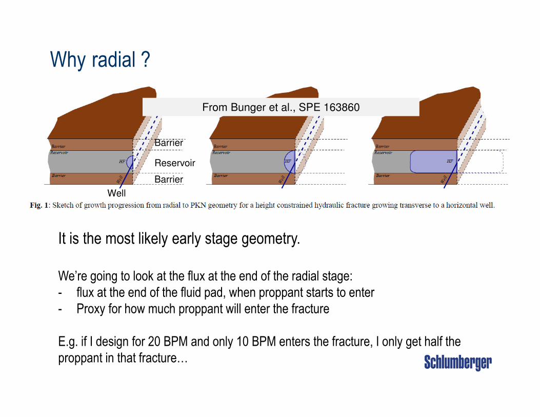
Why radial ?
It is the most likely early stage geometry.
We’re going to look at the flux at the end of the radial stage:
- flux at the end of the fluid pad, when proppant starts to enter
- Proxy for how much proppant will enter the fracture
E.g. if I design for 20 BPM and only 10 BPM enters the fracture, I only get half the
proppant in that fracture…
Barrier
Barrier
Reservoir
Well
From Bunger et al., SPE 163860
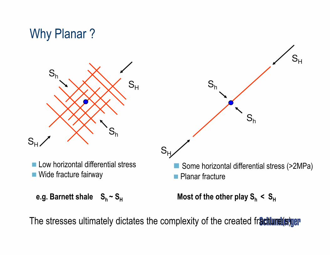
� Low horizontal differential stress
� Wide fracture fairway� Some horizontal differential stress (>2MPa)
� Planar fracture
SH
SH
Sh
ShSH
SH
Sh
Sh
The stresses ultimately dictates the complexity of the created fracture(s)
Why Planar ?
e.g. Barnett shale Sh ~ SH Most of the other play Sh < SH

Hydraulic fracture mechanics – in a nutshell
Fracture surface creation
Fluid flow
Solid deformation
• Mass balance: injected fluid = storage + leakoff
• Energy balance: Dissipations
stored in the rock
In-situ
stress
Very different propagation regimes depending on the
dominant mechanisms (e.g. Viscosity vs Toughness)[e.g. Detournay, 2004; Garagash 2000, 2009]
[Garagash et al., 2011]

A non-local, highly non-linear, time-dependent, moving boundary problem
• Elasticity
• Fluid continuity
• Poiseuille’s law
• Leak-off
• Boundary conditions
• Fracture Propagation (mode I)
Assumption of zero fluid lag valid for
[Garagash & Detournay, 2000]
[Desroches et al. 1993;
Garagash et al.,2000, 2011;
Bunger & Detournay 2008]inner lefm asymptote outer viscosity asymptote
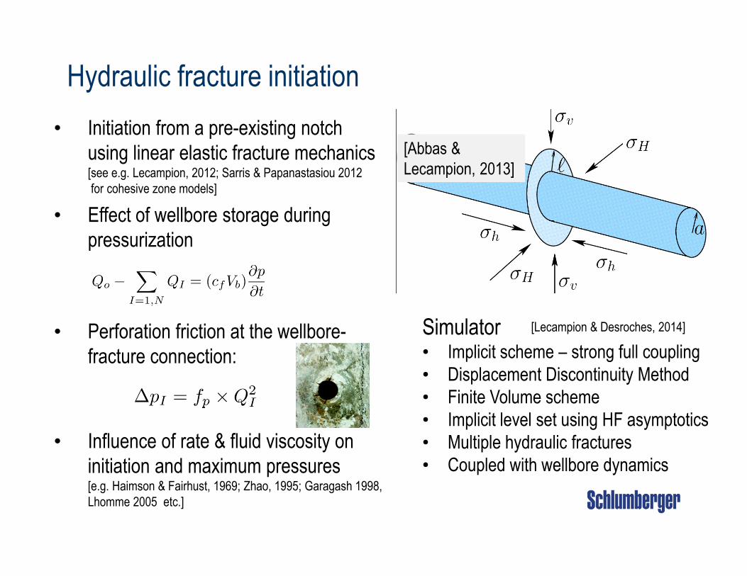
Hydraulic fracture initiation
• Initiation from a pre-existing notch
using linear elastic fracture mechanics[see e.g. Lecampion, 2012; Sarris & Papanastasiou 2012
for cohesive zone models]
• Effect of wellbore storage during
pressurization
• Perforation friction at the wellbore-
fracture connection:
• Influence of rate & fluid viscosity on
initiation and maximum pressures[e.g. Haimson & Fairhust, 1969; Zhao, 1995; Garagash 1998,
Lhomme 2005 etc.]
Simulator• Implicit scheme – strong full coupling
• Displacement Discontinuity Method
• Finite Volume scheme
• Implicit level set using HF asymptotics
• Multiple hydraulic fractures
• Coupled with wellbore dynamics
[Lecampion & Desroches, 2014]
[Abbas &
Lecampion, 2013]
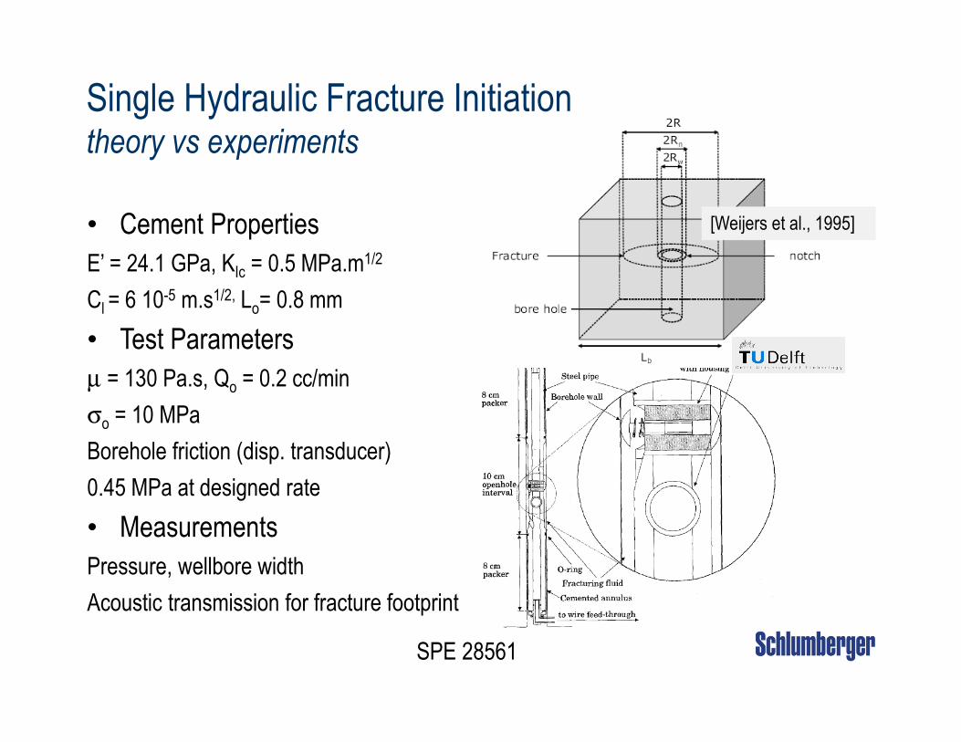
SPE 28561
[Weijers et al., 1995]
Single Hydraulic Fracture Initiationtheory vs experiments
• Cement Properties
E’ = 24.1 GPa, KIc = 0.5 MPa.m1/2
Cl = 6 10-5 m.s1/2, Lo= 0.8 mm
• Test Parameters
µ = 130 Pa.s, Qo = 0.2 cc/min
σo = 10 MPa
Borehole friction (disp. transducer)
0.45 MPa at designed rate
• Measurements
Pressure, wellbore width
Acoustic transmission for fracture footprint

Theory vs experiments – TU Delft cov12c experiment
[Lecampion et al., ISRM 2015]

Multiple HFs growth – “Stress shadow” vs “limited entry”
Uniformly heated plate to 52C, then cooled from one edge
Initial 1.6mm wide notches, regularly spaced (N=18).
[Geyer & Nemat-Nasser, 1982]
Growth of parallel (dry) cracks in glass
• Viscous forces may dampen the effect of stress interference
• Perforations at each fracture entrance (Bernouilli-like nozzles) will
surely modify the system dynamics (limited entry).

# 1
# 2
# 3
Example of 3 fractures 50ft apart
without perforation friction
Kicks in when Spacing ≈ Height or Length
# 1, #3
# 1, #3
# 2
# 2
Middle fracture is shut down…
“Stress Shadow” versus ”Limited Entry”

# 1 # 2 # 3
Example of 3 fractures 50ft apart
with 200 psi perforation friction
# 1, #3
# 2
Even flux for all fractures…
“Stress Shadow” versus ”Limited Entry”
Kicks in when Spacing ≈ Height or Length
[Lecampion, Desroches 2014]

A ‘typical’ horizontal well: local variations of in-situ stresses
• 7000ft TVD
• N = 4 fractures
• Spacing 50 ft
• Injection Rate 18BPM * 4 = 72 BPM
• Perforations:
• ½” diameter
• C=0.6 (discharge coef.)
In-situ stress heterogeneities on
the different fractures
– 34 MPa – 37 MPa
– 35.6 MPa – 38 MPa

Uniform perforation friction – 250psi pressure drop
a stage with 4 fractures with different in-situ stress (everything else uniform)
7000
6800
7200 Flo
w r
ate
in (
BP
M)
Time (sec.)
What if you don’t know the stress variation along the lateral?
4th fracture does NOT initiate!
[Lecampion, Desroches 2014]

Designing out the effect of stress heterogeneities?
Engineered perfs friction – choking down clusters with lower stress
a stage with 4 fractures with different in-situ stress (everything else uniform)
7000
6800
7200
Time (sec.)
Flo
w r
ate
in (
BP
M)
[Lecampion, Desroches 2014]

e.g. what if the surface rate is lower ? (Surface rate = 2/3 designed)
a stage with 4 fractures with different in-situ stress (everything else uniform)
This is not robust !
Time (sec) Time (sec)
Fra
ctur
e le
ngth
(ft)
Flo
w r
ate
In (
BP
M)
4th fracture does NOT initiate!
[Lecampion, Desroches 2014]

i) Initiation of multiple fractures
from the # perforations[Van der Ketterij et al., 1997 ]
σh
σ
H
σ
v
Extra NWB
closure stress
ii) link-up to form a single
fracture in the “far-field”
→ an extra near-wellbore pressure drop and
an extra near-wellbore closure stress.
It is even worse in practice: near wellbore fracture tortuosity

i) Initiation of multiple fractures
from the # perforations
[Van der Ketterij et al., 1997 ]
σh
σ
H
σ
v
Extra NWB
closure stress
ii) link-up to form a single
fracture in the “far-field”
→ an extra near-wellbore pressure drop and
an extra near-wellbore closure stress.
It is even worse in practice: near wellbore fracture tortuosity
[Weng, 1992]

Single entry fracturing – Field experiment
One fracture at a time (single entry fracturing)
Robustness in the amount of proppant placed
Competition between growing fractures is not a problem
anymore
Completion technology: Coil Tubing activated sleeves

Rowell-Chandler – single entry field experiment
Eagle Ford Shale
Goal: Place 92 fractures, 65ft apart
Same treatment throughout
14 diagnostic stages (step-downs ...)
Very homogeneous formation…MD (ft)
Fracture Gradient from
DRIFTS
(PS
I/ft)
[Desroches et al., 2014 SPE171667]
Well drilled in the direction of Sh
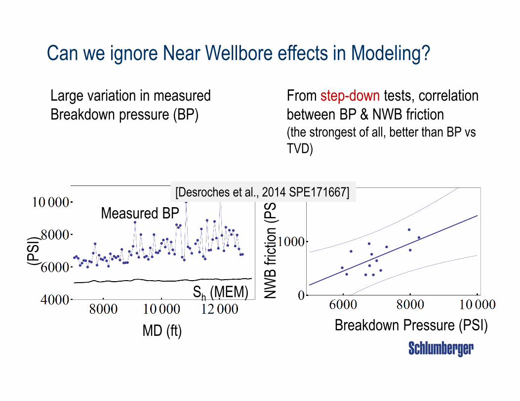
Can we ignore Near Wellbore effects in Modeling?
Large variation in measured
Breakdown pressure (BP)
From step-down tests, correlation
between BP & NWB friction (the strongest of all, better than BP vs
TVD)
R2 =0.7
MD (ft)
(PS
I)
Sh (MEM)
Measured BP
Breakdown Pressure (PSI)
NW
B fr
ictio
n (P
SI)[Desroches et al., 2014 SPE171667]
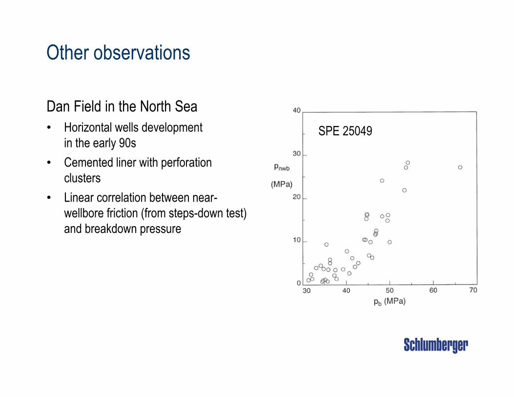
Other observations
Dan Field in the North Sea
• Horizontal wells development
in the early 90s
• Cemented liner with perforation
clusters
• Linear correlation between near-
wellbore friction (from steps-down test)
and breakdown pressure
SPE 25049

Rowell-Chandler – single entry field experimentEagle Ford Shale – Model Calibration
Calibration of the near-wellbore stress to match measured breakdown pressure
All the remaining parameters from characterization & treatment data
MD (ft)
(PSI)
Adjusted Sh
Matched Breakdowns
[Desroches et al., 2014 SPE171667]

What if we had done a “plug & perf” – 4 clusters?
Proppant transport is extremely poor with slickwater for rate below 15BPM
(settling even in the pipe).
Flow rate in (BPM)
Cluster
Flo
w r
ate
in (
BP
M)
31% cluster < 10BPM
29% cluster > 30BPM
Only 26% clusters
within 5 BPM
of the designed rate!
[Desroches et al., 2014 SPE171667]
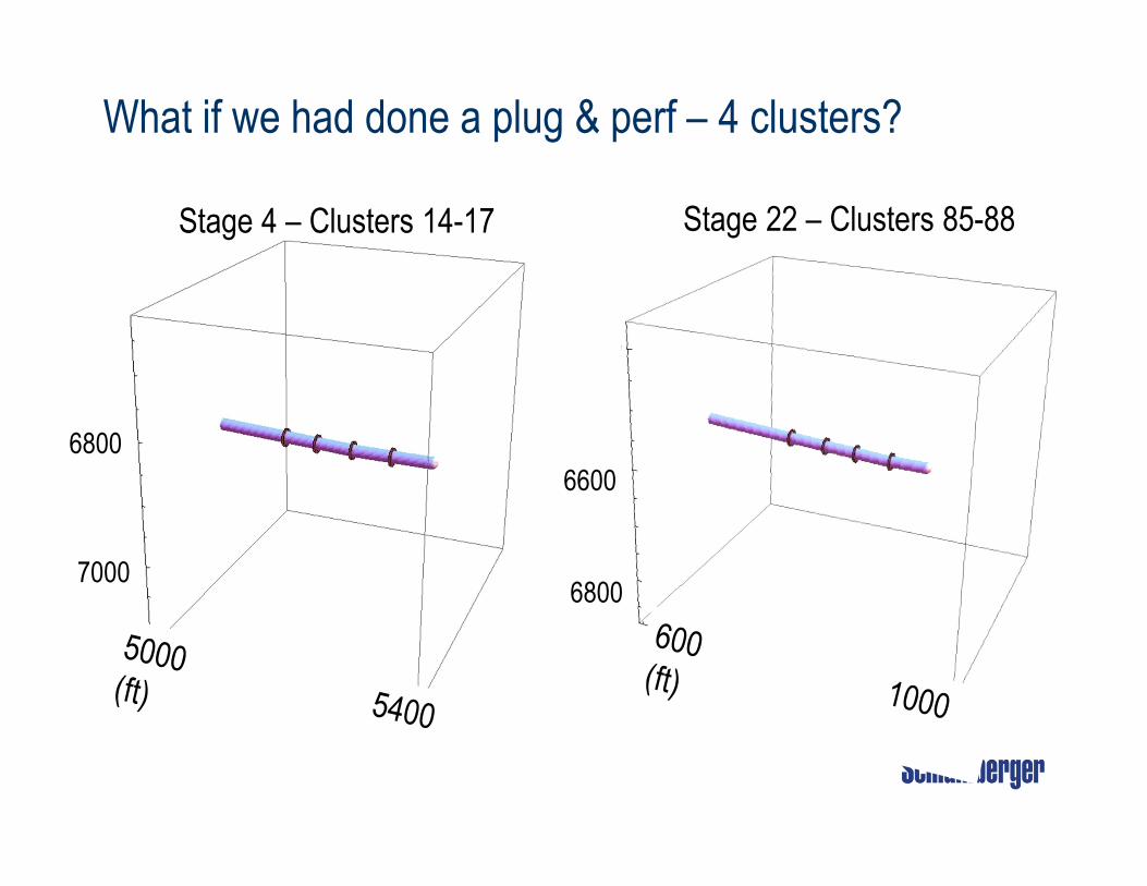
What if we had done a plug & perf – 4 clusters?
Stage 22 – Clusters 85-88 Stage 4 – Clusters 14-17
6800
70006800
6600

Summary
• Hydraulic fracturing theory is predictive (for simple fracture geometry).
• First simulator combining initiation & propagation of multiple radial hydraulic fractures
• Simultaneous fracture placement is inherently not robust
• Combination of initiation & propagation
• Engineered perforation friction design can counterbalance stress interference• But it is not very robust in the presence of typical heterogeneities
• A large heterogeneity in near-wellbore tortuosity exists
• We can’t predict it
• In a multi-cluster setting, it strongly affects fluid intake of the fractures(and proppant distribution, and production)
• Fracture optimization is thus not straightforward: no fracture follows the design…
• Single-entry is a simple tool to:
• diagnose that issue
• optimize the pumping schedule for a single fracture
• make informed decisions on how to proceed further
Selected References• Bunger, A. & Peirce, A. Numerical Simulation of Simultaneous Growth of Multiple Interacting Hydraulic Fractures from Horizontal Wells ASCE
Shale Energy Engineering Conference, 2014
• Bunger, A. Analysis of the Power Input Needed to Propagate Multiple Hydraulic Fractures Int. J. Sol. Struct., 2013, 50, 1538-1549
• Desroches, J.; Detournay, E.; Lenoach, B.; Papanastasiou, P.; Pearson, J.; Thiercelin, M. & Cheng, A. The crack tip region in hydraulic
fracturing Proceedings of the Royal Society of London. Series A: Mathematical and Physical Sciences, The Royal Society, 1994, 447, 39
• J. Desroches, B. Lecampion, H. Ramakrishnan, R. Prioul and E. Brown, Benefits of Controlled Hydraulic Fracture Placement: Theory and
Field Experiment SPE-171667 presented at the SPE/CSUR Unconventional Resources Conference—Canada held in Calgary, Alberta,
Canada, 30 September–2 October 2014.
• Garagash, D. & Detournay, E. The tip region of a fluid-driven fracture in an elastic medium J. Appl. Mech., 2000, 67, 183-192
• Garagash, D. I.; Detournay, E. & Adachi, J. Multiscale tip asymptotics in hydraulic fracture with leak-off Journal of Fluid Mechanics, 2011,
669, 260-297
• B. Lecampion and J. Desroches. Simultaneous initiation and propagation of multiple transverse hydraulic fractures in a horizontal well. In 48th
US Rock Mechanics/Geomechanics Symposium, Mpls, MN, USA, 1–4 June 2014. ARMA 14-7110.
• Lecampion, B.; Peirce, A.; Detournay, E.; Zhang, X.; Chen, Z.; Bunger, A.; Detournay, C.; Napier, J.; Abbas, S.; Garagash, D. & Cundall, P.
The impact of the near-tip logic on the accuracy and convergence rate of hydraulic fracture simulators compared to reference solutions in
The International Conference for Effective and Sustainable Hydraulic Fracturing, May 20-22, Brisbane, Australia, 2013.
• B. Lecampion. Hydraulic fracture initiation from an open-hole: Wellbore size, pressurization rate and fluid-solid coupling effects. In 46th U.S.
Rock Mechanics/Geomechanics Symposium, number ARMA 2012-601, June 24–27 2012.
• Peirce, A. P. & Detournay, E. An implicit level set method for modeling hydraulically driven fractures Computer Methods in Applied Mechanics
and Engineering, 2008, 197, 2858-2885
• Savitski, A. & Detournay, E. Propagation of a penny-shaped fluid-driven fracture in an impermeable rock: asymptotic solutions International
Journal of Solids and Structures, 2002, 39, 6311-6337
• van de Ketterij, R. G. & de Pater, C. J. Experimental study on the impact of perforations on hydraulic fracture tortuosity
SPE European Formation Damage Conference, 1997