evaluation of the larch/vhdl interactive prover in
TRANSCRIPT
RL-TR-97-123 In-House Report October 1997
EVALUATION OF THE LARCH/VHDL INTERACTIVE PROVER IN HARDWARE VERIFICATION
Robert J. Paragi, Michael P. Nassif and Edward P. Stabler
APPROVED FOR PUBLIC RELEASE; D/STR/BUTION UNLIMITED.
19980223 110
Rome Laboratory Air Force Materiel Command
Rome, New York
[»TIC QUALTT7 INSPECTED 3
This report has been reviewed by the Rome Laboratory Public Affairs Office (PA) and is releasable to the National Technical Information Service (NTIS). At NTIS it will be releasable to the general public, including foreign nations.
RL-TR-97-123 has been reviewed and is approved for publication.
APPROVED: 0^/2MJL C, pj
EUGENE C. BLACKBURN Chief, Electronics Reliability Division Electromagnetics & Reliability Directorate
FORTHEDIRECTOR^^t^Y B*U^P v JOHN J. BART, Chief Scientist
Reliability Sciences
If your address has changed or if you wish to be removed from the Rome Laboratory mailing list, or if the addressee is no longer employed by your organization, please notify Rome Laboratory/ERDD, Rome, NY 13441. This will assist us in maintaining a current mailing list.
Do not return copies of this report unless contractual obligations or notices on a specific document require that it be returned.
REPORT DOCUMENTATION PAGE Form Approved OMB No. 0704-0188
Public reporting burden for this collection of information is estimated to average 1 hour per response, including the time for reviewing instructions, searching existing data sources, gathering and maintaining the data needed, and completing and reviewing the collection of information. Send comments regarding this burden estimate or any other aspect of this collection of information, including suggestions for reducing this burden, to Washington Headquarters Services, Directorate for Information Operations and Reports, 1215 Jefferson Davis Highway, Suite 1204, Arlington, VA 22202-4302, and to the Office of Management and Budget, Paperwork Reduction Project (0704-0188), Washington, DC 20503.
1. AGENCY USE ONLY (Leave blank) 2. REPORT DATE
October 1997 3. REPORT TYPE AND DATES COVERED
In-House 4. TITLE AND SUBTITLE
EVALUATION OF THE LARCH/VHDL INTERACTIVE PROVER IN HARDWARE VERIFICATION 6. AUTHOR(S)
Robert J. Paragi, Michael P. Nassif, and *Edward P. Stabler
5. FUNDING NUMBERS
PE-62702F PR - 2338 TA-01 WU-8V
7. PERFORMING ORGANIZATION NAME(S) AND ADDRESS(ES)
Rome Laboratory/ERDD 525 Brooks Road Rome, NY 13441-4505
8. PERFORMING ORGANIZATION REPORT NUMBER
RL-TR-97-123
9. SPONSORING/MONITORING AGENCY NAME(S) AND ADDRESS(ES)
Rome Laboratory/ERDD 525 Brooks Road Rome, NY 13441-4505
10. SPONSORING/MONITORING AGENCY REPORT NUMBER
RL-TR-97-123
11. SUPPLEMENTARY NOTES
* Dept of ECE, Syracuse University. Rome Laboratory Project Engineer: Robert J. Paragi/ERDD/315-330-3547
12a. DISTRIBUTION AVAILABILITY STATEMENT
Approved for public release; distribution unlimited.
12b. DISTRIBUTION CODE
13. ABSTRACT (Maximum 200 words!
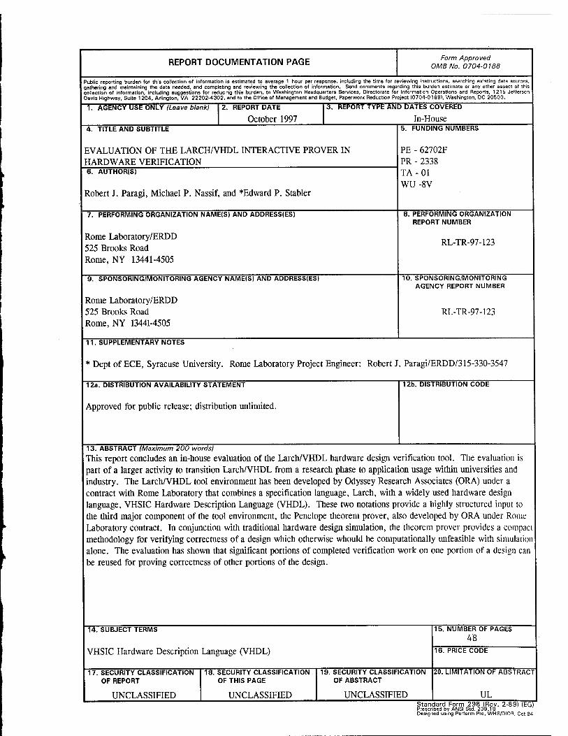
This report concludes an in-house evaluation of the Larch/VHDL hardware design verification tool. The evaluation is part of a larger activity to transition Larch/VHDL from a research phase to application usage within universities and industry. The Larch/VHDL tool environment has been developed by Odyssey Research Associates (ORA) under a contract with Rome Laboratory that combines a specification language, Larch, with a widely used hardware design language, VHSIC Hardware Description Language (VHDL). These two notations provide a highly structured input to the third major component of the tool environment, the Penelope theorem prover, also developed by ORA under Rome Laboratory contract. In conjunction with traditional hardware design simulation, the theorem prover provides a compact methodology for verifying correctness of a design which otherwise whould be computationally unfeasible with simulation alone. The evaluation has shown that significant portions of completed verification work on one portion of a design can be reused for proving correctness of other portions of the design.
14. SUBJECT TERMS
VHSIC Hardware Description Language (VHDL)
15. NUMBER OF PAGES 48
16. PRICE CODE
17. SECURITY CLASSIFICATION OF REPORT
UNCLASSIFIED
18. SECURITY CLASSIFICATION OF THIS PAGE
UNCLASSIFIED
19. SECURITY CLASSIFICATION OF ABSTRACT
UNCLASSIFIED
20. LIMITATION OF ABSTRACT
UL Standard Form 298 (Rev. 2-89) (EG) Prescribed by ANSI Std. 239.18 Designed using Perform Pro. WHS/DIOR, Oct 94
Table of Contents
Introduction 3 Background 4
Combining Specifications and Proofs 9 Applications 11 Verification at Multiple Levels 11 Terminology and Example Design 12 Applying the Penelope Theorem Prover 12
TheMTP 14 Instruction Set Architecture Property Proofs 15 Register Level Property Proofs 24 Conclusions about Verification at Multiple Levels 27
Conclusions 29 Bibliography 31 Appendix A: Multiple Technology Processor (MTP) 33 ALU VHDL Description 33 Appendix B: Multiple Technology Processor (MTP) Specification 37
Table of Figures
FIGURE 1 DESIGN ENVIRONMENT 9 FIGURE 2 THE LARCH/VHDL VERIFICATION PROCESS 11 FIGURE 3 MTP BLOCK DIAGRAM 14 FIGURE 4 ALU IF-THEN-ELSE CHAIN 23 FIGURE 5 VERIFYING VHDL DESIGNS 25 FIGURE 6 GRAPHICALLY-ASSISTED DESIGN PROCESS 26
Table of Listings
LISTING 1 SPECIFICATION OF THE ISA MODEL 21
Table of Tables
TABLE 1 VARIABLES FOR EXAMPLE AT ISA LEVEL 22 TABLE 2 MTP INSTRUCTION SET ARCHITECTURE 39
1/2

Introduction
This technical report summarizes an evaluation of the Larch/VHDL hardware design
verification tool environment. The tool evaluation is based upon the formal verification
of the Multi-Technology Processor (MTP) design.
A Larch/VHDL tool environment has been developed by Odyssey Research
Associates (ORA) under contract with Rome Laboratory. The tool combines a
specification language, Larch [2], with a widely used hardware design language, VHSIC
Hardware Description Language (VHDL) [14]. These two notations provide a highly
structured input to the third major component of the tool environment, the Penelope
theorem prover, also developed by ORA under contract with Rome Laboratory. The
purpose of this in-house effort is to evaluate the Larch/VHDL hardware design
verification tool for usability and soundness. The evaluation is part of a larger activity to
transition Larch/VHDL from a research phase to application usage within universities
and industry. The VHDL application model used for the evaluation is the Multiple
Technology Processor (MTP), a 32-bit integer arithmetic and logic unit (ALU) with a
register file. (See Appendix B.) Verification of the MTP included checking ALU results
and checking register flag settings for arithmetic overflow, zero-result, and conditional
instruction execution. Results of symbolically executing many instructions on the MTP
model have been verified as correct. Further, detailed properties of instruction execution
(correct ALU results for arithmetic and logical operations, plus correct flag settings for
overflow, conditional operation results, and zero-result) have been verified against a
VHDL register transfer level model of the MTP. Of the 26 MTP instructions, 21 have
been verified to this level.
Background
The Larch/VHDL verification environment is a combination of Larch, VHDL, and
the Penelope theorem prover. Larch is a two-tiered specification language developed at
the Massachusetts Institute of Technology (MIT). The first tier, the Larch Shared
Language (LSL) [4], is a first order predicate calculus used to build the traits, or theories,
that define the sorts (VHDL types) used by the target language, i.e., bit, word, string,
arrays, integer, function, etc. The second tier, called the interface language [2], defines
the communication mechanisms of the target language, Ada, C, C++ or in this case
VHDL, in the Larch notation. LSL is used to mathematically model data objects and
operations on those objects, while the interface language maps the VHDL model into the
abstractions represented by the Larch expressions for the purpose of formal reasoning.
VHDL evolved in part from a subset of the general purpose programming language
Ada, and has been extended with capabilities to describe complex timing situations in
hardware designs [14].
Larch/VHDL is an interactive environment that helps its user to develop and verify
digital electronic hardware designs written in VHDL. Larch/VHDL is well suited to
developing code in the goal-directed style advocated by Gries [3] and Dijkstra [1]. In
this style the designer develops a VHDL model from a specification in a way that assures
the VHDL model will meet the specification.
In order to verify a large design, we will want to decompose the design into
manageable pieces (even if we do not want to, we will be forced to) that we can specify
and verify separately. These pieces will need to be combined to form the full design and
the way the pieces interact will have to be rigidly defined to enable us to reason about the
combined system. To be useful, this decomposition process should be fully hierarchical
so that the pieces can be further decomposed. To do this kind of decomposition in a
disciplined way we will therefore need all the machinery that is provided by the entities,
ports, component instantiations, port maps, etc. provided by a hardware description
language like VHDL. To reason about how the state of the design evolves in time, we
will want to reason about when individual pieces of data change and how long they have
been stable, so we need the equivalents of the signals, events, stable, delayed, etc.
provided by VHDL. Typical mathematical structuring constructs such as parameterized
Larch traits or parameterized theories in PVS (a theorem prover generally used to verify
consistency of requirements specifications) are not directly applicable to such needs.
In short, since all the machinery of an HDL is needed to verify a large design, it
makes sense to use an existing well designed language like VHDL to organize the
verification effort rather than reinvent such machinery inside a mathematical language.
Of course, we can use verified designs written in VHDL to communicate the design to
other tools for simulation, synthesis, and layout. This is a beneficial feature of an HDL
based verification system but it is not the main reason for choosing this approach. The
main goal is specification and verification of designs independent of how they are
described, but we claim that the structure provided by the HDL is essential to achieving
this goal, so we might as well make use of the hardware description language for these
other tasks as well.
The advantage of starting with a specification (in this case written in Larch) is that the
specification is precise and compact. Also, in a hierarchical design process, the higher
level designs may be refined to specifications of components. This allows for each
refinement to be traced back to the original specification for compliance, i.e. verification.
The integration of Larch and VHDL provides a path from specification to
implementation.
The Larch/VHDL environment includes a large body of traits that define the basic
constructs of digital design such as bit, vector, gate, logic operations and so on. Traits
define sorts (logical types, including functions) and state properties or assertions that
must hold true. Traits also contain theorems which are statements that are deducible
from assertions, previously deduced theorems, and/or the assertions or theorems of other
traits that are included. The two-tiered Larch approach allows designers the capability to
extend the library of traits in order to support user defined sorts in their models. Once
implemented, the traits are available as library components for reuse in other
applications.
Traits are used to capture the concepts and relationships used in digital design, such as
arithmetic, arrays, and lists. To support VHDL semantics there are traits defining
signals, and signal delay, and other concepts needed to express the semantics of VHDL.
Traits also describe the relationship between bit level operations and their arithmetic
interpretation, in twos-complement or unsigned bit-level representations.
The Penelope theorem prover was originally developed for proving the correctness of
Ada procedures. It is the purpose of the Penelope theorem prover to assist the user in
proving theorems from the supplied axioms and included traits by applying logic
reduction rules according to user directions and indicates to the user what, if anything,
still has to be proved after each step. Penelope includes a simple proof editor/checker for
predicate calculus that provides a number of proof rules for performing simplification
and proofs.
6
ORA would like Penelope to automatically simplify the logic conditions that it
computes, and to automatically prove the verification conditions if possible.
Unfortunately, all but the most trivial simplification and proofs in Penelope require the
guidance and control of the user. This interaction is necessary because of the well-
known fact that simplification and theorem proving are in general undecidable; even so
called automatic theorem provers usually require a good deal of guidance from human
beings.
The motivation for developing this type of verification tool environment is that it is
infeasible to exhaustively simulate all possible combinations of inputs to hardware
designs because the design complexity and data path widths have increased. Our goal
was to develop a formal verification tool that complements the current (simulation-
based) hardware design process.
The Larch/VHDL verification process augments the design process in four ways:
1. By developing Larch specifications which are independent of technology and
implementation details:
A. Specifications are unambiguous, concise and immune to errors in translation
from one natural language to another.
B. Specifications may be proven to be correct.
C. Specifications may be combined to form new specifications.
D. Specifications may be implemented in hardware or software.
2. By verifying the correctness of a VHDL model.
7
Determining the correctness of a design by exhaustive simulation is not a feasible
methodology due to the cost and time required to generate the test vector set and
simulate the model. Formal verification of a hardware design can increase the
designer's confidence that a digital circuit satisfies certain properties by reasoning
over every possible input condition.
3. By verifying multiple implementations of a design in VHDL.
In many cases, several VHDL architectures may be developed in order to perform
trade-off analysis. While multiple architectures will conform to the same entity
interface, their hardware implementations will vary in cost, area or performance.
4. By supporting hierarchical verification.
The Larch/VHDL methodology supports a form of verification of single components
or cells of a design which is done earlier in the development cycle than simulation is
typically done. Once verified, these components are available for reuse in other
designs.
Figure 1 shows the relations among VF1DL designs and Larch specifications in the
design hierarchy. The figure is separated vertically into three levels. The topmost level
represents the final product of the design activity. Proceeding from the highest level of
abstraction to lowest, boxes on the left side of the figure represent VHDL
entity/architecture pairs, and a design's hierarchical decomposition. This path represents
the actual design's hierarchy. The right side of the figure tracks the left side's
development, augmented with Larch specifications. At each level the entity establishes
8
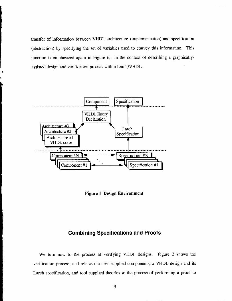
transfer of information between VHDL architecture (implementation) and specification
(abstraction) by specifying the set of variables used to convey this information. This
junction is emphasized again in Figure 6, in the context of describing a graphically-
assisted design and verification process within Larch/VHDL.
Component Specification
Architecture #3 I
VHDL Entity Declaration
Architecture #2 / Architecture #1
VHDL code
I Com Component #N I"
Component #1 h*
V Larch Specification S
Specification #N I •*-|SpeciJ
Specification #1
Figure 1 Design Environment
Combining Specifications and Proofs
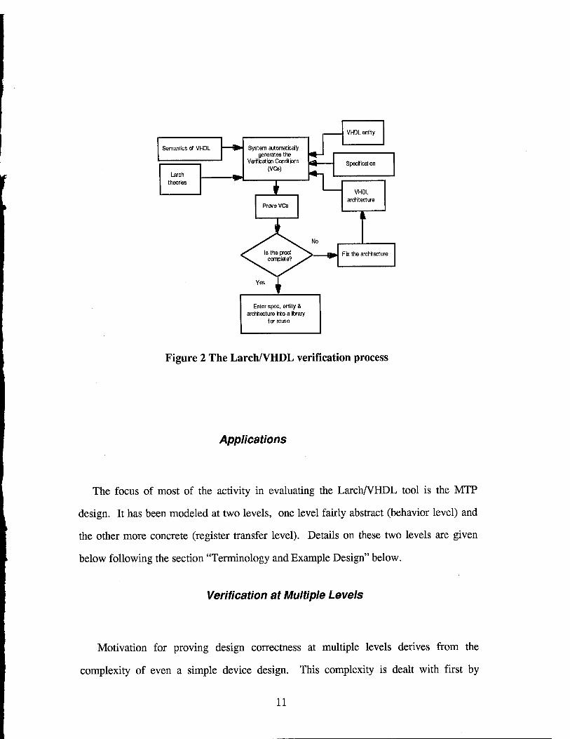
We turn now to the process of verifying VHDL designs. Figure 2 shows the
verification process, and relates the user supplied components, a VHDL design and its
Larch specification, and tool supplied theories to the process of performing a proof to
verify correctness of the design. On the top right of Figure 2 are VHDL designs and the
associated Larch specifications. A set of tool supplied theories (the top left of Figure 2)
defines design attributes, such as bit vectors, that have a purpose common to all designs.
ORA has developed a formal semantics of VHDL composed of definitions of VHDL
constructs in the Larch notation, such as timing and state. Larch theories (also called
"traits") are essentially self-contained sets of theorems that form a foundation in the
general mathematics of sets, elementary constructs in the integers, bit vector
manipulations, and conversion of bit vectors to integers for twos-complement integer
arithmetic with truncation. These theories are organized as libraries and form the
foundation for reasoning about designs.
The total collection of Larch theories is far more extensive than was needed for this
in-house effort. Other Larch theories available cover specifications for hardware designs
in VHDL and several areas of mathematics useful in general purpose logic and computer
science.
Larch/VHDL uses the VHDL semantics, Larch theories, and VHDL design
information (entity and architecture) as input and produces the verification conditions
("VC's", shown in the top center of Figure 2) as output for the user to prove. The VC's
must be proved to be correct using the Penelope theorem prover.
The actual proof process is iterative. If the proof attempt is not successful the user
modifies the specification or the VHDL architecture, and the VC's are automatically
regenerated. The user begins again to interactively prove the revised VC's.
10
Semantics of VHDL
r Larch theories
System automat'cally generates the
Verification Conditions (VCs)
I
VHDL entity
Specificat'on
n^ Prove VCs
VHDL architecture
Fix the architecture
Enter spec, entity & architecture into a Ibrary
for reuse
Figure 2 The Larch/VHDL verification process
Applications
The focus of most of the activity in evaluating the Larch/VHDL tool is the MTP
design. It has been modeled at two levels, one level fairly abstract (behavior level) and
the other more concrete (register transfer level). Details on these two levels are given
below following the section "Terminology and Example Design" below.
Verification at Multiple Levels
Motivation for proving design correctness at multiple levels derives from the
complexity of even a simple device design. This complexity is dealt with first by
11
describing the device's architecture from the perspective of someone programming the
device with assembly language, a perspective somewhat removed from the details of
ALU operation and data paths. The assembly language view verification of correctness
is performed within this model and is intended to find conceptual errors early in the
design process. A more detailed view at a lower level is provided from the hardware
designer's perspective. At this level errors which can affect the operation of a smaller
part of the design can be found.
Terminology and Example Design
The following discussion is focused on digital logic, whether considered as an
expression of a device's purpose or as a collection of logic gates, "the design", while a
VHDL description of a design is known as a "model".
Properties of a model of a digital logic hardware design can be expressed at more than
one level of detail: Instruction Set Architecture (ISA), behavioral, or Register Transfer
Level (RTL). "Behavioral" design properties are those that are typically generated from
the requirements of the intended user of the system. Behavioral properties generally are
informal, and state functional requirements in natural language. The requirements are
then translated into the language of some formal specification system. The process from
here forward is one of trying to match a requirements property with one or more
properties of the model to determine if the requirement is met within the model. The
process has often been described as checking to see if the implementation (model) meets
(implies) the specification (requirements).
Applying the Penelope Theorem Prover
12
1
In the context of a VHDL design, the original proof obligation is the Verification
Condition (VC) (Figure 2), which is generated automatically by the Larch/VHDL tool.
During the proof process the original proof property (VC) considered as an obligation is
converted by each proof step into another proof obligation. A proof is complete when
there is no remaining proof obligation. The proof ends with "BY synthesis of TRUE" or
"BY analysis of FALSE".
In most sequences of proof steps assumptions are involved, and they are designated
"hypotheses". The "conclusion" (symbolically, "hypotheses" -> "conclusion") based on
these hypotheses is a proof obligation. Formally, the conjunction ("anding" together) of
the hypotheses implies the conclusion.
A property could be an axiom, a basic assumption, usually about some physical
situation, where following the keyword "asserts" are axioms about writing and reading
memories, plus an axiom particular to the register file of a design described below.
A VHDL entity defines the input and output signals for a design, and exists as a file
apart from the VHDL architecture that contains design implementation details. The
physical separation of entity and architecture allows association of multiple architectures
to a single entity. Specifications relate to VHDL directly at the entity declaration by
referencing variables listed in the entity interface file. In this view creating the entity is
the beginning of the formal design process, in that both the Larch-like specification and
the VHDL architecture follow from it. Just such a chronology is followed with graphical
assistance to the process of creating files and constructing proofs, as described below.
13
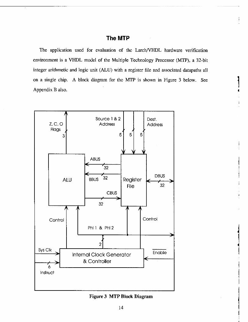
The MTP
The application used for evaluation of the Larch/VHDL hardware verification
environment is a VHDL model of the Multiple Technology Processor (MTP), a 32-bit
integer arithmetic and logic unit (ALU) with a register file and associated datapaths all
on a single chip. A block diagram for the MTP is shown in Figure 3 below. See
Appendix B also.
Z.C.O Flags /
ALU
A A
Control
Sys Clk
-7*-> 6
Instruct
Source 1 & 2 Address
ABUS "7*
32
BBUS 32
CBUS
■7* >l 32
Phi 1 & Phi 2
/ /
Y Y Y
Dest. Address
DBUS Register J^ y. ^
File 32
Control
Internal Clock Generator & Controller
Enable
Figure 3 MTP Block Diagram
14
The word "specification" is used often throughout this report in the context of the
MTP example, and refers to the formal logic descriptions of the MTP as developed from
the informal descriptions in English text, written in the Larch specification language.
Our approach is to describe and reason about the design at the level of integer arithmetic,
which is more intuitive to the user. Integer arithmetic is supported by twos-complement
arithmetic properties (subtraction implemented as addition), and to using bit-string ("bit-
vector") representations where bit-level operations are necessary. The use of bit-string
representations further requires reasoning about truncation of these strings to a fixed
width, as required by the precision of the targeted ALU and the width of data paths in the
design. In the actual proof reasoning about truncation and extreme values of integers
(overflow and underflow) invariably reduces to simplifying expressions containing
powers of two. Then the problem of completing the proof is back in the realm of integer
arithmetic.
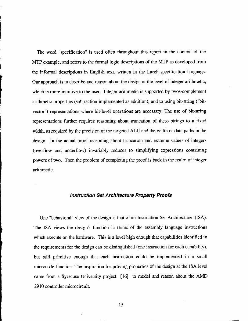
Instruction Set Architecture Property Proofs
One "behavioral" view of the design is that of an Instruction Set Architecture (ISA).
The ISA views the design's function in terms of the assembly language instructions
which execute on the hardware. This is a level high enough that capabilities identified in
the requirements for the design can be distinguished (one instruction for each capability),
but still primitive enough that each instruction could be implemented in a small
microcode function. The inspiration for proving properties of the design at the ISA level
came from a Syracuse University project [16] to model and reason about the AMD
2910 controller microcircuit.
15
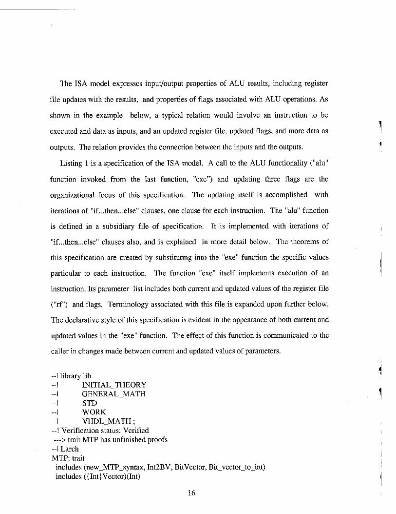
The ISA model expresses input/output properties of ALU results, including register
file updates with the results, and properties of flags associated with ALU operations. As
shown in the example below, a typical relation would involve an instruction to be
executed and data as inputs, and an updated register file, updated flags, and more data as
outputs. The relation provides the connection between the inputs and the outputs.
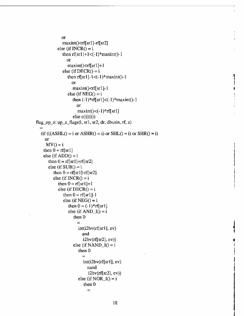
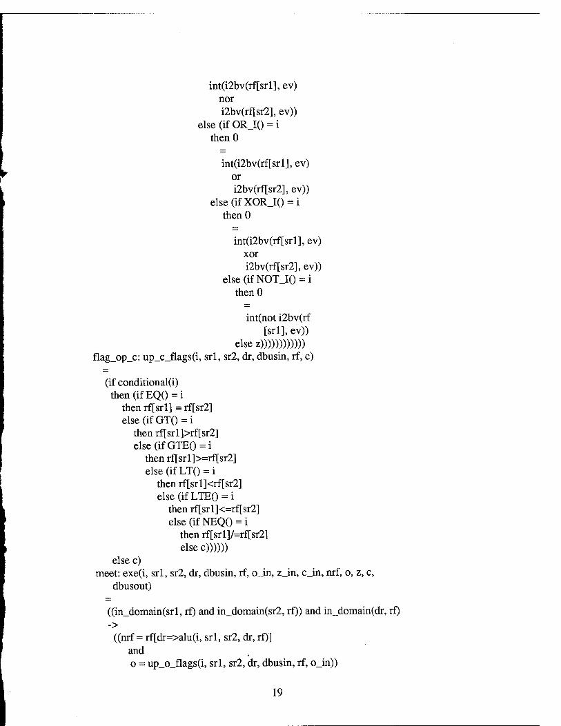
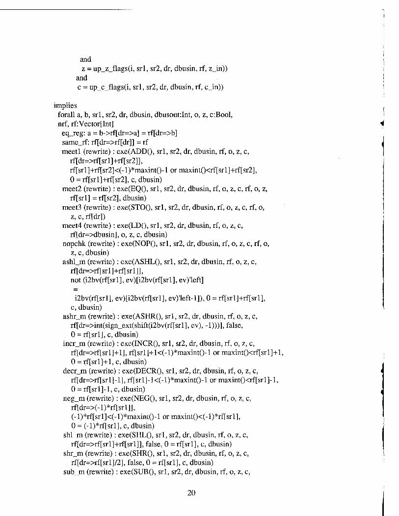
Listing 1 is a specification of the ISA model. A call to the ALU functionality ("alu"
function invoked from the last function, "exe") and updating three flags are the
organizational focus of this specification. The updating itself is accomplished with
iterations of "if...then...else" clauses, one clause for each instruction. The "alu" function
is defined in a subsidiary file of specification. It is implemented with iterations of
"if...then...else" clauses also, and is explained in more detail below. The theorems of
this specification are created by substituting into the "exe" function the specific values
particular to each instruction. The function "exe" itself implements execution of an
instruction. Its parameter list includes both current and updated values of the register file
("rf") and flags. Terminology associated with this file is expanded upon further below.
The declarative style of this specification is evident in the appearance of both current and
updated values in the "exe" function. The effect of this function is communicated to the
caller in changes made between current and updated values of parameters.
library lib INITIAL_THEORY GENERALJVIATH STD WORK VHDL JVIATH;
—! Verification status: Verified —> trait MTP has unfinished proofs
—I Larch MTP: trait
includes (new_MTP_syntax, Int2BV, BitVector, Bit_vector_to_int) includes ({Int} Vector)(Int)
16
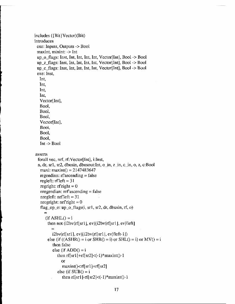
includes ({Bit}Vector)(Bit) introduces
exe: Inputs, Outputs -> Bool maxint, minint: -> Int up_o_flags: Inst, Int, Int, Int, Int, Vector[Int], Bool -> Bool up_z_flags: Inst, Int, Int, Int, Int, Vector[Int], Bool -> Bool up_c_flags: Inst, Int, Int, Int, Int, Vector[Int], Bool -> Bool exe: Inst,
Int, Int, Int, Int, Vector[Int], Bool, Bool, Bool, Vector[Int], Bool, Bool, Bool, Int -> Bool
asserts forall vec, nrf, rf: Vector [Int], i:Inst, n, dr, srl, sr2, dbusin, dbusout:Int, o_in, z_in, c_in, o, z, c:Bool
maxi: maxint() = 2147483647 regendian: rf ascending = false regleft:rfleft = 31 regright: rf right = 0 nregendian: nrf ascending = false nregleft: nrf left = 31 nregright: nrf right = 0 flag_op_o: up_o_flags(i, srl, sr2, dr, dbusin, rf, o)
(if ASHL()=i then not (i2bv(rf[srl], ev)[i2bv(rf[srl], ev)'left]
i2bv(rf[srl], ev)[i2bv(rf[srl], ev)'left-l]) else (if ((ASHRO = i or SHR() = i) or SHL() = i) or MV() = i
then false else (if ADD() = i
thenrf[srl]+rf[sr2]<(-l)*maxint()-l or maxint()<rf[srl]+rf[sr2]
else (if SUB() = i then rf[srl]-rf[sr2]<(-l)*maxint()-l
17
or maxint()<rf[srl]-rf[sr2]
else (iflNCRO = i then rf[srl]+l<(-l)*maxint()-l
or maxint()<rf[srl]+1
else(ifDECR() = i then rf[srl]-l<(-l)*maxint()-l
or maxint()<rf[srl]-l
else(ifNEG() = i then (-l)*rf[srl]<(-l)*maxint()-l
or maxint()<(-l)*rf[srl]
elseo))))))) flag_op_z: up_z_flags(i, srl, sr2, dr, dbusin, if, z)
(if (((ASHLO = i or ASHR() = i) or SHL() = i) or SHR() = i) or MV() = i
then 0 = rf[srl] else (if ADD()=i
then 0 = rf[srl]+rf[sr2] else (if SUB () = i
then 0 = rf[srl]-rf[sr2] else(ifINCR()=i
thenO = rf[srl]+l else(ifDECR() = i
thenO = rf[srl]-l else(ifNEG() = i
thenO = (-l)*rf[srl] else (if AND_I()=i
thenO
int(i2bv(rf[srl], ev) and i2bv(rf[sr2], ev))
else (if NAND_I() = i then 0
int(i2bv(rf[srl], ev) nand i2bv(rf[sr2], ev))
else(ifNOR_I() = i thenO
18
int(i2bv(rf[srl], ev) nor i2bv(rf[sr2], ev))
else(ifOR_I() = i thenO
int(i2bv(rf[srl], ev) or i2bv(rf[sr2], ev))
else(ifXOR_I() = i thenO
int(i2bv(rf[srl], ev) xor i2bv(rf[sr2], ev))
else(ifNOT_I() = i thenO
int(not i2bv(rf [srl], ev))
elsez)))))))))))) flag_op_c: up_c_flags(i, srl, sr2, dr, dbusin, rf, c)
(if conditional(i) then(ifEQ() = i
then rf[srl] = rf[sr2] else(ifGT() = i
then rf[srl]>rf[sr2] else(ifGTE() = i
then rf[srl]>=rf[sr2] else(ifLT() = i
then rf[srl]<rf[sr2] else(ifLTE() = i
then rf[srl]<=rf[sr2] else(ifNEQ() = i
then rf[srl]/=rf[sr2] elsec))))))
else c) meet: exe(i, srl, sr2, dr, dbusin, rf, o_in, z_in, c_in, nrf, o, z, c,
dbusout)
((in_domain(srl, rf) and in_domain(sr2, rf)) and in_domain(dr, rf) ->
((nrf = rf[dr=>alu(i, srl, sr2, dr, rf)] and o = up_o_flags(i, srl, sr2, dr, dbusin, rf, o_in))
19
and z = up_z_flags(i, srl, sr2, dr, dbusin, rf, z_in))
and c = up_c_flags(i, srl, sr2, dr, dbusin, rf, c_in))
implies forall a, b, srl, sr2, dr, dbusin, dbusout:Int, o, z, c:Bool, nrf, rf:Vector[Int]
eq_reg: a = b->rf[dr=>a] = rf[dr=>b] same_rf: rf[dr=>rf[dr]] = rf meetl (rewrite): exe(ADD(), srl, sr2, dr, dbusin, rf, o, z, c,
rf[dr=>rf[srl]+rf[sr2]], rf[srl]+rf[sr2]<(-l)*maxint()-l or maxint()<rf[srl]+rf[sr2], 0 = rf[srl]+rf[sr2], c, dbusin)
meet2 (rewrite): exe(EQ(), srl, sr2, dr, dbusin, rf, o, z, c, rf, o, z, rf[srl] = rf[sr2], dbusin)
meet3 (rewrite): exe(STO(), srl, sr2, dr, dbusin, rf, o, z, c, rf, o, z, c, rf[dr])
meet4 (rewrite): exe(LD(), srl, sr2, dr, dbusin, rf, o, z, c, rf[dr=>dbusin], o, z, c, dbusin)
nopchk (rewrite): exe(NOP(), srl, sr2, dr, dbusin, rf, o, z, c, rf, o, z, c, dbusin)
ashl_m (rewrite): exe(ASHL(), srl, sr2, dr, dbusin, rf, o, z, c, rf[dr=>rf[srl]+rf[srl]], not (i2bv(rf[srl], ev)[i2bv(rf[srl], ev)'left]
i2bv(rf[srl], ev)[i2bv(rf[srl], ev)'left-l]), 0 = rf[srl]+rf[srl], c, dbusin)
ashr_m (rewrite): exe(ASHR(), srl, sr2, dr, dbusin, rf, o, z, c, rf[dr=>int(sign_ext(shift(i2bv(rf[srl], ev), -1)))], false, 0 = rf[srl],c, dbusin)
incr_m (rewrite): exe(INCR(), srl, sr2, dr, dbusin, rf, o, z, c, rf[dr=>rf[srl]+l], rf[srl]+l<(-l)*maxint()-l or maxint()<rf[srl]+l, 0 = rf[srl]+l, c, dbusin)
decr_m (rewrite): exe(DECR(), srl, sr2, dr, dbusin, rf, o, z, c, rf[dr=>rf[srl]-l], rf[srl]-l<(-l)*maxint()-l or maxint()<rf[srl]-l, 0 = rf[srl]-l, c, dbusin)
neg_m (rewrite): exe(NEG(), srl, sr2, dr, dbusin, rf, o, z, c, rf[dr=>(-l)*rf[srl]], (-l)*rf[srl]<(-l)*maxint()-l or maxint()<(-l)*rf[srl], 0 = (-l)*rf[srl],c, dbusin)
shl_m (rewrite): exe(SHL(), srl, sr2, dr, dbusin, rf, o, z, c, rf[dr=>rf[srl]+rf[srl]], false, 0 = rf[srl], c, dbusin)
shr_m (rewrite): exe(SHR(), srl, sr2, dr, dbusin, rf, o, z, c, rf[dr=>rf[srl]/2], false, 0 = rf[srl], c, dbusin)
sub_m (rewrite): exe(SUB(), srl, sr2, dr, dbusin, rf, o, z, c,
20
rf[dr=>rf[srl]-rf[sr2]], rf[srl]-rf[sr2]<(-l)*maxint()-l or maxint()<rf[srl]-rf[sr2], 0 = rf[srl]-rf[sr2], c, dbusin)
and_m (rewrite): exe(AND_I(), srl, sr2, dr, dbusin, rf, o, z, c, rf[dr=>int(i2bv(rf[srl], ev) and i2bv(rf[sr2], ev))], o, 0 = int(i2bv(rf[srl], ev) and i2bv(rf[sr2], ev)), c, dbusin)
gt_m (rewrite): exe(GT(), srl, sr2, dr, dbusin, rf, o, z, c, rf, o, z, rf[srl]>rf[sr2], dbusin)
gte_m (rewrite): exe(GTE(), srl, sr2, dr, dbusin, rf, o, z, c, rf, o, z, rf[srl]>=rf[sr2], dbusin)
lt_m (rewrite): exe(LT(), srl, sr2, dr, dbusin, rf, o, z, c, rf, o, z, rf[srl]<rf[sr2], dbusin)
lte_m (rewrite): exe(LTE(), srl, sr2, dr, dbusin, rf, o, z, c, rf, o, z, rf[srl]<=rf[sr2], dbusin)
neq_m (rewrite): exe(NEQ(), srl, sr2, dr, dbusin, rf, o, z, c, rf, o, z, rf[srl]/=rf[sr2], dbusin)
mv_m (rewrite): exe(MV(), srl, sr2, dr, dbusin, rf, o, z, c, rf[dr=>rf[srl]], false, 0 = rf[srl], c, dbusin)
mvns_m (rewrite): exe(MVNS(), srl, sr2, dr, dbusin, rf, o, z, c, rf[dr=>rf[srl]], o, z, c, dbusin)
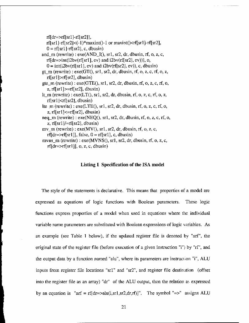
Listing 1 Specification of the ISA model
The style of the statements is declarative. This means that properties of a model are
expressed as equations of logic functions with Boolean parameters. These logic
functions express properties of a model when used in equations where the individual
variable name parameters are substituted with Boolean expressions of logic variables. As
an example (see Table 1 below), if the updated register file is denoted by "nrf", the
original state of the register file (before execution of a given instruction "i") by "rf", and
the output data by a function named "alu", where its parameters are instruct ion "i", ALU
inputs from register file locations "srl" and "sr2", and register file destination (offset
into the register file as an array) "dr" of the ALU output, then the relation as expressed
by an equation is "nrf = rf[dr=>alu(i,srl,sr2,dr,rf)]". The symbol "=>" assigns ALU
21
output at offset "dr" into the register file "rf". The objective of the proof steps yet to
come is to show that the substitutions make the equations true. In substitutions involving
the instruction for addition, the equation above becomes "nrf = rf[dr=>rf[srl]+rf[sr2]]"
because the "alu" function produces as output the sum of the register file values input to
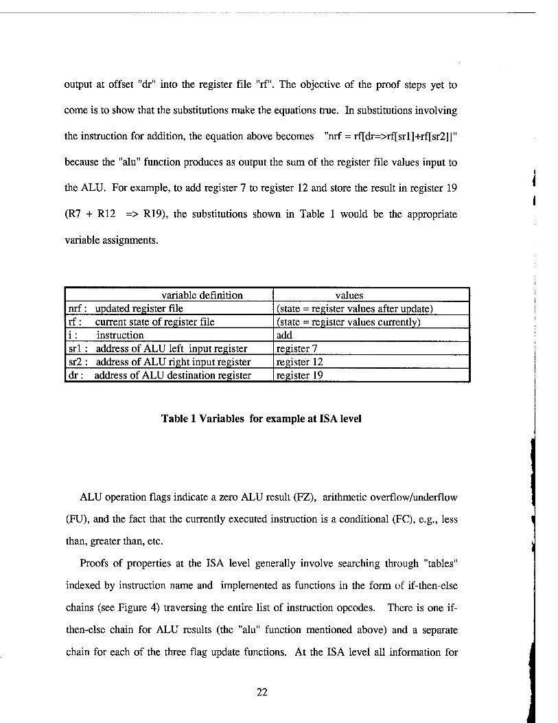
the ALU. For example, to add register 7 to register 12 and store the result in register 19
(R7 + R12 => R19), the substitutions shown in Table 1 would be the appropriate
variable assignments.
variable definition values nrf: updated register file (state = register values after update) rf: current state of register file (state = register values currently) i: instruction add srl : address of ALU left input register register 7 sr2 : address of ALU right input register register 12 dr : address of ALU destination register register 19
Table 1 Variables for example at ISA level
ALU operation flags indicate a zero ALU result (FZ), arithmetic overflow/underflow
(FU), and the fact that the currently executed instruction is a conditional (FC), e.g., less
than, greater than, etc.
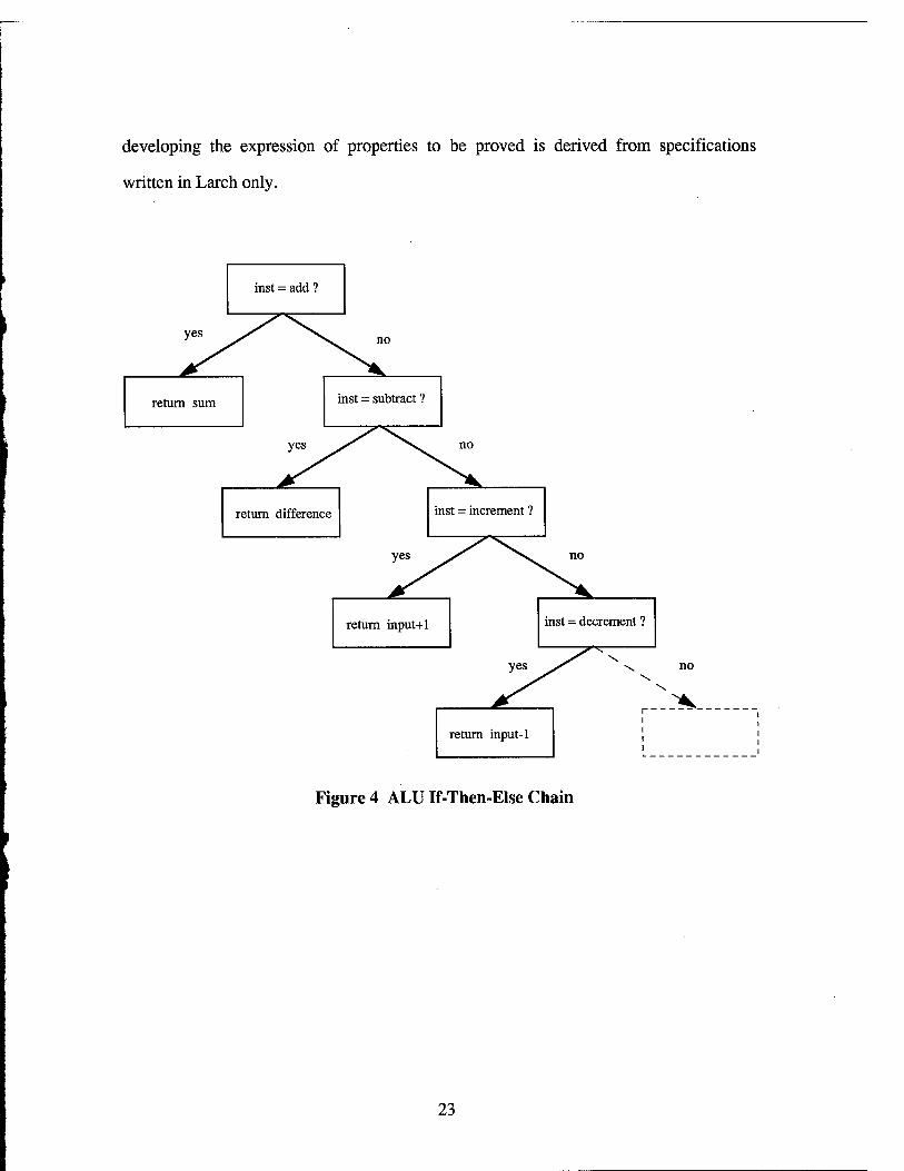
Proofs of properties at the ISA level generally involve searching through "tables"
indexed by instruction name and implemented as functions in the form of if-then-else
chains (see Figure 4) traversing the entire list of instruction opcodes. There is one if-
then-else chain for ALU results (the "alu" function mentioned above) and a separate
chain for each of the three flag update functions. At the ISA level all information for
22
developing the expression of properties to be proved is derived from specifications
written in Larch only.
inst = add ?
return sum inst = subtract ?
return difference inst = increment ?
return input+1 inst = decrement ?
■^
yes \
return input-1
no \
x
Figure 4 ALU If-Then-Else Chain
23
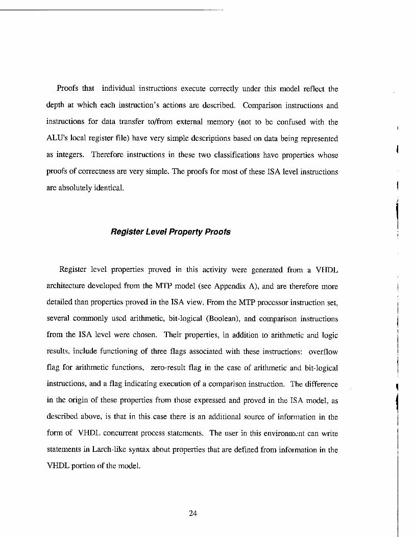
Proofs that individual instructions execute correctly under this model reflect the
depth at which each instruction's actions are described. Comparison instructions and
instructions for data transfer to/from external memory (not to be confused with the
ALU's local register file) have very simple descriptions based on data being represented
as integers. Therefore instructions in these two classifications have properties whose
proofs of correctness are very simple. The proofs for most of these ISA level instructions
are absolutely identical.
Register Level Property Proofs
Register level properties proved in this activity were generated from a VHDL
architecture developed from the MTP model (see Appendix A), and are therefore more
detailed than properties proved in the ISA view. From the MTP processor instruction set,
several commonly used arithmetic, bit-logical (Boolean), and comparison instructions
from the ISA level were chosen. Their properties, in addition to arithmetic and logic
results, include functioning of three flags associated with these instructions: overflow
flag for arithmetic functions, zero-result flag in the case of arithmetic and bit-logical
instructions, and a flag indicating execution of a comparison instruction. The difference
in the origin of these properties from those expressed and proved in the ISA model, as
described above, is that in this case there is an additional source of information in the
form of VHDL concurrent process statements. The user in this environment can write
statements in Larch-like syntax about properties that are defined from information in the
VHDL portion of the model.
24
Construct the Larch traits
Verify the soundness of
the traits
System automatically generatesthe
Verification Conditions
Construct the Larch specification
1 Verify the soundness
of the specification
I Prove correctness ofVHDLdesign
Generate the VHDL model
Annotate the VHDL Entity with "guarantees" logic
statement
Stop
Change the "guarantees" logic statement to check
for a new property
Fix the "guarantees"
Fix the VHDL code
Figure 5 Verifying VHDL Designs
25
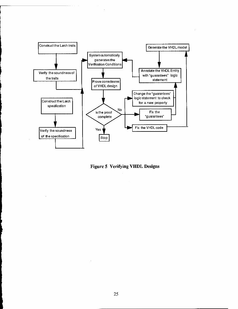
With VHDL, properties to be proved can be expressed more precisely than with
specifications alone. As a related benefit in an environment involving VHDL, more of
the process of deriving properties to be proved (some properties described as verification
conditions, or VC's) can be automated. In contrast to higher level specifications, where
there is a much wider variety of syntax available for describing concepts not necessarily
confined to hardware description, the majority of VHDL syntax supports very regular
and repeatable constructs, such as gates, registers, and interactions among them. User
supplied properties ("the specification") are also referred to as "guarantees". See Figure
5. It is a more detailed version of Figure 2 in that it emphasizes the dynamics of proof
process iteration, as opposed to Figure 2, which featured inputs to this process. Much of
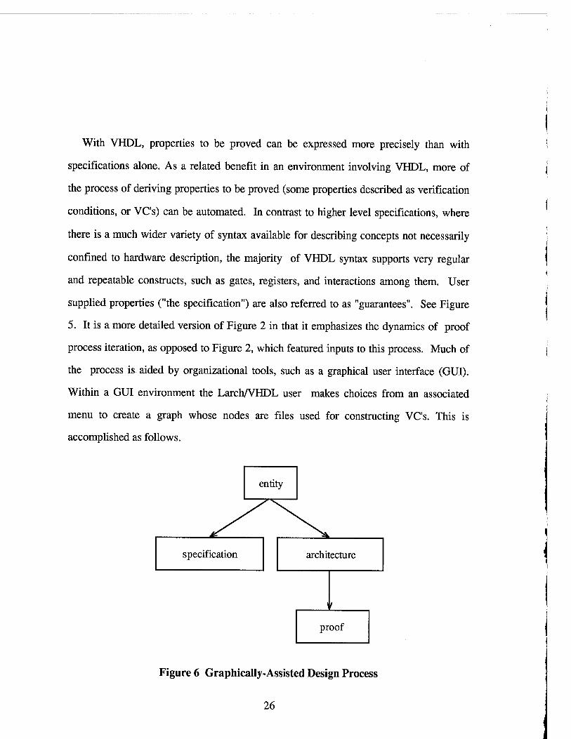
the process is aided by organizational tools, such as a graphical user interface (GUI).
Within a GUI environment the Larch/VHDL user makes choices from an associated
menu to create a graph whose nodes are files used for constructing VC's. This is
accomplished as follows.
entity
specification architecture
proof
Figure 6 Graphically-Assisted Design Process
26
The user supplies file names and directory pathnames for four files: a VHDL entity, a
VHDL architecture, proof node, and a Larch-like specification. The entity node is
constructed first, and the pull-down menu at the already-constructed entity node allows
even more automated construction of the associated specification node, VHDL
architecture node, and proof node. Pull-down menus at the entity node, specification
node, and VHDL architecture node allow an editor (e.g., emacs, vi) to create/open these
files directly from their respective nodes on the graph. The specification contains the
"guarantee", or property, to be proved about the VHDL architecture. See Figure 6 and
Figure 1 above. The pull-down menu at the proof node allows the user to open the
interactive proof editor (Penelope) and automatically construct and load the proof.
Note that depending on how much the user has interacted with the proof process
already, the proof file loaded may be the file representing progress ranging anywhere
from a beginning situation just after the VC's have been generated (no proof steps have
been made yet), to a completed proof. These capabilities require then that the user has
first constructed a VHDL entity file, a specification file, and a VHDL architecture file.
Finally the proof editor is opened and loaded automatically with the VC's and other
properties (the "guarantees") recognizable from the specification file. At this point the
user is ready to start proving the correctness of the VC's by using the proof editor
interactively. Examples of related sets of entities, specifications, and architectures are
given in Appendix E.
Conclusions about Verification at Multiple Levels
The Larch/VHDL tool supports the verification of components at different levels of
the design hierarchy: ISA, behavioral and RTL, and the verification of the composition
27
of previously verified components. Both features simplify the design process and
support the designer's view of the world. The user can reason about the higher level
design aspects entirely within the Larch portion of the environment, and then when
comfortable with the high level, use parts of the Larch specification as "guarantees" to
verify the VHDL design.
User involvement in the proof process extends to more than just the ability to select
proof steps and arrange the order of applying them. The user has the option of reaching
proof completion by applying domain knowledge to decrease the number of proof steps.
This is a more active approach than responding passively to a proof obligation that
remains after applying the most recent proof step. Domain knowledge is applied to the
proof by making a claim which splits the remaining proof obligation into two parts, a
new proof obligation to prove correct the statement of the claim itself with the
hypotheses prior to the claim's existence, and a second part which repeats the original
proof obligation and hypotheses augmented by the claim as a new hypothesis. Therefore,
the claim has to be proved correct, and then it can be used as an additional hypothesis
with the original proof obligation. The syntax of the claim is a statement about logic
variables which appear in the original proof obligation. There is a tradeoff between the
opportunity for shorter proofs and the amount of domain knowledge required of the user
in order to state a claim effective at shortening the proof.
The user also needs to determine optimal substitutions when instantiating theorems
(see section on terminology). The challenge of this requirement is partially lessened by
libraries of specifications for general mathematics (of integers) and libraries of
specifications (theories) implementing VHDL semantics and high level bit vector
constructs. These have been supplied as part of the Larch/VHDL environment. The
theorems from these libraries are extensive, and as would be expected, the bit vector
libraries have been referenced most often during this evaluation. They are built upon the
general mathematics specifications and there was rarely a need either to instantiate
28

theorems directly from general mathematics libraries, or to prove theorems beyond those
already available in the delivered libraries. Most effort was devoted to using the
theorems from these libraries effectively.
Despite the demands on the user's domain knowledge and judgment in setting up a
proof strategy (or borrowing and modifying one), the advantage of having this particular
proof editor as part of the tool environment is the support it provides for putting together
a proof strategy. The libraries of proven theorems about general mathematics, logic, and
special constructs needed for hardware design reasoning, such as bit vectors and their
conversions to integers, relieve the user from extensive work in building a set of
theorems.
Conclusions
Adopting a formal specification and proof of correctness methodology has produced
several benefits over traditional simulation based design environments.
Formulating high level Larch specifications in itself uncovered design omissions and
errors in the early stages of this project, particularly with regard to behavioral definitions
of integer arithmetic. Specific behavioral descriptions related to shifting operations and
arithmetic overflow were clarified when discrepancies were identified in the process of
writing formal specifications from ordinary English descriptions of behavior. The
operative difference is that although one could precede traditional simulation with a
formal specification, the formal specifications used in connection with theorem proving
are linked to the theorem proving activity by the "guarantees" statements referenced
earlier in this report. The specification process, while as thorough as possible for
29
capturing a designer's intentions, when followed by standalone simulation allows another
source of error to be injected via misinterpretation between specification and
simulation.
There are a number of reasons why theorem proving compares favorably with
simulation.
As stated briefly before, proof of each theorem about a design covers correctness of
multiple design input configurations otherwise treated separately under simulation. The
typical argument in favor of theorem proving versus simulation for data paths is that for
any combination of O's and l's on a bus, with the data path width as the exponent and
two as a base, there are two to that exponent possible combinations of data path values.
All of these combinations must be simulated separately in lieu of proving a single
theorem characterizing the setting and reading (interpreting) of the entire bit field
representing those values. Such theorems would generally describe the effect of a
change in one bit of data in this data field on any subdesign which uses the data path as
input. Beyond this initial concern over combinatorial explosion (complexity exponential
in the data path width), the data path paradigm is treated much more generally by
theorem proving, as many proof environments allow the user to parameterize all
theorems and proofs on the width of the data path without specifying width explicitly.
Alternatively, a change in data path width requires that a simulation based check for
correctness would have to be repeated from the beginning.
The repetitious nature of simulation makes human interaction less effective
(monotony and propensity for errors in human review of massive displays of very similar
patterns) and makes no use of the hierarchy of design possible with theorem proving.
Although no claim is made that portions of that hierarchy handled best by theorem
proving techniques are a total replacement for simulation, the structure of such a
30
hierarchy is made more apparent to the user of a theorem proving environment. Subtle
design flaws masked by poorly chosen hierarchical structure would be harder to detect
with simulation. A secondary benefit of obvious theorem prover support for hierarchy in
design is that the entire design can be more easily comprehended. Since hierarchy also
ensures more modularity, parts of a given design can be more easily isolated within a
theorem proving environment, for later reuse in another design. In contrast, although a
simulation environment allows separating parts of design for independent simulation, the
combinatorial explosion problem referenced earlier is made worse when data paths are
disconnected to isolate modules in a more detailed phase of a design. The number of
input and output port data paths (at the boundaries of the newly created modules) is
increased, thereby increasing at least linearly the total number of unique input and
output combinations to be verified. The number of input and output combinations to be
checked doubles for every disconnection.
Bibliography
[1] Edsger W. Dijkstra, A Discipline of Programming. Prentice Hall, Englewood Cliffs, 1976.
[2] S. Garland, J. Guttag and J. Horning, "Debugging Larch Shared Language Specification," IEEE Trans, on Software Engineering, Vol. 16, no. 9, September 1990.
[3] David Gries, The Science of Programming. Springer-Verlag, 1981.
[4] J. Guttag, J. Horning and J. Wing, "The Larch Family of Specification Languages," IEEE Software, September 1985.
[5] J. Jamsek and M. Bickford, "Formal Verification of VHDL Models," Final Technical Report, Rome Laboratory RL-TR-94-3, March, 1994.
31
[6] J. Wing, "Writing Larch Interface Language Specifications," ACM Trans, on Programming Languages and Systems, Vol. 9, no. 1, January, 1987.
[7] Odyssey Research Associates, "Penelope Reference Manual V3-3," TM94-0009, December, 1993.
[8] M.Nassif and R. Paragi, "The Larch/VHDL Methodology for Hardware Verification", 1996
[9] M. Bickford, "User/Training Manual for Formal Verification of VHDL Design", TM-96-0024, July, 1996
[10] M. Bickford, "Final Report for Formal Verification of VHDL Design", TM-96- 0025, July, 1996
[11]] E. Stabler, M. Nassif and R. Paragi, "Extending the Design Process with Formal Verification Technology", The Spring 1996 VHDL International Users' Forum Conference, February, 1996
[12] A. Barbour, "Formal Hardware Verification Using The Larch/VHDL Theorem Prover", Final Report for Summer Faculty Research Program, August, 1996
[13] E. Stabler, M. Nassif and R. Paragi, "Verification of ASIC Designs in VHDL Using Computer-Aided Reasoning", ASIC Conference, September, 1996
[14] Z. Navabi, VHDL: Analysis and Modeling of Digital Systems, McGraw-Hill, 1993
[15] G. Nelson and D. Oppen," Simplification by Cooperating Decision Procedures", ACM Transactions on Programming Languages and Systems, Vol. 1, No. 2, October, 1979
[16] S-K Chin, "Formal Specification and Verification of the Am2910 Sequencer", CASE Center Technical Report No. 9401, January, 1994.
32
Appendix A: Multiple Technology Processor (MTP)
ALU VHDL Description
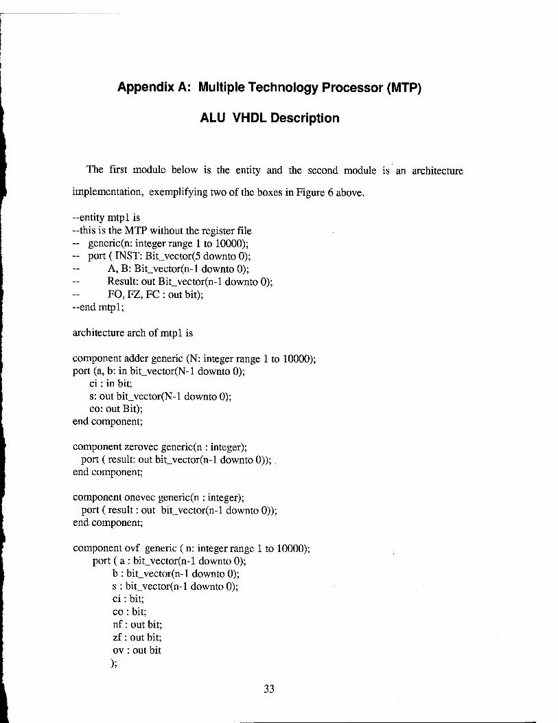
The first module below is the entity and the second module is an architecture
implementation, exemplifying two of the boxes in Figure 6 above.
--entity mtpl is -this is the MTP without the register file - generic(n: integer range 1 to 10000); - port (INST: Bit_vector(5 downto 0);
A, B: Bit_vector(n-l downto 0); Result: out Bit_vector(n-l downto 0); FO, FZ, FC : out bit);
-end mtpl;
architecture arch of mtpl is
component adder generic (N: integer range 1 to 10000); port (a, b: in bit_vector(N-l downto 0);
ci: in bit; s: out bit_vector(N-l downto 0); co: out Bit);
end component;
component zerovec generic(n : integer); port (result: out bit_vector(n-l downto 0));.
end component;
component onevec generic(n : integer); port (result: out bit_vector(n-l downto 0));
end component;
component ovf generic ( n: integer range 1 to 10000); port ( a : bit_vector(n-1 downto 0);
b : bit_vector(n-l downto 0); s : bit_vector(n-l downto 0); ci: bit; co: bit; nf: out bit; zf: out bit; ov: out bit );
33
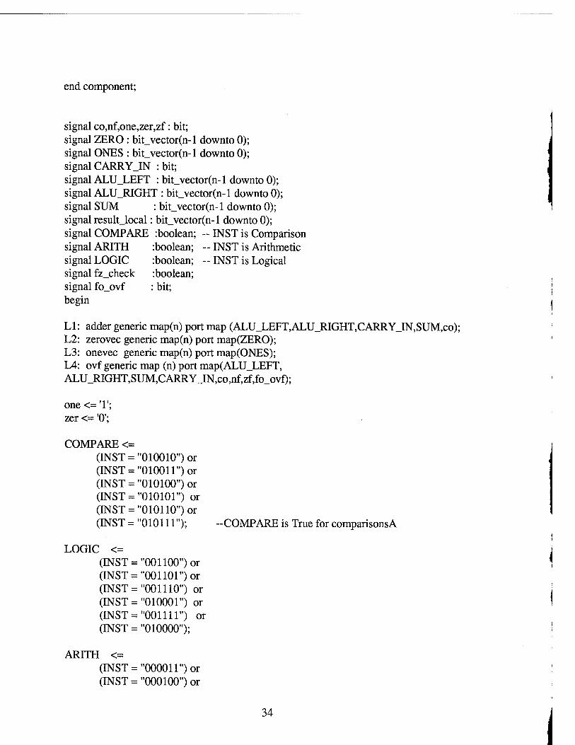
end component;
signal co,nf,one,zer,zf: bit; signal ZERO : bit_vector(n-l downto 0); signal ONES : bit_vector(n-l downto 0); signal CARRYJN : bit; signal ALU_LEFT : bit_vector(n-l downto 0); signal ALU_RIGHT : bit_vector(n-l downto 0); signal SUM : bit_vector(n-l downto 0); signal resultjocal: bit_vector(n-1 downto 0); signal COMPARE :boolean; -- INST is Comparison signal ARITH :boolean; -- INST is Arithmetic signal LOGIC :boolean; --INST is Logical signal fz_check :boolean; signal fo_ovf : bit; begin
LI: adder generic map(n) port map (ALU_LEFT,ALU_RIGHT,CARRY_IN,SUM,co); L2: zerovec generic map(n) port map(ZERO); L3: onevec generic map(n) port map(ONES); L4: ovf generic map (n) port map(ALUJLEFT, ALU_RIGHT,SUM,CARRY_IN,co,nf,zf,fo_ovf);
one <= T; zer <= '0';
COMPARE <= (INST = "010010") or (INST = "010011") or (INST = "010100") or (INST = "010101") or (INST = "010110") or (INST = "010111"); -COMPARE is True for comparisonsA
LOGIC <= (INST = "001100") or (INST ="001101") or (INST ="001110") or (INST ="010001") or (INST ="001111") or (INST = "010000");
ARITH <= (INST = "000011") or (INST = "000100") or
34
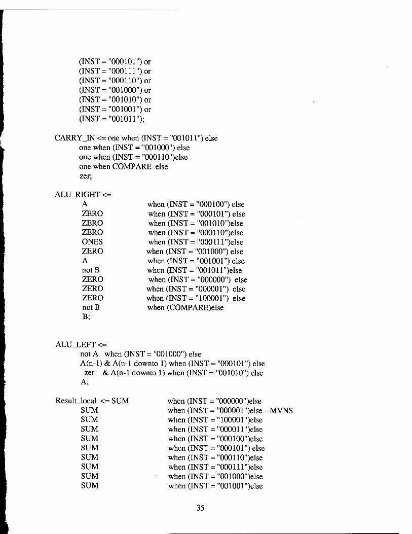
(INST = "000101") or (INST = "000111") or (INST ="000110") or (INST = "001000") or (INST = "001010") or (INST ="001001") or (INST = "001011");
CARRYJN <= one when (INST = "001011") else one when (INST = "001000") else one when (INST = "000110")else one when COMPARE else zer;
ALU_RIGHT <= A when (INST = "000100") else ZERO when (INST = "000101") else ZERO when (INST = "001010")else ZERO when (INST = "000110")else ONES when (INST = "000111 ")else ZERO when (INST = "001000") else A when (INST = "001001") else not B when (INST = "001011 ")else ZERO when (INST = "000000") else ZERO when (INST = "000001") else ZERO when (INST = "100001") else not B when (COMPARE)else B;
ALU_LEFT <= not A when (INST = "001000") else A(n-l) & A(n-1 downto 1) when (INST = "000101") else
zer & A(n-1 downto 1) when (INST = "001010") else A;
Resultjocal <= SUM when (INST = "000000")else SUM when (INST = "000001")else --MVNS SUM when (INST = "100001")else SUM when (INST = "00001 l")else SUM when (INST = "000100")else SUM when (INST = "000101") else SUM when (INST = "000110")else SUM when (INST = "000111 ")else SUM when (INST = "001000")else SUM when (INST = "001001 ")else
35
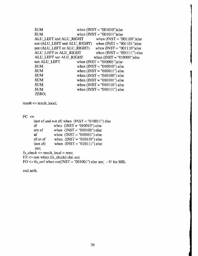
SUM SUM
when (INST = "001010")else when (INST = "00101 l")else
ALUJJEFT and ALU_RIGHT not (ALU_LEFT and ALU_RIGHT) not (ALU_LEFT or ALU_RIGHT) ALU_LEFT or ALU_RIGHT ALU_LEFT xor ALU_RIGHT not ALUJJEFT SUM SUM SUM SUM SUM SUM ZERO;
when (INST = "001100")else when (INST = "001101 ")else when (INST = "001110")else when (INST = "001111") else
when (INST = "010000")else when (INST = "010001 ")else when (INST = "010010") else when (INST = "010011") else when (INST = "010100") else when (INST = "010101") else when (INST = "010110") else when (INST = "010111") else
result <= result local;
FC <= (not nf and not zf) when (INST = "010011") else
when (INST = "010010") else when (INST = "010100") else when (INST = "010101") else when (INST = "010110") else when (INST = "010111") else
zf notnf nf nf or zf (not zf) zer;
fz_check <= result_local = zero; FZ <= one when (fz_check) else zer; FO <= fo_ovf when not(INST = "001001") else zer; -'0' for SHL
end arch;
36
Appendix B: Multiple Technology Processor (MTP) Specification
This is the Instruction Set Architecture (ISA) view of the MTP. (See Table 2 below.)
It summarizes the functional descriptions given in the MTP specification at the assembly
language level of behavior. The mnemonic names for the usual arithmetic and logic
(ALU) instructions and the data transfer instructions (MV, MVNS, STO, and LD) are
given in the first column. (MV and MVNS allow the movement of data through the
ALU without modifying it. MVNS disables flag setting on the operation. STO and LD
allow data movement between the register file associated with the ALU and off-chip
memory.) The third and fourth columns list the range of registers which may be used as
data sources for the ALU. The range of registers allowed for storing the result generated
by the ALU is shown in the fifth column.
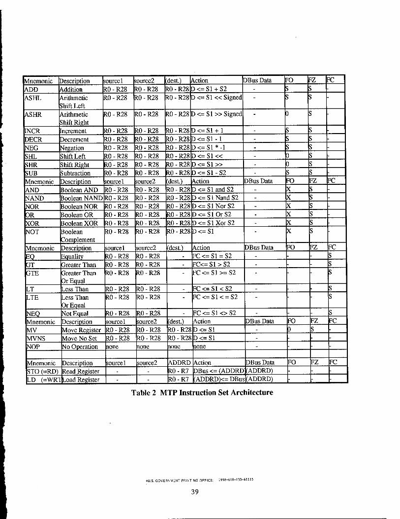
The sixth column shows the effect of each instruction. SI and S2 are the two
inputs to the ALU. D represents the register file offset destination of the ALU output
port, and Dbus represents a bus connecting register file and off-chip memory. ADDRD
is the destination address specified for the ALU output. FC is a flag set by execution of
conditional instructions, a distinction to detect branching. The only effect of conditional
instructions is to set this flag. Shift instructions use the double angle-bracket ("«" or
"»") to denote shifting in the indicated direction. Note that arithmetic shift instructions
are further annotated to indicate sign replication in the higher order bits on a shift right
(toward lower order bit positions).
The seventh column emphasizes that only the STO and LD instructions use the D
Bus.
37
The last three columns' subjects are three flags: FO, FZ, and FC. FO is set by
arithmetic overflow, and FZ is set by an ALU result of zero. Within these last three
columns' entries, S indicates that the flag can be modified by execution of the
instruction, X indicates that the flag can be set but is not used ("don't care" condition),
"-" indicates that the flag cannot be changed by execution of the given instruction, and
"0" indicates the known setting.
38
I
Mnemonic ADD ASHL
INCR
Description source 1 Addition Arithmetic Shift Left
ASHR Arithmetic Shift Right Increment
DECR NEG
RO - R28 RO - R28
RO - R28
RO - R28 Decrement Negation
source2 RO - R28 R0-R28
RO - R28
R0-R28 RO - R28
(dest.) RO - R28 RO - R28
RO - R28 D <= SI » Signed
RO - R28 RO - R28 RO - R28
Action D<=S1 + S2 D<= SI «Signed
RO - R28 RO - R28
DBus Data FO
RO - R28 D <= SI + 1 D<=S1-1 D<=S1*-1
D
FZ FC
SHL Shift Left RO - R28 RO - R28 R0-R28D<=S1« 0 SHR Shift Right RO - R28 RO - R28 R0-R28D<=S1» 0 SUB Subtraction R0-R28 R0-R28 RO-R28 D<= SI - S2 Mnemonic Description sourcel source2 (dest.) Action DBus Data FO FZ FC
AND Boolean AND RO - R28 RO - R28 RO - R28 D<=SlandS2 X NAND NOR
Boolean NAND RO - R28 RO - R28 R0-R28D<=SlNandS2 X Boolean NOR RO - R28 RO - R28 R0-R28D<=SlNorS2
OR Boolean OR RO - R28 RO - R28 RO-R28D<=S10rS2 X
XOR Boolean XOR RO - R28 RO - R28 R0-R28D<=SlXorS2 X NOT Boolean
Complement R0-R28 RO - R28 RO - R28 D<=S1
Mnemonic Description sourcel source2 (dest.) Action DBus Data FO FZ FC
EQ_ Equality RO - R28 RO - R28 FC<=S1 = S2 GT Greater Than RO - R28 R0-R28 FC<=S1>S2 GTE Greater Than
Or Equal RO - R28 RO - R28 FC<=S1>=S2
LT Less Than RO - R28 RO - R28 LTE Less Than
Or Equal RO - R28 RO - R28
FC<=S1<S2 FC<=S1< = S2
NEQ Not Equal RO - R28 RO - R28 FC <= SI <> S2 Mnemonic Description sourcel source2 (dest.) Action DBus Data FO FZ FC
MV Move Register RO - R28 RO - R28 RO - R28 D<=S1 MVNS Move No Set R0-R28 RO - R28 RO - R28 D<=S1 NOP No Operation none none none none
Mnemonic Description sourcel source2 ADDRD Action DBus Data FO FZ FC
STO (=RD) Read Register R0-R7 DBus <= (ADDRD (ADDRD) LD (=WRT^oad Register RO - R7 (ADDRD)<= DBus (ADDRD)
Table 2 MTP Instruction Set Architecture
«U.S. GOVERNMENT PRINTING OFFICE: 1998-610-130-61115
39

MISSION OF
ROME LABORATORY
Mission. The mission of Rome Laboratory is to advance the science and technologies of command, control, communications and intelligence and to transition them into systems to meet customer needs. To achieve this, Rome Lab:
a. Conducts vigorous research, development and test programs in all applicable technologies;
b. Transitions technology to current and future systems to improve operational capability, readiness, and supportability;
c. Provides a full range of technical support to Air Force Material Command product centers and other Air Force organizations;
d. Promotes transfer of technology to the private sector;
e. Maintains leading edge technological expertise in the areas of surveillance, communications, command and control, intelligence, reliability science, electro-magnetic technology, photonics, signal processing, and computational science.
The thrust areas of technical competence include: Surveillance, Communications, Command and Control, Intelligence, Signal Processing, Computer Science and Technology, Electromagnetic Technology, Photonics and Reliability Sciences.