everpex™ installation guide
TRANSCRIPT

IEVERPEX™ INSTALLATION GUIDE
Building essentials for a better tomorrow
INSTALLATION GUIDE
EVERPEX™

II EVERPEX™ INSTALLATION GUIDE

1EVERPEX™ INSTALLATION GUIDE
INTRODUCTION TO EVERPEX - PLUMBING SySTEM . . . . . . . . . . . . . . . 6
EVERPEX™ CERTIfICATIONS, LISTINGS AND
MANUfACTURER STANDARDS . . . . . . . . . . . . . . . . . . . . . . . . . . . . . . . . 7
STORAGE AND HANDLING . . . . . . . . . . . . . . . . . . . . . . . . . . . . . . . . . . . 7
INSTALLATION GUIDELINES . . . . . . . . . . . . . . . . . . . . . . . . . . . . . . . . . . . 8
PROTECTING EVERPEX™ TUBING . . . . . . . . . . . . . . . . . . . . . . . . . . . . . 12
EVERPEX™ THERMAL EXPANSION RATE . . . . . . . . . . . . . . . . . . . . . . . . 12
BENDING RADIUS . . . . . . . . . . . . . . . . . . . . . . . . . . . . . . . . . . . . . . . . . . 13
HANGERS AND SUPPORTS . . . . . . . . . . . . . . . . . . . . . . . . . . . . . . . . . . 13
RECESSED LIGHTING MINIMUM SEPARATIONS . . . . . . . . . . . . . . . . . . 14
HOT WATER HEATER REQUIREMENTS . . . . . . . . . . . . . . . . . . . . . . . . . 14
EVERPEX™ JOINTS AND CONNECTIONS . . . . . . . . . . . . . . . . . . . . . . . . 15
MANIfOLD LOCATION AND ROUGH IN REQUIREMENTS . . . . . . . . . . . 16
INSPECTION AND TESTING . . . . . . . . . . . . . . . . . . . . . . . . . . . . . . . . . . 17
ELECTRICAL GROUNDING . . . . . . . . . . . . . . . . . . . . . . . . . . . . . . . . . . . 17
THAWING fROZEN TUBING . . . . . . . . . . . . . . . . . . . . . . . . . . . . . . . . . . 17
fIRE STOP . . . . . . . . . . . . . . . . . . . . . . . . . . . . . . . . . . . . . . . . . . . . . . . 18
WATER HAMMER IN THE EVERPEX™ SUPPLIED SySTEM . . . . . . . . . . 18
CONCRETE SLAB INSTALLATIONS . . . . . . . . . . . . . . . . . . . . . . . . . . . . 18
SySTEM SANITIZATION . . . . . . . . . . . . . . . . . . . . . . . . . . . . . . . . . . . . . 19
BURIAL INSTRUCTIONS fOR BRASS INSERT fITTINGS . . . . . . . . . . . . 19
HOME-RUN MANIfOLD SySTEMS . . . . . . . . . . . . . . . . . . . . . . . . . . . . 20
SUBMANIfOLD SySTEMS . . . . . . . . . . . . . . . . . . . . . . . . . . . . . . . . . . 21
01
02
03
04
05
06
07
08
09
10
11
12
13
14
15
16
17
18
19
20
21
22
CONTENTS
EVERPEX™

2 EVERPEX™ INSTALLATION GUIDE
Limited Warranty
J-M Manufacturing Company, Inc. (JM Eagle™) warrants that its EverPEX™ (cross-linked Polyethylene) tubing and related products (“Products”) are manufactured in accordance with applicable industry specifications refer-enced on the Product and are free from defects in workmanship and ma-terials. Every claim under this warranty shall be void unless in writing and received by JM Eagle™ within thirty (30) days of the date the defect was discovered, and according to the following:
PROfESSIONALLy INSTALLED PRODUCTS
• EverPEX™ tubing: within twenty-five (25) years of the date of documented installation when properly installed by a licensed profes-sional installer;
• EverPEX™ system supplied fittings and manifolds: within ten (10) years of the date of documented installation when properly in-stalled by a licensed professional installer;
• EverPEX™ electrical and other approved applications: within two (2) years of the date of documented installation when properly installed by a licensed professional installer.
• Non-Professionally Installed Products (It is highly recom-mended that the Product be professionally installed)
• IN ALL INSTANCES WHERE THE PRODUCT IS INSTALLED BY A NON-LICENSED INSTALLER THIS LIMITED WARRANTY SHALL, FOR ANY PRODUCT AND IN ALL APPLICATIONS, IS LIMITED TO ONE (1) YEAR FROM THE DATE OF PURCHASE.
This warranty specifically excludes any Products allowed to become sun-bleached after shipment from the JM Eagle™ plant and is void if the Product is not stored away from direct sun-light.

3EVERPEX™ INSTALLATION GUIDE
Proof of purchase with the date thereof and a copy of the installer’s profes-sional license must be presented to the satisfaction of JM Eagle™, with any claim made pursuant to this warranty. JM Eagle™ must first be given an op-portunity to inspect the alleged defective Products in order to determine if they meet applicable industry standards, if the handling and installation have been satisfactorily performed in accordance with JM Eagle™ recommended practices and if operating conditions are within standards. Written permis-sion and/or a Return Goods Authorization (RGA) must be obtained along with instructions for return shipment to JM Eagle™ of any Products claimed to be defective.
The limited and exclusive remedy for breach of this Limited Warranty shall be, at JM Eagle’s sole discretion, the replacement of the same type, size and like quantity of non-defective Product, or credits, offsets, or combination of thereof, for the wholesale purchase price of the defective unit.
This Limited Warranty is void for any installations not conforming with indus-try standards and JM Eagle’s installation guidelines and/or Product failures caused by user’s flawed designs or specifications, unsatisfactory applica-tions, improper installations, use in conjunction with incompatible materials, contact with aggressive chemical agents, direct sunlight, freezing or over-heating of liquids in the Product and any other misuse causes not listed here. This Limited Warranty also excludes failure or damage caused by force majeure-type incidents (including, but not limited to, acts of nature, floods, hurricanes, and terrorist acts) or damage caused by the fault or negligence of anyone other than JM Eagle™, or any other act or event beyond the control of JM Eagle™.
JM Eagle’s liability shall not, at any time, exceed the actual wholesale pur-chase price of the Product. The warranties in this document are the only warranties applicable to the Product and there are no other warranties, ex-pressed or implied. This Limited Warranty specifically excludes any liability for general damages, consequential or incidental damages, including with-out limitation, costs incurred from removal, reinstallation, or other expenses resulting from any defect.

4 EVERPEX™ INSTALLATION GUIDE
JM Eagle’s Products should be used in accordance with standards set forth by local plumbing and building laws, codes, or regulations and applicable standards. failure to adhere to these standards shall void this Limited War-ranty. Products sold by JM Eagle™ that are manufactured by others are warranted only to the extent and limits of the warranty of the manufacturer. No statement, conduct or description by JM Eagle™ or its representative, in addition to or beyond this Limited Warranty, shall constitute a warranty. This Limited Warranty may only be modified in writing signed by an officer of JM Eagle™.
IMPLIED WARRANTIES Of MERCHANTABILITy OR fITNESS fOR A PAR-TICULAR PURPOSE ARE SPECIfICALLy DISCLAIMED NOTWITHSTAND-ING JM EAGLE’S ACTUAL KNOWLEDGE Of THE PRODUCT’S INTENDED USE. Some states do not allow limitations on implied warranties ON GOODS SOLD DIRECTLy TO CONSUMERS, so the above limitation may not apply IN ALL CASES.

5EVERPEX™ INSTALLATION GUIDE
1. introduction to everPeX™ — PLumbing SyStem
J-M Manufacturing Company (JM Eagle™) is introducing the EverPEX™ plumbing system. EverPEX™ (cross-linked Polyethylene) tubing is an excel-lent alternative to traditional plumbing materials. The molecules in EverPEX™ are modified to cause the molecules to link together permanently. Once High Density Polyethylene (HDPE) is cross-linked it becomes a thermo-set plastic, meaning it cannot be melted and reshaped. Plumbing suppliers, contractors and builders can rest assured that JM Eagle™, the industry leader in plastic pipe, will stand behind EverPEX’s tubing and fitting availability and their war-ranties for years to come.
EverPEX™ is a PEX – product produced by the silane moisture cure method. Most cross-linking takes place after the material has left the extruder. The cross-linking is achieved by introducing moisture and temperature through exposure to hot water or steam.
EverPEX™ has many useful potable water applications in residential, com-mercial and industrial construction. EverPEX™ has a high temperature capa-bility, and is pressure rated up to 80 psi at 200° f. Because of its smooth wall, EverPEX™ has excellent flow characteristics. Additionally, it has increased flexibility for easy design and installation and is corrosion-resistant. In addi-tion to hot and cold potable water plumbing applications, EverPEX™ can be used for hydronic radiant heating, snow and ice melting applications, solar and swimming pool heating, agricultural and turf applications, even ice rinks and refrigeration warehouses.
This guide will provide plumbing suppliers, as well as tradesmen, installers and inspectors with proper handling, installation and testing requirements for JM Eagle’s EverPEX™ tubing systems.
The use of EverPEX™ for purposes other than those approved by JM Eagle™ is considered a misapplication of the product and voids the EverPEX™ Limited Warranty.
6 EVERPEX™ INSTALLATION GUIDE
2. everPeX™ certificationS, LiStingS and manufacturer StandardS
NSf NATIONAL SANITATION fOUNDATION
• EverPEX™ tubing and supplied fittings are NSf certified to NSf stan-dards 14 and 61.
• PW potable water certificate. NSf-PW• NSf Cl-TD
cNSf (CSA B137.0/137.5)
PLASTIC PIPE INSTITUTE—PRESSURE RATINGS AND TEMPERATURE• High Temperature TR-4 Standards• EverPEX™ tubing systems are rated for 160 psi at 73° f, 100 psi at
180° f. and 80 psi at 200° f.
ASTM• EverPEX™ tubing f876, f877• fittings f1807
U.P. CODE
3. Storage and HandLing
Tubing that is discolored or has been exposed to chemicals, grease, tar or solvents should NOT be used. When cleaning the EverPEX™ tubing, use only a damp water cloth. Discolored, stained or contaminated tubing should be discarded and NOT used.
1. EverPEX™ tubing should be kept out of direct sunlight, ultra violet light can degrade the pipe.
2. EverPEX™ tubing should be stored away from heat sources.3. DO NOT allow petroleum oil or solvent-based paints to contact
EverPEX™.4. DO NOT allow strong acids, pesticides, organic chemicals or strong
bases to come in contact with the EverPEX™ tubing.
7EVERPEX™ INSTALLATION GUIDE
5. EverPEX™ tubing should be stored indoors or inside a cardboard box to keep coils and lengths of tubing clean.
6. DO NOT allow rodents, insects, or other pests to come in contact with tubing.
7. DO NOT use glue, cements weld or use adhesives or tape on EverPEX™ tubing.
8. DO NOT apply an open flame to EverPEX™ tubing.
4. inStaLLation guideLineS
EverPEX™ tubing is color coded to prevent cross connection of hot and cold water lines. EverPEX™ pipe or tubing coils are lightweight and easily uncoiled and shaped by hand for easy rough in through wood frames as well as steel studs in floors, walls or ceilings.
fLARED INSERT fITTINGS
flared insert fittings are manufactured to ASTM f1807 standards and meet all requirements of NSf Standard 14/61, or the listing requirements of IAPMO (uniform plumbing code).
Installers of EverPEX™ supplied fittings should adhere to the guidelines given in this manual pertaining to the use and installation of EverPEX™ tubing with flared fittings and in accordance with accepted plumbing practices. Where fittings are identified as having been manufactured by a third party, the third party’s installation instructions should also be consulted.
flared fittings are designed for use with EverPEX™ tubing manufactured to ASTM f876-/877 standards.
flared fittings are designed to equal or exceed the maximum pressure and temperature ratings of EverPEX™ tubing; 160 psi at 73° f, 100 psi at 180° f and 80 psi at 200° f.

8 EVERPEX™ INSTALLATION GUIDE
PROCEDURE fOR INSTALLING fLARED fITTINGS:
1. Cut tubing squarely, slide nut over tubing.2. Rock tubing onto flared cone until it rests against the shoulder of
the fitting.3. Slide nut to the threads and tighten securely. These threads require
no glue, pipe dope, or Teflon® tape.
HIGH TEMPERATURE PLASTIC MANIfOLD
The manifold should be secured to an interior wall, in close proximity to the hot water heater to maximize efficiency. (The manifold should never touch the water heater or any other sources of heat.)
PROCEDURE fOR INSTALLING MANIfOLD:
1. All tubing ends are to be cut squarely and free of any burrs.2. Slide nut over tubing.3. firmly rock tubing onto flare cone of the fitting until it rests against the
shoulder of the fitting.4. Slide the nut to the threads and tighten securely onto fitting or valve.5. Tighten swivel nut onto outlet port of manifold.
These connections do not require Teflon® tape or pipe dope. When connect-ing male pipe threads to female pipe threads, use only Teflon® tape.
If installing a brass ballcock valve, you need to cut the end of the tubing squarely and free of any burrs.
PROCEDURE fOR INSTALLING A BRASS BALLCOCK VALVE:
1. Slide crimp ring or clamp over tubing end. 2. Crimp tubing to the insert end of the valve.3. Tighten swivel nut onto outlet port of manifold.
9EVERPEX™ INSTALLATION GUIDE
RATCHET TOOL CLAMPING INSTRUCTIONS
The ratchet tool clamp system secures EverPEX™ tubing to brass or plas-tic insert fittings using a stainless steel clamp manufactured to ASTM f2098 specifications.
The EverPEX™ tubing’s elastic memory, combined with the clamps spring action, results in an ever-tightening leak-free connection. This connection will withstand specified temperature and pressure changes.
The ratchet tool clamp system has the ability of one tool to crimp all sizes.
PROCEDURE fOR MAKING A GOOD CONNECTION USING BRASS INSERT fITTINGS:
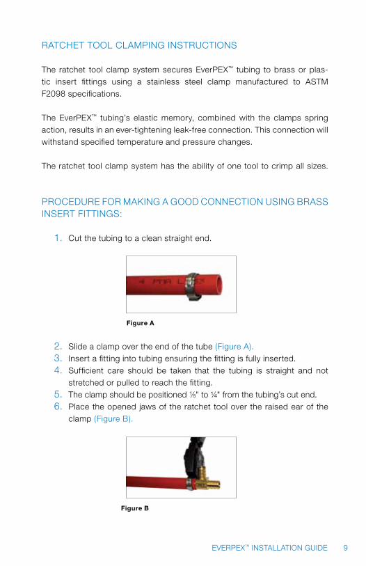
1. Cut the tubing to a clean straight end.
Figure A
2. Slide a clamp over the end of the tube (figure A).3. Insert a fitting into tubing ensuring the fitting is fully inserted.4. Sufficient care should be taken that the tubing is straight and not
stretched or pulled to reach the fitting.5. The clamp should be positioned 1/8" to ¼" from the tubing’s cut end.6. Place the opened jaws of the ratchet tool over the raised ear of the
clamp (figure B).
Figure B
10 EVERPEX™ INSTALLATION GUIDE
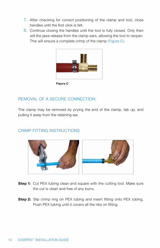
7. After checking for correct positioning of the clamp and tool, close handles until the first click is felt.
8. Continue closing the handles until the tool is fully closed. Only then will the jaws release from the clamp ears, allowing the tool to reopen. This will ensure a complete crimp of the clamp (figure C).
Figure C
REMOVAL Of A SECURE CONNECTION: The clamp may be removed by prying the end of the clamp, tab up, and pulling it away from the retaining ear.
CRIMP fITTING INSTRUCTIONS
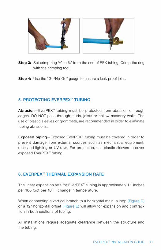
Step 1: Cut PEX tubing clean and square with the cutting tool. Make sure
the cut is clean and free of any burrs.
Step 2: Slip crimp ring on PEX tubing and insert fitting onto PEX tubing. Push PEX tubing until it covers all the ribs on fitting.
11EVERPEX™ INSTALLATION GUIDE
Step 3: Set crimp ring 1/8" to ¼" from the end of PEX tubing. Crimp the ring with the crimping tool.
Step 4: Use the “Go/No-Go” gauge to ensure a leak-proof joint.
5. Protecting everPeX™ tubing
abrasion—EverPEX™ tubing must be protected from abrasion or rough edges. DO NOT pass through studs, joists or hollow masonry walls. The use of plastic sleeves or grommets, are recommended in order to eliminate tubing abrasions.
exposed piping—Exposed EverPEX™ tubing must be covered in order to prevent damage from external sources such as mechanical equipment, recessed lighting or UV rays. for protection, use plastic sleeves to cover exposed EverPEX™ tubing.
6. everPeX™ tHermaL eXPanSion rate
The linear expansion rate for EverPEX™ tubing is approximately 1.1 inches per 100 foot per 10° f change in temperature.
When connecting a vertical branch to a horizontal main, a loop (figure D) or a 12" horizontal offset (figure E) will allow for expansion and contrac-tion in both sections of tubing.
All installations require adequate clearance between the structure and the tubing.

12 EVERPEX™ INSTALLATION GUIDE
Figure D Figure E
7. bending radiuS
EverPEX™ tubing may be shaped by hand. The minimum radius is not to be less than six (6) times the nominal tubing diameter. External bend sup-ports or sleeves may be used to ensure protection of the tubing. failure to keep bend radius six times the nominal tubing diameter voids the EverPEX™ Limited Warranty.
8. HangerS and SuPPortS
EverPEX™ tubing should not be rigidly anchored. EverPEX™ tubing must float on all hangers and straps to allow for movement during expansion and contraction. Proper care should be taken to ensure the EverPEX™ tubing is not pinched or in contact with abrasive or sharp edges. Horizontal tubing runs should be supported every 32 inches (figure f). Always allow slack for expansion and contraction (7" for every 50-foot of run will be sufficient). Use only hangers designed for plastic pipe. Vertical tubing runs should be supported every 48 inches.
32”
Figure F

13EVERPEX™ INSTALLATION GUIDE
HOSE BIBS
Tubing connected directly to any hose bib must be anchored so any load on the hose bib will not put strain on the EverPEX™ tubing.
STUB OUTS
EverPEX™ tubing may be stubbed directly out of a wall. Support brackets may be used so long as they do not deform or kink the EverPEX™ tubing.
9. receSSed LigHting minimum SeParationS
Whenever a UV light or other high temperature emitting source is used, in-sulation is required to protect EverPEX™ tubing. DO NOT install EverPEX™ tubing near recessed lighting fixtures. Where applicable building codes do not exist, a minimum of 12" is required between recessed lights and EverPEX™ tubing. If this is not possible, appropriate insulation rated to withstand the temperature generated by the fixture is required.
10. Hot Water Heater requirementS
WARNING: NEVER connect EverPEX™ tubing directly to a water heater. A minimum of 18" of metallic piping is required between the water heater and the EverPEX™ tubing (figure G).
18”
Figure G
14 EVERPEX™ INSTALLATION GUIDE
11. everPeX™ JointS and connectionS
A. Crimping with copper crimp rings. B. Clamping with stainless steel clamps.
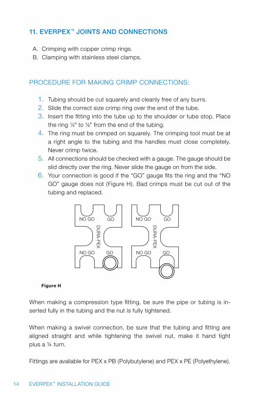
PROCEDURE fOR MAKING CRIMP CONNECTIONS:
1. Tubing should be cut squarely and cleanly free of any burrs.2. Slide the correct size crimp ring over the end of the tube.3. Insert the fitting into the tube up to the shoulder or tube stop. Place
the ring 1/8" to ¼" from the end of the tubing.4. The ring must be crimped on squarely. The crimping tool must be at
a right angle to the tubing and the handles must close completely. Never crimp twice.
5. All connections should be checked with a gauge. The gauge should be slid directly over the ring. Never slide the gauge on from the side.
6. your connection is good if the “GO” gauge fits the ring and the “NO GO” gauge does not (figure H). Bad crimps must be cut out of the tubing and replaced.
NO GO
NO GO GO
GO
DU
RA
-PE
X
NO GO
NO GO GO
GO
DU
RA
-PE
X
Figure H
When making a compression type fitting, be sure the pipe or tubing is in-serted fully in the tubing and the nut is fully tightened.
When making a swivel connection, be sure that the tubing and fitting are aligned straight and while tightening the swivel nut, make it hand tight plus a ¼ turn.
fittings are available for PEX x PB (Polybutylene) and PEX x PE (Polyethylene).
15EVERPEX™ INSTALLATION GUIDE
CONNECTING TO fIXTURES
When connecting EverPEX™ to threaded metallic fittings, only brass or cop-per threaded fittings should be used. Different expansion and contraction rates may result in leaks. Teflon® tape should be used on all metallic thread-ed fittings.
All brazing or sweating of metallic fittings should be complete and allowed to cool before connecting with EverPEX™ tubing.
If EverPEX™ tubing is not being connected to a public water supply, the water must be laboratory tested for hardness. If the water is found to be aggres-sive (i.e. high in calcium, or other by-products), a treatment system may be required. (follow accepted water treatment guidelines for your region).
12. manifoLd Location and rougH in requirementS
Manifolds should be located on interior walls. Manifolds mounted on exterior walls may experience a significant heat loss. A closet is a good location if it is in close proximity to supply and return lines from the boiler or heater. Hall-ways or large rooms make convenient avenues for long lead runs and return runs. Manifolds must be installed a minimum of 16” above the floor.
INSTALLING EVERPEX™ TUBING IN SUSPENDED WOOD fLOORS
When installing tubing below the subfloor between floor joists, EverPEX™ should be looped from one joist cavity to the next. The tubing can be looped beneath the floor joist by drilling a hole through the floor joist.
*Check all local codes before drilling floor joists.
16 EVERPEX™ INSTALLATION GUIDE
PASSING TUBING THROUGH fLOOR JOIST:
1. Drill two (2) 1 ½" inch holes in each joist. 2. feed tubing off the uncoiler through the holes farthest from the sill plate
until all bays are full.3. Loop tubing back to the drilled end of the floor joist alongside the sill
plate and secure to the manifold.4. All tubing is to be secured by the instructions provided by the
specific fastener.
13. inSPection and teSting
EverPEX™ plumbing systems shall be inspected to ensure compliance with J-M Manufacturing installation requirements and with all applicable codes and regulations.
Pressure testing of the entire hot and cold water systems should conform to the local plumbing code regulations.
14. eLectricaL grounding
WARNING: EverPEX™ can NEVER be used to ground an electrical system.
15. tHaWing frozen tubing
EverPEX™ tubing is highly resistant to damage during the freeze – thaw pro-cess. The cross-linking of the high-density polyethylene enables the tubing to expand, absorbing most of the expansion energy created during the freez-ing process. Nevertheless, it is strongly recommended that EverPEX™ tubing not be exposed to severe cold weather conditions.

17EVERPEX™ INSTALLATION GUIDE
In the event you experience an ice blockage, the following methods should be applied to thaw the blockage:
1. Pour hot water over the frozen area.2. Apply heat via a hair dryer or heatsource (not to exceed 180° f). Do not
expose EverPEX™ tubing to open flame. 3. Use a commercial system to pump hot water to the ice blockage and
re-circulate the cold water to reheat.4. Wet hot towels applied to the ice blockage.
DAMAGE
DO NOT use EverPEX™ tubing that is kinked, buckled, flattened or gouged. All damaged tubing must be removed and replaced.
16. fire StoP
In the event the tubing runs through a fire-rated wall, a fire-stopping com-pound MUST be used. This material is required to seal any gaps around the tubing. The manufacturers specifications of the fire rated wall and fire stop compound should be followed.
17. Water Hammer in tHe everPeX™ SuPPLied SyStem
A condition commonly referred to as “water hammer”, may occur in EverPEX™ plumbing systems. EverPEX’s flexibility minimizes the intensity of pressure surges compared with metallic plumbing materials. Damage to plumbing materials is unlikely, although some hammer noise is pos-sible. The following suggestions will help minimize, if not eliminate, water hammer noise. Water hammer arrestors are only advisable if local codes require them.
18 EVERPEX™ INSTALLATION GUIDE
1. Clamping or strapping more closely will help prevent tubing noise.2. Care should be taken to prevent the EverPEX™ tubing from coming in
contact with ductwork or wallboard.3. Install fixtures that are less prone to water hammer noise. for example,
two-handled fixtures are less prone to water hammer than single-han-dled fixtures.
4. When closing fixtures, be sure to close them in a smooth, less abrupt manner. This also helps minimize hammer noise.
18. concrete SLab inStaLLationS
When installing EverPEX™ tubing beneath a concrete slab the supply lines should run under the drain lines. Trenches should be dug to ensure that the plumbing lines have appropriate clearance below the slab. Wherever a PEX supply line runs through the slab it needs to be protected with a sleeve. The sleeve material will protect the tubing from chaffing on the concrete when expansion and contraction are occurring. A four-foot length of sleeve mate-rial is recommended, providing two feet of coverage for the tubing rising out of the slab and two foot to protect the tubing beneath. Be sure to tape shut the ends of the supply lines to prevent any introduction of concrete.
19. SyStem Sanitization
When local codes require system sanitization, please follow the recommend-ed time limitations and exposure levels.
1. Use a chlorine solution for a three-hour period with a concentration of 50 to 100 ppm as per AWWA guidelines, or 50 ppm for 6 hours as per ICC guidelines.
2. Sanitization solution must be mixed thoroughly before introducing to the system.
3. The chlorine solution must occupy the entire system. All fixture valves are to be opened until chlorine smell is evident.
4. The entire system must be flushed thoroughly with potable water after reaching the recommended time for the concentration chosen.
19EVERPEX™ INSTALLATION GUIDE
5. THE SANITIZATION SOLUTION SHALL NOT REMAIN IN THE SySTEM fOR MORE THAN 24 HOURS OR RISK TO THE SySTEM COMPO-NENTS MAy OCCUR, REDUCING THE SERVICE LIfE Of INSTALLED COMPONENTS. SySTEM MUST BE fLUSHED THOROUGHLy WITH POTABLE WATER. fAILURE TO fLUSH THE SySTEM WITHIN THE 24 HOUR TIME PERIOD VOIDS THE EVERPEX™ LIMITED WARRANTy.
20. buriaL inStructionS for braSS inSert fittingS
Should brass insert fittings have contact with ground soil by direct burial, those brass fittings must be wrapped securely with corrugated tubing and silicone rubber-like tape.
WHEN ANy CONfLICT EXISTS BETWEEN THE EVERPEX™ INSTALLATION GUIDE AND APPLICABLE CODES AND REGULATIONS, THE CODES AND REGULATIONS SHALL ALWAyS TAKE PRECEDENCE.

20 EVERPEX™ INSTALLATION GUIDE
1” tu
be
” tu
be1
2”
tube
34
” tu
be3
4
” tu
be3
8
” tu
be3
8”
tube
38
” tu
be3
8
” tu
be1
2
21.
Ho
me
-ru
n m
an
ifo
Ld
Sy
St
em
S

21EVERPEX™ INSTALLATION GUIDE
1” tu
be”
tube
34
” tu
be3
4
” tu
be3
4
” tu
be3
4”
tube
12
” tu
be1
2
” tu
be1
2
” tu
be3
8
” tu
be3
8”
tube
38
” tu
be3
8
22.
Su
bm
an
ifo
Ld
Sy
St
em
S

NOTES:

NOTES:

NOTES:


26 EVERPEX™ INSTALLATION GUIDEBuilding essentials for a better tomorrow
revised January 2009JME-04B
© J-M Manufacturing Co., Inc.
5200 West Century BlvdLos Angeles, CA 90045T: 800.621.4404 f: 800.451.4170
Nine Peach Tree Hill RoadLivingston, NJ 07039 T: 973.535.1633 f: 973.533.4185
www.Jmeagle.com
gLobaL HeadquarterS: regionaL office: