excerpts from flying high performance singles and … pages.pdf · excerpts from flying high...
TRANSCRIPT
Excerpts from Flying High Performance Singles and Twins,
copyright John Eckalbar, 19941
1. The Air
A serious pilot cannot know too much about air. Without air there wouldbe no flight, only ballistics. Air pressure, density, and viscosity are theultimate sources of nearly all forces acting on an airplane. Air is neededfor the combustion that provides thrust from the engines. We need toconcern ourselves with the air we breathe as we operate at higher altitudes.And of course the air, with its accompanying weather, is the medium inwhich we operate.
In this chapter we will investigate some of the basic properties of air, suchas pressure, density, and temperature. And we will study the meaning andcockpit measurement of certain vital pieces of air data, such as airspeed andaltitude.
The Makeup of the Air
We live in an age when people do not easily accept the reality of somethingthat they can neither see nor smell, buy nor sell. This observation opens awide range of subjects, but at the moment I am interested simply in the airaround us. Though we can neither see it nor hold it in our hands, the air isas real and substantive as any so-called solid object. The air is made up ofatoms and molecules that have mass and weight. A moving parcel of airhas momentum and kinetic energy—you can readily feel the energy transferfrom a bombarding stream of air molecules when you stick your hand outthe window of a moving car.
The air is made up of 78 percent nitrogen, 21 percent oxygen, .9 percentargon, and .1 percent carbon dioxide, neon, krypton, ozone, and other inertgases. These proportions are roughly constant in samples takenhorizontally over a variety of locations and vertically at different altitudesup to about 50 miles. (Satellite drag data shows that there are measurablequantities of air even at altitudes of 1000 miles.) The air also carries alonga mixture of dust, ash, salt, pollen, spores, bacteria, pollutants, and watervapor. Even in the humid tropics, water vapor content is generally belowabout 4 percent by volume. It is critical to realize that air has mass and weight. You cannot weigh freeair in a balance, because the balance itself is immersed in air. In the same
Excerpts from Flying High Performance Singles and Twins,
copyright John Eckalbar, 199432
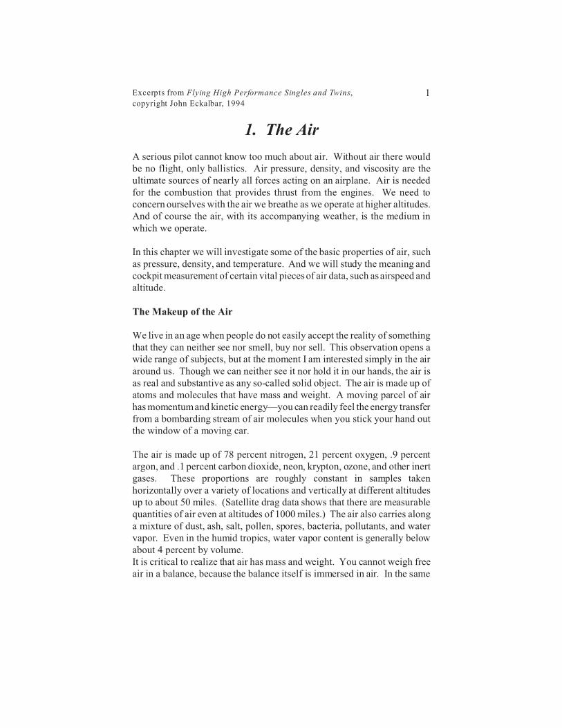
Figure 1. The four-stroke cycle engine.
2. The Normally Aspirated Engine
Internal combustion engines are a lot like people. They inhale air for itsoxygen, they eat "complex carbohydrates" (actually, hydrocarbons likeC8H17, for instance), they excrete H2O and CO2, and in the process theygenerate a lot of heat and noise and a little bit of useful work.
The basics of the Otto cycle spark ignition engine are shown in Figure 1.During the intake phase, the rotation of the crankshaft pulls the piston downin the cylinder. With the intake valve open, a fuel/air mixture flows intothe cylinder, due to the difference in pressure between the intake manifoldand the interior of the cylinder. Picture it this way: If the intake valve werestuck shut, the downward motion of the piston in the cylinder would createa partial vacuum in the cylinder, so with the valve open, the mixture willbe drawn into the cylinder.

Excerpts from Flying High Performance Singles and Twins,
copyright John Eckalbar, 199459
3. Turbocharging
We learned in the last chapter that the amount of horsepower generated bya given engine largely depends on the amount of fuel and air it burns. If weassume the fuel/air ratio, the mixture, is fixed, then we can say that powerdepends on the amount of air the engine inhales. But the expression"amount of air" needs to be clarified. A normally aspirated 550 cubic inchfour-stroke-cycle engine running at full throttle inhales a volume of a littleless than 550 cubic inches of ambient air with each two revolutions. (Thehigher the volumetric efficiency, the closer the volume will be to 550 cubicinches.) But power is not a function of the volume of air, it is a function ofthe mass of the air, i.e., its weight, or the number of molecules entering thecombustion chamber. A 550 cubic inch engine inhales a volume of about550 cubic inches of ambient air (per two revolutions) when it goes to fullthrottle at sea level on a standard day, and it inhales about 550 cubic inchesof ambient air in Denver on a hot day, but the number of molecules of airand the resulting power are very different in these two cases. With thereduced ambient air density at Denver, there are fewer air molecules to pairwith fuel molecules to support combustion. The result is less power fromthe same volume of air. (Remember, volume is not a measure of quantity,it is a measure of space.) And there is no point in giving the engine morefuel, because without more air, the fuel will not burn.
The purpose of a turbocharger is to stuff more molecules of air into thecombustion chamber. More air means more fuel can be burned, and thismeans more brake horsepower (BHP). This is particularly important inaircraft, which operate over a wide range of altitudes. If you want 250 BHPat 18,000 feet, essentially your choice is this: either install a very largenormally aspirated engine that can produce about 500 BHP at sea level, ora smaller turbocharged engine that gives you 250 BHP at sea level and 250BHP at 18,000 feet. The second alternative is more popular, because it ischeaper, lighter, and generally more efficient. (This does not say that aturbocharged 250 is cheaper, lighter, and more efficient than a normallyaspirated 250. That is not and probably never will be true.)
Excerpts from Flying High Performance Singles and Twins,
copyright John Eckalbar, 199481
4. Mixture
We begin with some facts. Later we will get into theory and operationalissues. Continental prints an interesting graph in its IO-550 Operator'sManual. The graph is redrawn here in Figure 1. As you look at this graph,imagine that we do an experiment while flying a Continental IO-550 in aBeech Bonanza or Baron. We set the MP at 24 inches and the RPM at2300, and then we gradually lean the mixture from full rich to the point oflean misfire. The fuel flow, shown on the horizontal axis, falls from about97 pounds per hour (pph) to about 62 pph. Our airplane is very wellinstrumented, and as we lean we watch the readout on four engineinstruments: EGT, CHT, BHP, and BSFC. EGT is exhaust gastemperature. CHT is cylinder head temperature. BHP is brake horsepower.And BSFC is brake specific fuel consumption—the number of pounds offuel being burned per hour divided by the present brake horsepower. Thecurves in Figure 1 show the four engine readings as we sweep through thevarious fuel flow values from rich to lean looking right to left. If you didthis same experiment at other power settings or with other engines, youwould see the same basic pattern, so we will take a closer look.
First, we define the fuel/air ratio. This is the number of pounds of fuelgoing into the engine per minute divided by the number of pounds of air perminute. As you read into this subject, you are just as likely to see referenceto the air/fuel ratio, which is nothing but the inverse of the fuel/air ratio.Gasoline engines run over a wide range of fuel/air ratios—from about .055to about .125. (That would mean air/fuel ratios of anywhere from 18/1 to8/1.) The amount of air entering a naturally aspirated engine is governedlargely by pressure altitude, outside air temperature, throttle position, andRPM. In our experiment, the amount of air entering the engine is roughlyconstant, since MP and RPM are fixed. And with throttle and prop controlsfixed, the amount of fuel in our experiment, and therefore the fuel/air ratio,is determined by the mixture control. Notice that even though our "powersetting" (MP and RPM) is fixed, the amount of power actually generatedstrongly depends on the fuel/air ratio of the charge. We will look at thesecurves one by one.
Excerpts from Flying High Performance Singles and Twins,
copyright John Eckalbar, 199498
5. Turbine Engines
When you graduate to turbine-powered airplanes, it is time to take aspecialized course for a week or so to study the airplane's systems,performance, procedures, and so on. A large part of such a course will dealwith the powerplant. You will cover the engine layout, systems, andlimitations as well as normal and emergency procedures. This chaptercannot possibly substitute for the detailed training you will need. Myobject here is to give you a brief introduction to the general features of gasturbine engines, so you will know a few basics and at least become anintelligent beginner or right-seat observer. What we will do is take a lookat the Pratt & Whitney Canada PT6A turboprop, which is the mostprevalent engine of this type.
The Layout of the PT6A
The photo on the previous page shows a cutaway view of one of the smallerversions of the PT6A. Figure 1 shows a highly simplified line drawing ofthe PT6A. Air enters near the rear of the engine and is directed to a three-stage axial compressor. An axial compressor is like a house fan; it movesair parallel to its axis of rotation. It is called "three-stage" simply becausethere are three of these compressors in a row. (Larger versions of the PT6Ahave four axial compressor stages.) Air leaving the third axial compressoris routed to a centrifugal compressor which pushes the air outward and thenforward toward the combustion chamber. The centrifugal compressor andthree (or four) axial compressors are mounted on a common shaft thatextends forward to the compressor turbine and aft to drive the accessories.The engine employs a compressor for the same reason a piston engine hasa turbocharger and a compression stroke, that is, to enable the engine togenerate more power with greater efficiency.
The combustion chamber is a perforated annular ring-shaped steel shellsurrounding the central axis of the engine. Air from the compressor sectionenters the combustion chamber through the perforations, and it is thenmixed with fuel, which is sprayed into the chamber at a rate dictated by thefuel control unit. There are two ignitor plugs in the combustion chamber.These are used for starting and to insure continued combustion duringoperations in heavy precipitation.
Excerpts from Flying High Performance Singles and Twins,
copyright John Eckalbar, 1994107
6. The Propeller
The job of the propeller is to translate the brake horsepower (BHP) at theend of the crankshaft into thrust. Imagine that we set an airplane on africtionless surface, tie a rope to the tail, and hook a scale to the rope. Wethen start the engine and measure the pull of the airplane in pounds as readfrom the scale. This pull is one of the basic forces in aerodynamics—it isthrust. The force is due to the fact that the propeller accelerates a mass ofair aft. Newton's third law says that for every force there is an equal andopposite force, or for every action there is an equal and opposite reaction.The counterpart to the rearward acceleration of a mass of air is an equalforward force called thrust. We are just seeing F = ma once more, but thistime the force, F, is called thrust.
In some applications, like performance analysis, it is better to think ofpower than thrust. Consider the magnitude TV, thrust times velocity,where V is true airspeed in feet per second. Since T is measured in pounds,TV must be foot-pounds per second. So 60TV would be foot-pounds perminute. Recall that one horsepower is the ability to do 33,000 foot-poundsof work per minute, so 60TV/33000, which equals TV/550, is thehorsepower equivalent of the amount of thrust being generated. This iscalled the thrust horsepower (THP). If we measure velocity in knots TAS,then THP = TV/326. So, for example, 500 pounds of thrust at 160 KTAScomes from 245 thrust horsepower (500*160/326 = 245).
Propeller Efficiency
If the propeller were 100 percent efficient, then all the BHP generated bythe engine would be converted to THP. But because of propeller skinfriction drag, interference between blades, kinetic energy lost to the trailingpropeller slipstream, and other factors, propeller efficiency is less than 100percent. Propeller efficiency, abbreviated with the Greek letter 0 (eta,pronounced "eighta") is given by
Excerpts from Flying High Performance Singles and Twins,
copyright John Eckalbar, 1994123
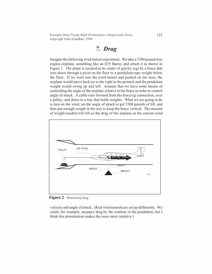
Figure 2. Measuring drag.
7. Drag
Imagine the following wind tunnel experiment. We take a 5300 pound twinengine airplane, something like an E55 Baron, and attach it as shown inFigure 1. The plane is secured at its center of gravity (cg) by a brace thatruns down through a pivot on the floor to a pendulum-type weight belowthe floor. If we went into the wind tunnel and pushed on the nose, theairplane would move back (or to the right in the picture) and the pendulumweight would swing up and left. Assume that we have some means ofcontrolling the angle of the airplane relative to the brace in order to controlangle of attack. A cable runs forward from the brace/cg connection, overa pulley, and down to a tray that holds weights. What we are going to dois turn on the wind, set the angle of attack to get 5300 pounds of lift, andthen put enough weight in the tray to keep the brace vertical. The amountof weight needed will tell us the drag of the airplane at the current wind
velocity and angle of attack. (Real wind tunnels are set up differently. Wecould, for example, measure drag by the rotation of the pendulum, but Ithink this presentation makes the issue more intuitive.)
Excerpts from Flying High Performance Singles and Twins,
copyright John Eckalbar, 1994143
8. Performance, Part I:Takeoff and Climb
We devoted a lot of effort in the early chapters toward improving ourunderstanding of air, engines, props, and airframe drag. To a serious pilot,these subjects ought to be interesting in their own right, but one of the mostimportant ancillary benefits of studying these subjects more deeply is animproved understanding of airplane performance. We will look atconventional performance issues in the next two chapters, and come backto the subject again later when we cover the aerodynamics of single-engineoperations in multiengine airplanes.
In the present chapter, I want to cover general issues pertaining to takeoffand climb performance, either in a single or a twin with both enginesoperating. Special attention is given to factors affecting performance,including especially high density altitudes.
Normal Takeoff
Before we get into the subject of takeoff performance, I want to mention afew points regarding takeoff technique, meaning the "stick and rudder"basics of handling the takeoff. I will not insult your intelligence with aprotracted discussion of the basics, just a few points related to somepatterns I have detected watching hundreds of pilots doing takeoffs in highperformance airplanes.
First, I have noticed that most pilots let the airplane stay on the ground toolong during the takeoff run. The result is that the airplane accelerates tomuch too high a speed before leaving the ground, and the little tires andwheels end up spinning furiously at liftoff. The undercarriage was notbuilt to run along the ground at speeds so far above the recommendedtakeoff and landing speeds; this is especially true if there is any tendencyto wheelbarrow, that is, to roll with a lot of weight on the nose gear. Whywould competent pilots stay on the ground way past the recommendedliftoff speed? Here is my theory.

Excerpts from Flying High Performance Singles and Twins,
copyright John Eckalbar, 1994163
9. Performance, Part II:Cruise and Landing
We continue our discussion of performance issues in this chapter. Ourfocus is on cruising for maximum range plus some general points regardinglandings. Specific issues related to multiengine flying, emergencies, orinstrument flying are taken up in detail in other chapters. Here weconcentrate on general issues of performance.
Cruising for Maximum MPG Did you ever wonder how you could get maximum miles per gallon fromyour airplane? I can think of several inflight situations that could make thisan important question. Maybe you have a trip planned that has a fairly longleg. If you fly the trip at your usual power setting, you will arrive withunacceptably low fuel reserves. (An hour is my personal minimum.)Stopping for fuel will add an hour to your trip. Could you use a differentpower setting, fly a little slower, and make the trip non-stop with goodreserves? Maybe you gain time by giving up a few minutes in cruise, whilesaving an hour fuel stop. Another reason you might find yourself sweatingout your range is that the weather got unexpectedly bad, and you arediverting toward the only decent alternate, which is some miles away. Ormaybe it is just a matter of economics. At $2 per gallon, you might caremore about speed than mpg, but what if it were $4 or $8?
Actually, you can learn a lot about getting maximum mpg in your airplaneby doing a simple inflight experiment. The next time you have nothing todo enroute try this: Set your RPM on the low side of what you normallyuse, and set your MP at the highest allowable value for your present RPM.Now lean to the leanest approved fuel flow. Maybe this will be peak EGT,or 20o C lean of peak, or whatever. Give the airspeed five minutes tostabilize, and record your MP, fuel flow, and indicated airspeed. (If you donot have good fuel flow data, just record MP and indicated airspeed.) Nowreduce MP by one inch, lean as before, and record MP, fuel flow, andindicated airspeed again after things stabilize. Continue the experimentuntil your power is so low you can no longer hold altitude. At home youcan draw a graph and/or do a little arithmetic and learn something aboutmaximum range for your airplane.
Excerpts from Flying High Performance Singles and Twins,
copyright John Eckalbar, 1994184
10. Instrument Flying by the Numbers
Until I know "the numbers" for a new airplane, I always feel more like aspectator than a pilot. Getting to know an airplane involves rememberinga lot of different numbers—max weights, fuel capacities, torque or MPlimits, and so on. When I refer to "the numbers" I do not mean all of thesefigures, though they are all important. The numbers I need to know beforeI feel at home in an airplane are the power/attitude/configurationcombinations to be used for the basic phases of flight.
Pilots who fly by the numbers are believers in the old saying, "Power plusattitude equals performance." I like this better when it is amended to say,"Power plus attitude plus configuration equals performance." (P + A + C= Pf) The idea is that if you set the power at a given level, like 25" MP and2500 RPM, and you put the airplane's nose at a fixed pitch attitude, like 5o
above the horizon, and you configure the airplane with, say, the gear andflaps up, you will get a certain, predictable performance outcome, meaninga definite airspeed and vertical speed. We will refer to the Power, Attitude,and Configuration setups as PACs.
The P + A + C = Pf equation seems to be an incontrovertible truism. Afterall, the airplane is a physical thing operating in a physical environment. Ithas power available and power required curves that determineairspeed/vertical speed tradeoffs along with an aoa and pitch attitude foreach power and airspeed combination. So since "the numbers" are alwaysat work, isn't everyone a "by-the-numbers" pilot?
No. The key thing that separates by-the-numbers pilots from others is thatwhen the numbers pilot wants to get the airplane to do something, he or shehas a preconceived idea of how to set up the airplane to accomplish thetask. If you asked a numbers pilot how he or she levels off at the MDA ona non-precision approach, you would get an answer that goes somethinglike this: "I add 5 inches MP. The nose comes up on its own withouttrimming to 2o above the horizon. The speed stays at 120 KIAS, and theVSI goes to zero." That is what I mean by a "preconceived idea." Incontrast, if you asked the same question to someone who does not fly by thenumbers, you would likely hear some blustering non-answer that goes like

Excerpts from Flying High Performance Singles and Twins,
copyright John Eckalbar, 1994219
11. Limitations: Airspeed and G-Load Factor
When an airplane is designed and certificated, the FAA and themanufacturer agree on a set of operating limitations. There are: (i) weightand center of gravity limitations, (ii) power plant limitations for MP, RPM,CHT, etc. (iii) minimum takeoff fuel, (iv) maximum slip duration, (v)airspeed and g-load factor limitations, and so on. These limitations areprinted in the Limitations section of the airplane flight manual, and at leastsome of them are also placed on placards in the aircraft. Under FAR 91.9,the pilot is required to abide by the airplane's limitations.
In this chapter we are concerned with the airspeed and g-load limitations.What exactly lies behind your handbook's warning to "not exceed 195KCAS except in smooth air and then only with caution"? And why doesthe maneuvering speed drop as the plane gets lighter? The purpose of thischapter is to increase your understanding of why these and other limits lookthe way they do. It is my feeling that your respect for these limits isproportional to your understanding of the reasons behind the limits. Andsince I think these limits should most definitely be respected, I want to dowhat I can to improve your understanding of their rationale. The discussioncan become fairly abstract and theoretical, and I will ask you to bear withme through it—this is important material, and I don't think pilotsunderstand it as well as they should. If an inherent curiosity aboutairplanes isn't enough, then let this be your motivation: There is nothingabstract about an airplane coming apart in the air.
And when an airplane does come apart, chances are good that the pilotallowed it to get outside its maneuver-gust envelope. This envelope,shown in Figure 7 at the end of this chapter, is a handy summary chartshowing the airspeed and g-load limits placed on the airplane. Derivingand explaining the envelope will be one of our main themes here. Whenyou understand it better, you will have more respect for your airplane'slimits, and that will make you a safer pilot. You will also finish thischapter with a generally better understanding of aerodynamics. And you
Excerpts from Flying High Performance Singles and Twins,
copyright John Eckalbar, 1994233
12. Strength, Stability, and Control
My motivation in writing this chapter is very similar to that for the previouschapter on airspeed and g-load factor limitations—I want you to take yourweight and balance limitations more seriously, and the best way to do thatis to improve your understanding of the reasons for the existence of theselimits.
When an airplane is certificated, it must pass a long list of tests. Many ofthese tests have to do with strength, stability, and control. As a rule, theairplane's weight and/or center of gravity influence the results of each test;that is, the airplane can pass a test at one weight or cg position, but will failat another. The FAA requires that the airplane pass each test at any pointin its approved weight and balance envelope. "Each requirement of thissubpart must be met at each appropriate combination of weight and centerof gravity within the range of loading conditions for which certification isrequested." (FAR 23.21(a)) And the FARs often mention that a test bepassed with the "center of gravity in the most unfavorable position." (FAR23.49(a)(6))
You can be sure the manufacturer wants to market an airplane with a wideweight and balance envelope, so the builder has an incentive to expand theenvelope as much as possible, while still passing the certification tests.Some airplane builders are more conservative than others, but they all feelthe pressure to keep the envelope wide. The end result is that when youexceed the weight and balance limits, your airplane is probably incapableof passing one or more of its certification requirements. Maybe it won't beable to climb in a balked landing. Maybe it will have an unrecoverablespin. Who knows? Whatever the case might be, you do not want to be theguinea pig who finds out.
In this chapter we will look first at the reasons for weight limits and thenconsider the rationale for cg limits.

Excerpts from Flying High Performance Singles and Twins,
copyright John Eckalbar, 1994273
14. Multiengine Aerodynamics
The aerodynamic theory behind multiengine operations has advancedconsiderably in the past few years, thanks largely to the work of LesterBerven, Melville Byington, Jr., and William P. Kelly, Jr. This chapterowes a lot to the work of these three, and I would recommend that everymultiengine pilot get copies of and study the works cited by these three atthe end of this chapter. If you are flying twins on one engine either the "oldway," banked five degrees toward the good engine, or the "old, old way,"wings level and ball in the center, your really need to study up, becausewhat you are doing is not only inefficient and old-fashioned, it isdangerous.
There is not much difference between the aerodynamics of a conventionaltwin versus a single, as long as both engines are running. But when oneengine is developing a lot of power and the other is shut down, or worseyet, windmilling, the differences between the conventional twin and thesingle are huge. We are going to focus here on three areas that are aboutequally responsible for fatal accidents during the takeoff phase in twinengine airplanes: (i) inadequate climb performance; (ii) loss of directionalcontrol; (3) stall/spin. An important sub-theme running through all threeof these issues is zero sideslip.
Engine-out Climb Performance
Suppose your plane requires 146 thrust horsepower (THP) to fly straightand level at 100 KCAS. We could say then that your "thrust horsepowerrequired" (THPr) at 100 KCAS is 146. The amount of thrust horsepowerrequired with the airplane in a given configuration is primarily dependentupon airspeed. At low airspeeds you need a lot of power to overcomeinduced drag, and at high airspeeds you need THPr to overcome parasitedrag. This produces a U-shaped THPr curve, as shown in Figure 1. If youwere flying straight and level at 100 KCAS and you pushed the throttles upenough to add 100 THP to the 146 you already have, what would theairplane do? The added energy has to show up somewhere, but where?
Excerpts from Flying High Performance Singles and Twins,
copyright John Eckalbar, 1994300
15. Multiengine Operations
This is the second of two chapters on multiengine flying. The presentchapter covers practical, operational issues. Having covered the theory inthe last chapter, I am now interested more in how you do something than inthe pure theory detailing why. This chapter primarily is a collection ofplain English suggestions, rather than a lot of aerodynamic analysis. Wewill start at the beginning, with planning, and then cover the basic phasesof flight in logical order.
Takeoff Planning
You must plan your takeoff long before you start the engines and head forthe departure end of the runway. In fact, the best time to do the takeoffplanning is prior to your flight into the airport you now plan to leave.Many times you can easily get into an airport only to find that it is a realchallenge to get back out safely. This is most likely to be the case in anormally aspirated airplane at high altitude, but it is a problem worthwatching for in any short field operation. If there is any doubt at all, checkyour takeoff requirements before you land.
We should answer several performance questions in our takeoff planning.We will consider them in turn.
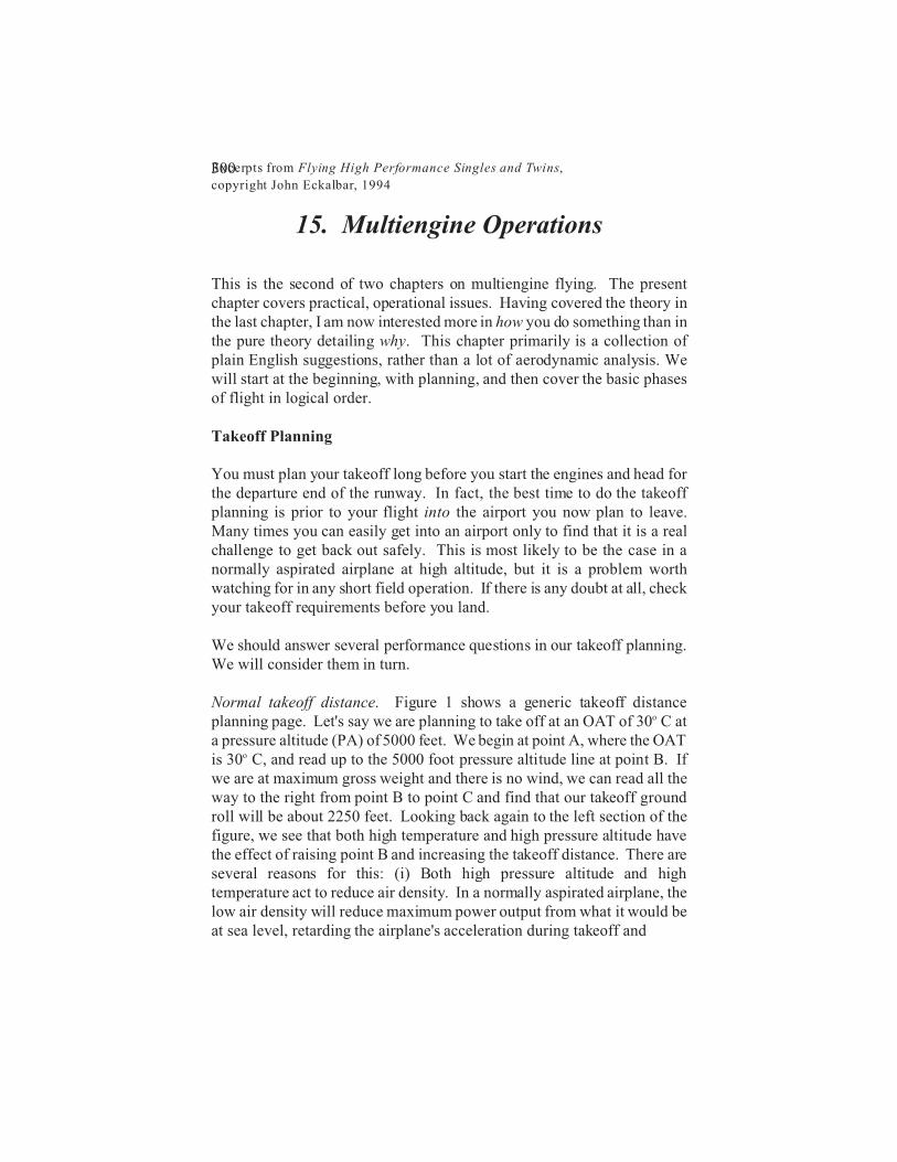
Normal takeoff distance. Figure 1 shows a generic takeoff distanceplanning page. Let's say we are planning to take off at an OAT of 30o C ata pressure altitude (PA) of 5000 feet. We begin at point A, where the OATis 30o C, and read up to the 5000 foot pressure altitude line at point B. Ifwe are at maximum gross weight and there is no wind, we can read all theway to the right from point B to point C and find that our takeoff groundroll will be about 2250 feet. Looking back again to the left section of thefigure, we see that both high temperature and high pressure altitude havethe effect of raising point B and increasing the takeoff distance. There areseveral reasons for this: (i) Both high pressure altitude and hightemperature act to reduce air density. In a normally aspirated airplane, thelow air density will reduce maximum power output from what it would beat sea level, retarding the airplane's acceleration during takeoff and
Excerpts from Flying High Performance Singles and Twins,
copyright John Eckalbar, 1994330
16. Engine Failure in Single-engine Airplanes
We have just devoted two chapters to the analysis of multiengine operations,with special emphasis on engine failures. One of the basic lessons is thatyou must have a plan in mind prior to takeoff. You need to be thinking,"What will I do if the engine fails here? And what if it fails there?" This isno less true with regard to single-engine airplanes, though the subject getsmuch less attention. In this chapter I will focus on the techniques forhandling an engine failure in a single-engine airplane. My special interestis the issue of a turn back to the airport following a failure. Engine Failure on Takeoff
Every year needless tragedies occur as pilots try the impossible: a turn backto the airport from too low after an engine failure on takeoff. This promptsthe most commonly heard advice on the subject, namely, don't try to turnback, land straight ahead. But is this always the best course? There mustbe an altitude high enough that you can make it back safely. How high is it?There must be an optimum path to follow, but what is it? A 180 degreeturn? A 30/210 teardrop? A 90/270, or what? There must be an optimumglide speed. Is it the speed for best glide range in your POH? There shouldbe an optimum bank angle to use in the turn. Is it 30 degrees, 60 degrees, orsomething else? And what about the effects of wind, density altitude, andaircraft weight? I will address these subjects in the following paragraphs.Some of the answers will depend upon the particular aircraft being flown,but surprisingly, some answers are the same for all aircraft. One majorresult is that a unique optimum bank angle, 45 degrees, works for all aircraft.
Memory items. Before we get to these subjects, I should point out that thepilot must immediately lower the nose to maintain a safe angle of attack, andthat he or she should then without hesitation perform the memory items fromthe engine failure checklist in the POH. These items vary from airplane toairplane, but usually involve such actions as switching tanks, trying fuelpumps, checking ignition and power levers, and pulling the prop controlback. (You pull the prop handle back because the sink rate is about

Excerpts from Flying High Performance Singles and Twins,
copyright John Eckalbar, 1994343
17. Pressurization
Having a turbocharger or a turbine powerplant really tempts you to higheraltitudes. According to the Cessna T210 POH, for instance, you can expectto do 161 KTAS on 98 pph at 5000 feet and 183 KTAS on 98 pph at 20,000feet. And aside from speed or economy, there are a lot of advantages tooperating at high altitudes. You are more likely to be over the weather.There is less traffic. Radio reception is better. The air is usually smoother.And once in a while, there will be a tremendous tailwind.
Your plane may love to go high, but your body does not. It needs oxygen.At sea level ISA, where the pressure of the air is about 14.7 psi and theoxygen content is about 21 percent, the "partial pressure" of the oxygen is3.087 psi (= 14.7 times .21). There are essentially two strategies for gettingoxygen while operating at high altitudes. One is to increase theconcentration of the oxygen in the air you breathe while letting the airpressure drop with the rise in altitude. This is what an oxygen mask does.If you breathed 100 percent oxygen at about 38,000 feet, the oxygen partialpressure would be about the same as at sea level. (Unless stated otherwise,the altitudes given in this chapter are pressure altitudes.) But this approachhas never been very popular with pilots, passengers, and pets. The masksare uncomfortable, and oxygen is a hassle to acquire. The other approachis to raise the pressure of the air in the cabin above that of the outside air.The technique is simple enough in principle—you more or less seal up thecabin and use the turbocharger or compressor bleed air from a turbine engineto raise the cabin pressure by pumping ambient air into the cabin.
In this chapter we review the basic ingredients of the pressurization systemand consider both the normal and emergency procedures related to thesystem.
Typical Pressurization Layout
Figure 1 shows the layout of a generic pressurization system. A line tees inbetween the turbocharger compressor and the intake manifold and bleedscompressed air past a dump valve, through a restrictor called a "sonic
Excerpts from Flying High Performance Singles and Twins,
copyright John Eckalbar, 1994371
19. Storm Avoidance Hardware
I will not insult your intelligence by lecturing on the hazards ofthunderstorms. Any serious pilot is well aware of the reality of the threat.In this chapter I will cover the characteristics and proper use of severaldifferent pieces of storm avoidance hardware. Of course, the best hardwareis your eyes. If the sky ahead looks ugly, stay out of it, regardless of whatyour electronics say. And the best software is your judgment. If your gutfeeling is that carrying on is not the best idea, then it isn't. The weather willalmost certainly be better tomorrow, if not in two hours. None of thehardware discussed below is meant to guide you through an active area ofthunderstorms. It is meant to help you stay out of it. Radar
"Radar" stands for RAdio Detection And Ranging. Just as a sound wavebounces off an object and returns as an echo to a listener, or a light wavereflects from an object and returns as a visual image to an observer, so tooa microwave can bounce off an object and return to a receiver.
Modern X-band airborne weather radars transmit a short duration, fairlyhigh power cone-shaped pulse with a frequency of 9375 MHz. The pulsetravels at the speed of light. After the pulse is sent, the transmitter shutsdown, and a receiver comes up to wait for an echo. Some objects reflect thepulse, bouncing a part of the original signal back to the airborne antenna,which has momentarily ceased transmitting and is now listening for thereturn. The signal is then sent to the receiver, which notes three things: (i)the round-trip time for the pulse, (ii) the strength of the returning signal, and(iii) the direction the antenna was pointed when the pulse was sent and theecho was heard. The round trip time for the pulse is easily converted intodistance, since the speed of the signal is known. It takes 12.36 microsecondsfor each two-mile round trip, or for each one mile to the target. The strengthof the signal tells about the size and the reflectivity of the target being struckby the pulse. And the direction the antenna was pointing identifies theazimuth of the target, i.e., its relative bearing in relation to the nose of theaircraft.
Excerpts from Flying High Performance Singles and Twins,
copyright John Eckalbar, 1994386
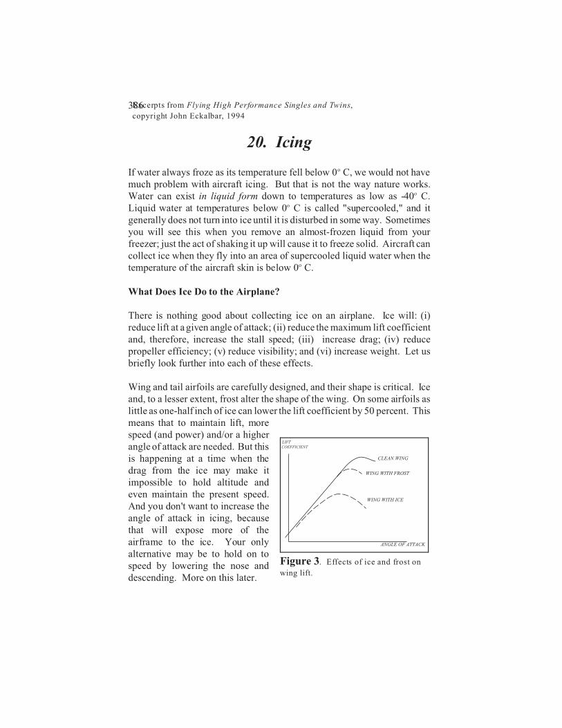
Figure 3. Effects of ice and frost on
wing lift.
20. Icing
If water always froze as its temperature fell below 0o C, we would not havemuch problem with aircraft icing. But that is not the way nature works.Water can exist in liquid form down to temperatures as low as -40o C.Liquid water at temperatures below 0o C is called "supercooled," and itgenerally does not turn into ice until it is disturbed in some way. Sometimesyou will see this when you remove an almost-frozen liquid from yourfreezer; just the act of shaking it up will cause it to freeze solid. Aircraft cancollect ice when they fly into an area of supercooled liquid water when thetemperature of the aircraft skin is below 0o C.
What Does Ice Do to the Airplane?
There is nothing good about collecting ice on an airplane. Ice will: (i)reduce lift at a given angle of attack; (ii) reduce the maximum lift coefficientand, therefore, increase the stall speed; (iii) increase drag; (iv) reducepropeller efficiency; (v) reduce visibility; and (vi) increase weight. Let usbriefly look further into each of these effects.
Wing and tail airfoils are carefully designed, and their shape is critical. Iceand, to a lesser extent, frost alter the shape of the wing. On some airfoils aslittle as one-half inch of ice can lower the lift coefficient by 50 percent. Thismeans that to maintain lift, morespeed (and power) and/or a higherangle of attack are needed. But thisis happening at a time when thedrag from the ice may make itimpossible to hold altitude andeven maintain the present speed.And you don't want to increase theangle of attack in icing, becausethat will expose more of theairframe to the ice. Your onlyalternative may be to hold on tospeed by lowering the nose anddescending. More on this later.