excitation system
DESCRIPTION
Excitation System of GeneratorTRANSCRIPT

EXCITATION SYSTEMSEXCITATION SYSTEMS
1539pk
Copyright © P. KundurThis material should not be used without the author's consent

)
Excitation SystemsExcitation Systems
1. Functions and Performance
Requirements
2. Elements of an Excitation System
3. Types of Excitation Systems
Outline
1539pkES- 1
3. Types of Excitation Systems
4. Control and Protection Functions
5. Modeling of Excitation Systems

)
Functions and Performance Functions and Performance
Requirements of Excitation SystemsRequirements of Excitation Systems
� The functions of an excitation system are
� to provide direct current to the synchronous
generator field winding, and
� to perform control and protective functions
essential to the satisfactory operation of the
power system
� The performance requirements of the excitation
system are determined by
1539pkES- 2
a) Generator considerations:
� supply and adjust field current as the generator output varies within its continuous capability
� respond to transient disturbances with field forcingconsistent with the generator short term capabilities:
- rotor insulation failure due to high field voltage
- rotor heating due to high field current
- stator heating due to high VAR loading
- heating due to excess flux (volts/Hz)
b) Power system considerations:
� contribute to effective control of system voltage and improvement of system stability
)
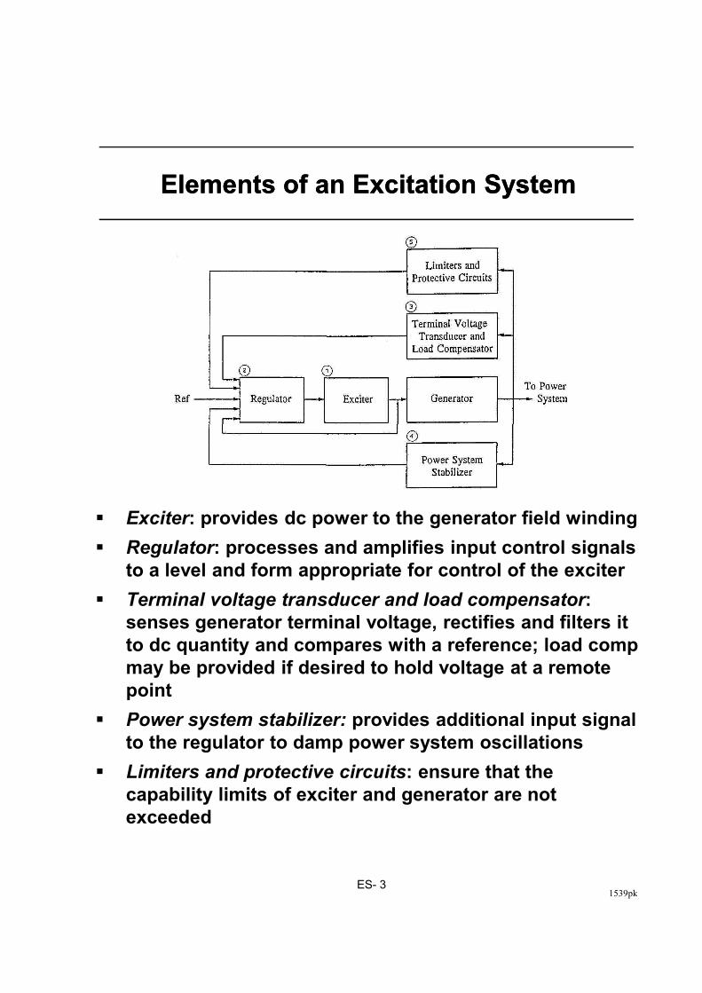
Elements of an Excitation SystemElements of an Excitation System
1539pkES- 3
� Exciter: provides dc power to the generator field winding
� Regulator: processes and amplifies input control signals
to a level and form appropriate for control of the exciter
� Terminal voltage transducer and load compensator:
senses generator terminal voltage, rectifies and filters it
to dc quantity and compares with a reference; load comp
may be provided if desired to hold voltage at a remote
point
� Power system stabilizer: provides additional input signal
to the regulator to damp power system oscillations
� Limiters and protective circuits: ensure that the
capability limits of exciter and generator are not
exceeded

)
Types of Excitation SystemsTypes of Excitation Systems
Classified into three broad categories based on the
excitation power source:
• DC excitation systems
• AC excitation systems
• Static excitation systems
1. DC Excitation Systems:
• utilize dc generators as source of power;
1539pkES- 4
• utilize dc generators as source of power;
driven by a motor or the shaft of main generator;
self or separately excited
• represent early systems (1920s to 1960s);
lost favor in the mid-1960s because of large size;
superseded by ac exciters
• voltage regulators range from the early non-
continuous rheostatic type to the later system
using magnetic rotating amplifiers
)
Figure 8-2 shows a simplified schematic of a typical
dc excitation system with an amplidyne voltage
regulator
• self-excited dc exciter supplies current to the
main generator field through slip rings
• exciter field controlled by an amplidyne which
provides incremental changes to the field in a
buck-boost scheme
• the exciter output provides rest of its own field by
self-excitation
2. AC Excitation Systems:
1539pkES- 5
2. AC Excitation Systems:
• use ac machines (alternators) as source of power
• usually, the exciter is on the same shaft as the
turbine-generator
• the ac output of exciter is rectified by either
controlled or non-controlled rectifiers
• rectifiers may be stationary or rotating
• early systems used a combination of magnetic
and rotating amplifiers as regulators; most new
systems use electronic amplifier regulators

1539pkES- 6
Figure 8.2: DC excitation system with amplidyne voltage regulators

)
2.1 Stationary rectifier systems:
• dc output to the main generator field supplied through slip rings
• when non-controlled rectifiers are used, the regulator controls the field of the ac exciter; Fig. 8.3 shows such a system which is representative of GE-ALTERREX system
• When controlled rectifiers are used, the regulator directly controls the dc output voltage of the exciter; Fig. 8.4 shows such a system which is representative of GE-ALTHYREX system
2.2 Rotating rectifier systems:
1539pkES- 7
2.2 Rotating rectifier systems:
• the need for slip rings and brushes is eliminated; such systems are called brushless excitation systems
• they were developed to avoid problems with the use of brushes perceived to exist when supplying the high field currents of large generators
• they do not allow direct measurement of generator field current or voltage

)
Figure 8.3: Field controlled alternator rectifier excitation system
1539pkES- 8
Figure 8.4: Alternator supplied controlled-rectifier excitation system

)
1539pkES- 9
Figure 8.5: Brushless excitation system

)
3. Static Excitation Systems:
• all components are static or stationary
• supply dc directly to the field of the main
generator through slip rings
• the power supply to the rectifiers is from the main
generator or the station auxiliary bus
3.1 Potential-source controlled rectifier system:
• excitation power is supplied through a
transformer from the main generator terminals
• regulated by a controlled rectifier
• commonly known as bus-fed or transformer-fed
static excitation system
• very small inherent time constant
1539pkES- 10
• very small inherent time constant
• maximum exciter output voltage is dependent on
input ac voltage; during system faults the
available ceiling voltage is reduced
Figure 8.6: Potential-source controlled-rectifier excitation system

)
3.2 Compound-source rectifier system:
• power to the exciter is formed by utilizing current
as well as voltage of the main generator
• achieved through a power potential transformer
(PPT) and a saturable current transformer (SCT)
• the regulator controls the exciter output through
controlled saturation of excitation transformer
• during a system fault, with depressed generator
voltage, the current input enables the exciter to
provide high field forcing capability
An example is the GE SCT-PPT.
1539pkES- 11
3.3 Compound-controlled rectifier system:
• utilizes controlled rectifiers in the exciter output
circuits and the compounding of voltage and
current within the generator stator
• result is a high initial response static system with
full "fault-on" forcing capability
An example is the GE GENERREX system.

)
Fig. 8.7: Compound-source rectifier excitation system
1539pkES- 12
Figure 8.8: GENERREX compound-controlled rectifier excitation system ©IEEE1976 [16]
)
Control and Protective FunctionsControl and Protective Functions
� A modern excitation control system is much more
than a simple voltage regulator
� It includes a number of control, limiting and
protective functions which assist in fulfilling the
performance requirements identified earlier
� Figure 8.14 illustrates the nature of these functions
and the manner in which they interface with each
other
1539pkES- 13
� any given system may include only some or all of
these functions depending on the specific
application and the type of exciter
� control functions regulate specific quantities at
the desired level
� limiting functions prevent certain quantities from
exceeding set limits
� if any of the limiters fail, then protective functions
remove appropriate components or the unit from
service

)
1539pkES- 14
Figure 8.14: Excitation system control and protective circuits

� AC Regulator:
� basic function is to maintain generator stator voltage
� in addition, other auxiliaries act through the ac
regulator
� DC Regulator:
� holds constant generator field voltage (manual
control)
� used for testing and startup, and when ac regulator is
faulty
� Excitation System Stabilizing Circuits:
� excitation systems with significant time delays have
poor inherent dynamic performance
� unless very low steady-state regulator gain is used,
1539pkES- 15
� unless very low steady-state regulator gain is used,
the control action is unstable when generator is on
open-circuit
� series or feedback compensation is used to improve
the dynamic response
� most commonly used form of compensation is a
derivative feedback (Figure 8.15)
Figure 8.15: Derivative feedback excitation control system stabilization

)
� Power System Stabilizer (PSS):
� uses auxiliary stabilizing signals (such as shaft
speed, frequency, power) to modulate the
generator field voltage so as to damp system
oscillations
� Load Compensator:
� used to regulate a voltage at a point either within
or external to the generator
� achieved by building additional circuitry into the
AVR loop (see Fig. 8.16)
� with RC and XC positive, the compensator
1539pkES- 16
� with RC and XC positive, the compensator
regulates a voltage at a point within the
generator;
� used to ensure proper sharing VARs between generators bussed together at their terminals
� commonly used with hydro units and cross-compound thermal units
� with RC and XC negative, the compensator
regulates voltage at a point beyond the generator
terminals
� commonly used to compensate for voltage drop across step-up transformer when generators are connected through individual transformers
1539pkES- 17
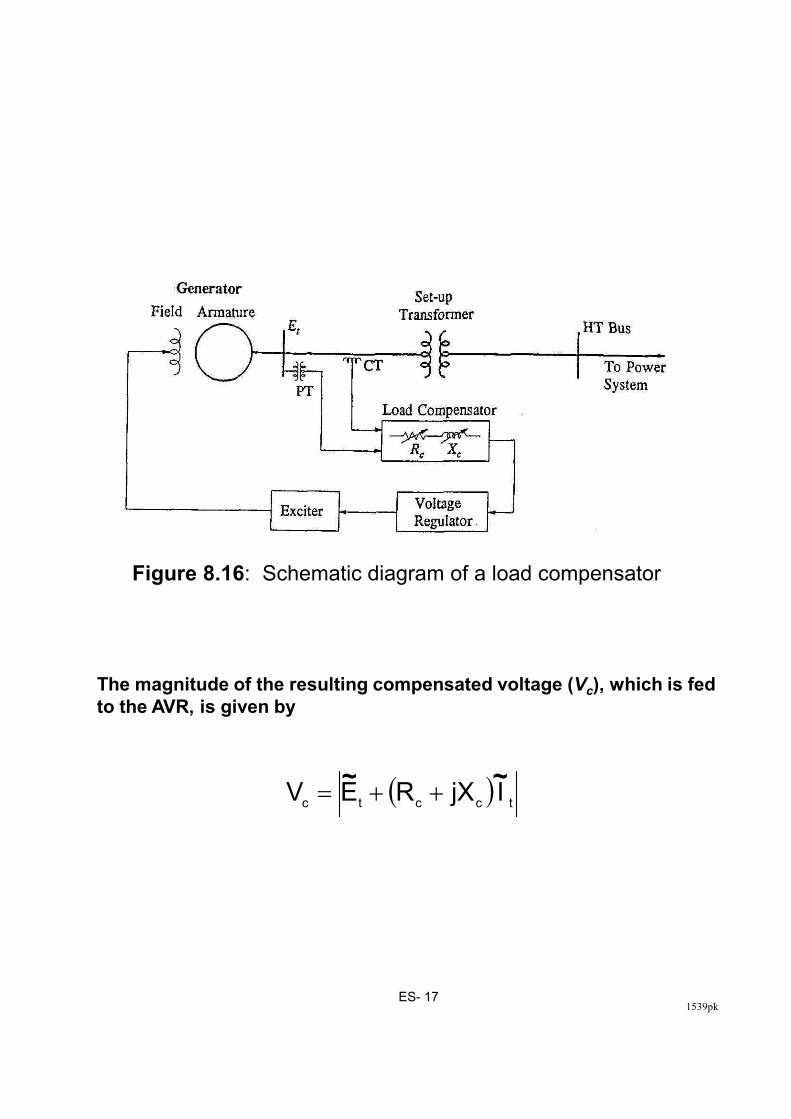
Figure 8.16: Schematic diagram of a load compensator
The magnitude of the resulting compensated voltage (Vc), which is fed
to the AVR, is given by
( )tcctc
IjXREV~~
++=

)
� Underexcitation Limiter (UEL):
� intended to prevent reduction of generator excitation to a level where steady-state (small-signal) stability limit or stator core end-region heating limit is exceeded
� control signal derived from a combination of either voltage and current or active and reactive power of the generator
� a wide variety of forms used for implementation
� should be coordinated with the loss-of-excitation protection (see Figure 8.17)
� Overexcitation Limiter (OXL)
� purpose is to protect the generator from overheating due to prolonged field overcurrent
� Fig. 8.18 shows thermal overload capability of
1539pkES- 18
� Fig. 8.18 shows thermal overload capability of the field winding
� OXL detects the high field current condition and, after a time delay, acts through the ac regulator to ramp down the excitation to about 110% of rated field current; if unsuccessful, trips the ac regulator, transfers to dc regulator, and repositions the set point corresponding to rated value
� two types of time delays used: (a) fixed time, and (b) inverse time
� with inverse time, the delay matches the thermal capability as shown in Figure 8.18

Figure 8.17: Coordination between UEL, LOE relay and stability limit
1539pkES- 19
Figure 8.18: Coordination of over-excitation limiting with field thermal capability

�
� Volts per Hertz Limiter and Protection:
� used to protect generator and step-up
transformer from damage due to excessive
magnetic flux resulting from low frequency and/or
overvoltage
� excessive magnetic flux, if sustained, can cause
overheating and damage the unit transformer and
the generator core
� Typical V/Hz limitations:
V/Hz (p.u.) 1.25 1.2 1.15 1.10 1.05
1539pkES- 20
� V/Hz limiter (or regulator) controls the field
voltage so as to limit the generator voltage when
V/Hz exceeds a preset value
� V/Hz protection trips the generator when V/Hz
exceeds the preset value for a specified time
Note: The unit step-up transformer low voltage
rating is frequently 5% below the generator
voltage rating
V/Hz (p.u.) 1.25 1.2 1.15 1.10 1.05
Damage Time in Minutes
GEN 0.2 1.0 6.0 20.0 ∞
XFMR 1.0 5.0 20.0 ∞ ∞

Modeling of Excitation SystemsModeling of Excitation Systems
� Detail of the model required depends on the
purpose of study:
� the control and protective features that impact
on transient and small-signal stability studies
are the voltage regulator, PSS and excitation
control stabilization
� the limiter and protective circuits normally need
to be considered only for long-term and voltage
stability studies
1539pkES- 21
stability studies
� Per Unit System:
Several choices available:
a) per unit system used for the main generator field
circuit
� chosen to simplify machine equations but not considered suitable for exciter quantities; under normal operating conditions field voltage in the order of 0.001 (too small)
b) per unit system used for excitation system
specifications
� rated load filed voltage as one per unit
� not convenient for system studies

8.6.2 Modeling of Excitation System Components
The basic elements which form different types of
excitation systems are the dc exciters (self or separately
excited); ac exciters; rectifiers (controlled or non-
controlled); magnetic, rotating, or electronic amplifiers;
excitation system stabilizing feedback circuits; signal
sensing and processing circuits
Separately excited dc exciter
1539pkES- 22
Figure 8.26: Block diagram of a dc exciter
Self-excited dc exciter
The block diagram of Fig. 8.26 also applies to the self-
excited dc exciter. The value of KE, however, is now equal
to Ref/Rg-1 as compared to Ref/Rg for the separately excited
case.
The station operators usually track the voltage regulator
by periodically adjusting the rheostat setpoint so as to
make the voltage regulator output zero. This is accounted
for by selecting the value of KE so that the initial value of
VR is equal to zero. The parameter KE is therefore not
fixed, but varies with the operating condition.

Figure 8.28: Block diagram of an ac exciter
AC Exciter and Rectifier
1539pkES- 23
Figure 8.28: Block diagram of an ac exciter
Figure 8.30: Rectifier regulation model

ч
Figure 8.34: (a) Integrator with windup limits
Representation:
System equation:
Limiting action:
Windup and Non-Windup Limits
1539pkES- 24
Figure 8.34: (b) Integrator with non-windup limits
Representation:
System equation:
Limiting action:

8.6.3 Modeling of Complete Excitation Systems
Figure 8.39 depicts the general structure of a detailed
excitation system model having a one-to-one
correspondence with the physical equipment. While this
model structure has the advantage of retaining a direct
relationship between model parameters and physical
parameters, such detail is considered too great for general
system studies. Therefore, model reduction techniques are
used to simplify and obtain a practical model appropriate
for the type of study for which it is intended.
The parameters of the reduced model are selected such that
the gain and phase characteristics of the reduced model
match those of the detailed model over the frequency range
of 0 to 3 Hz. In addition, all significant nonlinearities that
1539pkES- 25
of 0 to 3 Hz. In addition, all significant nonlinearities that
impact on system stability are accounted for. With a
reduced model, however, direct correspondence between
the model parameters and the actual system parameters is
generally lost.
Figure 8.39: Structure of a detailed excitation system model

+
Standard IEEE ModelsStandard IEEE Models
� IEEE has standardized 12 model structures for
representing the wide variety of excitation systems
currently in use (see IEEE Standard 421.5-1992):
� these models are intended for use in transient
and small-signal stability studies
� Figures 8.40 to 8.43 show four examples
1539pkES- 26

1. Type DC1A Exciter model
Figure 8.40: IEEE type DC1A excitation system model. ©IEEE 1991[8]
The type DC1A exciter model represents field controlled dc
communtator exciters, with continuously acting voltage regulators.
The exciter may be separately excited or self excited, the latter type
being more common. When self excited, KE is selected so that initially
VR=0, representing operator action of tracking the voltage regulator by
periodically trimming the shunt field rheostat set point.
1539pkES- 27
2. Type AC1A Exciter model
Figure 8.41: IEEE type AC1A excitation system model. ©IEEE 1991[8]
The type AC1A exciter model represents a field controlled alternator
excitation system with non-controlled rectifiers, applicable to a
brushless excitation system. The diode rectifier characteristic imposes
a lower limit of zero on the exciter output voltage. The exciter field
supplied by a pilot exciter, and the voltage regulator power supply is
not affected by external transients.

ш
3. Type AC4A exciter model
The type AC4A exciter model represents an alternator supplied controlled
rectifier excitation system - a high initial response excitation system
utilizing full wave thyristor bridge circuit. Excitation system stabilization
is usually provided in the form of a series lag-lead network (transient gain
reduction). The time constant associated with the regulator and firing of
thyristors is represented by TA. The overall gain is represented by KA. The
rectifier operation is confined to mode 1 region. Rectifier regulation
effects on exciter output limits are accounted for by constant KC.
Figure 8.42: IEEE type AC4A excitation system model © IEEE 1991 [8]
1539pkES- 28
4. Type ST1A exciter model
effects on exciter output limits are accounted for by constant KC.
The type ST1A exciter model represents potential-source controlled-rectifier
systems. The excitation power is supplied through a transformer from
generator terminals; therefore, the exciter ceiling voltage is directly
proportional to generator terminal voltage. The effect of rectifier regulation
on ceiling voltage is represented by KC. The model provides flexibility to
represent series lag-lead or rate feedback stabilization. Because of very
high field forcing capability of the system, a field current limiter is
sometimes employed; the limit is defined by lLR and the gain by KLR.
Figure 8.43: IEEE type ST1A excitation system model © IEEE 1991 [8]

絀ш
Modeling of LimitersModeling of Limiters
� Standard models do not include limiting circuits;
these do not come into play under normal
conditions
� These are, however, important for long-term and
voltage stability studies
� Implementation of these circuits varies widely
� models have to be established on a case by case
basis
1539pkES- 29
basis
� Figure 8.47 shows as an example the model of a
field current limiter

ш
(a) Block diagram representation
1539pkES- 30
(b) Limiting characteristics
Figure 8.47: Field-current limiter model