executive summary · web viewproblem statement calvin college currently maintains a fleet of around...
TRANSCRIPT
Team 4: Volts-Wagon
Project Proposal Feasibility StudyDesign Report
Thomas Brown, Garrick Hershberger, Jee Myung Kim, Andrew White
Engineering 339: Senior Design Project
Calvin College

© 2015, Thomas Brown, Garrick Hershberger, Jee Myung Kim, Andrew White, and Calvin College
1 | P a g e
Executive Summary
With declining fuel reserves, alternative energy solutions must be sought out. This is increasingly apparent for Calvin College, as its aging fleet of cars, trucks, vans, and golf carts are fossil fuel powered. To prepare for the future, Calvin College will need to obtain and maintain vehicles powered with alternative fuel sources. This project proposes to offer a remedy to this problem in the form of a small electric vehicle for on-campus use that will replace a standard gas-powered golf cart. This vehicle will be charged by low cost wall charging assisted with solar power.
Team Volts-Wagon is a four-person team. The team has three students pursuing a BSE with a mechanical concentration and one student pursuing a BSE with an electrical concentration at Calvin College.
The team proposes that the design be a four wheeled, four person electric vehicle with a max speed of 20 miles per hour (mph). This vehicle would be designed to travel a distance of five miles and be charged from a standard 110 volt electrical outlet.
2 | P a g e
ContentsExecutive Summary.....................................................................................................................................2
1. Introduction.........................................................................................................................................5
a. Problem Statement..........................................................................................................................5
b. Design Norms...................................................................................................................................5
2. Project Management...........................................................................................................................6
a. Team Organization...........................................................................................................................6
i. Thomas Brown..................................................................................................................................6
ii. Garrick Hershberger.........................................................................................................................6
iii. Jee Myung Kim.................................................................................................................................6
iv. Andrew White..................................................................................................................................6
b. Team Picture....................................................................................................................................7
3. Requirements......................................................................................................................................8
a. Functional.........................................................................................................................................8
a. Performance.....................................................................................................................................8
4. Research..............................................................................................................................................9
5. Main Component Selection...............................................................................................................10
a. Vehicle Frame.................................................................................................................................10
b. Electric Motor and Controller.........................................................................................................10
c. Battery Pack and Power Supply......................................................................................................10
6. Design................................................................................................................................................11
a. Criteria............................................................................................................................................11
a. Alternatives....................................................................................................................................11
b. Decisions........................................................................................................................................11
7. Safety Concerns.................................................................................................................................13
8. Calculations.......................................................................................................................................15
a. Energy Calculations........................................................................................................................15
b. Finite Element Analysis...................................................................................................................16
9. Cost Analysis......................................................................................................................................17
a. Operational Cost.............................................................................................................................17
b. Production Cost Estimate...............................................................................................................18
3 | P a g e
10. Business Plan.....................................................................................................................................20
11. Conclusion.........................................................................................................................................21
12. Acknowledgements...........................................................................................................................22
13. Appendices........................................................................................................................................23
a. Bibliography....................................................................................................................................23
b. Calculations....................................................................................................................................24
c. Figures............................................................................................................................................27
d. Parts Documentation......................................................................................................................28
i. Motor.........................................................................................................................................28
ii. Motor Controller........................................................................................................................29
iii. Charger......................................................................................................................................30
iv. Electric Schematic......................................................................................................................31
4 | P a g e
1. Introduction
a. Problem Statement
Calvin College currently maintains a fleet of around 15 gasoline powered golf carts. These golf carts are expensive to purchase, maintain, and fuel. The aim of this project is the creation of a lightweight, inexpensive, homegrown alternative to the current problem. The goal is to design a vehicle that could be used in place of Calvin Colleges current golf carts and provide transportation for faculty and staff around campus.
John Britton of the Student Development Office (SDO) has requested a vehicle of this type and has become our client. He is looking for a vehicle that is more sustainable and better looking than the standard Calvin golf carts so that he and his department can stand out. The team has consulted him on multiple occasions for what he would like for the vehicle design.
The major appeal of this vehicle is its ability to be much less expensive than other alternatives that Calvin College could purchase or obtain. This vehicle would also be an excellent way for the institution to demonstrate the abilities of its engineering program in a way that prospective students, alumni, and donors would see during campus visits. This vehicle would also have the additional benefit of being more sustainable that the current vehicles that Calvin uses.
b. Design Norms
- Trust:
The vehicle must be trustworthy and dependable. It should be constructed to go beyond its
design parameters and be reliable. This product will be used on a regular basis by college staff
and should be designed and constructed to the highest standards.
- Integrity:
This project must be carefully designed and constructed to be ergonomic, comfortable and also
useful. It must work for the staff who use it, to make their job easier. It must also be intuitive to
use and accomplish its task with the minimum amount of effort on the user.
- Caring:
This product must be pleasing and take into account the method of use and how often it will be
used. The final design is helpful and not harmful to those who not only use but maintain it.
5 | P a g e
- Stewardship:
Calvin College is an institution of finite resources, both financially and environmentally. With
budgets being tight and fuel becoming more expensive, Calvin needs new ways to do more with
less, while minimizing any damage to the environment. The team’s vehicle is designed to reduce
Calvin College’s dependence on fossil fuels.
2. Design Team
a. Thomas Brown
Thomas is pursuing a Bachelors of Science in Engineering with an International Mechanical Engineering Concentration at Calvin College. He is from Grand Rapids, MI. He works for Calvin College’s Student Activities Office organizing student events based around video games, and enjoys playing them in his free time. After graduating in May 2015 he plans to find a job in mechanical design or manufacturing.
b. Garrick Hershberger
Garrick is pursuing a Bachelors of Science in Engineering with an International Mechanical Engineering Concentration with an international distinction at Calvin College. He is from Nashville, MI. He works for Calvin College Physical Plant in the Transportation department. He enjoys playing rugby for Calvin Men’s Rugby in his spare time. After graduating in May 2015 he plans to find a job in mechanical design or manufacturing engineering.
c. Jee Myung Kim
Jee is a senior student at Calvin College pursuing a Bachelors of Science in Engineering with an International Mechanical Engineering Concentration at Calvin College and a minor in mathematics. He was born in South Korea and lived in China for half of his childhood before he came to United States for college education. He enjoys playing tennis and listening to music. He works for Calvin College Engineering Department as a grader. After graduating in May 2015 he plans to enter a graduate school.
d. Andrew White
Andrew is pursuing a Bachelors of Science in Engineering with an Electrical Engineering Concentration at Calvin College. He is from Howell, MI. In his free time he enjoys Ballroom dancing, singing, and playing piano in his free time. After graduating in May 2015 he plans to find a job in Research and Development, Troubleshooting, or Manufacturing.
6 | P a g e
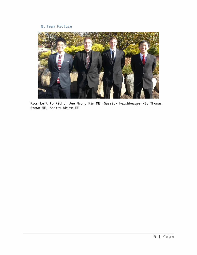
e. Team Picture
7 | P a g e
From Left to Right: Jee Myung Kim ME, Garrick Hershberger ME, Thomas Brown ME, Andrew White EE
3. Requirements
The Volts-Wagon will be powered by an electric motor with charging equipment so that the batteries can be charged from a standard 110v building wall outlet. The Volts-Wagon will be user-friendly, with no clutch or gear shifting. It will have a single forward and single reverse gear to facilitate movement in all directions. It will have two front lights and two rear lights to make the vehicle safer to operate in low light environments and to ensure passenger and pedestrian safety. The vehicle will be sized and outfitted to comfortable accommodate one driver and three passengers. Per client request this vehicle must also be operable year round. The completed vehicle will also have the option to install a solar assist charging system.
The Volts-Wagon will have a minimum travel distance of five miles on a single charge at a maximum speed of 20 miles per hour (mph). The vehicle is expected to have a charge time of 8 hours or less. This way the vehicle can be charged overnight and be ready again the next day. The safety and performance of the Volts-Wagon will be analyzed and tested by mathematics CAD modeling. The prototype will then be tested in the field.
8 | P a g e
4. Research
It is evident that there are many electric vehicles capable of carrying four people on the market. To get an idea of the design specifications of these vehicles research was done on electric golf carts, because of the similarities in size, speed, and purpose. This research was used to craft and refine the design of the frame and other components such as the motor power, battery capacity, steering mechanisms, braking mechanisms, etc. The team also looked into the Project Proposal and Feasibility Study of Calvin College’s Team Solar Cycle (2014) that built a solar-powered electric motorcycle. The team conversed with the Solar Cycle team who agreed to donate the project and all its components. They expressed that they wanted Calvin College seniors to be able to use them free of charge, as they had received most of their components via donations.
A huge amount of the time was spent on contacting with the last year’s project group and receiving instructions on how to hook up the components. Many of the components had the capability to kill if mishandled. This danger will be mitigated for the final design of the Volts-Wagon project. The research of electric golf carts on the market showed that the specifications on their main components were very similar to that of the components the Volts-Wagon team took from the electric motorcycle. The Solar Cycle project showed that a working system could be built with these components, thus saving the team a great portion of time doing research and running extra calculations to figure out whether the components will work together or not. Time and money were also saved because it was no longer necessary to find and buy these donated components.
9 | P a g e
5. Design
a. Specifications
The design scope this team chose for this project was somewhat limited due to the fact that their client had a very specific set of guidelines he wanted the team to abide by. One of the first design criterions he gave was the purpose. He designated this vehicle to be used only for Orientation, Passport and other SDO events. It was to be designed with the purpose of carrying 4 people and have the ability to go in reverse as well as forward. This would be implemented in the form of the motor being guided by a controller that would be able to reverse the polarity of the current to make the motor run in the opposite direction. The third major criterion the team decided on was the top speed. They decided that the top speed of the vehicle was not to exceed 20 miles per hour at any time. This gave the team the option to limit the speed of the vehicle either by programming the top speed into the controller or mechanically limiting the vehicle to prevent the full current from reaching the motor.
b. Alternative Ideas
The design alternatives that this team considered were somewhat limited given the circumstances. One of the design alternatives considered was to just try to find a cheap electronic golf cart for our client. However this was deemed infeasible as he required a vehicle that would stand out and demonstrate Calvin College’s technical expertise.
Additionally, team is also considering is whether or not they will design the vehicle to use solar panels in tandem with the 110v wall charger. This will make charge times much faster and allow for charging during the entire day if there is solar radiation hitting the PV panels that would be attached to the roof.
c. Final Choice
After considering the design alternatives presented, the team decided that it would not be feasible to just find a cheaper golf cart because the client already had enough golf carts to begin with, due to the stated requirements in Alternatives above. To achieve the first of these requirements, a much more expensive vehicle would be required. When considered alongside the second requirement, it was decided the only option was a custom fabricated vehicle.
The other design alternative that the team considered is still completely feasible and the team is still taking this alternative into consideration. The cost of solar charging equipment make it expensive to add this to the vehicle and with very little charging to show for it. Because of this it has been decided that, for now, the team will not pursue solar charging. The team has decided, however, to revisit this idea after construction of the project as it would be very easily added to the vehicle and the cost/benefits analysis may change.
10 | P a g e
6. Components
a. Volts-Wagon Frame
The teams’ frame is a custom design that has been created specifically for this project. The frame design can be seen as Figure 5.1 below. This frame was sized to accommodate four people comfortably, and include space for steering components, suspension components, and the motor and batteries. The frame will be custom built out of steel tubing. The tubes will be 1 in outer diameter with a 1/8 thin wall thickness. High tensile strength aircraft steel is the material of choice. The team also decided that an axel with a differential would be the best design for the powered rear axle.
Figure 5.1: Frame Design Modeled in Solidworks
b. Electric Motor
The teams’ weight calculations can be seen in the Appendix 2: Calculations. This conservative estimate was used by the team to find out what size motor and batteries would be needed in order to meet the minimum travel distance on one charge, namely five miles. In this analysis the motor was assumed to be the Mars Electric Model ME0708 used by the 2014-2015 Team 15: SolarCycle. This motor is working and was donated with the entire SolarCycle project to the team. The controller was taken from the same vehicle and is an EVDrives SPM48400. This controller had previously been used on the Knight Riders (2002) project. The documentation from this project states that the controller is a regenerative breaking controller unit. When the vehicle is breaking, the controller will reverse the polarities in the motor allowing the movement of the coils in the motor to simultaneously slow the vehicle and act as a generator, charging the batteries. The specifications on this motor and controller unit can be found in more detail in Appendix 4: Parts Documentation.
11 | P a g e
c. Batteries and Charging
After finding the estimated maximum weight of the vehicle, the team calculated that the energy necessary to travel the designed distance of five miles is 3.638 megajoules (MJ). The team found that the motor controller needed to be given a constant 48v in order to work properly so the batteries were removed from the SolarCycle. Using all four 12v VMAX Charge Tank batteries when wired in series would create a single 48v battery that could be used by the controller. Calculations were also done to see if the amount of usable energy in the batteries was more than the amount of energy needed to propel the vehicle the necessary five miles. These calculations can be seen in Appendix 2: Calculations and resulted in 10.37 MJ available in the batteries at full charge. These calculations were done under the worst-case-scenario assumptions, i.e. that the full five miles were driven at the top speed of 20mph.
7. Safety Concerns
With the assumption that this vehicle will be used by the client on a daily basis and be driven not only by discerning adults but also student workers, the need for safety is a large concern for the team. Three distinct safety concerns were noticed when the design was analyzed with safety in mind. These are, rollovers, no seatbelts, and the fact that the roof is not a rollover cage. To remove these dangers, the team set aside specific plans for how to address each.
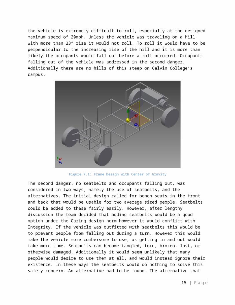
To prevent rollovers the vehicle was tested in Autodesk Inventor do discover the expected center of gravity of the fully loaded vehicle. The vehicle was then modified to adjust the natural center of gravity to be on the lowest part of the frame, centered underneath the front row of seats. This can be seen in Figure 7.1 below. With this design, the vehicle is extremely difficult to roll, especially at the designed maximum speed of 20mph. Unless the vehicle was traveling on a hill with more than 33° rise it would not roll. To roll it would have to be perpendicular to the increasing rise of the hill and it is more than likely the occupants would fall out before a roll occurred. Occupants falling out of the vehicle was addressed in the second danger. Additionally there are no hills of this steep on Calvin College’s campus.
Figure 7.1: Frame Design with Center of Gravity
12 | P a g e

The second danger, no seatbelts and occupants falling out, was considered in two ways, namely the use of seatbelts, and the alternatives. The initial design called for bench seats in the front and back that would be usable for two average sized people. Seatbelts could be added to these fairly easily. However, after lengthy discussion the team decided that adding seatbelts would be a good option under the Caring design norm however it would conflict with Integrity. If the vehicle was outfitted with seatbelts this would be to prevent people from falling out during a turn. However this would make the vehicle more cumbersome to use, as getting in and out would take more time. Seatbelts can become tangled, torn, broken, lost, or otherwise damaged. Additionally it would seem unlikely that many people would desire to use them at all, and would instead ignore their existence. In these ways the seatbelts would do nothing to solve this safety concern. An alternative had to be found. The alternative that the team decided to use is bucket seats. These seats would provide greater resistance to falling out than standard bench seating and thus remove some of the danger in the design. While not alleviating the danger inherent in the design completely, bucket seats do have the advantage that they cannot be ignored or avoided as seatbelts can. They act as a Poka-Yoke built into the design and anyone who sits on them must inevitably take advantage of the seats’ added safety.
The concern of the roof not being a rollover cage came about when it was found that the roof would not be strong enough to protect occupants in a rollover and would instead collapse. However this problem became irrelevant when the first safety concern was addressed, i.e. that there is no way for the vehicle to roll on Calvin’s College’s campus. Additionally the team plans to place stickers on the vehicle denoting the roof’s lack of being a rollover cage.
13 | P a g e
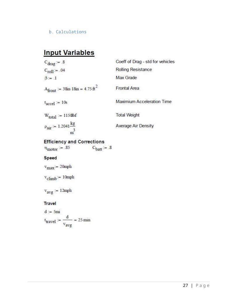
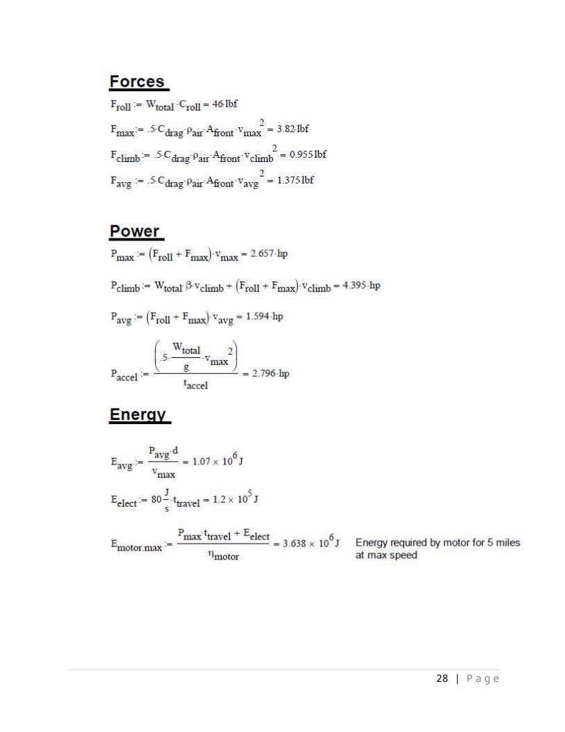
8. Overall Calculations
a. Speed and Power Calculations
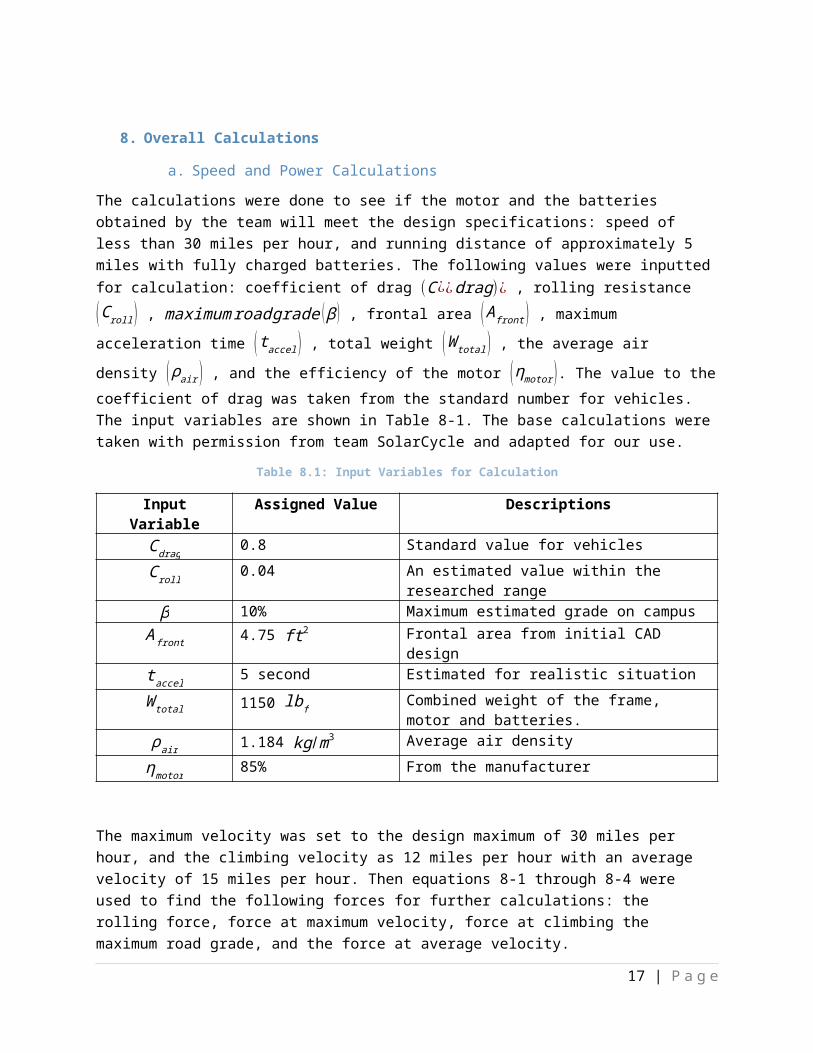
The calculations were done to see if the motor and the batteries obtained by the team will meet the design specifications: speed of less than 30 miles per hour, and running distance of approximately 5 miles with fully charged batteries. The following values were inputted for calculation: coefficient of drag (C ¿¿drag)¿ , rolling resistance (C roll ) , maximumroad grade ( β ) , frontal area ( A front ) , maximum
acceleration time (t accel ) , total weight (W total) , the average air density (ρair) , and the efficiency of the
motor (ηmotor ). The value to the coefficient of drag was taken from the standard number for vehicles. The input variables are shown in Table 8-1. The base calculations were taken with permission from team SolarCycle and adapted for our use.
Table 8.1: Input Variables for Calculation
Input Variable Assigned Value DescriptionsCdrag 0.8 Standard value for vehiclesC roll 0.04 An estimated value within the researched rangeβ 10% Maximum estimated grade on campus
A front 4.75 ft2 Frontal area from initial CAD designt accel 5 second Estimated for realistic situationW total 1150 lbf Combined weight of the frame, motor and
batteries.ρair 1.184 kg /m3 Average air density
ηmotor 85% From the manufacturer
The maximum velocity was set to the design maximum of 30 miles per hour, and the climbing velocity as 12 miles per hour with an average velocity of 15 miles per hour. Then equations 8-1 through 8-4 were used to find the following forces for further calculations: the rolling force, force at maximum velocity, force at climbing the maximum road grade, and the force at average velocity.
F roll=W total ×C roll [Eq 8-1]
Fmax=5×Cdrag× ρair× A front ×vmax2 [Eq 8-2]
Fuphill=5×Cdrag× ρair× A front ×vuphill2 [Eq 8-3]
Favg=5×Cdrag× ρair× A front×vavg2 [Eq 8-4]
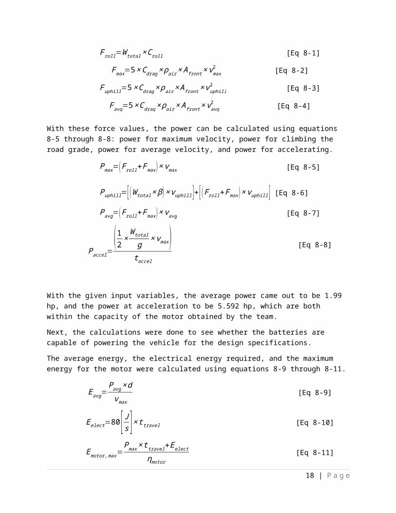
With these force values, the power can be calculated using equations 8-5 through 8-8: power for maximum velocity, power for climbing the road grade, power for average velocity, and power for accelerating.
Pmax=(F roll+Fmax )×vmax [Eq 8-5]
14 | P a g e
Puphill=[ (W total× β )×vuphill ]+[ (F roll+Fmax)×vuphill ] [Eq 8-6]
Pavg=(Froll+Fmax )×vavg [Eq 8-7]
Paccel=( 12×
W total
g×vmax)
t accel
[Eq 8-8]
With the given input variables, the average power came out to be 1.99 hp, and the power at acceleration to be 5.592 hp, which are both within the capacity of the motor obtained by the team.
Next, the calculations were done to see whether the batteries are capable of powering the vehicle for the design specifications.
The average energy, the electrical energy required, and the maximum energy for the motor were calculated using equations 8-9 through 8-11.
Eavg=Pavg×dvmax
[Eq 8-9]
Eelect=80[ Js ]×t travel [Eq 8-10]
Emotor ,max=Pmax×t travel+Eelect
ηmotor[Eq 8-11]
Then the energy contained in batteries at full charge was calculated by using the equations 8-12 and 8-13.
Batt charge=60[A ∙hr ]×3600 [ shr ] [Eq 8-12]
Batt energy=Bat tcharge ×48 [V ] [Eq 8-13]
The energy contained in batteries at full charge, which is1.037×107 [J ], is approximately three times greater than the maximum energy needed to power the motor,2.907×106[J ], which means the batteries will be usable for the vehicle.
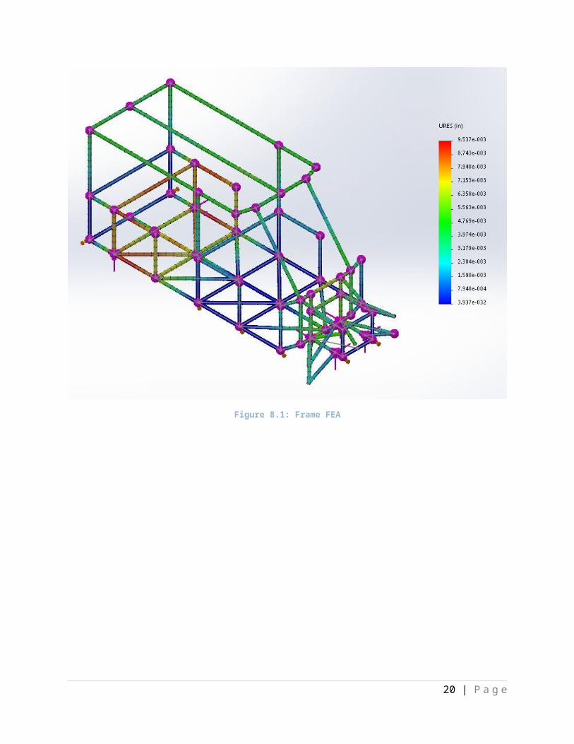
b. Finite Element Analysis
A Finite Element Analysis (FEA) was performed on the Volts-Wagon frame to find the maximum deflection of the frame at critical points. The results of the analysis can be found in Figure 8.1. The total force applied was equal to 1500 lbs and was spread across six different points of the frame to simulate the worst possible case. The worst case loading was having the forces applied to the frame at the connection points of the A-Arms and directly above where the rear axle is located. The total maximum displacement was found to be 9.5 x 10⁻³ in. this amount is acceptable for this vehicle.
15 | P a g e
Figure 8.1: Frame FEA
16 | P a g e
9. Cost Analysis
a. Initial Cost
The team received $500 as its total operating budget for the Senior Design Project. Majority of this money will be spent on buying the metal bars for the frame, since most of the components were already obtained through donation. The operational budget breakdown is shown in Table 9.1 below.
Table 9.1: Initial Budget
DESCRIPTION BUDGETFRAME $150MOTOR $0CONTROLLER $0BATTERIES $0SOLAR PANELS $0CHARGER $0WHEELS & SHOCKS $266STEERING $22HEADLIGHTS/TAILLIGHTS $70MISCELLANEOUS $42TOTAL $550
Other than the price for the charger, the prices are roughly estimated. The donation of components contributed in cutting down the budget by a significant amount.
b. Initial Cost Estimate
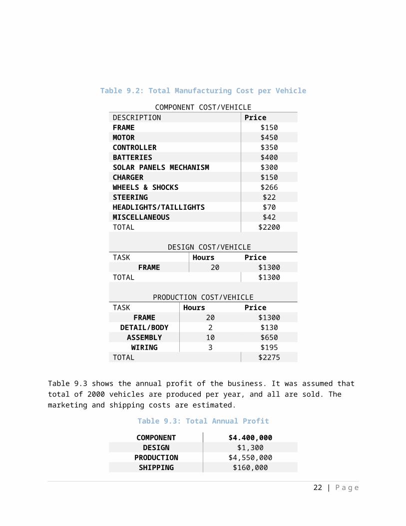
Total cost of manufacturing a vehicle, including the prices of components that are donated and the manufacturing cost, must be considered for large scale production and marketing. It was assumed that total of 5000 vehicles are produced per year, and all are sold.
Table 9.2: Total Manufacturing Cost per Vehicle
COMPONENT COST/VEHICLEDESCRIPTION Price
17 | P a g e
FRAME $150MOTOR $450CONTROLLER $350BATTERIES $400SOLAR PANELS MECHANISM $300CHARGER $150WHEELS & SHOCKS $266STEERING $22HEADLIGHTS/TAILLIGHTS $70MISCELLANEOUS $42TOTAL $2200
DESIGN COST/VEHICLETASK Hours Price
FRAME 20 $1300TOTAL $1300
PRODUCTION COST/VEHICLETASK Hours Price
FRAME 20 $1300DETAIL/BODY 2 $130
ASSEMBLY 10 $650WIRING 3 $195
TOTAL $2275
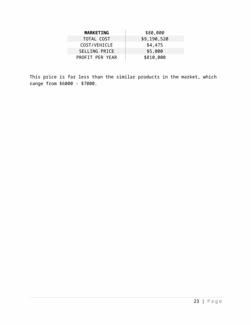
Table 9.3 shows the annual profit of the business. It was assumed that total of 2000 vehicles are produced per year, and all are sold. The marketing and shipping costs are estimated.
Table 9.3: Total Annual Profit
COMPONENT $4.400,000DESIGN $1,300
PRODUCTION $4,550,000SHIPPING $160,000
MARKETING $80,000TOTAL COST $9,190,520
COST/VEHICLE $4,475SELLING PRICE $5,000
PROFIT PER YEAR $810,000
This price is far less than the similar products in the market, which range from $6000 - $7000.
18 | P a g e

10. Conclusion
The team was successful in creating a detailed project design and meeting the specified deadlines. With much discussion, the team has decided to build the prototype from steel tubing with an axel with a differential and electric brushed motor due to budget limitations and conventionality. Most of the components were acquired for free from team SolarCycle.
Based on the performance calculation, a total of 3.638 MJ of energy was found necessary to run the Volts-Wagon at the maximum speed of 20 mph for the required distance of five miles. The batteries available to the team have a usable energy storage capacity of 10.37 MJ. The given batteries should be able to power the vehicle at least double the required distance that was desired.
The design was focused to ensure the operator’s safety as well as user friendliness. The center of gravity of the vehicle was made as low as possible on the vehicle and centered in the frame to prevent rollovers. The vehicle has also be designed to be as comfortable as possible. Given all of these items and the fact the most of the components are already owned, the design has been deemed viable and feasible to the constraints of the Calvin College Engineering 339 course requirements.
Some of the responsibilities the team has yet to complete include: obtaining tubing for frame construction, frame construction, installing electrical components, and assessing the safety and performance of the finished prototype.
19 | P a g e
11. Thank You
There are many thanks from team Volts-Wagon, they are:
- Team SolarCycle from 2013-2014 for donating their project and documentation- Professor Nielsen of Calvin College, the project advisor, for his wise advice- Professor Tubergen of Calvin College for assisting with the design of the frame and FEA- Professor Kim of Calvin College, for his assistance with electrical components- Mr. Phil Jasperse, Calvin College’s mechanics shop manager- Calvin College Engineering Department for funding and support
20 | P a g e

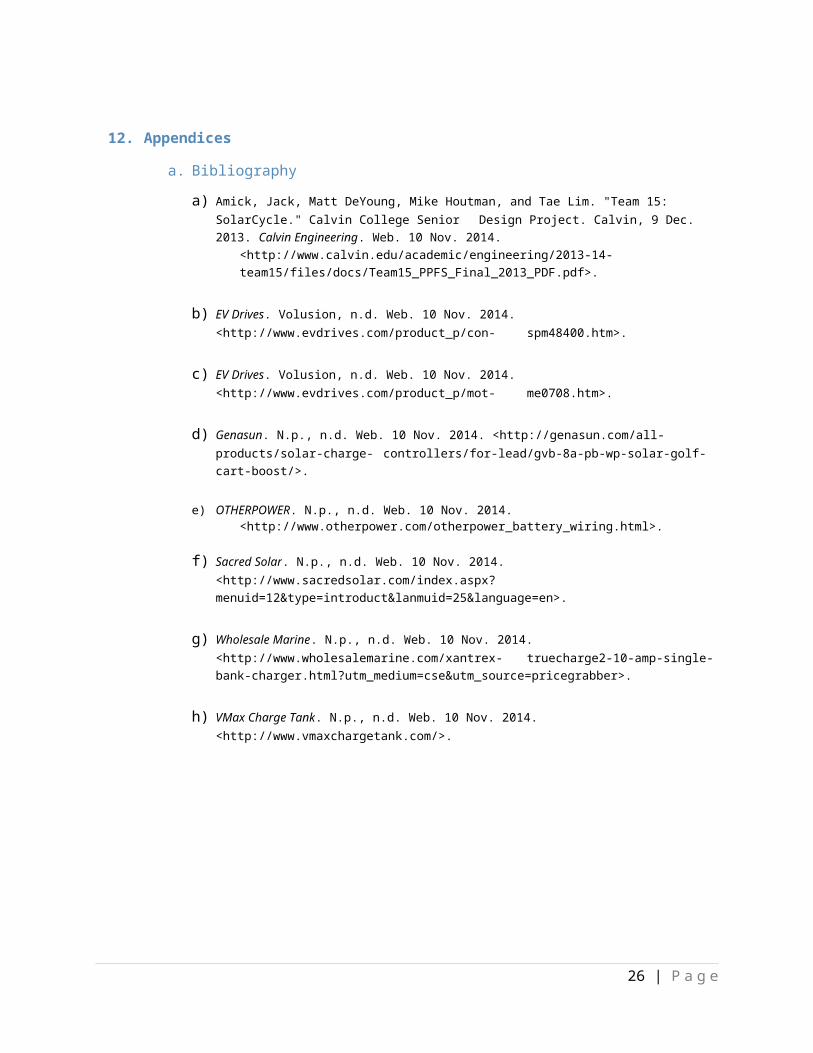
12. Appendices
a. Bibliography
a) Amick, Jack, Matt DeYoung, Mike Houtman, and Tae Lim. "Team 15: SolarCycle." Calvin College SeniorDesign Project. Calvin, 9 Dec. 2013. Calvin Engineering. Web. 10 Nov. 2014.<http://www.calvin.edu/academic/engineering/2013-14-team15/files/docs/Team15_PPFS_Final_2013_PDF.pdf>.
b) EV Drives. Volusion, n.d. Web. 10 Nov. 2014. <http://www.evdrives.com/product_p/con-spm48400.htm>.
c) EV Drives. Volusion, n.d. Web. 10 Nov. 2014. <http://www.evdrives.com/product_p/mot-me0708.htm>.
d) Genasun. N.p., n.d. Web. 10 Nov. 2014. <http://genasun.com/all-products/solar-charge-controllers/for-lead/gvb-8a-pb-wp-solar-golf-cart-boost/>.
e) OTHERPOWER. N.p., n.d. Web. 10 Nov. 2014.<http://www.otherpower.com/otherpower_battery_wiring.html>.
f) Sacred Solar. N.p., n.d. Web. 10 Nov. 2014. <http://www.sacredsolar.com/index.aspx?menuid=12&type=introduct&lanmuid=25&language=en>.
g) Wholesale Marine. N.p., n.d. Web. 10 Nov. 2014. <http://www.wholesalemarine.com/xantrex-truecharge2-10-amp-single-bank-charger.html?utm_medium=cse&utm_source=pricegrabber>.
h) VMax Charge Tank. N.p., n.d. Web. 10 Nov. 2014. <http://www.vmaxchargetank.com/>.
21 | P a g e
b. Calculations
22 | P a g e
23 | P a g e
c. Figures
24 | P a g e
Figure 5.1: Frame Design Modeled in Solidworks
Figure 7.1: Frame Design with Center of Gravity
d. Parts Documentation
i. Motor
25 | P a g e
ii. Motor Controller
26 | P a g e
iii. Charger
27 | P a g e
iv. Electric Schematic
The components used in this project focus around the motor and the turning mechanism. The motor connects to the batteries, which are in series and separated by a fuse in case of overcharge. The motor also connects to the controller at the other end at the V- port. The V+ port connects to the Charger and which also connects to the other side of the batteries. The batteries are connected to a DC-DC converter which is where most of the instrumentation and the presumably where the Auxiliary and communications system will be hooked up. The throttle fuse attaches to the controller at the E/A out ports and the High and Low ends of the throttle attaches at the +VTh and the –Vth ports of the controller.
28 | P a g e