experimental methods for performance and reliability …
TRANSCRIPT

Proceedings of the 1st Global Power and Propulsion Forum GPPF 2017
Jan 16-18, 2017, Zurich, Switzerland www.pps.global
This work is licensed under a Creative Commons Attribution 4.0 International License Creative Commons Attribution-NonCommercial-NoDerivatives 4.0
International License
GPPF-2017-88
EXPERIMENTAL METHODS FOR PERFORMANCE AND RELIABILITY OF STEAM AND GAS TURBINES
Ilias Bosdas [email protected]
Laboratory for Energy Conversion, Department of Mechanical and Process Engineering,
ETH, 8092 Zurich, Switzerland
Michel Mansour [email protected]
Limmat Scientific AG 6300 Zug, Switzerland
Anestis I. Kalfas [email protected]
Department of Mechanical Engineering, Aristotle University of Thessaloniki, 54124
Thessaloniki, Greece
Reza S. Abhari [email protected]
Laboratory for Energy Conversion, Department of Mechanical and Process Engineering,
ETH, 8092 Zurich, Switzerland
ABSTRACT
Nowadays turbomachines are widely used in power
generation, transportation and industry. In order to achieve
high efficiency and reliability, the machines are equipped with
advanced instrumentation to control and monitor their
operation and to evaluate the engineers’ design during the
development phase. The need to achieve even greater
efficiency and flexibility is high, since both steam and gas
turbine designs are driven by the size increase in order to cover
the high energy demand. This paper presents the experimental
methods and instrumentation for the development and
operation of steam and gas turbines. Discussed and surveyed
are the problems encountered, and techniques used, in making
measurements in today's high performance, compact design
turbomachines. Applications of the different techniques in
research and industry are also reviewed together with their
advantages and drawbacks. In addition, the paper presents the
recent developments in instrumentation made in the
Laboratory for Energy Conversion in ETH Zurich in the field
of steam and gas turbines. The paper aims to provide the
essential experimental methods for performance and
reliability measurements in the development and operation
phases.
INTRODUCTION
The progress in turbomachinery the last 50 years is
impressive. The power output of large gas and steam turbines
has reached 600MW and 1.8GW respectively with efficiencies
greater than 60%. In the aviation sector, gas turbines, which
are used to power the aircrafts, can generate up to 115,000lbf
(510kN) thrust, which is translated to 150MW power output
with fuel efficiency as low as 3.1 litres per 100 passenger
kilometres. The outcome is a long-term effort from
researchers in industry and academia with the focus primarily
on improvements in efficiency and performance.
Nevertheless, there is still a margin to improve the efficiency
and increase the performance of these machines. New designs
are driven by the size increase, which creates a greater
challenge in reliability and operational flexibility.
Turbomachinery flows are highly unsteady [1, 2] and
measurements in this complicated flow field environment
require accurate fast response instrumentation. Today, time
resolved measurements are a key element for a successful
development of a steam or/and gas turbine. The high
computational power enables efficient and fast data
processing in four dimensions where the time domain is as
important as the standard three spatial dimensions. Nowadays,
this is possible not only due to the improvements in data
handling but also due to the development of integrated high
accuracy measurement systems where they can be
manufactured with efficient cost. Integration in packaging of
electronics results in high signal to noise ratio and pressure
resolution down to 6Pa on the measured raw signal. This was
not possible when semiconductors were initially used and
therefore today it is an important advantage for every
experimental engineer.
Aerodynamic measurements in steam and gas turbines
Total pressure is one of the most important flow quantities
since it is directly linked to loss and efficiency measurements.
In combination with static pressure, the flow field velocity can

2
be derived and as a consequence the mass flow rate of the
machine can be calculated. Conventional multiple pneumatic
probes are widely used in performance measurements in both
gas and steam turbines [3, 4]. Nevertheless, since
turbomachinery flows are highly unsteady and three
dimensional, fast response aerodynamic probes are more than
necessary when performance measurements are considered.
The development of fast response instrumentation is
strongly related with the progress in the semiconductor
industry. The first fast response probes were developed in the
1980s, however a complete work in the entire measurement
system was presented by Gossweiler in 1993 [5]. Since then
the progress on fast response instrumentation was quite
impressive and the technique was established for performance
measurements in gas turbines [6]. The need for time resolved
measurements in turbomachines has led many researchers to
develop their own fast response aerodynamic probes. In that
regard, Persico et al. [7] developed a fast response
aerodynamic probe using a single commercial pressure sensor.
The sensor is embedded in the probe stem with an outer
diameter of 1.85mm. Shock tube tests have shown a cavity
resonance of 80kHz, however an analytical model to
compensate for the signal amplification and phase shift is
presented by the authors. The probe provides the unsteady
total pressure and yaw angle in the range of ±22deg in the
regions where the flow field is considered to be two-
dimensional and there is no reference on the maximum
temperature where this probe can be operated. A recent
publication by Mersinligil et al. [8] presents the integration
and application of a commercial high temperature and high
bandwidth (up to 250kHz) fast-response flush mounted single
sensor probe. However, due to packaging reasons the diameter
size is 2.5 mm big and the sensor is protected against
mechanical damage from particle impacts only with RTV
coating. As the one of Persico, this probe consists of a single
pressure tap and therefore only 2D flow field measurements
can be obtained. To overcome this issue Lenherr et al.
developed a two sensor fast response high temperature probe
[9]. This is equipped with particle shielded pressure taps,
which protect the pressure sensors from any particle impact
and can be operated up to 260οC. However, this sensor
configuration increases the cavity volume between the
pressure tap and the membrane of the sensor and therefore the
measurement bandwidth is limited to 25kHz uncompensated.
Nevertheless the probe is equipped with two pressure taps one
for yaw and one for pitch angle sensitive and as a result the
probe can provide the unsteady 3D flow field in a miniature
size for high spatial resolution with a probe tip diameter of
2.5mm. The aerodynamic calibration of the probe, under well-
defined flow field conditions, is performed in freejet facility
of the Laboratory for Energy Conversion (LEC) at ETH
Zurich. Typical values are ±30o and ±25o in yaw and pitch
angles respectively up to 0.9 Mach number. The smallest fast
response aerodynamic probe with two sensors for 3D flow
field analysis is developed in LEC lab as well. The probe tip
has a diameter of 1.8mm and the miniature size provides
uncompensated measurement bandwidth up to 48kHz.
For transonic and supersonic flow field conditions,
typically found at the stator exit of the last stage on a low
pressure steam turbines, cylindrical probe geometries become
very sensitive to the Reynolds number. As a consequence,
small variations in the Mach number from the calibrated one
may result in static pressure changes of more than 10%. The
wedge geometry is often chosen since the flow field around it,
is independent of the Reynolds number as described in [3, 10].
A probe for transonic and supersonic measurements in steam
turbines is presented in Figure 1 by Schatz et al. [10]. As
described in the next section of this paper, this probe combines
as well an optical extinction system for wetness measurements
in the last stages of LP steam turbines. The wedge surfaces for
the yaw and pitch angle sensitivity are shown in the same
figure together with the respective total and pitch pressure
taps.
Figure 1: Combined optical and pneumatic probe for transonic measurements in steam turbines by
Schatz et al. [10].
As described previously, fast response instrumentation
for gas turbines has been widely used from many researchers
and today is considered an established technique [6, 9, 11, 12].
However, for the development of steam turbines, experimental
studies of the unsteady aerodynamic excitation of low-
pressure steam blades have been only conducted in down-
scaled air models, as reported in [13]. The literature review in
unsteady flow field measurements reveals the lack of
instrumentation in fast response aerodynamic probes in real
wet steam environment. Most of the researchers have
performed unsteady pressure measurements with flush
mounted pressure sensors on the stator or casing of LP steam
turbines [14, 15]. The challenge in operating flush mounted
sensors is to maintain high robustness from droplet impacts
present in the last stages the machines. Therefore, according
the current literature survey, only one attempt could be found
in the open literature dealing with time-resolved flow field
measurements in the flow path of LP steam turbines. This is
presented by Gerschütz et al. [16] where two different probes
were manufactured, as shown in Figure 2. Both consist of two
pneumatic pressure taps for balancing in flow direction and
one total pressure tap equipped with Kulite® sensor for
unsteady total pressure measurements. The probes can operate
up to 275oC and have a tip diameter of 6mm. The main
drawback of these probes is that they provide the unsteady
pressure fluctuations in a flow region where the flow is
considered again two-dimensional. In addition, the cavity
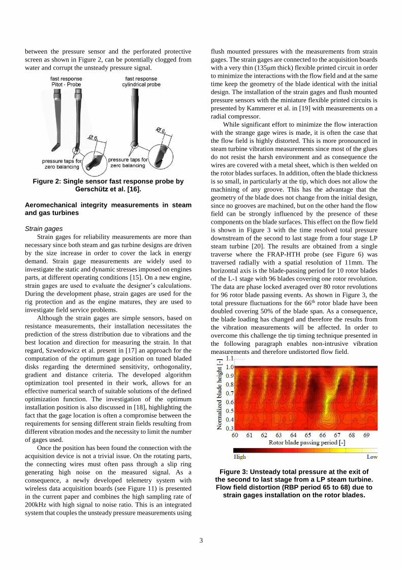
3
between the pressure sensor and the perforated protective
screen as shown in Figure 2, can be potentially clogged from
water and corrupt the unsteady pressure signal.
Figure 2: Single sensor fast response probe by
Gerschütz et al. [16].
Aeromechanical integrity measurements in steam and gas turbines
Strain gages
Strain gages for reliability measurements are more than
necessary since both steam and gas turbine designs are driven
by the size increase in order to cover the lack in energy
demand. Strain gage measurements are widely used to
investigate the static and dynamic stresses imposed on engines
parts, at different operating conditions [15]. On a new engine,
strain gages are used to evaluate the designer’s calculations.
During the development phase, strain gages are used for the
rig protection and as the engine matures, they are used to
investigate field service problems.
Although the strain gages are simple sensors, based on
resistance measurements, their installation necessitates the
prediction of the stress distribution due to vibrations and the
best location and direction for measuring the strain. In that
regard, Szwedowicz et al. present in [17] an approach for the
computation of the optimum gage position on tuned bladed
disks regarding the determined sensitivity, orthogonality,
gradient and distance criteria. The developed algorithm
optimization tool presented in their work, allows for an
effective numerical search of suitable solutions of the defined
optimization function. The investigation of the optimum
installation position is also discussed in [18], highlighting the
fact that the gage location is often a compromise between the
requirements for sensing different strain fields resulting from
different vibration modes and the necessity to limit the number
of gages used.
Once the position has been found the connection with the
acquisition device is not a trivial issue. On the rotating parts,
the connecting wires must often pass through a slip ring
generating high noise on the measured signal. As a
consequence, a newly developed telemetry system with
wireless data acquisition boards (see Figure 11) is presented
in the current paper and combines the high sampling rate of
200kHz with high signal to noise ratio. This is an integrated
system that couples the unsteady pressure measurements using
flush mounted pressures with the measurements from strain
gages. The strain gages are connected to the acquisition boards
with a very thin (135μm thick) flexible printed circuit in order
to minimize the interactions with the flow field and at the same
time keep the geometry of the blade identical with the initial
design. The installation of the strain gages and flush mounted
pressure sensors with the miniature flexible printed circuits is
presented by Kammerer et al. in [19] with measurements on a
radial compressor.
While significant effort to minimize the flow interaction
with the strange gage wires is made, it is often the case that
the flow field is highly distorted. This is more pronounced in
steam turbine vibration measurements since most of the glues
do not resist the harsh environment and as consequence the
wires are covered with a metal sheet, which is then welded on
the rotor blades surfaces. In addition, often the blade thickness
is so small, in particularly at the tip, which does not allow the
machining of any groove. This has the advantage that the
geometry of the blade does not change from the initial design,
since no grooves are machined, but on the other hand the flow
field can be strongly influenced by the presence of these
components on the blade surfaces. This effect on the flow field
is shown in Figure 3 with the time resolved total pressure
downstream of the second to last stage from a four stage LP
steam turbine [20]. The results are obtained from a single
traverse where the FRAP-HTH probe (see Figure 6) was
traversed radially with a spatial resolution of 11mm. The
horizontal axis is the blade-passing period for 10 rotor blades
of the L-1 stage with 96 blades covering one rotor revolution.
The data are phase locked averaged over 80 rotor revolutions
for 96 rotor blade passing events. As shown in Figure 3, the
total pressure fluctuations for the 66th rotor blade have been
doubled covering 50% of the blade span. As a consequence,
the blade loading has changed and therefore the results from
the vibration measurements will be affected. In order to
overcome this challenge the tip timing technique presented in
the following paragraph enables non-intrusive vibration
measurements and therefore undistorted flow field.
Figure 3: Unsteady total pressure at the exit of the second to last stage from a LP steam turbine. Flow field distortion (RBP period 65 to 68) due to
strain gages installation on the rotor blades.

4
Tip timing
Measurements with the tip timing technique are also used
to determine the mechanical vibrations of the rotating blades.
Today, this is a well-established non-intrusive technique,
which allows the analysis of blade fluttering and mistuning up
to a certain eigenfrequencies. The blade tip timing equipment
is typically comprised by a set of sensors (optical, eddy current
or capacitive sensors), which are installed on the casing of the
machine, and they are used to measure the arrival times of
rotating blades. These arrival times, in comparison to the blade
passing frequency, are used to determine the blade deflections
and therefore the vibration characteristics [21]. As presented
in [21] for the purposes of tip timing data analysis, there are
two distinct classes of response, the synchronous and
asynchronous. Synchronous resonances are assembly modes
that are excited at multiples of the rotational speed.
Asynchronous resonances are mainly due to aerodynamic
instabilities such as rotating stall and flutter.
Particle and droplet measurements with optical probes
Measurement techniques using optical methods have a
wide application in performance as well as reliability for gas
and steam turbines. In the aviation sector, the recent volcanic
eruption in Iceland in 2010 brought a special attention to the
topic due to the unclear safety margins that the engines could
be operated. Atmospheric ice and subcooled water ingestion
due to severe weather conditions have as well negative effects
on the aircrafts’ engines performance and reliability. On the
other hand, the erosion phenomena in the last stages of LP
steam turbines are still under investigation and the accelerated
erosion rate, of the last rotor driven by the size increase, is a
major challenge. In turbomachinery, measurement techniques
for particle-laden flows are mainly focused on liquid droplet
measurements. They are distinguished between fog droplet
measurements with droplet diameters from 0.1 to 10μm and
coarse droplet measurements with diameters from 10μm and
above [22, 23].
Fog water droplet measurements for steam turbine applications
Regarding droplet measurements for turbomachinery
applications, there is a significant number of publications
dealing with the development of different probes to measure
droplets’ size and concentration. The most promising
technique for measuring these small droplets in the submicron
range is the optical extinction method as described by the
Beer-Lambert law. This principle is utilized in the well known
optical extinction probes, which are used in steam turbines
since 1970s with some of the first attempts made by Walters
et al. [24] and Young et al. [25]. However, the probe tip
diameters are relatively large (dia. 20mm) and a consequence
the interaction with the flow field can be considered high.
According to the literature review the smallest optical
extinction probe was build by Schatz et al. as presented in [10]
and shown in Figure 1. This probe has a tip diameter of 10mm
and combines an optical and pneumatic part for the time
averaged flow field measurements with the nulling technique.
Since the probe surfaces are prone to water contamination
many times these probes are heated to improve the accuracy
of the results. A probe for the same flow field environment
capable to measure transonic flow velocities and fog droplets
in one system was developed by Wu et al. [26] and shown in
Figure 4. As presented in the same figure the difference of this
probe from the one of reference [10] is the position of the
pneumatic part relative to the optical part. The wedge surfaces
with the pressure taps are placed 50mm away from the optical
path affecting the spatial resolution of the measurements.
Figure 4: The tip from a combined optical and
pneumatic probe by Wu et al. [26].
Coarse water droplet measurements for steam turbine applications
As it has been described so far, the majority of the
developed probes for steam turbine applications have a
minimum tip diameter of 10mm and a detectable droplet size
up to 10μm, mainly implementing time averaging techniques
such as light extinction. These probes are suitable for fog
droplet measurements and therefore erosion phenomena
cannot be fully studied. Cai et al. in [27] have developed an
integrated probe system for coarse water droplet
measurements up to 400μm. As shown in Figure 5, the system
consists of a fine droplet measurement subsystem using the
light extinction technique and a coarse droplet measurement
subsystem using the forward light scattering technique. The
probe has a tip diameter of 20mm and it incorporates as well
a pneumatic part for the time averaged flow field
measurements. In their results at the last stage of a steam
turbine, the authors present the droplet trajectories and speeds
under various operating conditions. A noteworthy work from
the same research group for coarse droplet measurements is
by Xueliang et al. [28]. In this report, the authors present a
video-probe system capable to take images of coarse water
droplets (Dp>10μm), in order to measure the diameter and
velocity. The probe is calibrated using standard
monodispersed glass beads up to 77.2μm in diameter, as well
as in a spray environment with a known concentration and
diameter. The main drawbacks of the last two approaches are
the relative big size of the probe tips (Dp>20mm) affecting the
spatial resolution of the measurements and the low
measurement bandwidth on the aerodynamic part constraining
the results to a time averaged flow field analysis.

5
Figure 5: Photograph of the combined optical
and pneumatic probe by Cai et al. [27].
RECENT DEVELOPMENTS
Pressure measurements
Probe technology
Time resolved measurements in the biphasic regime of
steam turbines are very challenging, due to the harsh
environment of fog and coarse water droplets. The droplets’
range is from 0.1 up to 200μm or even 400 μm in diameter and
when the probe is inserted into the flow path droplets can
potentially clog the pressure taps or even damage the
miniature piezoresistive pressure sensors when they are
exposed. A recent development of a fast response
aerodynamic probe for unsteady measurements in wet steam
is presented in [29, 30]. The design and operation of this probe
is based on the previous developments made over the last 25
years in the Laboratory of Energy Conversion. Similarly to the
probe developed by Lenherr et al. [9], the FRAP-HTH probe
(see Figure 6) has two piezo-resistive sensors encapsulated
into a probe tip diameter of 2.5mm which can be operated up
to a temperature of 260oC. The new feature of this probe is a
miniature cartridge heater, which increases the probe tip
temperature 5 to 10oC above the flow saturation temperature,
in order to operate the probe with unclogged pressure taps. In
addition, the two pressure taps are equipped with a metal
shield for protecting the miniature piezoresistive sensors from
direct water droplet impacts.
Figure 6: The fast response aerodynamic probe
(FRAP-HTH) with the miniature heater for unsteady flow field measurements in wet steam
[29].
Figure 7.a and b shows the absolute yaw angle and Mach
number results respectively with the FRAP-HTH probe from
a single traverse downstream of the last stage from a 1/2.2
scale steam turbine. For this operating condition the mass
flow, inlet temperature and exit pressure are 67t/h, 266oC and
8kPa respectively considered as a high load operating point.
The calculated wetness mass fraction in the meridional plan is
8%. It is interesting to notice the flow underturing at 50% span
in Figure 7.a, due to the presence of the part span connector
installed on the last rotor. The effect of part span connector is
also depicted in the absolute Mach number at 50% blade span
with a deficit in the flow velocity. The peak-to-peak
fluctuations are large at the tip region for both flow quantities
and they are progressively reduced towards the hub. The peak-
peak to fluctuations at 90% span are ±6 deg and ±0.11 for the
yaw angle and absolute Mach number respectively.
(a)
(b)
Figure 7: Absolute flow yaw angle (a) and Mach number at the rotor exit of L-0 stage from a four
stage LP steam turbine.
Figure 8 shows the unsteady total pressure fluctuations
from a single traverse at the rotor exit of the last stage with the
same operating conditions as described in the previous
paragraph. The results are non-dimensionalized with the time
average total pressure and they are plotted for one rotor
revolution (70 rotor blades) from hub to tip.
Figure 8: Unsteady total pressure Ptot/Ptotavg from a single traverse at the exit of a LP steam
turbine. The radial axis is the blade span and the azimuthal axis is the blade count over one rotor
revolution.
miniature heater
dim. in mm

6
As presented in Figure 7.a and b the same trend is observed
for the total pressure in Figure 8 with the peak-peak
fluctuations getting the maximum value at the blade tip and
progressively being reduced to the hub.
Flush mounted sensor technology
The need to measure the unsteady pressure fluctuations
on the surface of the stators or rotating blades requires flush
mounted pressure transducers smaller than 1mm in order to fit
in the very thin blade profiles. Besides the miniature size the
challenges of robustness and high signal to noise ratio are as
of a great importance. As shown in Figure 9, the pressure
sensor developed by Mansour et al. [31] utilizes one of the
smallest absolute piezoresistive sensors available in the
market with cross section dimensions of 300 x 180μm and a
length of 0.9mm, which makes it particularly prone for
achieving a small packaged assembly with high measurement
bandwidth up to 210kHz without the perforated protection
screen [31]. As shown in Figure 9 and Figure 10, in the second
version of this surface mount pressure sensor, the same piezo-
resistive pressure chip is packaged under a perforated
protective screen with a thickness of 0.05mm which contents
11 pressure holes. This design offers greater protection from
particle impacts with a measurement bandwidth at 55kHz. The
overall dimensions of this pressure sensor are 1.75mm x
0.81mm x 0.52mm. The sensor is connected to the acquisition
system through a flexible printed circuit of 0.135mm in
thickness, reducing its interaction with the flow boundary
layer of the installed surface (stator or rotor).
Figure 9: Surface mounted pressure sensor.
The packaging and bonding techniques that were used
ensure optimal spatial resolution, measurement bandwidth and
protection in harsh conditions. Moreover the present design
provides a high degree of reliability and low levels of thermal
disturbance to the sensors as the flow can experience large
temperature and pressure fluctuations.
Figure 10: Surface mounted pressure sensor
[31].
Multi-sensor Wireless data acquisition board
The sensors’ voltage signals are acquired using an in-
house developed wireless data acquisition system boards as
presented in Figure 11. The wireless measurement system
consists of a fast and high resolution A/D recorder and a
logger. They are designed to operate in the rotating frame of
reference up to steady accelerations of 15’000 g.
Figure 11: Wireless data acquisition boards
installed on the rotor disc.
Each board has 4 analogue input channels synchronized
from a single optical signal, and the boards can be stacked up
to 4 boards offering 16 simultaneous analogue voltage
acquisition channels. Each of board can acquire either 2 piezo-
resistive pressure sensors, 4 strain gages or Pt100 operated in a
constant current mode. The boards have a diameter and a
height of 65mm and 9mm, respectively. The fast-pressure
sensors are operated with a constant current of 1mA through
individual programmable current sources. The boards are
specifically design to acquire dynamic signals up to a
sampling frequency of 200kHz. The data are temporarily
stored on an on-board mini solid state disk, before being sent
to an external computer through an embedded Wi-Fi module.
Each acquisition channel is equipped with a dedicated
signal conditioning modules with a tunable gain ranging from
1 to 128. For the current application a gain of 128 is used,
resulting in a peak-to-peak white noise RMS value of 160 V
setting the minimum pressure resolution of approximately 6pa
on the measured raw signal; providing a measurement
resolution which is an order of magnitude higher than the
sensor measurement accuracy.
dim. in mm
On-board
electronics
with 6
boards
Wire
connections
to the
blades
Sensitive
area
7
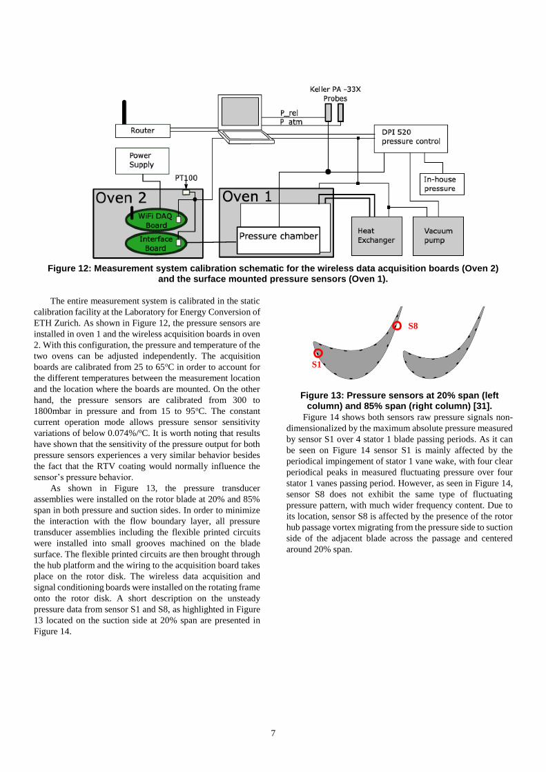
Figure 12: Measurement system calibration schematic for the wireless data acquisition boards (Oven 2)
and the surface mounted pressure sensors (Oven 1).
The entire measurement system is calibrated in the static
calibration facility at the Laboratory for Energy Conversion of
ETH Zurich. As shown in Figure 12, the pressure sensors are
installed in oven 1 and the wireless acquisition boards in oven
2. With this configuration, the pressure and temperature of the
two ovens can be adjusted independently. The acquisition
boards are calibrated from 25 to 65oC in order to account for
the different temperatures between the measurement location
and the location where the boards are mounted. On the other
hand, the pressure sensors are calibrated from 300 to
1800mbar in pressure and from 15 to 95oC. The constant
current operation mode allows pressure sensor sensitivity
variations of below 0.074%/oC. It is worth noting that results
have shown that the sensitivity of the pressure output for both
pressure sensors experiences a very similar behavior besides
the fact that the RTV coating would normally influence the
sensor’s pressure behavior.
As shown in Figure 13, the pressure transducer
assemblies were installed on the rotor blade at 20% and 85%
span in both pressure and suction sides. In order to minimize
the interaction with the flow boundary layer, all pressure
transducer assemblies including the flexible printed circuits
were installed into small grooves machined on the blade
surface. The flexible printed circuits are then brought through
the hub platform and the wiring to the acquisition board takes
place on the rotor disk. The wireless data acquisition and
signal conditioning boards were installed on the rotating frame
onto the rotor disk. A short description on the unsteady
pressure data from sensor S1 and S8, as highlighted in Figure
13 located on the suction side at 20% span are presented in
Figure 14.
Figure 13: Pressure sensors at 20% span (left column) and 85% span (right column) [31].
Figure 14 shows both sensors raw pressure signals non-
dimensionalized by the maximum absolute pressure measured
by sensor S1 over 4 stator 1 blade passing periods. As it can
be seen on Figure 14 sensor S1 is mainly affected by the
periodical impingement of stator 1 vane wake, with four clear
periodical peaks in measured fluctuating pressure over four
stator 1 vanes passing period. However, as seen in Figure 14,
sensor S8 does not exhibit the same type of fluctuating
pressure pattern, with much wider frequency content. Due to
its location, sensor S8 is affected by the presence of the rotor
hub passage vortex migrating from the pressure side to suction
side of the adjacent blade across the passage and centered
around 20% span.
S1
S8

8
Figure 14: Pressure fluctuation of Sensor S1 and
Sensor S8 located on the suction side at 20% span over four stator 1 vane passing periods
[31].
Optical extinction measurements
The knowledge of droplet size distribution and
concentration allows us to calculate the wetness fraction and
the isentropic turbine efficiency as well as to provide
significant data for erosion modeling. For that purpose, a
miniature optical extinction probe with a diameter of 9.4mm
was designed, manufactured and tested in LEC lab. Although
this is a well-known measurement technique this new
development is equipped with a heater, which maintains all
optical components of the probe clean from any water
contamination and therefore the accuracy of the results is
improved. The probe tip is presented in Figure 15.
Figure 15: The optical extinction probe tip
In order to test the performance of the heater, the probe
was tested under representative steam flow conditions in a
freejet facility as well as in a steam generator. The flow
conditions are Nusselt number representative of the last stage
of a low-pressure steam turbine with 0.35 Mach number, 44oC
flow tempearature and static pressure of around 8kPa. Three
different conditions were tested were the Nusselt number was
varied with the maximum value of Nu=108 when the wetness
fraction of 10% was used in the calculations. During these
measurements two thermocouples were installed on the probe
tip, one on the center of the collimating lens and one on the
center of the mirror. As shown in Figure 16, a minimum
temperature overheat of 20oC is achieved in all test cases for
both the mirror as well as the lens. The mirror though shows a
lower overheat temperature of about 50% compared to the
collimating lens for all test cases. This is explained by the
lower power density (60% reduced), which is installed in the
upper part of the probe tip compared to the lower part where
the lens is installed.
An ultrasonic atomizer was characterized in terms of
droplet size and concentration with an established Phase
Doppler Anemometry (PDA) system in order to have a
reference spray environment for the proof of concept of the
newly developed optical extinction probe. Measurements
were performed and results have shown a good agreement
between the PDA technique and the extinction probe at
various axial locations from the nozzle exit of the droplet
generator. The maximum deviation is less than 2.5μm and
1.2μm for the Sauter mean (D32) and most frequent diameter
respectively.
Figure 16: Heater performance tests at three representative flow conditions from the last
stage of a low pressure steam turbine.
In order to extend the knowledge of the droplet in the
coarse diameters range, an optical backscatter probe for coarse
water droplet measurements was developed by Bosdas et al.
and presented in [32]. This probe has an embedded high
bandwidth miniature photodiode capable of measuring
particle speeds up to 200m/s. The probe tip is 5.5mm in
diameter and the probe was used for droplet measurements
with diameters from 40 up to 110 μm. As shown in Figure 17,
light is guided in the probe tip through an optical fiber and
then it is focused three probe diameters far from the tip
forming the measurement sample volume. For this purpose a
monochromatic (λ=632nm) He-Ne laser is used. When the
droplets cross the focused sample volume, they scatter light in
all directions, but the installed photodiode captures the scatter
light at specific backscatter solid angle through a set of
collective lenses. In addition, the probe tip is equipped with a
purging system in order to maintain the windows clean from
water and avoid any beam deflection. The purging flow is
attached to the surface of the windows in order to minimize
any interaction with the surrounding flow field.
dim. in mm

9
Figure 17: FRAP-OB probe tip with purging
interface for windows protection [32].
The FRAP-OB is calibrated in a monodispersed
calibration facility described in [32]. The probe calibration is
performed using an in-house droplet generator.
Monodispersed droplet generation in the kHz range is based
on the Rayleigh breakup jet. For the current work the device
was tuned to produce monodispersed water droplets with an
accuracy of ±2μm in diameter that are generated continuously
with a frequency and air-backpressure set by the user. For
independent reference measurements of the droplet size the
shadow imaging technique was utilized. The droplets are
imaged with a high-resolution camera that is triggered with a
strobe light in order to capture images of the generated
droplets. For the maximum amplification factor the accuracy
of this technique results in an error of ±0.69μm in diameter.
The calibration of FRAP-OB probe is completed when the
probe’s output voltage signal is correlated with the measured
droplets’ diameter from the pictures obtained with the
reference camera. As shown in Figure 18, the calibration curve
is modeled by an exponential curve fit. The uncertainty
analysis presented in [32] has shown an accuracy of ±5.4μm
and 2.3m/s for the diameter and speed measurements
respectively for the overall system.
Figure 18: FRAP-OB calibration curve using a monodispersed water droplet generator [32].
CONCLUSIONS
Today, the measurement system integration enables
accurate time resolved measurements, which are the
key element for a successful development of a
turbomachine. The high volume of the recorded data
can be processed fast and efficiently due to great
computational power and this contributes to the
analysis of the complicated four dimensional flow field
in steam and gas turbines.
For the fast response aerodynamic probe a compromise
between miniaturization, robustness, bandwidth and
the capability of the probe to measure the three-
dimensional flow field has to be made. The best
compromise is found with a two sensor probe with a tip
diameter at 1.8mm and a measurement bandwidth of
48kHz. For high temperature applications up to 250oC
the probe tip diameter is 2.5mm providing a
measurement bandwidth of 25kHz.
Unsteady flow field measurements in wet steam are
even more challenging due to the presence of coarse
water droplets in the biphasic regime of LP steam
turbines. In addition, the high flare angles of the
machines necessitate only probes capable to measure
the three-dimensional flow field due to the high
(>40deg) flow pitch angles. Flush mounted sensors are
prone to droplet impacts, thus the newly developed
heated probe tip with encapsulated sensors is the most
appropriate approach to provide high accuracy and
robustness.
Strain gage measurements are required for vibration
analysis however there is always a challenge when
transmitting the signals either with slip rings or
telemetry systems. The newly developed system, with
on-board electronics presented in the current paper,
offers an improved measurement resolution thanks to a
high signal to noise ratio and combines the
aeromechanical assessment of rotating blades with
flush mounted pressure sensors and strain gages.
Droplet measurements in steam turbines require probes
capable to resolve diameters from 0.1 up 400μm. A
compromise between miniaturization and detectable
range has to be made. Combined optical probes are
normally large (dia. 20mm) relative to the flow
feautures resulting in low spatial resolution and high
blockage effects in the downscaled steam turbine test
rigs. A novel miniature fast response optical
backscatter probe was presented in the current paper
and calibrated for droplets from 40 to 110μm in
diameter with the possibility to extend the measurable
range. The same backscatter technique can be used for
solid particles as well.
ACKNOWLEDGMENTS
The authors would like to thank Flori Alickaj, Rolf
Rüttimann and Thomas Künzle for the technical support over
the last 6 years during the development of the FRAP probes.
In addition, the authors acknowledge the help of Patrick
Rebholz for providing the unsteady flush mounted pressure
data. Finally, special thanks go to Dr. Shigeki Senoo from
Mitsubishi Hitachi Power Systems for his support during the
measurements with the FRAP-HTH and FRAP-OB probes in
the steam turbine test facility in Japan.
dim. in mm
10
REFERENCES [1] Ainsworth, R. W., Allen, J. L., and Batt, J. J. M., 1995,
"The Development of Fast Response Aerodynamic Probes
for Flow Measurements in Turbomachinery," Journal of
Turbomachinery, 117(4), pp. 625-634.
[2] Miller, R. J., Moss, R. W., Ainsworth, R. W., and
Horwood, C. K., 2003, "Time-Resolved Vane-Rotor
Interaction in a High-Pressure Turbine Stage," Journal of
Turbomachinery, 125(1), pp. 1-13.
[3] Sieverding, C. H., Arts, T., Dénos, R., and Brouckaert, J.
F., 2000, "Measurement techniques for unsteady flows in
turbomachines," Experiments in Fluids, 28(4), pp. 285-
321.
[4] Völker, L., Casey, M., Dunham, J., and Stüer, H., 2008,
"The Influence of Lean and Sweep in a Low Pressure
Steam Turbine: Throughflow Modelling and Experimental
Measurements," ASME, Berlin, Vol. 6: Turbomachinery,
Parts A, B, and C, GT2008-50161.
[5] Gossweiler, C., 1993,"Sonden und Messsystem für
Schnelle Aerodynamische Strömungsmessung mit
piezoresistiven Druckgebern," Diss. ETH, Nr. 10253.
[6] Kupferschmied, P., Köppel, P., Roduner, C., and
Gyarmathy, G., 2000, "On the Development and
Application of The FRAP (Fast-Response Aerodynamic
Probe) System for Turbomachines - Part 1: The
Measurement System," Journal of Turbomachinery,
122(3), pp. 505-516.
[7] Persico, G., Gaetani, P., and Guardone, A., 2005, "Design
and analysis of new concept fast-response pressure
probes," Measurement Science and Technology, 16(9), pp.
1741-1750.
[8] Mersinligil, M., Brouckaert, J.-F., Courtiade, N., and
Ottavy, X., 2012, "A High Temperature High Bandwidth
Fast Response Total Pressure Probe for Measurements in a
Multistage Axial Compressor," Journal of Engineering for
Gas Turbines and Power, 134(6), pp. 061601-061601.
[9] Lenherr, C., Kalfas, A. I., and Abhari, R. S., 2010, "High
Temperature Fast Response Aerodynamic Probe," Journal
of Engineering for Gas Turbines and Power, 133(1), pp.
011603-011613.
[10] Schatz, M. and Casey, M., 2007, "Design and testing of a
new miniature combined optical/pneumatic wedge probe
for the measurement of steam wetness," AIP Conference
Proceedings, 914(1), pp. 464-479.
[11] Hodson, H. and Dambach, R., 1998, "Single-sensor fast
response pressure probes - the “least-squares” method of
data reduction," 14th Symp on Measuring Techniques in
Transonic and Supersonic Flow in Cascades and
Turbomachines, Limerick
[12] Michel, M., Ndaona, C., Anestis, I. K., and Reza, S. A.,
2008, "Time-resolved entropy measurements using a fast
response entropy probe," Measurement Science and
Technology, 19(11), p. 115401.
[13] Megerle, B., Stephen Rice, T., McBean, I., and Ott, P.,
2012, "Numerical and Experimental Investigation of the
Aerodynamic Excitation of a Model Low-Pressure Steam
Turbine Stage Operating Under Low Volume Flow,"
Journal of Engineering for Gas Turbines and Power,
135(1), p. 012602.
[14] Segawa, K., Senoo, S., Kudo, T., Nakamura, T., and
Shibashita, N., 2012, "Steady and Unsteady Flow
Measurements Under Low Load Conditions in a Low
Pressure Model Steam Turbine," ASME, Anaheim,
California, Vol. 3: Thermal-Hydraulics; Turbines,
Generators, and Auxiliaries, ICONE20-POWER2012-
54862.
[15] Shibukawa, N., Iwasaki, Y., Takada, Y., Murakami, I.,
Suzuki, T., and Fukushima, T., 2014, "An Experimental
Investigation of the Influence of Flash-Back Flow on Last
Three Stages of Low Pressure Steam Turbines," ASME,
Düsseldorf, Vol. 1B, GT2014-26897.
[16] Gerschütz, W., Casey, M., and Truckenmüller, F., 2005,
"Experimental investigations of rotating flow instabilities
in the last stage of a low-pressure model steam turbine
during windage," Proceedings of the Institution of
Mechanical Engineers, Part A: Journal of Power and
Energy, 219(6), pp. 499-510.
[17] Szwedowicz, J., Senn, S. M., and Abhari, R. S., 2002,
"Optimum Strain Gage Application to Bladed
Assemblies," Journal of Turbomachinery, 124(4), pp. 606-
613.
[18] Sensmeier, M. and Nichol, K., "Optimum placement of
sensors for vibration measurements on turbine engine
blades," in 39th AIAA Structures, Structural Dynamics,
and Materials Conference and Exhibit, ed: American
Institute of Aeronautics and Astronautics, 1998.
[19] Kammerer, A. and Abhari, R. S., 2010, "The Cumulative
Effects of Forcing Function, Damping, and Mistuning on
Blade Forced Response in a High Speed Centrifugal
Compressor With Inlet Distortion," Journal of Engineering
for Gas Turbines and Power, 132(12), pp. 122505-122505.
[20] Duan, C., Ishibashi, K., Senoo, S., Bosdas, I., Mansour, M.,
Kalfas, A., et al., "Unsteady Wet Steam Flow
Measurements in a Low-Pressure Test Steam Turbine,"
presented at the 13th Asian International Conference on
Fluid Machinery, Tokyo Japan, September 2015
[21] Heath, S. and Imregun, M., 1998, "A Survey of Blade Tip-
Timing Measurement Techniques for Turbomachinery
Vibration," Journal of Engineering for Gas Turbines and
Power, 120(4), pp. 784-791.
[22] Moore, M. J. and Sieverding, C. H., Two-phase steam flow
in turbines and separators : theory - instrumentation -
engineering: Washington & London: Hemisphere New
York a.o.: McGraw-Hill, 1976.
[23] Kleitz, A. and Dorey, J. M., 2004, "Instrumentation for wet
steam," Proceedings of the Institution of Mechanical
Engineers, Part C: Journal of Mechanical Engineering
Science, 218(8), pp. 811-842.
[24] Walters, P. and Skingley, P., 1979, "An optical instrument
for measuring the wetness fraction and droplet size of wet
steam flows in LP turbines," Proc. Inst. Mech. Eng., Part
C, 141(79), pp. 337-348.
[25] Young, J. B., Yau, K. K., and Walters, P. T., 1988, "Fog
Droplet Deposition and Coarse Water Formation in Low-
Pressure Steam Turbines: A Combined Experimental and
Theoretical Analysis," Journal of Turbomachinery, 110(2),
pp. 163-172.
[26] Wu, G., Song, Y., Ning, T., Su, M., Li, J., Niu, F., et al.,
2010, "Investigation of wet steam flow in a 300 MW direct
air-cooling steam turbine. Part 2: flow field and windage,"
Proceedings of the Institution of Mechanical Engineers,
Part A: Journal of Power and Energy, 224(1), pp. 129-137.
[27] Cai, X., Ning, D., Yu, J., Li, J., Ma, L., Tian, C., et al.,
2014, "Coarse water in low-pressure steam turbines,"
Proceedings of the Institution of Mechanical Engineers,
Part A: Journal of Power and Energy, 228(2), pp. 153-167.
[28] Fan, X., Jia, Z., Zhang, J., and Cai, X., 2009, "A video
probe measurement system for coarse water droplets in LP
steam turbine," Journal of Physics: Conference Series,
147(1), p. 012065.
[29] Bosdas, I., Mansour, M., Kalfas, A. I., Abhari, R. S., and
Senoo, S., 2015, "Unsteady Wet Steam Flow Field
Measurements in the Last Stage of Low Pressure Steam

11
Turbine," Journal of Engineering for Gas Turbines and
Power, 138(3), pp. 032601-032601.
[30] Bosdas, I., Mansour, M., Kalfas, A., Abhari, R., and Senoo,
S., "Unsteady Flow Field and Coarse Droplet
Measurements in the Last Stage of a Low Pressure Steam
Turbine with Supersonic Airfoils Near the Blade Tip,"
presented at the IGTI, Seoul, 2016, Vol. GT2016-57753
[31] Mansour, M., Rebholz, P., Kalfas, A. I., and Abhari, R. S.,
2015, "An On-Board Wireless Multisensor Measurement
System for Rotating Turbomachinery Application," IGTC,
Tokyo, Japan
[32] Bosdas, I., Mansour, M., Kalfas, A. I., and Abhari, R. S.,
2016, "An optical backscatter probe for time resolved
droplet measurements in turbomachines," Measurement
Science and Technology, 27(1), p. 015204.