exploiting setup–hold-time interdependence in …emre/papers/04167994.pdfexploiting...
TRANSCRIPT

1114 IEEE TRANSACTIONS ON COMPUTER-AIDED DESIGN OF INTEGRATED CIRCUITS AND SYSTEMS, VOL. 26, NO. 6, JUNE 2007
Exploiting Setup–Hold-Time Interdependence inStatic Timing Analysis
Emre Salman, Student Member, IEEE, Ali Dasdan, Member, IEEE, Feroze Taraporevala, Member, IEEE,Kayhan Küçükçakar, Member, IEEE, and Eby G. Friedman, Fellow, IEEE
Abstract—A methodology is proposed to exploit the interdepen-dence between setup- and hold-time constraints in static timinganalysis (STA). The methodology consists of two phases. The firstphase includes the interdependent characterization of sequentialcells, resulting in multiple constraint pairs. The second phaseincludes an efficient algorithm that exploits these multiple pairs inSTA. The methodology improves accuracy by removing optimismand reducing unnecessary pessimism. Furthermore, the tradeoffbetween setup and hold times is exploited to significantly reducetiming violations in STA. These benefits are validated using in-dustrial circuits and tools, exhibiting up to 53% reduction in thenumber of constraint violations as well as up to 48% reduction inthe worst negative slack, which corresponds to a 15% decrease inthe clock period.
Index Terms—Constraint characterization, hold time, librarycharacterization, setup–hold interdependence, setup time, statictiming analysis (STA), timing constraint, timing violation.
I. INTRODUCTION
THE CONTINUOUS scaling of complementary metal–oxide–semiconductor technology supports higher speed
very large scale integration (VLSI) circuits. Operating fre-quencies of up to 1 GHz are common in modern deep-submicrometer application-specific integrated circuits. As thesystem clock period decreases, the pessimism imposed bytiming verification tools becomes less acceptable. More ac-curate characterization and verification techniques are there-fore highly desirable.
The timing verification of VLSI circuits is achieved by meansof static timing analysis (STA) tools. The STA tools rely ondata described in the cell libraries to analyze the circuit. Thecharacterization of the individual cells in cell libraries is there-fore highly critical in terms of the accuracy of the STA results[1]–[4]. Specifically, the setup- and hold-time constraints of thesequential cells are used to verify the timing of a synchronouscircuit. Inaccurate characterization of timing constraints causesthe STA results to be either highly optimistic or pessimistic.Both cases should be avoided as the optimistic case can cause a
Manuscript received March 17, 2006; revised July 14, 2006. This paper wasrecommended by Associate Editor C. J. Alpert.
E. Salman and E. G. Friedman are with the Department of Electrical andComputer Engineering, University of Rochester, Rochester, NY 14627 USA(e-mail: [email protected]; [email protected]).
A. Dasdan was with Synopsys, Inc., Mountain View, CA 94043 USA. He isnow with Yahoo, Inc., Santa Clara, CA 95054 USA (e-mail: [email protected]).
F. Taraporevala and K. Küçükçakar are with Synopsys, Inc., Mountain View,CA 94043 USA (e-mail: [email protected]; [email protected]).
Digital Object Identifier 10.1109/TCAD.2006.885834
fabricated circuit to fail, whereas the pessimistic case unneces-sarily degrades circuit speed.
The overoptimism or pessimism in STA is primarily due tothe “independent” characterization of the timing constraints,although these constraints (including CLK-to-Q delay) are“interdependent.” The constraints should therefore be charac-terized interdependently to remove optimism or pessimism inSTA. In [5], a timing-constraint characterization that minimizesthe sum of the CLK-to-Q delay and the setup time is proposed.In [6], the CLK-to-Q delay of a sequential cell is modeled, con-sidering the dependence between the CLK-to-Q delay and thesetup time. A 50–60-ps decrease in the clock period is shown ifthis dependence is considered during STA. These approaches,however, do not consider the interdependence between thesetup time and the hold time. An approach for interdependentcharacterization is proposed in [7], and a solution that con-siders the dependence between the setup time, hold time, andCLK-to-Q delay is offered in [8] to determine the maximumoperating frequency of a sequential cell. These approaches,however, do not exploit the interdependence in STA.
When the interdependence is considered during constraintcharacterization of a sequential cell, multiple valid constraintpairs, which are interchangeable, are obtained. These multiplepairs can be utilized in STA to significantly reduce timingviolations and improve negative slack. Multiple constraintpairs, however, are currently not exploited.
A comprehensive methodology is proposed in this paper torectify the weaknesses of the current approaches. The method-ology consists of two phases. In the first phase, an interdepen-dent characterization of the setup and hold times is described,resulting in multiple constraint pairs. In the second phase, anefficient algorithm with linear-time complexity is presented tointegrate the interdependence into an STA tool. The algorithmexploits multiple constraint pairs by dynamically switchingbetween pairs in order to remove violations.
Three main contributions are introduced in this paper,namely: 1) the existence and interchangeability of multipleconstraint pairs; 2) the characterization of multiple pairs for celllibraries; and 3) a linear-time algorithm to exploit multiple pairsin STA. The methodology is validated on high-performanceindustrial circuits and an industrial sign-off STA tool. In par-ticular, STA results demonstrate up to 53% reduction in thenumber of constraint violations as well as up to 48% reductionin the worst negative slack (WNS).
The rest of this paper is organized as follows: Relevant back-ground material is provided in Section II. The problem formu-lation, the concept of interdependence, and current approaches
0278-0070/$25.00 © 2007 IEEE
SALMAN et al.: EXPLOITING SETUP–HOLD-TIME INTERDEPENDENCE IN STATIC TIMING ANALYSIS 1115
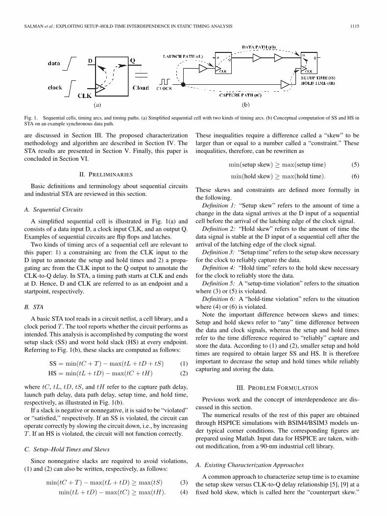
Fig. 1. Sequential cells, timing arcs, and timing paths. (a) Simplified sequential cell with two kinds of timing arcs. (b) Conceptual computation of SS and HS inSTA on an example synchronous data path.
are discussed in Section III. The proposed characterizationmethodology and algorithm are described in Section IV. TheSTA results are presented in Section V. Finally, this paper isconcluded in Section VI.
II. PRELIMINARIES
Basic definitions and terminology about sequential circuitsand industrial STA are reviewed in this section.
A. Sequential Circuits
A simplified sequential cell is illustrated in Fig. 1(a) andconsists of a data input D, a clock input CLK, and an output Q.Examples of sequential circuits are flip flops and latches.
Two kinds of timing arcs of a sequential cell are relevant tothis paper: 1) a constraining arc from the CLK input to theD input to annotate the setup and hold times and 2) a propa-gating arc from the CLK input to the Q output to annotate theCLK-to-Q delay. In STA, a timing path starts at CLK and endsat D. Hence, D and CLK are referred to as an endpoint and astartpoint, respectively.
B. STA
A basic STA tool reads in a circuit netlist, a cell library, and aclock period T . The tool reports whether the circuit performs asintended. This analysis is accomplished by computing the worstsetup slack (SS) and worst hold slack (HS) at every endpoint.Referring to Fig. 1(b), these slacks are computed as follows:
SS = min(tC + T ) − max(tL + tD + tS) (1)
HS = min(tL + tD) − max(tC + tH) (2)
where tC, tL, tD, tS, and tH refer to the capture path delay,launch path delay, data path delay, setup time, and hold time,respectively, as illustrated in Fig. 1(b).
If a slack is negative or nonnegative, it is said to be “violated”or “satisfied,” respectively. If an SS is violated, the circuit canoperate correctly by slowing the circuit down, i.e., by increasingT . If an HS is violated, the circuit will not function correctly.
C. Setup–Hold Times and Skews
Since nonnegative slacks are required to avoid violations,(1) and (2) can also be written, respectively, as follows:
min(tC + T ) − max(tL + tD) ≥ max(tS) (3)
min(tL + tD) − max(tC) ≥ max(tH). (4)
These inequalities require a difference called a “skew” to belarger than or equal to a number called a “constraint.” Theseinequalities, therefore, can be rewritten as
min(setup skew) ≥ max(setup time) (5)
min(hold skew) ≥ max(hold time). (6)
These skews and constraints are defined more formally inthe following.Definition 1: “Setup skew” refers to the amount of time a
change in the data signal arrives at the D input of a sequentialcell before the arrival of the latching edge of the clock signal.Definition 2: “Hold skew” refers to the amount of time the
data signal is stable at the D input of a sequential cell after thearrival of the latching edge of the clock signal.Definition 3: “Setup time” refers to the setup skew necessary
for the clock to reliably capture the data.Definition 4: “Hold time” refers to the hold skew necessary
for the clock to reliably store the data.Definition 5: A “setup-time violation” refers to the situation
where (3) or (5) is violated.Definition 6: A “hold-time violation” refers to the situation
where (4) or (6) is violated.Note the important difference between skews and times:
Setup and hold skews refer to “any” time difference betweenthe data and clock signals, whereas the setup and hold timesrefer to the time difference required to “reliably” capture andstore the data. According to (1) and (2), smaller setup and holdtimes are required to obtain larger SS and HS. It is thereforeimportant to decrease the setup and hold times while reliablycapturing and storing the data.
III. PROBLEM FORMULATION
Previous work and the concept of interdependence are dis-cussed in this section.
The numerical results of the rest of this paper are obtainedthrough HSPICE simulations with BSIM4/BSIM3 models un-der typical corner conditions. The corresponding figures areprepared using Matlab. Input data for HSPICE are taken, with-out modification, from a 90-nm industrial cell library.
A. Existing Characterization Approaches
A common approach to characterize setup time is to examinethe setup skew versus CLK-to-Q delay relationship [5], [9] at afixed hold skew, which is called here the “counterpart skew.”

1116 IEEE TRANSACTIONS ON COMPUTER-AIDED DESIGN OF INTEGRATED CIRCUITS AND SYSTEMS, VOL. 26, NO. 6, JUNE 2007
Fig. 2. Independent constraint characterization for sequential cells. (a) Setup skew versus CLK-to-Q delay for setup-time characterization. (b) Hold skew versusCLK-to-Q delay for hold-time characterization.
Fig. 3. Constraint characterization for sequential cells at different counterpart skews. (a) Setup skew versus CLK-to-Q delay at different hold skews. (b) Holdskew versus CLK-to-Q delay at different setup skews.
The process is similar for the hold time. These approachesare shown in Fig. 2. According to [5], three regions can bedetermined for both plots, namely: 1) “stable;” 2) “metastable;”and 3) “failure” regions. The stable region is defined as theregion in which the CLK-to-Q delay is independent of the setupor hold skew. As the skew decreases, the CLK-to-Q delay startsto rise in an exponential fashion [10]. If the skew is excessivelysmall, the sequential cell fails to latch the data. This regionis called the failure region. The region between the stable andfailure regions is referred to as the metastable region.
The setup and hold times cannot fall in the failure regionsince the sequential cell is unable to latch the data in that region.The setup (hold) time is usually set to the setup (hold) skew,where the stable region crosses over into the metastable re-gion. There are different approaches to identify this “crossoverpoint,” as listed in [5]. In some approaches, the crossoverpoint is the time where a certain amount of degradation in theCLK-to-Q delay occurs. For example, 10% degradation isassumed in this paper. In some other approaches, the crossover
point is the time where the sum of the setup skew and CLK-to-Qdelay is minimized.
B. Interdependence Between Setup and Hold Times
The setup and hold times are not independent [7], but ratherthese constraints are a function of the counterpart skews (holdskew for the setup time and setup skew for the hold time).These dependences are shown in Fig. 3. Note that the setuptime decreases as the hold skew increases and that the holdtime decreases as the setup skew increases. Thus, the smallestsetup and hold times occur when the counterpart skews arethe largest.
Existing characterization approaches typically ignore theinterdependence of the setup and hold times. This strategy leadsto two main issues.
Issue 1: Ignoring the interdependence of the setup and holdtimes results in either overoptimism or pessimism, dependingon the assumption on the counterpart skew. If the counterpart
SALMAN et al.: EXPLOITING SETUP–HOLD-TIME INTERDEPENDENCE IN STATIC TIMING ANALYSIS 1117
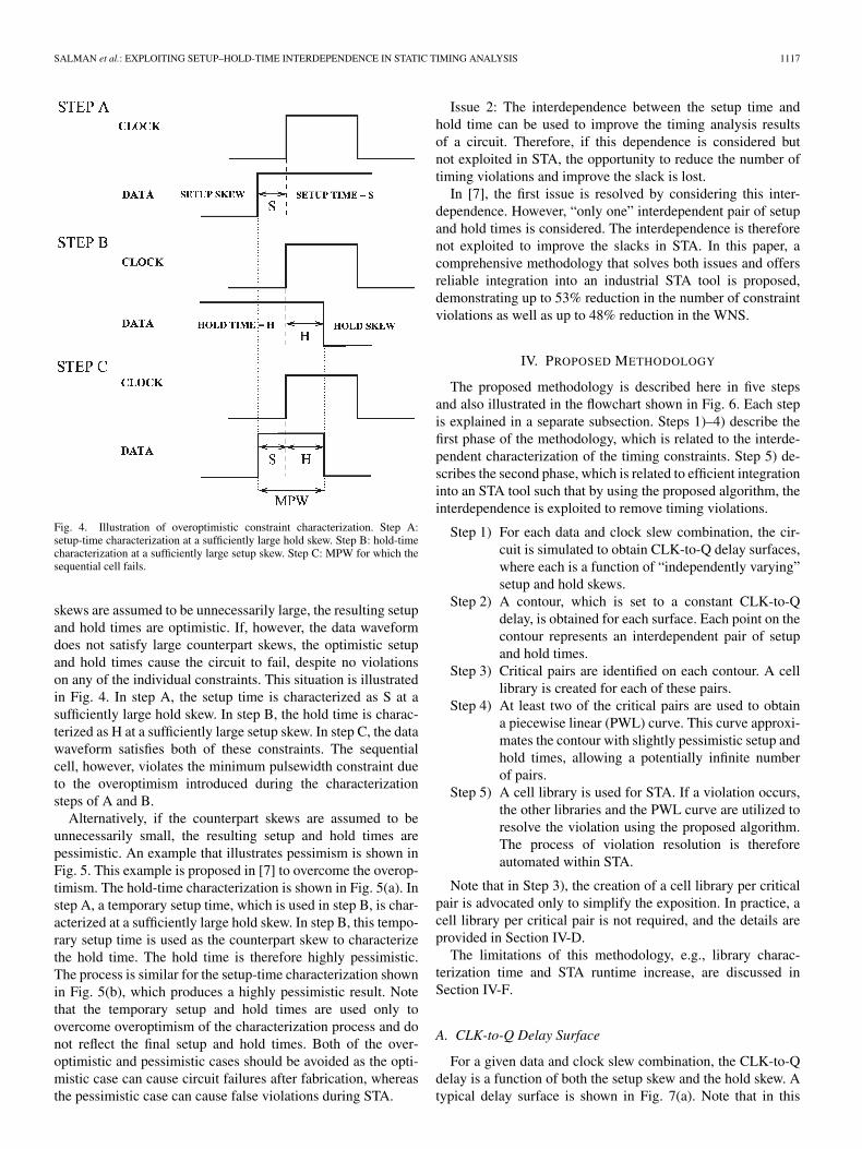
Fig. 4. Illustration of overoptimistic constraint characterization. Step A:setup-time characterization at a sufficiently large hold skew. Step B: hold-timecharacterization at a sufficiently large setup skew. Step C: MPW for which thesequential cell fails.
skews are assumed to be unnecessarily large, the resulting setupand hold times are optimistic. If, however, the data waveformdoes not satisfy large counterpart skews, the optimistic setupand hold times cause the circuit to fail, despite no violationson any of the individual constraints. This situation is illustratedin Fig. 4. In step A, the setup time is characterized as S at asufficiently large hold skew. In step B, the hold time is charac-terized as H at a sufficiently large setup skew. In step C, the datawaveform satisfies both of these constraints. The sequentialcell, however, violates the minimum pulsewidth constraint dueto the overoptimism introduced during the characterizationsteps of A and B.
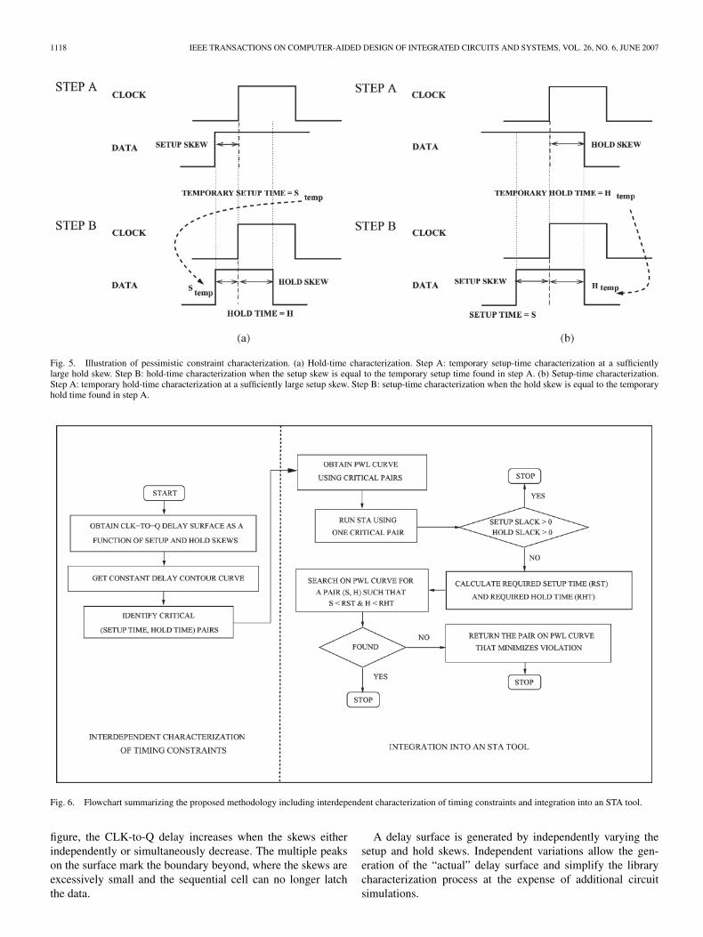
Alternatively, if the counterpart skews are assumed to beunnecessarily small, the resulting setup and hold times arepessimistic. An example that illustrates pessimism is shown inFig. 5. This example is proposed in [7] to overcome the overop-timism. The hold-time characterization is shown in Fig. 5(a). Instep A, a temporary setup time, which is used in step B, is char-acterized at a sufficiently large hold skew. In step B, this tempo-rary setup time is used as the counterpart skew to characterizethe hold time. The hold time is therefore highly pessimistic.The process is similar for the setup-time characterization shownin Fig. 5(b), which produces a highly pessimistic result. Notethat the temporary setup and hold times are used only toovercome overoptimism of the characterization process and donot reflect the final setup and hold times. Both of the over-optimistic and pessimistic cases should be avoided as the opti-mistic case can cause circuit failures after fabrication, whereasthe pessimistic case can cause false violations during STA.
Issue 2: The interdependence between the setup time andhold time can be used to improve the timing analysis resultsof a circuit. Therefore, if this dependence is considered butnot exploited in STA, the opportunity to reduce the number oftiming violations and improve the slack is lost.
In [7], the first issue is resolved by considering this inter-dependence. However, “only one” interdependent pair of setupand hold times is considered. The interdependence is thereforenot exploited to improve the slacks in STA. In this paper, acomprehensive methodology that solves both issues and offersreliable integration into an industrial STA tool is proposed,demonstrating up to 53% reduction in the number of constraintviolations as well as up to 48% reduction in the WNS.
IV. PROPOSED METHODOLOGY
The proposed methodology is described here in five stepsand also illustrated in the flowchart shown in Fig. 6. Each stepis explained in a separate subsection. Steps 1)–4) describe thefirst phase of the methodology, which is related to the interde-pendent characterization of the timing constraints. Step 5) de-scribes the second phase, which is related to efficient integrationinto an STA tool such that by using the proposed algorithm, theinterdependence is exploited to remove timing violations.
Step 1) For each data and clock slew combination, the cir-cuit is simulated to obtain CLK-to-Q delay surfaces,where each is a function of “independently varying”setup and hold skews.
Step 2) A contour, which is set to a constant CLK-to-Qdelay, is obtained for each surface. Each point on thecontour represents an interdependent pair of setupand hold times.
Step 3) Critical pairs are identified on each contour. A celllibrary is created for each of these pairs.
Step 4) At least two of the critical pairs are used to obtaina piecewise linear (PWL) curve. This curve approxi-mates the contour with slightly pessimistic setup andhold times, allowing a potentially infinite numberof pairs.
Step 5) A cell library is used for STA. If a violation occurs,the other libraries and the PWL curve are utilized toresolve the violation using the proposed algorithm.The process of violation resolution is thereforeautomated within STA.
Note that in Step 3), the creation of a cell library per criticalpair is advocated only to simplify the exposition. In practice, acell library per critical pair is not required, and the details areprovided in Section IV-D.
The limitations of this methodology, e.g., library charac-terization time and STA runtime increase, are discussed inSection IV-F.
A. CLK-to-Q Delay Surface
For a given data and clock slew combination, the CLK-to-Qdelay is a function of both the setup skew and the hold skew. Atypical delay surface is shown in Fig. 7(a). Note that in this
1118 IEEE TRANSACTIONS ON COMPUTER-AIDED DESIGN OF INTEGRATED CIRCUITS AND SYSTEMS, VOL. 26, NO. 6, JUNE 2007
Fig. 5. Illustration of pessimistic constraint characterization. (a) Hold-time characterization. Step A: temporary setup-time characterization at a sufficientlylarge hold skew. Step B: hold-time characterization when the setup skew is equal to the temporary setup time found in step A. (b) Setup-time characterization.Step A: temporary hold-time characterization at a sufficiently large setup skew. Step B: setup-time characterization when the hold skew is equal to the temporaryhold time found in step A.
Fig. 6. Flowchart summarizing the proposed methodology including interdependent characterization of timing constraints and integration into an STA tool.
figure, the CLK-to-Q delay increases when the skews eitherindependently or simultaneously decrease. The multiple peakson the surface mark the boundary beyond, where the skews areexcessively small and the sequential cell can no longer latchthe data.
A delay surface is generated by independently varying thesetup and hold skews. Independent variations allow the gen-eration of the “actual” delay surface and simplify the librarycharacterization process at the expense of additional circuitsimulations.

SALMAN et al.: EXPLOITING SETUP–HOLD-TIME INTERDEPENDENCE IN STATIC TIMING ANALYSIS 1119
Fig. 7. Interdependent constraint characterization of a sequential cell. (a) CLK-to-Q delay surface as a function of independently varying setup skew and holdskew. (b) Contour at a 10%-degraded CLK-to-Q delay. The contour includes the critical pairs as well as a PWL approximation. Regions 1 and 2 are the pessimisticand optimistic regions, respectively.
Every point on the CLK-to-Q delay surface corresponds toa skew pair, which is denoted as (setup skew, hold skew).If a particular pair on this surface is identified as the final(setup time, hold time) pair, issue 1 in Section III-B is resolvedbecause the setup and hold times at this point are nowinterdependent.
Different approaches exist to select a final pair on the surface,depending on the definition of the crossover point [7]. Irrespec-tive of the approach used, it is highly likely that there will bemultiple final pairs that satisfy this definition.
B. Constant Delay Contour
The definition of a common crossover point is a specific percent degradation in the CLK-to-Q delay. Once the CLK-to-Qdelay surface in three dimensions is obtained, all of the finalpairs can be extracted from the constant delay contour as a percent of the crossover point.
The contour obtained at a 10%-degraded CLK-to-Q delayis depicted in Fig. 7(b). Each (setup time, hold time) pair onthis contour is interdependent and valid. Furthermore, any pairin region 1 is also valid with additional pessimism, whereasany pair in region 2 is invalid, as the pairs in this region areoptimistic.
Two important conclusions can be drawn from this contour.1) Rather than individual and independent setup and hold
times, there are multiple and interdependent (setup time,hold time) pairs. Any pair can be chosen depending onthe potential to remove timing violations.
2) As indicated in Fig. 7(b), the setup and hold times areinversely proportional, which can also be verified byleast square regression analysis. Hence, a small setuptime can be obtained at the expense of a large hold time(or vice versa).
C. Critical Pairs on Contour
The following pairs on the contour are defined as criticalpairs because these pairs are appropriate candidates to includein a cell library. For each pair X , the notation X = (s, h),where s[X] = s and h[X] = h, is used.Definition 7: P is defined as the set of all (s, h) pairs on the
contour, where s is the setup time and h is the hold time.Definition 8: S and H are defined as the set of all setup
times s and hold times h on the contour, respectively.Definition 9: The “minimum setup pair (MSP)” is defined as
the pair (s, h) in P such that s is minimum in S. More formally,
MSP = (s, h) ∈ P such that s = min∀s∈S
(s). (7)
Definition 10: The “minimum hold pair (MHP)” is definedas the pair (s, h) in P such that h is minimum in H . Moreformally,
MHP = (s, h) ∈ P such that h = min∀h∈H
(h). (8)
The setup (hold) time of MHP (MSP) can be impracticallylarge to minimize the corresponding hold (setup) time. If aslightly larger but bounded increase (controlled by a param-eter ε) in hold (setup) time is allowed, the setup (hold) timeof MHP (MSP) can be reduced to an acceptable level. Thisreduction is achieved by the effective hold (setup) pair.Definition 11: The “effective setup pair (ESP)” is formally
defined as
ESP = (s, h) ∈ P such that s = s[MSP] + εs ∗ |s[MSP]| (9)
where εs is a user-controlled nonnegative parameter.

1120 IEEE TRANSACTIONS ON COMPUTER-AIDED DESIGN OF INTEGRATED CIRCUITS AND SYSTEMS, VOL. 26, NO. 6, JUNE 2007
Fig. 8. Relationship between the constraints and the minimum pulsewidth. (a) Setup time versus minimum pulsewidth. (b) Hold time versus minimum pulsewidth.
Definition 12: The “effective hold pair (EHP)” is formallydefined as
EHP=(s, h) ∈ P such that h=h[MHP]+ εh∗ |h[MHP]| (10)
where εh is a user-controlled nonnegative parameter.Definition 13: The “minimum setup–hold pair (MSHP)” is
defined as the pair (s, h) in P such that the summation of s andh is the minimum. More formally,
MSHP = (s, h)∈P such that s + h = min
∑∀(s,h)∈P
(s + h)
.
(11)
Note that MSHP corresponds to the minimum data pulsewidth(MPW) possible that can be captured and stored by the sequen-tial cell.
The distinction between the minimum and effective pairscan be illustrated by evaluating the minimum pulsewidth ofthe data signal. The minimum pulsewidth of the data signal isdetermined by summing the setup and hold times.
The variation of the minimum pulsewidth with respect to thesetup and hold times is shown in Fig. 8. If the minimum con-straints are used, rather than effective constraints, the minimumpulsewidth increases significantly. Note that at zero εs and εh,the effective constraints are equal to the minimum constraints.
D. PWL Approximation of Contour
In order to fully exploit this interdependence, the STA toolshould use at least two (setup time, hold time) pairs on thecontour. Since library characterization is expensive in timeand memory, it may be impractical to generate more than twoor three pairs. These pairs may, however, be insufficient toremove all violations. An improvement is to generate criticalpairs and connect these critical pairs using a PWL curve toapproximate the contour. For example, an approximation withtwo line segments, i.e., linear, can be obtained by connectingESP and EHP, and an approximation with three line segmentscan be obtained by connecting ESP, MSHP, and EHP.
To avoid optimism in the PWL approximation, the contourshould be convex with respect to the PWL approximation,i.e., as illustrated in Fig. 7(b), the line segments of the PWLapproximation of the contour should remain in region 1.
The linear representation of the contour at three differentdata and clock slew pairs is shown in Fig. 9. The slews arecomputed with respect to 10% and 90% thresholds of the signalvoltages. Each linear curve is obtained using ESP and EHP onthe contour when εs = 0 and εh = 0.2. Note that the numberof critical pairs used in the PWL curve represents a tradeoffbetween accuracy and complexity.
To represent critical pairs in cell libraries for sequentialcells, the following is proposed. Current cell libraries generallycontain two lookup tables for setup time and two tables forhold time (one table is defined for the rising edge data signal,and the other table is defined for the falling-edge data signal).Therefore, if two critical pairs are used, there are two possibleoptions depending on the flexibility of the library format. If aslight modification is allowed on the library format, the pro-posed methodology does not require more tables: The existingtables for setup and hold times should be modified to containinterdependent (setup time, hold time) pairs instead of inde-pendent setup time and hold times. The library, therefore, stillcontains four tables, all of which consist of (setup time, holdtime) pairs. If the current library format cannot be modified,the proposed methodology requires four additional tables: twotables for setup time and two tables for hold time to sufficientlyrepresent (setup time, hold time) pairs. For both options, eachtable should be identified with the corresponding critical pairname. Note that if more than two critical pairs are used, thecorresponding modifications can be reasoned similarly.
E. Integration of Interdependent Characterization Into STA
The FIND-BEST-PAIR algorithm shown in Fig. 10 is pro-posed to exploit the interdependence of the setup and hold timesin STA.1) FIND-BEST-PAIR Algorithm: FIND-BEST-PAIR reads
in the PWL representation P of the contour as an input. This

SALMAN et al.: EXPLOITING SETUP–HOLD-TIME INTERDEPENDENCE IN STATIC TIMING ANALYSIS 1121
Fig. 9. Linear representations using two pairs, ESP and EHP, where εs = 0 and εh = 0.2. (a) At different data slews. (b) At different clock slews.
Fig. 10. FIND-BEST-PAIR algorithm to determine the (setup time, hold time)pair that removes the violation using the pairs P on the PWL approximationof the contour curve. This algorithm is run only for sequential cells withviolations.
representation is obtained using critical (setup time, hold time)pairs, as described in Section IV-D. The critical pairs are sortedin descending order of setup times such that two successivepairs imply a line segment. The PWL representation P there-fore contains a set of connected line segments.
At line 1 of FIND-BEST-PAIR, the (setup time, hold time)pair with the largest setup time is selected from the input.Note that this pair can be any of the critical pairs on P , butit is suggested here to use EHP, as hold times are typicallymore critical. The SS and HS are determined as described inSection II-B. Both slacks are checked for violations. If bothare nonnegative, the algorithm terminates, returning the pair asthe “best” pair. If one or both of the slacks are negative, theseslacks are used to compute the “required setup time (RST)” and“required hold time (RHT)” to remove the violations. The loopat line 8 determines if such a pair actually exists in P . This lineenables the tool to dynamically switch between interdependent(setup time, hold time) pairs to determine the best pair. If a pairthat can remove the violations is found, that pair is returnedas the best pair at line 12. If no such pair exists, the RST and
RHT are returned at line 13 with a warning that no solution ispossible. Note that the RST and RHT can be used to search fora pair that minimizes the violations.
The loop at line 8 iterates over each pair (si, hi) in P (exceptthe first pair since the first pair has already been checked beforethe loop) in order to determine if the line segment from (si, hi)to (si−1, hi−1) contains any pairs that can resolve both setup-and hold-time violations. The condition at line 9 determinesif si is smaller than or equal to the RST. If this conditionis satisfied, line 10 computes hold time h such that the pair(RST, h) is on the line segment from (si−1, hi−1) to (si, hi).The computation of hold time h is achieved using the equationof the line segment. If the condition at line 11 is also satisfied,the pair (RST, h) can resolve both violations. The algorithm ter-minates, returning this pair as the best pair at line 12. If line 12is not reached during the iterations of the loop at line 8, thealgorithm terminates with no solution, which is indicated bythe returned value at line 13.2) Examples: The behavior of the algorithm is illustrated for
two different cases in Fig. 11. The situation for which FIND-BEST-PAIR determines a solution and removes the violations isillustrated in Fig. 11(a). The situation for which FIND-BEST-PAIR fails to determine a solution is illustrated in Fig. 11(b).For both figures, the original contour curve is represented bythe function h(s), which is the hold time as a function of thesetup time. Note that for simplicity, only two pairs are used inboth cases for the PWL approximation. Therefore, only one linesegment, which is defined by the pairs (s0, h0) and (s1, h1),exists, as shown in Fig. 11.
The shaded regions in Fig. 11 represent all of the pairs whosesetup time is smaller than or equal to the RST and whose holdtime is smaller than or equal to the RHT. The pairs that are at theintersection of the shaded region and the PWL approximationcan therefore resolve both violations. For Fig. 11(a), FIND-BEST-PAIR exits at line 12, returning pair B since pair B isat the intersection. For Fig. 11(b), FIND-BEST-PAIR exits atline 13, returning pair D because the PWL approximation does

1122 IEEE TRANSACTIONS ON COMPUTER-AIDED DESIGN OF INTEGRATED CIRCUITS AND SYSTEMS, VOL. 26, NO. 6, JUNE 2007
Fig. 11. Illustration of the cases for which FIND-BEST-PAIR (a) determines a solution and (b) cannot determine a solution. The actual contour curve isrepresented as h(s), which is the hold time as a function of the setup time (RST, required setup time; RHT, required hold time). For (a), the algorithm returnspoint B as the best pair; the bold region of the PWL curve represents all of the pairs that can be returned. For (b), the algorithm returns point D because the PWLcurve does not intersect with the shaded region, indicating that a solution is not possible.
Fig. 12. Constant delay contour curve illustrating the characterization pointsof the three prototype libraries.
not intersect with the shaded region. In this case, therefore, nopair that can remove the setup- and hold-time violations exists.
Pairs A and C, which are shown in Fig. 11(a) and (b),respectively, illustrate the tradeoff between accuracy and com-plexity in terms of the number of pairs included in the PWLapproximation. Pair A is on the actual contour in Fig. 11(a)and produces a larger HS value. Pair A, however, cannot bereturned because it is not included in the PWL approximation.Similarly, for Fig. 11(b), pair C is also on the actual contourand can remove both violations since it is inside the shadedregion. Pair C, however, cannot be returned because it is notincluded in the PWL approximation. A tradeoff therefore existsbetween accuracy and complexity in terms of the number ofpairs included in the PWL approximation.
As shown in Fig. 11(a), FIND-BEST-PAIR returns the pairthat minimizes the hold time. However, any pair that is at theintersection of the PWL curve and the shaded region [shownas the darker portion in Fig. 11(a)] can be returned. Note thatadapting the algorithm to return any other valid pair is possible.3) Complexity Analysis: In order to evaluate the time com-
plexity of FIND-BEST-PAIR, the total number of sequentialcells in the circuit is assumed to be N , which is a small fractionof the total number of cells in the circuit. FIND-BEST-PAIRexecutes for each sequential cell that violates a setup- or hold-time constraint. In the worst case, all of the N sequential cellshave a timing violation. FIND-BEST-PAIR, therefore, executesN times in the worst case. For each execution, the algorithmrequires time that is proportional to the number of pairs ininput P because the loop at line 8 iterates P times and each iter-ation takes constant time. The time complexity of FIND-BEST-PAIR is therefore O(|P |), and the complexity of resolvingN violations using this algorithm is O(N |P |). In practice, P isexpected to be two or three pairs. FIND-BEST-PAIR thereforeexecutes in constant time, and the N iterations of FIND-BEST-PAIR execute in O(N) time. This time complexity is optimalsince an optimal algorithm for violation resolution should exe-cute in constant time per violation.
F. Limitations
The primary limitations of the proposed methodology aretwofold: 1) The constraint characterization time increases forsequential cells. 2) The STA runtime increases if there is atiming violation. The first limitation is due to the generationof the delay surfaces, and the second limitation is due to the useof multiple constraints during STA.
The second limitation is not significant as the STA runtimeincreases only if there is a timing violation after analyzing thefirst (setup time, hold time) pair. Furthermore, if there is a viola-tion, any other resolution method will also increase the overall

SALMAN et al.: EXPLOITING SETUP–HOLD-TIME INTERDEPENDENCE IN STATIC TIMING ANALYSIS 1123
TABLE IABSOLUTE (ABS) AND RELATIVE (REL) IMPROVEMENTS OF TWO CIRCUITS WITH RESPECT TO LIBRARY 3. WNS IS THE WORST
NEGATIVE SLACK, ∆WNS IS THE INCREASE IN WNS, AND ∆N IS THE DECREASE IN THE NUMBER OF VIOLATIONS
Fig. 13. Slack histograms for circuit A. (a) SS histograms of library 3 and library 1. (b) HS histograms of library 3 and library 2.
time. Since the current resolution methods are not automated,as proposed in this paper, the time for violation resolutionmay actually decrease with the proposed methodology. Notethat the second limitation can be mitigated by using linearapproximation.
In order to quantify the first limitation, assume that Ns andNh denote the number of setup skews and hold skews to sweepover for characterization. For the overoptimistic characteriza-tion approach illustrated in Fig. 4, the total number of simula-tions to characterize both setup and hold times is equal to Ns +Nh. For the pessimistic characterization approach illustrated inFig. 5, the total number of simulations doubles to 2(Ns + Nh)due to the additional steps. For the proposed characterizationapproach, the total number of simulations increases to NsNh inthe worst case to generate the entire CLK-to-Q delay surface,as illustrated in Fig. 7(a).
To reduce the number of simulations for the proposed ap-proach, a simple heuristic is used to reduce the number of skewsto be swept by eliminating those skew pairs that do not change
the delay surface. For example, the location of the critical pairson the contour shown in Fig. 7(b) indicate that it is not neces-sary to sweep the skew pairs falling in region 1.
V. STA RESULTS
A 90-nm library is used as a template to generate three newcell libraries: library 1, library 2, and library 3. As discussedin Section IV and IV-D, separate libraries are generated tosimplify the evaluation of the methodology with an industrialSTA environment. The sequential cells of each library arecharacterized using HSPICE with BSIM4/BSIM3 models undertypical corner conditions.
The library characterization points for these three librariesare illustrated on a contour at 10%-degraded CLK-to-Q delayin Fig. 12. Both libraries 1 and 2 are on the contour: Library 1is at ESP, and library 2 is at EHP. Library 3 is not on thecontour; this last library uses setup times from EHP and holdtimes from ESP and, as such, is an example of independent and

1124 IEEE TRANSACTIONS ON COMPUTER-AIDED DESIGN OF INTEGRATED CIRCUITS AND SYSTEMS, VOL. 26, NO. 6, JUNE 2007
Fig. 14. Slack histograms for circuit B. (a) SS histograms of library 3 and library 1. (b) HS histograms of library 3 and library 2.
pessimistic characterization. The optimistic point that resultsfrom using relatively large counterpart skews is also shown inthe figure. Note that the contour shown in Fig. 12 representsa single data-and-clock-slew combination of 25 ps each. ForSTA results, the same contour is obtained for each data-and-clock-slew combination that exists in the cell library. Differentgains are obtained by using library 1 or library 2 over library 3,depending on these slew combinations.
An industrial sign-off STA tool, PrimeTime, is used to eval-uate each prototype library on two industrial circuits: circuit Aand circuit B. Both circuits are networking cores with nearly20 000 cells. The clock frequencies of circuit A and circuit Bare set to 666 and 400 MHz, respectively.
From STA, the smallest negative slack value, which is re-ferred to as the WNS, and the number of violations are obtainedfor each of the endpoints. The STA results are listed in Table I.Each row corresponds to one simulation with one circuit andone library.
The WNS and the number of violations from library 3 aretaken as a baseline, and the absolute and relative improvementsare computed in the WNS and the number of violations with re-spect to library 3. Improvements in the WNS and the number ofviolations correspond to an increase in the WNS and a decreasein the number of violations, respectively. Note that library 1illustrates improvements in the setup time without affecting thehold time and that library 2 illustrates improvements in the holdtime without affecting the setup time. This result is becauselibrary 1 is characterized at ESP and library 2 is characterizedat EHP, as shown in Fig. 12.
As listed in Table I, the improvement in the setup WNS is369 ps (or 48.2%). This improvement corresponds to nearly
15% of the clock period. The improvement in the hold WNSis 181 ps (or 37.1%). In terms of the number of violations,the improvement in the setup case is 53.3%, and that in thehold case is 9.9%. Note that for hold-time improvements, thecase represented by the last row, where only hold-time violationis removed, is ignored. The improvement in the setup WNSprovides 14% and 15% increase in performance for circuits Aand B, respectively. Furthermore, the improvement in the holdWNS reduces the required circuit modifications to remove thehold-time violations.
These improvements can also be illustrated by means of slackhistograms over all the endpoints rather than a single numbersuch as WNS. The histograms for the two circuits are shownin Figs. 13 and 14. For both histograms, there is a shift towardthe positive side, indicating improvements in “almost all” of theslack values. The baseline is the slacks from library 3.
VI. CONCLUSION
A two-phase methodology is presented to exploit setup–hold-time interdependence in STA. The issues related with inde-pendent characterization, i.e., overoptimism and pessimism,are discussed and illustrated. Interdependent constraint char-acterization to remove these problems is proposed in the firstphase of the methodology. In the second phase, an efficientalgorithm is presented to integrate this interdependence intoan STA tool such that multiple constraint pairs are exploitedto reduce timing violations. The proposed algorithm automatesthe violation resolution process with linear-time complexity.The methodology is validated using industrial circuits andan industrial sign-off STA tool. The results show up to 53%

SALMAN et al.: EXPLOITING SETUP–HOLD-TIME INTERDEPENDENCE IN STATIC TIMING ANALYSIS 1125
reduction in the number of constraint violations as well as up to48% reduction in the WNS, corresponding to a 15% decreasein the clock period.
REFERENCES
[1] W. Roethig, “Library characterization and modeling for 130 nm and90 nm SOC design,” in Proc. IEEE Int. SOC Conf., Sep. 2003,pp. 383–386.
[2] D. Patel, “CHARMS: Characterization and modeling system for accuratedelay prediction of ASIC designs,” in Proc. IEEE Custom Integr. CircuitsConf., May 1990, pp. 9.5.1–9.5.6.
[3] R. W. Phelps, “Advanced library characterization for high-performanceASIC,” in Proc. IEEE Int. ASIC Conf., Sep. 1991, pp. 15-3.1–15-3.4.
[4] M. A. Cirit, “Characterizing a VLSI standard cell library,” in Proc. IEEECustom Integr. Circuits Conf., May 1991, pp. 25-7.1–25-7.4.
[5] V. Stojanovic and V. G. Oklobdzija, “Comparative analysis of master-slave latches and flip-flops for high-performance and low-power systems,”IEEE J. Solid-State Circuits, vol. 34, no. 4, pp. 536–548, Apr. 1999.
[6] A. M. Jain and D. Blaauw, “Modeling flip flop delay dependencies intiming analysis,” presented at the ACM/IEEE Timing Issues (TAU) Work-shop, Austin, TX, Feb. 2004.
[7] G. Rao and K. Howick, “Apparatus for optimized constraint charac-terization with degraded options and associated methods,” U.S. Patent6 584 598 B2, Jun. 24, 2003.
[8] E. K. Howick, “Conquering the high-frequency domain with predictablesequential models,” in Proc. Electr. and Phys. Des. Conf., Jan. 2002,CD-ROM.
[9] N. Weste and D. Harris, CMOS VLSI Design. Reading, MA: Addison-Wesley, 2004.
[10] M. Shoji, Theory of CMOS Digital Circuits and Circuit Failures.Princeton, NJ: Princeton Univ. Press, 1992.
Emre Salman (S’02) received the B.S. degree in mi-croelectronics engineering from Sabanci University,Istanbul, Turkey, in 2004, and the M.S. degree inelectrical and computer engineering from the Uni-versity of Rochester, Rochester, NY, in 2006. He iscurrently working toward the Ph.D. degree at theUniversity of Rochester.
In 2005, he interned at Synopsys Inc., MountainView, CA, where he worked on pessimism reductionin static timing analysis and cell library characteriza-tion. In 2006, he was an Intern with Freescale Semi-
conductor Inc., Tempe, AZ, where he developed methodologies for the analysisand reduction of substrate noise coupling for large-scale mixed-signal circuits.His research interests include analysis, modeling, and design methodologiesfor high-performance digital and mixed-signal integrated circuits, focusing onsignal integrity, noise coupling, global interconnects such as power and clocknetworks, and timing analysis.
Ali Dasdan (S’93–M’00) received the Ph.D. degreein computer science from the University of Illinois,Urbana-Champaign, in 1999.
From 1997 to 1999, he was a Visiting Scholarwith the Center for Embedded Computer Systems,University of California, Irvine. From 1999 to 2003,he was a member of Technical Staff with the Ad-vanced Technology Group, Synopsys, Inc., where hecontributed to the first releases of SystemC libraryand SystemC Compiler, and to the ATG-SI test chipto study multithreshold voltage and signal integrity
effects on 0.13-µm and below process technologies. From 2003 to 2005, he wasa Technical Lead with the PrimeTime Static Timing Analysis Group, Synopsys,Inc., where he led the variation-aware/statistical PrimeTime tool (PrimeTimeVX) from its conception to its beta release. He also made key contributions tovariation-aware cell/net models and parameterized parasitics extraction. SinceJanuary 2006, he has been a Technical Lead for various projects at the SearchEngine Group, Yahoo, Inc., Santa Clara, CA.
Feroze Taraporevala (S’86–M’88) received theB.E. degree in electrical engineering from Birla In-stitute of Technology and Science, Pilani, India, in1985 and the M.S. degree in computer engineeringfrom University of Texas, Austin, in 1988.
From 1988 to 2004, he was with LSI Logic Com-pany, ViewLogic Company, and Monterey DesignSystems. Since 2004, he has been with Synopsys,Inc., Mountain View, CA. His research interests in-clude a variety of topics on CAD and VLSI.
Kayhan Küçükçakar (M’91) received the M.S. andPh.D. degrees in electrical engineering from the Uni-versity of Southern California, Los Angeles, in 1987and 1991, respectively.
He is currently the R&D Director of Synop-sys, Inc., Mountain View, CA, and is responsiblefor PrimeTime and PrimeTime VX. Before joiningPrimeTime in 1999, he was with Motorola for sixyears, managing an internal architectural synthesistool development. He is the author of 19 papers andthe holder of seven U.S. patents.
Dr. Küçükçakar has served on the technical program committees of theInternational Workshop on Timing Issues, the International Workshop onHardware/Software Co-Design, the International Symposium on System Syn-thesis, Design, Automation and Test in Europe, and the European Design andTest Conference.
Eby G. Friedman (S’78–M’79–SM’90–F’00) re-ceived the B.S. degree from Lafayette College,Easton, PA, in 1979 and the M.S. and Ph.D. degreesfrom the University of California, Irvine, in 1981 and1989, respectively, all in electrical engineering.
From 1979 to 1991, he was with Hughes AircraftCompany, rising to the position of Manager of theSignal Processing Design and Test Department, andwas responsible for the design and test of high-performance digital and analog ICs. Since 1991,he has been with the Department of Electrical and
Computer Engineering, University of Rochester, Rochester, NY, where he iscurrently a Distinguished Professor, the Director of the High PerformanceVLSI/IC Design and Analysis Laboratory, and the Director of the Center forElectronic Imaging Systems. He is also a Visiting Professor at the Technion-Israel Institute of Technology, Haifa, Israel. He is the author of more than 300papers and book chapters, and several patents, and the author and editor of eightbooks in the fields of high-speed and low-power CMOS design techniques,high-speed interconnect, and the theory and application of synchronous clockand power distribution networks. His current research and teaching interests in-clude high-performance synchronous digital and mixed-signal microelectronicdesign and analysis, with application to high-speed portable processors andlow-power wireless communications.
Dr. Friedman is the Regional Editor of the Journal of Circuits, Systemsand Computers, a member of the Editorial Boards of the Analog IntegratedCircuits and Signal Processing, Microelectronics Journal, the Journal of LowPower Electronics, and the Journal of VLSI Signal Processing, the Chair ofthe IEEE TRANSACTIONS ON VERY LARGE SCALE INTEGRATION (VLSI)SYSTEMS steering committee, and a member of the technical program com-mittee of a number of conferences. He was the Editor-in-Chief of the IEEETRANSACTIONS ON VERY LARGE SCALE INTEGRATION (VLSI) SYSTEMS,a member of the Editorial Board of the Proceedings of the IEEE and the IEEETRANSACTIONS ON CIRCUITS AND SYSTEMS II—ANALOG AND DIGITAL
SIGNAL PROCESSING, a member of the Circuits and Systems Society Board ofGovernors, and the Program and Technical Chair of several IEEE conferences.He is a recipient of the University of Rochester Graduate Teaching Awardand the College of Engineering Teaching Excellence Award. He is a SeniorFulbright Fellow.