external interface specification using ipmi - intel® … · external interface specification using...
TRANSCRIPT

Document Number: 322999-001
Intel® Intelligent Power Node Manager 1.5External Interface Specification Using IPMI
December 2009

2 Intel® Intelligent Power Node Manager 1.5 External Interface Specification Using IPMI
Legal Lines and DisclaimersINFORMATION IN THIS DOCUMENT IS PROVIDED IN CONNECTION WITH INTEL® PRODUCTS. NO LICENSE, EXPRESS OR IMPLIED, BY ESTOPPEL OR OTHERWISE, TO ANY INTELLECTUAL PROPERTY RIGHTS IS GRANTED BY THIS DOCUMENT. EXCEPT AS PROVIDED IN INTEL'S TERMS AND CONDITIONS OF SALE FOR SUCH PRODUCTS, INTEL ASSUMES NO LIABILITY WHATSOEVER, AND INTEL DISCLAIMS ANY EXPRESS OR IMPLIED WARRANTY, RELATING TO SALE AND/OR USE OF INTEL PRODUCTS INCLUDING LIABILITY OR WARRANTIES RELATING TO FITNESS FOR A PARTICULAR PURPOSE, MERCHANTABILITY, OR INFRINGEMENT OF ANY PATENT, COPYRIGHT OR OTHER INTELLECTUAL PROPERTY RIGHT. Intel products are not intended for use in medical, life saving, life sustaining, critical control or safety systems, or in nuclear facility applications.
Intel may make changes to specifications and product descriptions at any time, without notice.
Designers must not rely on the absence or characteristics of any features or instructions marked “reserved” or “undefined.” Intel reserves these for future definition and shall have no responsibility whatsoever for conflicts or incompatibilities arising from future changes to them.
The Intel® Intelligent Power Node Manager 1.5 may contain design defects or errors known as errata which may cause the product to deviate from published specifications. Current characterized errata are available on request.
Intel software products are copyrighted by and shall remain the property of Intel Corporation. Use, duplication, or disclosure is subject to restrictions stated in Intel's Software License Agreement, or in the case of software delivered to the government, in accordance with the software license agreement as defined in FAR 52.227-7013.
Code names presented in this document are only for use by Intel to identify a product, technology, or service in development, that has not been made commercially available to the public, i.e., announced, launched or shipped. It is not a "commercial" name for products or services and is not intended to function as a trademark.Contact your local Intel sales office or your distributor to obtain the latest specifications and before placing your product order.
I2C is a two-wire communications bus/protocol developed by Philips. SMBus is a subset of the I2C bus/protocol and was developed by Intel. Implementations of the I2C bus/protocol may require licenses from various entities, including Philips Electronics N.V. and North American Philips Corporation.
Copies of documents which have an order number and are referenced in this document, or other Intel literature may be obtained by calling 1-800-548-4725 or by visiting Intel's website at http://www.intel.com.
Intel,Intel® Intelligent Power Node Manager, Xeon and the Intel logo are trademarks of Intel Corporation in the United States and other countries.
*Other names and brands may be claimed as the property of others.
Copyright © 2009, Intel Corporation. All Rights Reserved.
Intel® Intelligent Power Node Manager 1.5 External Interface Specification Using IPMI 3
Contents
1 Introduction ..............................................................................................................71.1 Scope ................................................................................................................7
1.1.1 System States and Power Management .......................................................71.2 Reference Documents ..........................................................................................71.3 Overview ...........................................................................................................7
1.3.1 Use Cases ...............................................................................................81.3.2 Intel® Intelligent Power Node Manager Use Cases........................................91.3.3 Features ............................................................................................... 17
2 Requirements on Platform Components................................................................... 212.1 Intel® Intelligent Power Node Manager IPMI OEM Commands ................................. 222.2 IPMI Sensors .................................................................................................... 372.3 IPMI Events...................................................................................................... 372.4 Alerts .............................................................................................................. 422.5 Command Passing via BMC................................................................................. 422.6 Intel® Intelligent Power Node Manager Discovery.................................................. 442.7 Error Conditions ................................................................................................ 452.8 Management IPMI Interface................................................................................ 452.9 SEL Device Commands....................................................................................... 452.10 IPMI Device “Global” Commands ......................................................................... 462.11 Sensor Device Command.................................................................................... 482.12 IPMI OEM Device Commands .............................................................................. 492.13 External Intel® Intelligent Power Node Manager Configuration and Control Commands...
...................................................................................................................... 522.14 BMC Requirements for Intel® Intelligent Power Node Manager Discovery.................. 552.15 Local Platform Intel® Intelligent Power Node Manager Configuration and Control
Commands....................................................................................................... 562.16 Intel Management Engine Firmware Update IPMI Commands................................... 612.17 Online Update Flow............................................................................................ 652.18 IPMI Commands Supported in Recovery Mode....................................................... 662.19 IPMI Sensors Implemented by Platform Services FW .............................................. 67
2.19.1 CPU Temperature Sensors ....................................................................... 702.19.2 Memory Throttling Status Sensors ............................................................ 712.19.3 ICH9 Fan Speed Sensors ......................................................................... 712.19.4 ICH9 On-Die Temperature Sensors ........................................................... 712.19.5 Intel Management Engine Power State Sensor............................................ 722.19.6 Dynamic Power Intel® Intelligent Power Node Manager Event Sensor ........... 722.19.7 Dynamic Power Intel® Intelligent Power Node Manager Health Sensor .......... 722.19.8 Dynamic Power Intel® Intelligent Power Node Manager Operational Capabilities
sensor .................................................................................................. 722.19.9 Server Platform Services Firmware Health Sensor....................................... 722.19.10IPMI Platform Event Messages Generated by Platform Services FW ............... 732.19.11Generic Event/ Reading Type Codes.......................................................... 742.19.12Event Messages Definition ....................................................................... 75
2.20 Event Generation Control ................................................................................... 782.20.1 Server Platform Services Debug Event ...................................................... 792.20.2 Debug SEL Entry Definition (External) ....................................................... 792.20.3 Debug SEL Entry Definition (Internal) ....................................................... 80
2.21 Completion Codes ............................................................................................. 81
3 BMC IPMI Interface ................................................................................................. 833.1 IPMI Device “Global” Commands ......................................................................... 833.2 Sensor Device Commands .................................................................................. 83
4 Intel® Intelligent Power Node Manager 1.5 External Interface Specification Using IPMI
3.3 Alert Immediate Commands................................................................................843.4 OEM Commands Implemented by BMC .................................................................84
3.4.1 Power Consumption Readings...................................................................843.4.2 Inlet Air Temperature Readings ................................................................853.4.3 ICC_TDC Reading from PECI ....................................................................863.4.4 OEM ME Power State Change....................................................................863.4.5 OEM Command Definition ........................................................................873.4.6 Summary of Options ...............................................................................883.4.7 IPMI Command Bridging ..........................................................................883.4.8 IPMB Reset Scenarios..............................................................................88
Figures2-1 Example IPMI Command Bridging from LAN ..........................................................432-2 Intel® ME Online Update Flow.............................................................................662-3 Temperature Sensor Data Format ........................................................................712-4 16-Bit PECI Reading to 8-Bit Mapping...................................................................71
Tables1-1 Terminology....................................................................................................... 71-2 Intel® Intelligent Power Node Manager 1.5 Usage Models and Use Cases ................... 81-3 Policy Management Feature.................................................................................171-4 Monitoring and Querying Feature .........................................................................171-5 Alerts and Notifications Feature ...........................................................................181-6 External Interface ..............................................................................................181-7 Supported System Architectures ..........................................................................192-1 Intel® Intelligent Power Node Manager Interfaces to Platform Components ...............212-2 Platform Ingredients for Intel® Intelligent Power Node Manager Support ..................212-3 Intel® Intelligent Power Node Manager-specific OEM commands (IPMI) ....................222-4 Intel® Intelligent Power Node Manager IPMI Sensors .............................................372-5 Intel® Intelligent Power Node Manager IPMI Events ...............................................372-6 Intel® Intelligent Power Node Manager OEM SDR – Record Body .............................442-7 SEL Device Commands .......................................................................................452-8 Intel® Intelligent Power Node Manager OEM SDR – Record Body .............................55

Intel® Intelligent Power Node Manager 1.5 External Interface Specification Using IPMI 5
Revision History
§
Revision Number Description Date
322999-001 • Initial Public release of document. December 2009

6 Intel® Intelligent Power Node Manager 1.5 External Interface Specification Using IPMI
Intel® Intelligent Power Node Manager 1.5 External Interface Specification Using IPMI 7
Introduction
1 Introduction
1.1 ScopeThis document contains the mapping of external interface specification using Intel® Intelligent Power Node Manager version 1.5 over IPMI.
1.1.1 System States and Power Management
1.2 Reference Documents
1.3 OverviewIntel® Intelligent Power Node Manager version 1.5 is a platform resident technology that enforces power and thermal policies for the platform. These policies are applied by exploiting subsystem knobs (such as processor P and T states) that can be used to
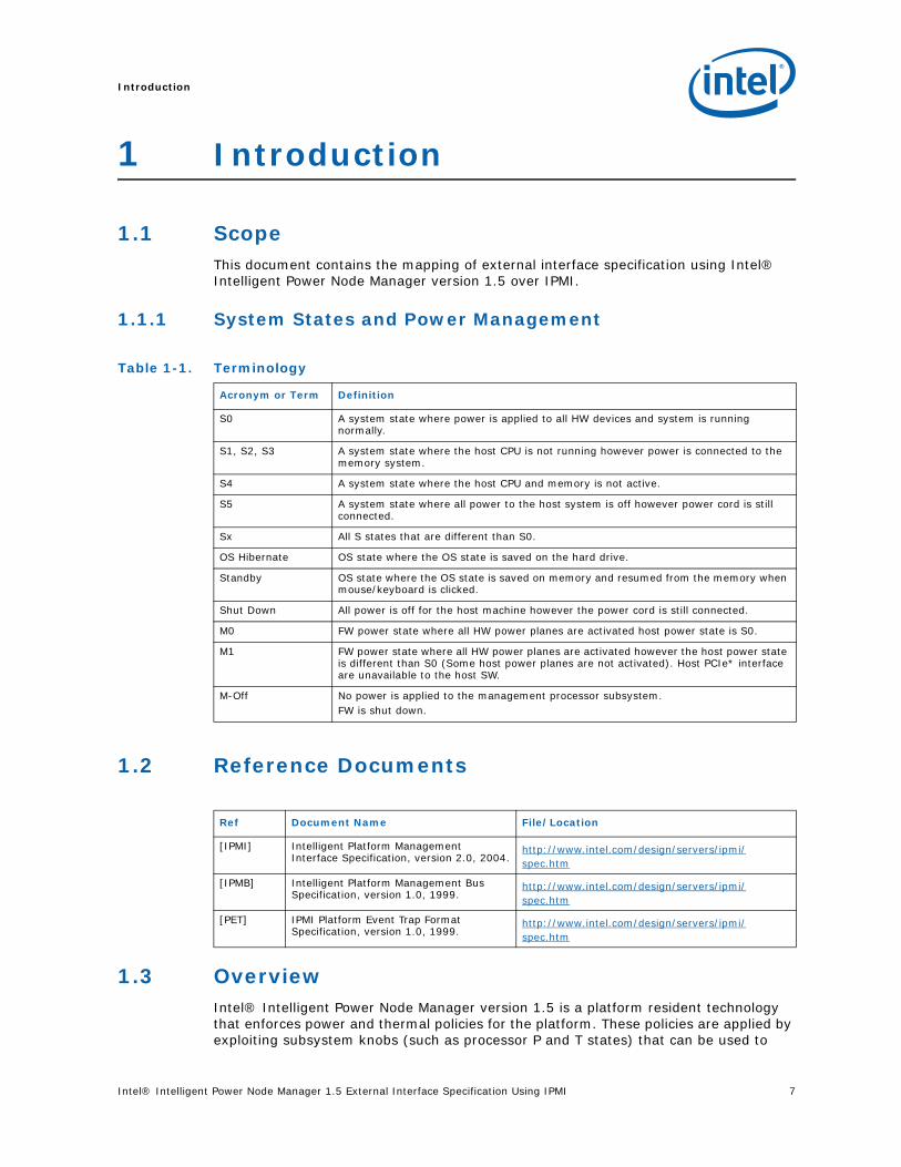
Table 1-1. Terminology
Acronym or Term Definition
S0 A system state where power is applied to all HW devices and system is running normally.
S1, S2, S3 A system state where the host CPU is not running however power is connected to the memory system.
S4 A system state where the host CPU and memory is not active.
S5 A system state where all power to the host system is off however power cord is still connected.
Sx All S states that are different than S0.
OS Hibernate OS state where the OS state is saved on the hard drive.
Standby OS state where the OS state is saved on memory and resumed from the memory when mouse/keyboard is clicked.
Shut Down All power is off for the host machine however the power cord is still connected.
M0 FW power state where all HW power planes are activated host power state is S0.
M1 FW power state where all HW power planes are activated however the host power state is different than S0 (Some host power planes are not activated). Host PCIe* interface are unavailable to the host SW.
M-Off No power is applied to the management processor subsystem. FW is shut down.
Ref Document Name File/Location
[IPMI] Intelligent Platform Management Interface Specification, version 2.0, 2004.
http://www.intel.com/design/servers/ipmi/spec.htm
[IPMB] Intelligent Platform Management Bus Specification, version 1.0, 1999.
http://www.intel.com/design/servers/ipmi/spec.htm
[PET] IPMI Platform Event Trap Format Specification, version 1.0, 1999.
http://www.intel.com/design/servers/ipmi/spec.htm

Introduction
8 Intel® Intelligent Power Node Manager 1.5 External Interface Specification Using IPMI
control power consumption. Intel® Intelligent Power Node Manager enables data center power and thermal management by exposing an external interface to management software through which platform policies can be specified. It also enables specific data center power management usage models such as power limiting.
The configuration and control commands are used by the external management software or BMC to configure and control the Intel® Intelligent Power Node Manager feature. Since Platform Services firmware does not have any external interface, external commands are first received by the BMC over LAN and then relayed to the Platform Services firmware over IPMB channel. The BMC acts as a relay and the transport conversion device for these commands. For simplicity, the commands from the management console might be encapsulated in a generic CONFIG packet format (config data length, config data blob) to the BMC so that the BMC doesn’t even have to even parse the actual configuration data.
BMC provides the access point for remote commands from external management SW and generates alerts to them. Intel® Intelligent Power Node ManagerIntel® Intelligent Power Node Manager on Intel® Manageability Engine (Intel® ME)is an IPMI satellite controller. A mechanism needs to exist to forward commands to Intel® ME and send response back to originator. Similarly events from Intel® ME have to be sent as alerts outside of BMC. It is the responsibility of BMC to implement these mechanisms for communication with Intel® Intelligent Power Node Manager.
The rest of the sections describe the details of these interfaces. The details include list of commands, sensors exposed, alerts exposed the requirement on BMC to support passing the commands and alerts to/from external SW, and about discovery of Intel® Intelligent Power Node Manager Functionality by external SW.
1.3.1 Use Cases
In this section we describe the key usage models of Intel® Intelligent Power Node Manager 1.5 (see Table 1-2 below).
To effectively manage power, we must be able to measure it and then control its usage as necessary. For this reason, Intel® Intelligent Power Node Manager is a power management technology that has two usage models: a) platform power and thermal monitoring, and b) platform power limiting.
Intel® Intelligent Power Node Manager can be used to monitor platform power and temperature over a period so that it can understand actual power usage patterns and actual thermal behavior of a server, and hence a group of servers in a data center. Once the power usage pattern is understood, appropriate power control policies can be established and specified for Intel® Intelligent Power Node Manager to enforce.
Intel® Intelligent Power Node Manager controls power by enforcing one or more policies that it has received as inputs in the form of policy directives. Intel® Intelligent Power Node Manager policy directive specifies at least the following:
Table 1-2. Intel® Intelligent Power Node Manager 1.5 Usage Models and Use Cases
Usage Model Use Cases
Power and Thermal Monitoring Platform power monitoring
Inlet temperature monitoring
Platform Power Budgeting Power limiting to optimize rack utilization
Power limiting triggered by inlet temperature threshold
Power limiting to prevent circuit breaker tripping

Intel® Intelligent Power Node Manager 1.5 External Interface Specification Using IPMI 9
Introduction
1. Power Budget: This specifies the power budget allocated to the node in watts.
2. Correction Time: This specifies the upper time limit that actual power consumption should not exceed the specified budget: this mean that spikes in actual power consumption are allowed as long as they do not exceed the correction time.
3. Policy Duration: This specifies how long the policy should be maintained. If this is not specified, Intel® Intelligent Power Node Manager assumes that the policy is in effect until it is killed or replaced by another policy.
1.3.2 Intel® Intelligent Power Node Manager Use Cases
This section describes the specific use cases for Intel® Intelligent Power Node Manager 1.5 (see Table 1-2)
1.3.2.1 Platform Power Monitoring
Mandatory/Optional: Mandatory
Description: Intel® Intelligent Power Node Manager monitors platform power consumption and hold average power over duration. It can be queried to return actual power at any given instance.
Usage: External management software periodically queries Intel® Intelligent Power Node Manager for actual wall power consumed in watts.
Actors: Management software
Preconditions: Intel® Intelligent Power Node Manager is operational and a management console is also running.
Basic Flow of Events:
1. Management software issues a query to Intel® Intelligent Power Node Manager to gather current actual platform power profile
2. Intel® Intelligent Power Node Manager gets current platform power, average power, min, max, current budget
3. Intel® Intelligent Power Node Manager returns the data in response to query
4. Management console uses the query to adjust its behavior (for example, how frequently to poll Intel® Intelligent Power Node Manager, change power directives).
Alternate Flows (event/alerts):
5. Instead of querying by polling Intel® Intelligent Power Node Manager, Management console decides to let Intel® Intelligent Power Node Manager notifies when significant thresholds are crossed.
6. Management console subscribes to one of the threshold-crossing events advertised by Intel® Intelligent Power Node Manager.
7. Intel® Intelligent Power Node Manager returns subscription Id as an indication of successful subscription.
8. Intel® Intelligent Power Node Manager sends alert notifications to subscribed management console when specified thresholds are reached.
9. Management console uses the alert notification to decide to take appropriate action (start polling more frequently, adjust power policy directives, or other action)

Introduction
10 Intel® Intelligent Power Node Manager 1.5 External Interface Specification Using IPMI
10. When management console decides that it no longer needs to be notified of the alerts, it sends an unsubscribe request to Intel® Intelligent Power Node Manager.
11. Intel® Intelligent Power Node Manager responds with a return code indicating success or failure of the request.
Exception Paths
12. None.
Post conditions: Intel® Intelligent Power Node Manageris operational and management software is also running.
1.3.2.2 Inlet Temperature Monitoring
Mandatory/Optional: Mandatory
Description: Intel® Intelligent Power Node Manager monitors server inlet temperatures periodically. If there is an alert threshold in effect, then Intel® Intelligent Power Node Manager issues an alert when the inlet (room) temperature exceeds the specified value. The threshold value can be set by policy, or it can be pre-configured to a default value such at the ASHRAE limit.
Usage: This use case allows management software (and hence IT) to monitor room ambient temperature and detect hotspots and cooling system malfunctioning. For instance, if inlet temperature does exceeds that temperature that the cooling system is supposed to deliver to the server, this could be an indication that the cooling system is not functioning correctly and an alert from Intel® Intelligent Power Node Manager allows IT to become aware of this situation and decide on an appropriate corrective action.
Actors: Management software
Preconditions: Intel® Intelligent Power Node Manager is operational and a management console is also running.
Basic Flow of Events:
1. Management software monitors Intel® Intelligent Power Node Manager for alerts to gather information about platform inlet thermal state so that it can determine thermal condition of room.
— Intel® Intelligent Power Node Manager reads inlet temperature.
2. Intel® Intelligent Power Node Manager returns an alert and temperature values when the inlet sensor exceeds a user-settable limit or the ASHRAE limit
Alternate Flows (event/alerts):
Exception Paths
None.
Post conditions: Intel® Intelligent Power Node Manager is operational and a management software is also running.
1.3.2.3 Platform Power Limiting (Abstract)
Description: This use case is the platform power control capability provided by Intel® Intelligent Power Node Manager 1.5.

Intel® Intelligent Power Node Manager 1.5 External Interface Specification Using IPMI 11
Introduction
The expected usage of this capability is to allow external management software to address key IT issues by setting a power budget for each server. For example, if there is a physical limit on the power available in a room, then IT can decide to allocate power to different servers based on their usage – servers running critical systems can be allowed more power than servers that are running less critical workload.
Specifically, power limits can be set to address the following data center scenarios:
1. Power limiting to increase rack population (see below)
2. Power limiting triggered to maintain inlet temperature threshold (see below)
3. Power limiting to prevent circuit breaker tripping (see below)
4. Power limiting on OS failure (see below)
5. Power limiting at boot time (see below)
Although these scenarios are variations of the power limiting use case described in this section, there are key differences that influence how they are implemented; for this reason, each of them have been described as separate use cases below.
Intel® Intelligent Power Node Manager maintains platform power budget that has been specified as a policy directive input. Intel® Intelligent Power Node Manager enforces the power limit by ensuring that the limit is not exceeded beyond the grace period at any time during the duration for which the policy is in effect.
In maintaining the power cap, the optimal implementation of this policy will achieve the best performance at any given power level. This means that Intel® Intelligent Power Node Manager should be intelligent in its power capping method and mechanisms.
Usage:
External management software has made the decision to set a power cap for a node. This power budget is specified to Intel® Intelligent Power Node Manager as a policy directive input. Intel® Intelligent Power Node Manager then maintains the budget by enforcing the specified policy.
If Intel® Intelligent Power Node Manager is unable to maintain the budget by reducing the power consumption of the platform, it will notify the external management software with an alert. In this situation, the management software can take a more drastic corrective action such as, reallocating power budget for this node, bringing additional servers on line, migrating applications, or even powering down the server.
Actors: Management software
Preconditions: Node is up and running an ACPI compliant operating system and power consumption is within limits.
Basic Flow of Events:
1. Management software sets a power budget to the node.
2. Intel® Intelligent Power Node Manager validates the policy
3. Intel® Intelligent Power Node Manager executes a closed loop control:i. Intel® Intelligent Power Node Manager monitors the power consumption of
the entire node.ii. When power consumption reaches the allocated limit, Intel® Intelligent
Power Node Manager runs its decision algorithm to determine the appropriate action to bring the power level to within the limit.

Introduction
12 Intel® Intelligent Power Node Manager 1.5 External Interface Specification Using IPMI
iii. Intel® Intelligent Power Node Manager, executes the action determined by the decision algorithm
4. In Intel® Intelligent Power Node Manager cannot maintain the budget, it send an alert to the management software.
Alternate Flows:3a. If in step 3, Intel® Intelligent Power Node Manager determines that power
consumption is below the lower threshold, Intel® Intelligent Power Node Manager will relax the limits on performance states.
Exception Paths3b. If in step 3, Intel® Intelligent Power Node Manager determines that there
are no performance states or throttling states available that will reduce the power consumption of the platform, it will notify the external management console about this exception.
Post conditions: Power consumption of node stays within limits.
1.3.2.4 Platform Power Limiting – Typical Usage
Mandatory/Optional: Mandatory
Description: This use case is a specialization of the abstract platform power limiting use case.
This is the typical usage of platform power capping. The power limit may be set for the following reasons:
a. To increase number of servers per rack. The datacenter manager (or management software) has determined a power budget to allocate to each node in the rack so that he can maximize the number of severs in the rack.
b. To set an upper boundary for node power consumption. In this case, after monitoring node power usage patter for a period, the datacenter manager has identified the min, max and average power consumption of the node. Data center manager can then set a value between the min and max as desired to achieve his goal.
c. To allocate power to different nodes in a power constrained environment. This allows the datacenter manager to allocate different power budgets to different servers based on the criticality of the workload they are running, or the time of day etc.
The power budget assigned to this node is the specified as a policy directive. The following values must be specified in the policy directive input:
a. Power limit: specifies power budget allocated to node
b. Grace period: specifies upper time limit before corrective action must be taken. This is expected to be a few seconds
c. Trigger: typical usage
Usage: External management software has made the decision to set a power cap for a node. This power budget is specified to Intel® Intelligent Power Node Manager as a policy directive input. Intel® Intelligent Power Node Manager then maintains the budget by enforcing the specified policy.

Intel® Intelligent Power Node Manager 1.5 External Interface Specification Using IPMI 13
Introduction
If Intel® Intelligent Power Node Manager is unable to maintain the budget by reducing the power consumption of the platform, it will notify the external management software with an alert. In this situation, the management software can take a more drastic corrective action such as, reallocating power budget for this node, bringing additional servers on line, migrating applications, or even powering down the server.
Actors: Management software
Preconditions: Node is up and running an ACPI compliant operating system and power consumption is within limits.
Basic Flow of Events:
1. Management software sets a power budget to the node.
2. Intel® Intelligent Power Node Manager validates the policy
3. Intel® Intelligent Power Node Manager executes a closed loop control:
a. Intel® Intelligent Power Node Manager periodically monitors the power consumption of the entire node.
b. When power reaches the limit Intel® Intelligent Power Node Manager runs its decision algorithm to determine the appropriate action to bring the power level to within the limit.
c. Intel® Intelligent Power Node Manager, executes the action determined by the decision algorithm
4. If Intel® Intelligent Power Node Manager cannot maintain the budget, it sends an alert to the management software.
Alternate Flows:
Exception Paths
Post conditions: Power consumption of node stays within limits.
1.3.2.5 Platform Power Limiting to Maintain Inlet Temperature Threshold
Mandatory/Optional: Mandatory
Description: This use case is a specialization of platform power limiting use case.
In this case the power limit is triggered when the room temperature reaches a threshold that has been specified to Intel® Intelligent Power Node Manager by a policy directive threshold. The policy directive input must include the following values:
1. Power limit: the allocated power budget
2. Grace period: specifies upper time limit before corrective action must be taken. This is expected to be a few seconds
3. Inlet temperature threshold: specifies the temperature value that triggers the power throttling corrective action
4. Trigger: inlet temperature threshold
Usage: External management software has made the decision to set a power cap for a node. This power budget is specified to Intel® Intelligent Power Node Manager as a policy directive input. Intel® Intelligent Power Node Manager then maintains the budget by enforcing the specified policy.
Introduction
14 Intel® Intelligent Power Node Manager 1.5 External Interface Specification Using IPMI
If Intel® Intelligent Power Node Manager is unable to maintain the budget by reducing the power consumption of the platform, it will notify the external management software with an alert. In this situation, the management software can take a more drastic corrective action such as, reallocating power budget for this node, bringing additional servers on line, migrating applications, or even powering down the server.
Actors: Management software
Preconditions: Node is up and running an ACPI compliant operating system and power consumption is within limits.
Basic Flow of Events:
1. Management console software sets a temperature inlet limit for the node.
2. Node monitors Tin.
3. If Tin reaches an allocated limit, Intel® Intelligent Power Node Manager evaluates its algorithm to determine which action to take
a. If Tin > user settable value, Intel® Intelligent Power Node Manager evaluates which components can be placed in lower performance state and attempts to limit power to a
b. If Tin > user settable value, (for example, 32C (ASHRAE allowable limit), Intel® Intelligent Power Node Manager will place the platform in it’s lowest power envelope (or Minimum Power)
c. If Tin > user settable value, (for example, 35C (Intel Spec), Intel® Intelligent Power Node Manager will direct the BMC to execute a system shutdown. This feature may be disabled by the end-user.
4. Intel® Intelligent Power Node Manager with the help of OS (OSPM), places the components in appropriate performance states or throttling states to maintain platform within the defined power envelope per step 3.
5. Power consumption stays within the allocation or platform is shutdown.
Alternate Flows:
1. If in flow above, Intel® Intelligent Power Node Manager determines that Tin is back below the set thresholds, Intel® Intelligent Power Node Manager will relax the limits on performance states.
Exception Paths
2. If in step 3, Intel® Intelligent Power Node Manager determines that there are no performance states or throttling states available that will reduce the power consumption of the platform, it will notify the external management console about this exception. It is expected that the management console will take extraordinary actions (like reallocating power budget for this node, bringing additional servers on line, migrating applications) to mitigate the power budget violation.
Post conditions: Power consumption of node stays reduced due to thermal challenge.
Notes: Node limit includes user-settable value as well as ASHRAE guideline (32C), a user settable power values applies to the user settable temperature. At the 32C, power levels will be set to Minimum Power as determined by Intel® Intelligent Power Node Manager. As a minimum the ASHRAE guideline is in effect if this feature is turned on.
1.3.2.6 Power Limiting to Prevent Circuit Breaker Tripping
Mandatory/Optional: Optional

Intel® Intelligent Power Node Manager 1.5 External Interface Specification Using IPMI 15
Introduction
Description: This use case is a specialization of platform power limiting use case.
In this case the power limit is set to prevent a circuit breaker from tripping. In this case, the following values must be specified in the policy directive input:
• Power limit: specifies a value at or below the maximum power that the circuit supports.
• Grace period: specifies the upper time limit before the circuit breaker trips when power is drawn above its limit
• Inlet temperature threshold: specifies the upper temperature value that indicates a higher room temperature than expected.
• Trigger: circuit breaker
Usage: External management software has made the decision to set a power cap for a node. This power budget is specified to Intel® Intelligent Power Node Manager as a policy directive input. Intel® Intelligent Power Node Manager then maintains the budget by enforcing the specified policy.
If Intel® Intelligent Power Node Manager is unable to maintain the budget by reducing the power consumption of the platform, it will notify the external management software with an alert. In this situation, the management software can take a more drastic corrective action such as, reallocating power budget for this node, bringing additional servers on line, migrating applications, or even powering down the server.
Actors: Management software
Preconditions: Node is up and running an ACPI compliant operating system and power consumption is within limits.
Basic Flow of Events:
1. Management software sets a power budget to the node.
2. Intel® Intelligent Power Node Manager validates the policy
3. Intel® Intelligent Power Node Manager executes a closed loop control:
• Intel® Intelligent Power Node Manager monitors the power consumption of the entire node.
• When power consumption reaches the allocated limit, Intel® Intelligent Power Node Manager runs its decision algorithm to determine the appropriate action to bring the power level to within the limit.
• Intel® Intelligent Power Node Manager, executes the action determined by the decision algorithm
4. Intel® Intelligent Power Node Manager cannot maintain the budget, it send an alert to the management software.
Alternate Flows:
5. If in step 3, Intel® Intelligent Power Node Manager determines that power consumption is below the lower threshold, Intel® Intelligent Power Node Manager will relax the limits on performance states.
Exception Paths
6. If in step 3, Intel® Intelligent Power Node Manager determines that there are no performance states or throttling states available that will reduce the power consumption of the platform, it will notify the external management console about this exception.
Introduction
16 Intel® Intelligent Power Node Manager 1.5 External Interface Specification Using IPMI
Post conditions: Power consumption of node stays within limits.
1.3.2.7 Blade Power Limiting (Maintain allocated power per blade)
Mandatory/Optional: Mandatory
Description: To limit chassis-level power consumption with support from enterprise blades. Currently blade servers do not dynamically maintain power consumption to an allocated level. (They statically determine a performance level and stay there; this results in a performance loss that could be avoided by dynamically maintaining power using Intel® Intelligent Power Node Manager technology).
Usage: External management software will allocate chassis level power budget and communicate it to Chassis Management Module (CMM). The CMM will divide the power budget among the blades that are in the chassis and allocate power per blade based on the needs/configuration of each blade. The blade will then maintain the power budget allocated to it and communicate exceptions to the CMM.
Actors: CMM, Management software
Preconditions: Blade is inserted into the state and is in M2, M3, M4 or M5 state.
Basic Flow of Events:
1. Management software sets a power budget to the Chassis. The CMM is aware of this limit.
2. Blade reports its power requirement to CMM during power negotiation at boot time (M2/M3 blade operational state).
3. Blade gets its power allocation from CMM before going to active (M4 blade operational) state.
4. Blade monitors power consumed by sensing the current and voltage at the connection to the backplane
5. When power consumed exceeds allocated limit, blade will limit its power consumption by limiting processor power consumption by using a combination of power limiting knobs.
Alternate Flows: None
Exception Paths
Blade does not get any of the power it requested – blade stays/goes to inactive (M1 blade operational) state
Unable to maintain limit: When power is exceeded despite lowest P-state, power renegotiation with CMM happens (Note: The request to allocate more power may or may not be granted).
Post conditions: Power consumption by the blade is within the allocated limits.
Notes:
• Power supply is only at chassis-level
• Presence of current/voltage sensors at the backplane connection
• Presence of thermal sensor at air inlet to the blade
• Blade has a microcontroller on which to run NPTM policy engine

Intel® Intelligent Power Node Manager 1.5 External Interface Specification Using IPMI 17
Introduction
1.3.3 Features
The features of Intel® Intelligent Power Node Manager 1.5 are grouped into the following categories: policy management, monitoring and querying, alerts and notifications, external interface protocol. The policy management features implement specific IT goals that can be specified as policy directives for a management software. Monitoring and querying are the features that enable tracking of power consumption. Alerts and notifications provide the foundation for automation of power management in the data center management stack. The external interface specifies the protocols that must be supported in this version of Intel® Intelligent Power Node Manager. The rest of this section describes these features and identify those that are optional in version 1.5; all others are mandatory.
1.3.3.1 Policy Management
1.3.3.2 Monitoring and Querying
Table 1-3. Policy Management Feature
Category Feature Description
Policy Management
Maintain platform power budget
This is used when IT wants to allocate a power budget to a node for a given duration. See specific use cases above.
Maintain policy-free period This allows IT to specify a period during which no policy should be applied. For the duration specified, Intel® Intelligent Power Node Manager does not execute any policy.
Maintain priority: performance or power.
This feature allows IT to specify the desired optimization priority for the platform. This directive allows Intel® Intelligent Power Node Manager to resolve conflicts between multiple policies. Whichever priority is set takes precedence over the others.
Maintain concurrent policy in a single domain
This means that multiple power control policies can be in effect at the same time, and Intel® Intelligent Power Node Manager will be able to enforce them concurrently without violating any of them.
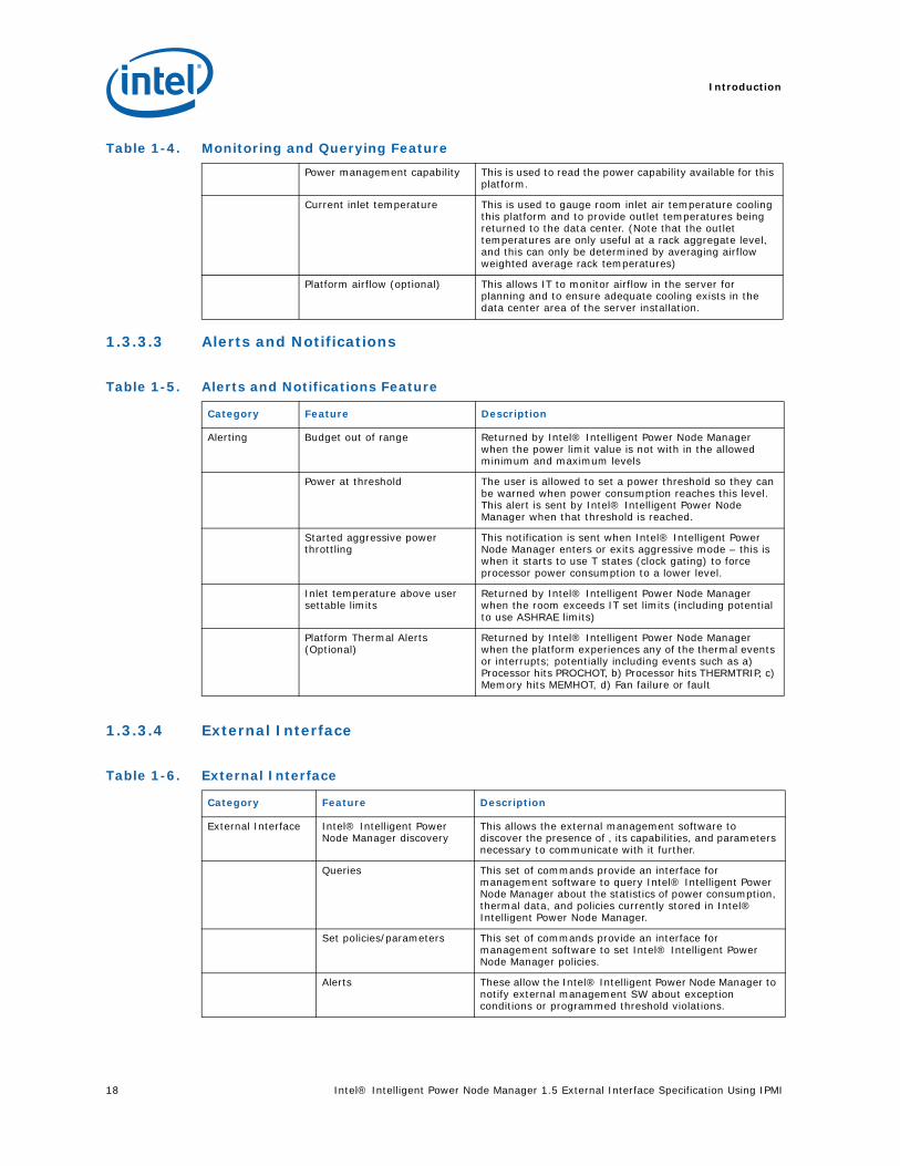
Table 1-4. Monitoring and Querying Feature
Category Feature Description
Monitoring and Querying
Platform power consumption: point in time or average over an interval
This allows IT to monitor actual power consumption either at a given point in time or as an average over a time duration. Intel® Intelligent Power Node Manager reads, calculates and returns the appropriate value in Watts. Intel® Intelligent Power Node Manager will also be able to return the Min and Max values over the time interval.
Current policy directives This is used to read the policy directives that are currently active within Intel® Intelligent Power Node Manager.
Introduction
18 Intel® Intelligent Power Node Manager 1.5 External Interface Specification Using IPMI
1.3.3.3 Alerts and Notifications
1.3.3.4 External Interface
Power management capability This is used to read the power capability available for this platform.
Current inlet temperature This is used to gauge room inlet air temperature cooling this platform and to provide outlet temperatures being returned to the data center. (Note that the outlet temperatures are only useful at a rack aggregate level, and this can only be determined by averaging airflow weighted average rack temperatures)
Platform airflow (optional) This allows IT to monitor airflow in the server for planning and to ensure adequate cooling exists in the data center area of the server installation.
Table 1-5. Alerts and Notifications Feature
Category Feature Description
Alerting Budget out of range Returned by Intel® Intelligent Power Node Manager when the power limit value is not with in the allowed minimum and maximum levels
Power at threshold The user is allowed to set a power threshold so they can be warned when power consumption reaches this level. This alert is sent by Intel® Intelligent Power Node Manager when that threshold is reached.
Started aggressive power throttling
This notification is sent when Intel® Intelligent Power Node Manager enters or exits aggressive mode – this is when it starts to use T states (clock gating) to force processor power consumption to a lower level.
Inlet temperature above user settable limits
Returned by Intel® Intelligent Power Node Manager when the room exceeds IT set limits (including potential to use ASHRAE limits)
Platform Thermal Alerts (Optional)
Returned by Intel® Intelligent Power Node Manager when the platform experiences any of the thermal events or interrupts; potentially including events such as a) Processor hits PROCHOT, b) Processor hits THERMTRIP, c) Memory hits MEMHOT, d) Fan failure or fault
Table 1-6. External Interface
Category Feature Description
External Interface Intel® Intelligent Power Node Manager discovery
This allows the external management software to discover the presence of , its capabilities, and parameters necessary to communicate with it further.
Queries This set of commands provide an interface for management software to query Intel® Intelligent Power Node Manager about the statistics of power consumption, thermal data, and policies currently stored in Intel® Intelligent Power Node Manager.
Set policies/parameters This set of commands provide an interface for management software to set Intel® Intelligent Power Node Manager policies.
Alerts These allow the Intel® Intelligent Power Node Manager to notify external management SW about exception conditions or programmed threshold violations.
Table 1-4. Monitoring and Querying Feature

Intel® Intelligent Power Node Manager 1.5 External Interface Specification Using IPMI 19
Introduction
1.3.3.5 System Architectures Supported
§
Table 1-7. Supported System Architectures
Category Feature Description
System Architecture Support
Rackmount/pedestal servers These servers have individual power supplies and the base Intel® Intelligent Power Node Manager architecture applies
Blade servers (optional) Blade servers share a common power supply and the base architecture must be modified to support blades

Introduction
20 Intel® Intelligent Power Node Manager 1.5 External Interface Specification Using IPMI
Intel® Intelligent Power Node Manager 1.5 External Interface Specification Using IPMI
Requirements on Platform Components
2 Requirements on Platform Components
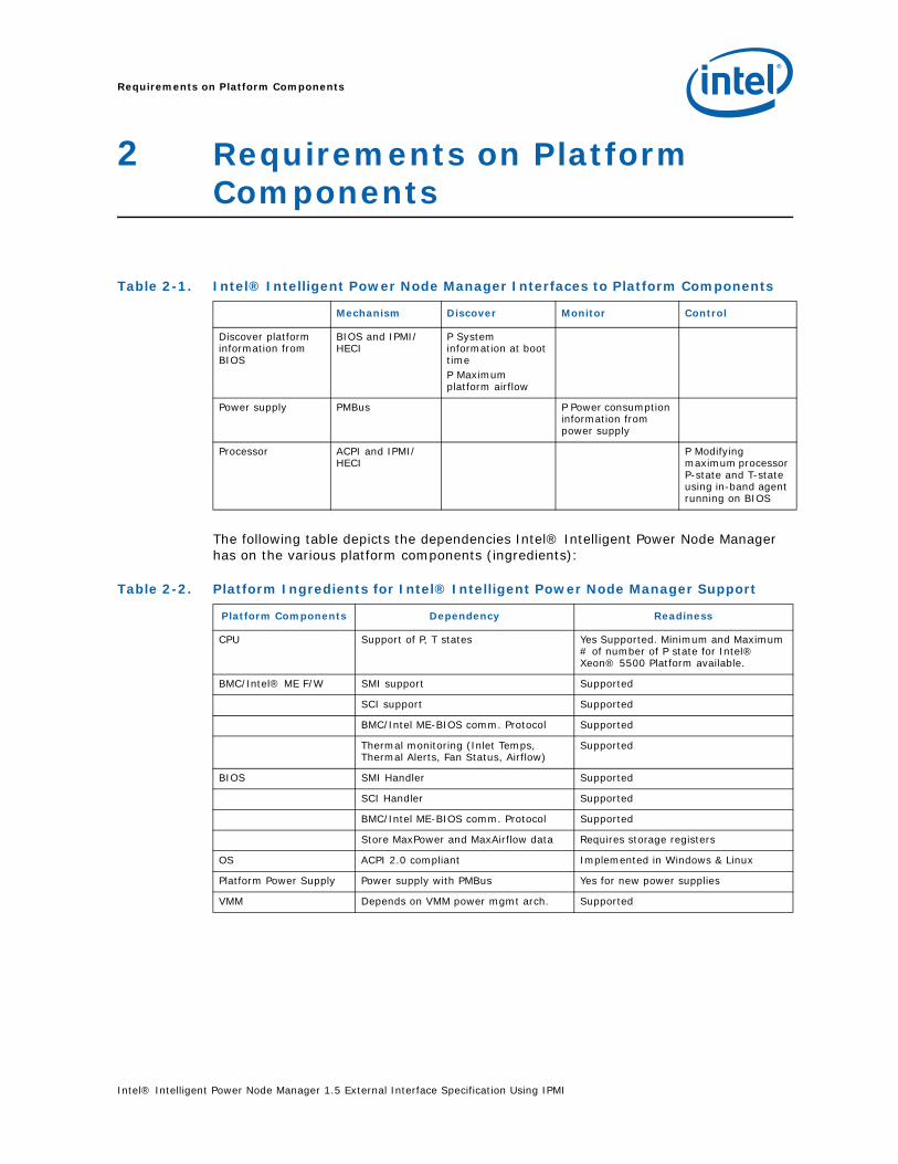
The following table depicts the dependencies Intel® Intelligent Power Node Manager has on the various platform components (ingredients):
Table 2-1. Intel® Intelligent Power Node Manager Interfaces to Platform Components
Mechanism Discover Monitor Control
Discover platform information from BIOS
BIOS and IPMI/HECI
P System information at boot timeP Maximum platform airflow
Power supply PMBus P Power consumption information from power supply
Processor ACPI and IPMI/HECI
P Modifying maximum processor P-state and T-state using in-band agent running on BIOS
Table 2-2. Platform Ingredients for Intel® Intelligent Power Node Manager Support
Platform Components Dependency Readiness
CPU Support of P, T states Yes Supported. Minimum and Maximum # of number of P state for Intel® Xeon® 5500 Platform available.
BMC/Intel® ME F/W SMI support Supported
SCI support Supported
BMC/Intel ME-BIOS comm. Protocol Supported
Thermal monitoring (Inlet Temps, Thermal Alerts, Fan Status, Airflow)
Supported
BIOS SMI Handler Supported
SCI Handler Supported
BMC/Intel ME-BIOS comm. Protocol Supported
Store MaxPower and MaxAirflow data Requires storage registers
OS ACPI 2.0 compliant Implemented in Windows & Linux
Platform Power Supply Power supply with PMBus Yes for new power supplies
VMM Depends on VMM power mgmt arch. Supported

Requirements on Platform Components
22 Intel® Intelligent Power Node Manager 1.5 External Interface Specification Using IPMI
2.1 Intel® Intelligent Power Node Manager IPMI OEM CommandsThe following table describes the IPMI commands which support Intel® Intelligent Power Node Manager. These commands a used to discover and configure Intel® Intelligent Power Node Manager and collect statistics. The commands use the IPMI Network Function Code of 2Eh, which signifies that these commands are defined by a OEM or a group other than the IPMI group.
The Intel® Intelligent Power Node Manager configuration shall be non-volatile and survive a cold-boot of the system.
There are also additional standard commands related to sensor thresholds and enabling events (listed below). These are not elaborated here since they are not Intel® Intelligent Power Node Manager-specific.
• Set Sensor Thresholds
• Get Sensor Thresholds
• Set Sensor Event Enable
• Get Sensor Event Enable
• Re-arm Sensor Events
• Get Sensor Event Status
• Get Sensor Reading
• Platform Event Message
• Alert Immediate
The following table specifies the content of the command request and response for the commands in Table 1. In the table, all reserved bits will return 0 for a Get command and should be set to 0 for a Set command.
Table 2-3. Intel® Intelligent Power Node Manager-specific OEM commands (IPMI)
Command NetFn CMD M/E1Min
PrivilegeLevel
Enable/Disable Node Manager Policy Control 2Eh C0h M Admin
Set Node Manager Policy 2Eh C1h M Admin
Get Node Manager Policy 2Eh C2h M Admin
Set Node Manager Alert Thresholds 2Eh C3h M Admin
Get Node Manager Alert Thresholds 2Eh C4h M Admin
Set Node Manager Policy Suspend Periods 2Eh C5h M Admin
Get Node Manager Policy Suspend Periods 2Eh C6h M Admin
Reset Node Manager Statistics 2Eh C7h M Admin
Get Node Manager Statistics 2Eh C8h M Admin
Get Node Manager Capabilities 2Eh C9h M Admin
Get Node Manager Version 2Eh CAh M Admin
Set Node Manager Power Draw Range 2Eh CBh M Admin
Set Node Manager Alert Destination 2Eh CEh M Admin
Get Node Manager Alert Destination 2Eh CFh M Admin
Intel® Intelligent Power Node Manager 1.5 External Interface Specification Using IPMI 23
Requirements on Platform Components
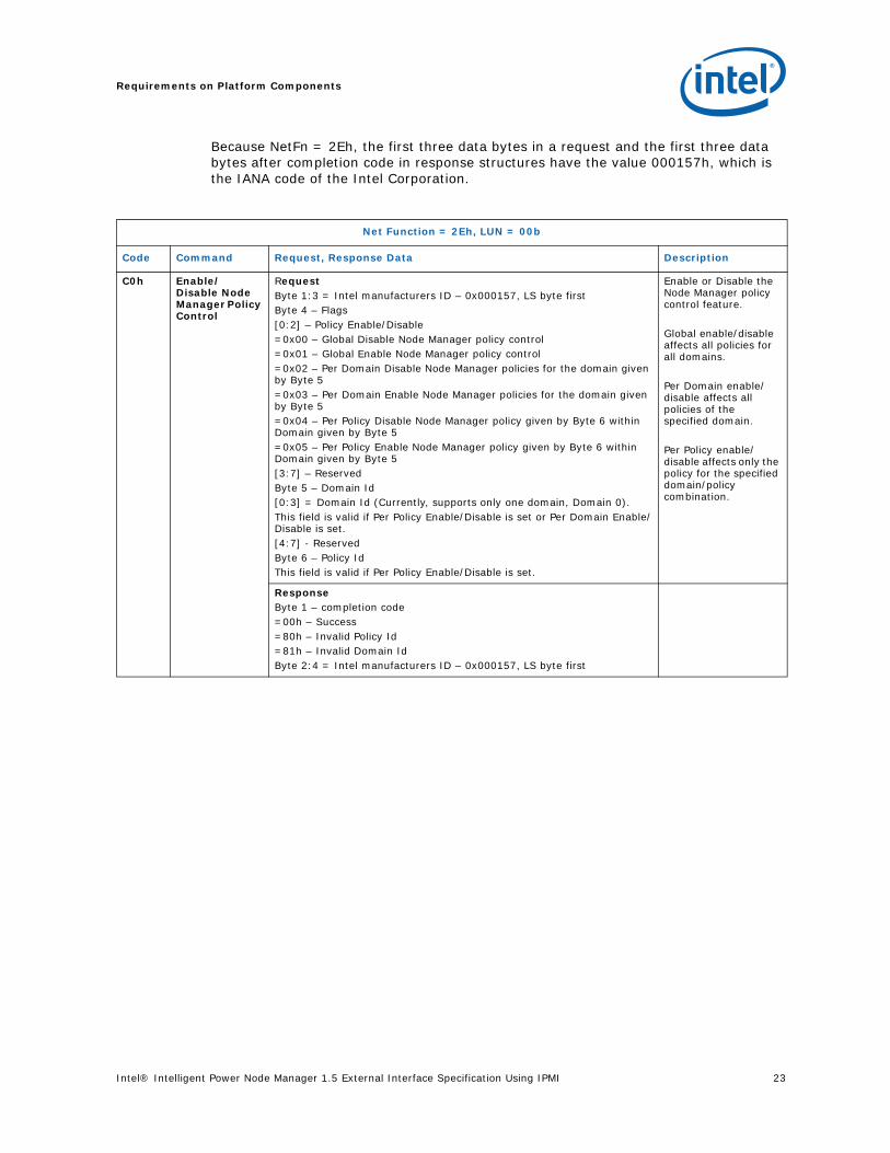
Because NetFn = 2Eh, the first three data bytes in a request and the first three data bytes after completion code in response structures have the value 000157h, which is the IANA code of the Intel Corporation.
Net Function = 2Eh, LUN = 00b
Code Command Request, Response Data Description
C0h Enable/Disable Node Manager Policy Control
RequestByte 1:3 = Intel manufacturers ID – 0x000157, LS byte firstByte 4 – Flags[0:2] – Policy Enable/Disable=0x00 – Global Disable Node Manager policy control=0x01 – Global Enable Node Manager policy control =0x02 – Per Domain Disable Node Manager policies for the domain given by Byte 5=0x03 – Per Domain Enable Node Manager policies for the domain given by Byte 5=0x04 – Per Policy Disable Node Manager policy given by Byte 6 within Domain given by Byte 5=0x05 – Per Policy Enable Node Manager policy given by Byte 6 within Domain given by Byte 5[3:7] – ReservedByte 5 – Domain Id[0:3] = Domain Id (Currently, supports only one domain, Domain 0). This field is valid if Per Policy Enable/Disable is set or Per Domain Enable/Disable is set.[4:7] - ReservedByte 6 – Policy IdThis field is valid if Per Policy Enable/Disable is set.
Enable or Disable the Node Manager policy control feature.
Global enable/disable affects all policies for all domains.
Per Domain enable/disable affects all policies of the specified domain.
Per Policy enable/disable affects only the policy for the specified domain/policy combination.
ResponseByte 1 – completion code=00h – Success=80h – Invalid Policy Id=81h – Invalid Domain IdByte 2:4 = Intel manufacturers ID – 0x000157, LS byte first

Requirements on Platform Components
24 Intel® Intelligent Power Node Manager 1.5 External Interface Specification Using IPMI
C1h Set Node Manager Policy
RequestByte 1:3 = Intel manufacturers ID – 0x000157, LS byte first
Byte 4 – Domain Id | Reserved[0:3] = Domain Id (Identifies the domain that this Node Manager policy applies to. Currently, supports only one domain, Domain 0.)[4] = Policy Enabled (set to 1 if policy should be enabled by default during policy creation/modification). Policy will be enforced (enabled and evaluated in runtime) if the corresponding Per Domain control as well as Global control is already enabled see C0h command.[5:7] = Reserved (should be set to 0)
Byte 5 – Policy Id
Byte 6 – Policy Configuration Action| Policy Trigger Type[0:3] – Policy Trigger Type=0 – No Policy Trigger, (In that case Policy Trigger Limit should be ignored)=1 – Inlet Temperature Limit Policy Trigger in [Celsius] [4:7] – Policy Configuration Action=0 - Policy Pointed by Policy Id shall be removed (remaining bytes shall be ignored on read). Corresponding (with the same Policy Id) Alert Thresholds and Suspend Periods will be removed as well.=1 - Add Power Policy. This command creates/modifies policy of type that will maintain Power limit
Byte 7 – Policy Exception Actions(if maintained policy power limit given by bytes 8-9 is exceeded over Correction Time Limit)[0] – send alert[1] – shutdown system (hard shutdown via BMC)[2:7] – reserved
Bytes 8-9 – Power Limit. This field contains power to be maintained in [Watts]
Bytes 10:13 – Correction Time Limit -The max time in ms, in which the Node Manager must take corrective actions in order to bring the platform back within the specified power limit before taking the action specified in the “Policy Exception Action” parameter.
The time is counted from the moment when the average power consumption exceeds the power limit. The average power is calculated as arithmetic moving average with the time period equal to the half of Correction Time Limit. It means that Node Manager may take the exception action after the time period equal to 1.5 of Correction Time Limit parameter starting from the moment when instantaneous power crossed the power limit.
Bytes 14:15 – Policy Trigger Limit If Byte 6 bits [0:3] is:0 – Policy Trigger Value will be ignored1 – Policy Trigger Value should define the Inlet temperature in Celsius. The value (inlet temperature of the system) as specified by trigger type will be compared against this limit and if exceeded, cause a trigger to start enforcing the Power Limit specified (Power limit will not be enforced until the trigger happens).Bytes 16:17 – Statistics Reporting Period in seconds. The number of seconds that the measured power will be averaged over for the purpose of reporting statistics to external management SW. This is a moving window. Note that this value is different from the period that Node Manager uses for maintaining an average for the purpose of power control.
User can specify any valid PolicyId. If already existing, this command will overwrite/modify the parameters for the existing policy, otherwise a new policy will be created with this policy Id. Modification is possible only if that policy for the specified PolicyId is disabled.Note: The operator may define a special kind of Inlet Air Temperature policy called Minimum Power Consumption policy with the Power Limit set to 0. The policy does not have the power limit defined. When the inlet air temperature raises above the trigger value defined in the policy, the SPS firmware reduces the power consumption to minimum by requesting OSPM or SMM to set minimum P-state and T-state. The Minimum Power Consumption policy does not allow setting the correction action to “System Shutdown”, but the operator can specify whether the SPS firmware shall minimize power consumption by only reducing P-state or the firmware shall use both P-state and T-state
Net Function = 2Eh, LUN = 00b
Code Command Request, Response Data Description

Intel® Intelligent Power Node Manager 1.5 External Interface Specification Using IPMI 25
Requirements on Platform Components
ResponseByte 1 – completion code=00h – Success =80h – Invalid Policy Id=81h – Invalid Domain Id =82h – unknown or unsupported Policy Trigger Type=83h – unknown or unsupported Policy Configuration Action=84h – Power Limit out of range=85h – Correction Time out of range=86h – Policy Trigger value out of range=89h – Statistics Reporting Period out of range=D5h – Policy could not be updated since PolicyId already exists and is enabled.Byte 2:4 = Intel manufacturers ID – 0x000157, LS byte first
Net Function = 2Eh, LUN = 00b
Code Command Request, Response Data Description

Requirements on Platform Components
26 Intel® Intelligent Power Node Manager 1.5 External Interface Specification Using IPMI
C2h Get Node Manager Policy
RequestByte 1:3 = Intel manufacturers ID – 0x000157, LS byte firstByte 4 – Domain Id [0:3] = Domain Id (Currently, supports only one domain, Domain 0)[4:7] = Reserved (should be set to 0)Byte 5 – Policy Id
Gets the Node Manager policy parameters.
ResponseByte 1 -- completion code=00h – Success =80h – Invalid Policy Id=81h – Invalid Domain IdByte 2:4 = Intel manufacturers ID – 0x000157, LS byte firstByte 5 – Domain Id | Policy state | Reserved[0:3] = Domain Id (Identifies the domain that this Node Manager policy applies to. Default is ‘0000b’. Currently, supports only one domain, Domain 0.)[4] = Policy enabled[5] = per Domain Node Manager policy control enabled[6] = Global Node Manager policy control enabled[7] = Reserved (should be set to 0)Byte 6 – Policy Type | Policy Trigger Type[0:3] – Policy Trigger Type=0 – No Policy Trigger, Policy will maintain Power limit (In that case Policy Trigger Value will be equal to the Power Limit)=1 – Inlet Temperature Limit Policy Trigger in [Celsius][4:7] – Policy Type=1 - Power Control PolicyByte 7 – Policy Exception Actions(if maintained policy power limit given by bytes 8-9 is exceeded over Correction Time Limit)[1] – shutdown system[0] – send alert [2:7] – reserved
Bytes 8-9 – Power Limit. This field contains power to be maintained in [Watts]Bytes 10:13 – Correction Time Limit - the max time in ms, in which Node Manager must take corrective actions in order to bring the platform back within the specified power limit before taking the action specified in the “Policy Exception Action” parameter.The time is counted from the moment when the average power consumption exceeds the power limit. The average power is calculated as arithmetic moving average with the time period equal to the half of Correction Time Limit. It means that Node Manager may take the exception action after the time period equal to 1.5 of Correction Time Limit parameter starting from the moment when instantaneous power crossed the power limit.Bytes 14:15 – Policy Trigger Limit The value (inlet temperature of the system) as specified by trigger type will be compared against this limit and if exceeded, cause a trigger to start enforcing the Power Limit specified (Power limit will not be enforced until the trigger happens).If Byte 6 bits [0:3] is 0 this field contains the same value as Power Limit (that is, it does not contain the trigger value passed to Node Manager using Set Node Manager Policy).
Bytes 16:17 – Statistics Reporting Period The number of seconds that the measured power will be averaged over for the purpose of reporting statistics to external management SW. This is a moving window. Note that this value is different from the period that Node Manager uses for maintaining an average for the purpose of power control.
Net Function = 2Eh, LUN = 00b
Code Command Request, Response Data Description

Intel® Intelligent Power Node Manager 1.5 External Interface Specification Using IPMI 27
Requirements on Platform Components
C3h Set Node Manager Alert Thresholds
RequestByte 1:3 = Intel manufacturers ID – 0x000157, LS byte firstByte 4 – Domain Id[0:3] = Domain Id (Currently, supports only one domain, Domain 0.)[4:7] = Reserved (should be set to 0)Byte 5 – Policy IdByte 6 – Number of alert thresholdsBytes 7:N – Alert threshold array (the array length is based on the number of thresholds given in the byte 6). Node Manager will generate the event if the average power or temperature based on the policy trigger (computed over an averaging period derived based on correction time limit) exceeds any of the configured alert thresholds. (assert for exceeding (going high) and desertion for going low). The hysteresis value for avoiding jitters around the threshold will be OEM configurable using factory-preset values.Note: Max 3 alert thresholds are supported per policy. Each alert threshold is 2 bytes in length (LSB first). If number of alert thresholds is 0 then the previously set alert thresholds (if present) are removed from the policy. Alert thresholds shall be provided in units defined for trigger in given Policy Id [Celsius] (or [Watts] for policy without trigger)
Sets the Node Manager alert thresholds. This is part of the Node Manager Policy described earlier and applies to the same policy as specified by PolicyId.
ResponseByte 1 — completion code=00h – Success =80h – Invalid Policy Id=81h – Invalid Domain Id=84h – Limit in one of thresholds is invalid =87h – Invalid Number of Policy Thresholds=D5h – Alert thresholds can not be changed for enabled policy, disable it firstByte 2:4 = Intel manufacturers ID – 0x000157, LS byte first
Net Function = 2Eh, LUN = 00b
Code Command Request, Response Data Description

Requirements on Platform Components
28 Intel® Intelligent Power Node Manager 1.5 External Interface Specification Using IPMI
C4h Get Node Manager Alert Thresholds
RequestByte 1:3 = Intel manufacturers ID – 0x000157, LS byte firstByte 4 – Domain Id[0:3] = Domain Id (Currently, supports only one domain, Domain 0)[4:7] = Reserved (should be set to 0)Byte 5 – Policy Id
Gets the Node Manager alert thresholds
ResponseByte 1 – completion code=00h – Success =80h – Invalid Policy Id=81h – Invalid Domain Id Byte 2:4 = Intel manufacturers ID – 0x000157, LS byte firstByte 5 – Number of alert thresholdsBytes 6:N – Alert threshold array (the array length is based on the number of threshold given in the byte 5)). If number of alert thresholds is 0 then the array length is 0 bytes.Note: Max 3 alert thresholds are supported per policy. Each alert threshold is 2 bytes in length (LSB first). Alert thresholds are provided in units defined for trigger in given Policy Id [Celsius] (or [Watts] for policy without trigger).
Net Function = 2Eh, LUN = 00b
Code Command Request, Response Data Description

Intel® Intelligent Power Node Manager 1.5 External Interface Specification Using IPMI 29
Requirements on Platform Components
C5h Set Node Manager Policy Suspend Periods
Request:Byte 1:3 = Intel manufacturers ID – 0x000157, LS byte firstByte 4 – Domain Id[0:3] = Domain Id (Currently, supports only one domain, Domain 0)[4:7] = Reserved (should be set to 0)Byte 5 – Policy IdByte 6 – Number of policy suspend periods. This value should be specified as 0 if all the suspend periods are to be removed (if previously set).Bytes 7:N – array of policy suspend periods (following information is repeated for each suspend period). Each suspend period is defined by 3 bytes:1st byte – Policy suspend start time =0 – 239 number of minutes from mid-night divided by 6= 240 – 255 reserved2nd byte – Policy suspend stop time = 0 reserved=1 – 240 number of minutes from mid-night divided by 6= 241 – 255 reserved3rd byte – Suspend period recurrence pattern:[0] – repeat the suspend period every Monday[1] – repeat the suspend period every Tuesday[2] – repeat the suspend period every Wednesday[3] – repeat the suspend period every Thursday[4] – repeat the suspend period every Friday[5] – repeat the suspend period every Saturday[6] – repeat the suspend period every Sunday[7] – reserved. Write as 0bNote: Policy suspend start and stop time is 1 byte in length each. Max 5 suspend periods can be specified per policy. If the number of policy suspend period (that is, byte 6) is 0 then the rest of the bytes in the request message are not required and previously configured suspend periods are removed from the system for the specified policy Id.The suspend periods are specified as an array. For example, if policy suspend start time is in byte 7 then byte 8 will contain the policy suspend stop time and byte 9 will contain suspend period recurrence pattern. Similarly, if the 2nd set of suspend periods are to be specified then they will be present in bytes 10:12.The suspend times are encoded on one byte each as number of minutes from mid-night divided by 6 to fit into one byte. If there is a need to specify an end-time that is beyond midnight, use two suspend periods, one ending at midnight (suspend stop time byte set to 240) and one from midnight (suspend start time set to 0) until the necessary end-time of the next day.
Sets the Node Manager policy suspend period (during which no platform power policy control will be enforced)
ResponseByte 1 – completion code=00h – Success =80h – Invalid Policy Id=81h – Invalid Domain Id =85h – One of periods in the table is inconsistent. Start time is greater than or equal to stop time or stop time sets time beyond 1 day=87h – Invalid Number of policy suspend periods =D5h – Suspend periods can not be changed for enabled policy, disable it first.Byte 2:4 = Intel manufacturers ID – 0x000157, LS byte first
Net Function = 2Eh, LUN = 00b
Code Command Request, Response Data Description

Requirements on Platform Components
30 Intel® Intelligent Power Node Manager 1.5 External Interface Specification Using IPMI
C6h Get Node Manager Policy Suspend Periods
RequestByte 1:3 = Intel manufacturers ID – 0x000157, LS byte firstByte 4 – Domain Id[0:3] = Domain Id (Currently, supports only one domain, Domain 0)[4:7] = Reserved (should be set to 0)Byte 5 – Policy Id
Get the Node Manager suspend periods
ResponseByte 1 – completion code=00h – Success=80h – Invalid Policy Id=81h – Invalid Domain IdByte 2:4 = Intel manufacturers ID – 0x000157, LS byte firstByte 5 – Number of policy suspend periodsBytes 6:N – array of suspend periodsEach suspend period is defined by 3 bytes:1st byte – Policy suspend start time encoded as a number of minutes from mid-night divided by 62nd byte – Policy suspend stop time encoded as a number of minutes from mid-night divided by 63rd byte – Suspend period recurrence pattern:[7] – reserved. Write as 0b[6] – repeat the suspend period every Sunday[5] – repeat the suspend period every Saturday[4] – repeat the suspend period every Friday[3] – repeat the suspend period every Thursday[2] – repeat the suspend period every Wednesday[1] – repeat the suspend period every Tuesday[0] – repeat the suspend period every MondayNote: If byte 5 is 0x00 then no subsequent bytes will be present in the response. This means there are no suspend periods configured for the specified policy Id.Note: The suspend periods are specified as an array. For example, if 1st suspend period is in bytes 6:8 then bytes 9:11 will contain the 2nd policy suspend period.
C7h Reset Node Manager Statistics
RequestByte 1:3 = Intel manufacturers ID – 0x000157, LS byte firstByte 4 – Mode[0:4] -Mode=0x00 – reset global statistics including power statistics and inlet temperature statistics=0x01 – per policy statistics including power and trigger statistics [5:7]– ReservedByte 5 – Domain Id[0:3] = Domain Id (Currently, FW supports only one domain, Domain 0)[4:7] = Reserved (should be set to 0)Byte 6 – Policy Id (ignored if in Byte 4 field Mode is set to 0x00)
Set the Node Manager Power Statistics
ResponseByte 1 – Completion code=00h – Success=80h – Invalid Policy Id=81h – Invalid Domain Id=88h – Invalid ModeByte 2:4 = Intel manufacturers ID – 0x000157, LS byte first
Net Function = 2Eh, LUN = 00b
Code Command Request, Response Data Description

Intel® Intelligent Power Node Manager 1.5 External Interface Specification Using IPMI 31
Requirements on Platform Components
C8h Get Node Manager Statistics
RequestByte 1:3 = Intel manufacturers ID – 0x000157, LS byte firstByte 4 –Mode[0:4] – Mode=0x01 – global power statistics in [Watts]=0x02 – global inlet temperature statistics in [Celsius]=0x03 – Reserved=0x04 – Reserved=0x11 – per policy power statistics in [Watts]=0x12 – per policy trigger statistics in [Celsius][5:7] – ReservedByte 5 – Domain Id[0:3] = Domain Id (Currently, FW supports only one domain, Domain 0)[4:7] = Reserved (should be set to 0)Byte 6 – Policy Id (not ignored if Byte 1 == 0x11 or Byte 1 == 0x12)
Get the Node Manager Power StatisticsNote that the average values provided here may be different from the averaged values used by Node Manager for taking corrective action or triggering alerts based a ‘Set Node Manager Alert Threshold’ because the averaging period for the two could be different.
Net Function = 2Eh, LUN = 00b
Code Command Request, Response Data Description
Requirements on Platform Components
32 Intel® Intelligent Power Node Manager 1.5 External Interface Specification Using IPMI
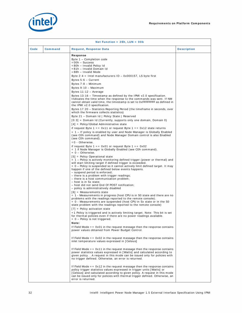
ResponseByte 1 – Completion code=00h – Success =80h – Invalid Policy Id=81h – Invalid Domain Id=88h – Invalid Mode Byte 2:4 = Intel manufacturers ID – 0x000157, LS byte firstBytes 5:6 – CurrentBytes 7:8 – MinimumBytes 9:10 – MaximumBytes 11:12 – AverageBytes 13:16 – Timestamp as defined by the IPMI v2.0 specification. Indicates the time when the response to the commands was sent. If NM cannot obtain valid time, the timestamp is set to 0xFFFFFFFF as defined in the IPMI v2.0 specification.Bytes 17:20 – Statistics Reporting Period (the timeframe in seconds, over which the firmware collects statistics)Byte 21 – Domain Id | Policy State | Reserved[0:3] = Domain Id (Currently, supports only one domain, Domain 0)[4] = Policy/Global Administrative state if request Byte 1 == 0x11 or request Byte 1 == 0x12 state returns= 1 – If policy is enabled by user and Node Manager is Globally Enabled (see C0h command) and Node Manager Domain control is also Enabled (see C0h command).=0 - Otherwise.if request Byte 1 == 0x01 or request Byte 1 == 0x02= 1 if Node Manager is Globally Enabled (see C0h command).= 0 – Otherwise.[5] = Policy Operational state= 1 – Policy is actively monitoring defined trigger (power or thermal) and will start limiting target if defined trigger is exceeded.= 0 – Policy is suspended so it cannot actively limit defined target. It may happen if one of the defined below events happens. – suspend period is enforced; – there is a problem with trigger readings;– there is a host communication problem; – host is in Sx state;– host did not send End Of POST notification;– policy is administratively disabled [6] = Measurements state= 1 - Measurements in progress (host CPU is in S0 state and there are no problems with the readings reported to the remote console). = 0 - Measurements are suspended (host CPU in Sx state or in the S0 state problem with the readings reported to the remote console)[7] = Policy activation state=1 Policy is triggered and is actively limiting target. Note: This bit is set for thermal policies even if there are no power readings available.= 0 – Policy is not triggered. Note: If Field Mode == 0x01 in the request message then the response contains power values obtained from Power Budget Control.
If Field Mode == 0x02 in the request message then the response contains inlet temperature values expressed in [Celsius]
If Field Mode == 0x11 in the request message then the response contains power statistics values expressed in [Watts] and calculated according to given policy. . A request in this mode can be issued only for policies with no trigger defined. Otherwise, an error is returned.
If Field Mode == 0x12 in the request message then the response contains policy trigger statistics values expressed in trigger units [Watts] or [Celsius] and calculated according to given policy. A request in this mode can be issued only for policies with thermal trigger defined. Otherwise, an error is returned.
Net Function = 2Eh, LUN = 00b
Code Command Request, Response Data Description
Intel® Intelligent Power Node Manager 1.5 External Interface Specification Using IPMI 33
Requirements on Platform Components
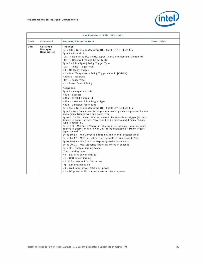
C9h Get NodeManager Capabilities
RequestByte 1:3 = Intel manufacturers ID – 0x000157, LS byte firstByte 4 – Domain Id[0:3] = Domain Id (Currently, supports only one domain, Domain 0)[4:7] = Reserved (should be set to 0)Byte 5 –Policy Type | Policy Trigger Type[0:3] – Policy Trigger Type =0 – No Policy Trigger,=1 – Inlet Temperature Policy Trigger value in [Celsius]=others – reserved [4:7] – Policy Type=1 - Power Control Policy
ResponseByte 1 – completion code=00h – Success=81h – Invalid Domain Id=82h – unknown Policy Trigger Type=83h – unknown Policy TypeByte 2:4 = Intel manufacturers ID – 0x000157, LS byte firstByte 5 – Max Concurrent Settings – number of policies supported for the given policy trigger type and policy type.Bytes 6:7 – Max Power/Thermal value to be settable as trigger (in units defined in query) or max Power Limit to be maintained if Policy Trigger Type is equal to 0Bytes 8:9 – Min Power/Thermal value to be settable as trigger (in units defined in query) or min Power Limit to be maintained if Policy Trigger Type is equal to 0Bytes 10:13 – Min Correction Time settable in milli-seconds (ms)Bytes 14:17 – Max Correction Time settable in milli-seconds (ms)Bytes 18-19 – Min Statistics Reporting Period in secondsBytes 20-21 – Max Statistics Reporting Period in secondsByte 22 – Domain limiting scope[0:6] Limiting type=0 – platform power limiting=1 – CPU power limiting=2..127 - reserved for future use[7] – Limiting based on=0 – Wall input power. PSU input power =1 – DC power – PSU output power or bladed system
Net Function = 2Eh, LUN = 00b
Code Command Request, Response Data Description
Requirements on Platform Components
34 Intel® Intelligent Power Node Manager 1.5 External Interface Specification Using IPMI
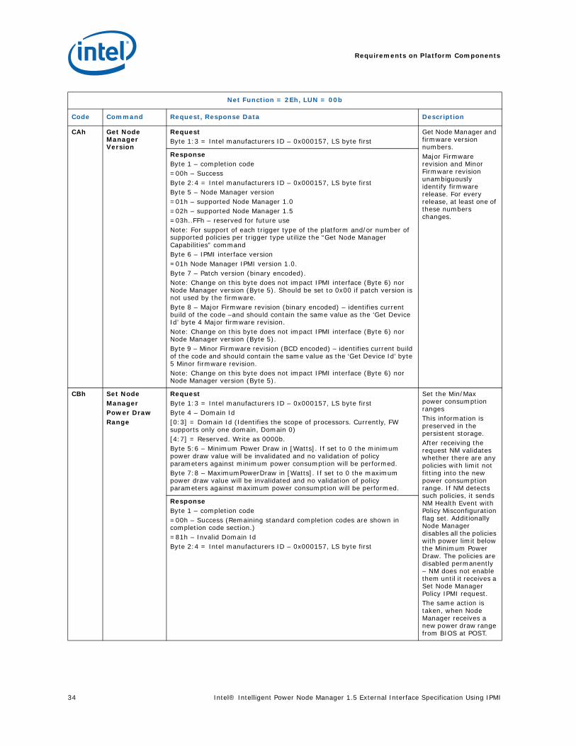
CAh Get Node Manager Version
RequestByte 1:3 = Intel manufacturers ID – 0x000157, LS byte first
Get Node Manager and firmware version numbers.Major Firmware revision and Minor Firmware revision unambiguously identify firmware release. For every release, at least one of these numbers changes.
ResponseByte 1 – completion code=00h – Success Byte 2:4 = Intel manufacturers ID – 0x000157, LS byte firstByte 5 – Node Manager version=01h – supported Node Manager 1.0 =02h – supported Node Manager 1.5=03h..FFh – reserved for future useNote: For support of each trigger type of the platform and/or number of supported policies per trigger type utilize the “Get Node Manager Capabilities” commandByte 6 – IPMI interface version=01h Node Manager IPMI version 1.0. Byte 7 – Patch version (binary encoded).Note: Change on this byte does not impact IPMI interface (Byte 6) nor Node Manager version (Byte 5). Should be set to 0x00 if patch version is not used by the firmware.Byte 8 – Major Firmware revision (binary encoded) – identifies current build of the code –and should contain the same value as the ‘Get Device Id’ byte 4 Major firmware revision. Note: Change on this byte does not impact IPMI interface (Byte 6) nor Node Manager version (Byte 5).Byte 9 – Minor Firmware revision (BCD encoded) – identifies current build of the code and should contain the same value as the ‘Get Device Id’ byte 5 Minor firmware revision. Note: Change on this byte does not impact IPMI interface (Byte 6) nor Node Manager version (Byte 5).
CBh Set Node Manager Power DrawRange
RequestByte 1:3 = Intel manufacturers ID – 0x000157, LS byte firstByte 4 – Domain Id[0:3] = Domain Id (Identifies the scope of processors. Currently, FW supports only one domain, Domain 0)[4:7] = Reserved. Write as 0000b.Byte 5:6 – Minimum Power Draw in [Watts]. If set to 0 the minimum power draw value will be invalidated and no validation of policy parameters against minimum power consumption will be performed. Byte 7:8 – MaximumPowerDraw in [Watts]. If set to 0 the maximum power draw value will be invalidated and no validation of policy parameters against maximum power consumption will be performed.
Set the Min/Max power consumption rangesThis information is preserved in the persistent storage.After receiving the request NM validates whether there are any policies with limit not fitting into the new power consumption range. If NM detects such policies, it sends NM Health Event with Policy Misconfiguration flag set. Additionally Node Manager disables all the policies with power limit below the Minimum Power Draw. The policies are disabled permanently – NM does not enable them until it receives a Set Node Manager Policy IPMI request.The same action is taken, when Node Manager receives a new power draw range from BIOS at POST.
ResponseByte 1 – completion code=00h – Success (Remaining standard completion codes are shown in completion code section.)=81h – Invalid Domain IdByte 2:4 = Intel manufacturers ID – 0x000157, LS byte first
Net Function = 2Eh, LUN = 00b
Code Command Request, Response Data Description

Intel® Intelligent Power Node Manager 1.5 External Interface Specification Using IPMI 35
Requirements on Platform Components
CEh Set Node Manager Alert Destination
RequestByte 1:3 = Intel manufacturers ID – 0x000157, LS byte firstByte 4 – Channel number[0:3] – BMC channel number over which to send the alert from BMC to management console. Alerts can be sent to only one console.[4:6] -reserved[7] – destination information operation0 – register alert receiver 1 – unregister alert receiver. Use this bit to invalidate the current destination configuration. Alerts will be blocked.
Byte 5 – Destination InformationFor channel medium = IPMB[0] – reserved [1:7] - 7-bit I2C Slave Address For channel medium = 802.3 LANDestination Selector/ Operation[0:3] - destination selector. Selects which alert destination should go to.0h = use volatile destination info. 1h-Fh = non-volatile destination.Destination Selector definition is the same as in the « Set/Get LAN Configuration Parameters » command.[4:7] – reserved
Byte 6 - Alert String SelectorSelects which Alert String, if any, to use with the alert.[0:6] - string selector.0000_0000b = use volatile Alert String.01h-7Fh = non-volatile string selector.Alert String Selector definition is the same as in the « Set/Get PEF Configuration Parameters » command.[7] -0b = don’t send an Alert String1b = send Alert String identified by following string selector.
Provide alert destination information for Intel® Intelligent Power Node Manager to send direct alerts that bypass the BMC SEL.
Destination Selector/Operation and Alert String Selector fields correspond to the associated LAN configuration parameters applicable to the BMC channel number over which to send the alert
Note that the NM will determine the channel medium type in order to resolve the destination. If NM is implemented in an entity separate from the BMC, then this is done by querying the BMC using the Get Channel Info IPMI command.
ResponseByte 1 – completion code=00h – Success Byte 2:4 = Intel manufacturers ID – 0x000157, LS byte first
Net Function = 2Eh, LUN = 00b
Code Command Request, Response Data Description

Requirements on Platform Components
36 Intel® Intelligent Power Node Manager 1.5 External Interface Specification Using IPMI
CFh Get Node Manager Alert Destination
RequestByte 1:3 = Intel manufacturers ID – 0x000157, LS byte first
Provides alert destination information that is used to send alerts from Intel® Intelligent Power Node Manager.
ResponseByte 1 – completion code=00h – Success Byte 2:4 = Intel manufacturers ID – 0x000157, LS byte firstByte 5 – Channel number[0:3] – BMC channel number over which alert from BMC to management console will be sent[4:6] -–reserved[7] –Destination information operation0 – configuration valid. Alert receiver registered.1- configuration invalid. Alert receiver not registered. Alerts are blocked.
Byte 6 - Destination Selector/ Operation[0:3] -destination selector. Selects which alert destination should go to.0h = use volatile destination info. 1h-Fh = non-volatile destination.
[4:7] - reserved
Byte 7 - Alert String SelectorSelects which Alert String, if any, to use with the alert.[0:6] - string selector.0000_0000b = use volatile Alert String. 01h-7Fh = non-volatile string selector.[7] -0b = don’t send an Alert String1b = send Alert String identified by following string selector.
Net Function = 2Eh, LUN = 00b
Code Command Request, Response Data Description

Intel® Intelligent Power Node Manager 1.5 External Interface Specification Using IPMI 37
Requirements on Platform Components
2.2 IPMI SensorsThe following IPMI sensors are supported by Intel® Intelligent Power Node Manager. The values are encoded as described by the special encoding rules described in the Appendix.
2.3 IPMI EventsThe following are Intel® Intelligent Power Node Manager-specific events that are exposed via IPMI.
Table 2-4. Intel® Intelligent Power Node Manager IPMI Sensors
Description Sensor Number
Reading Availability Notes
Node manager exception event sensor
See SDR Section 2.6
Event-only OEM Event only sensor used to send events when Intel® Intelligent Power Node Manager detects that power budget could not be maintained. “Command illegal for specified sensor or record type (CDh)” error code is returned in response to the following commands: Get Sensor Reading, Set/Get Sensor Thresholds, Re-Arm Sensor Events, Set/Get Sensor Event Enable.
Node Manager Health event sensor
See SDR Section 2.6
Event-only OEM Event only sensor used to send events about integrity of Intel® Intelligent Power Node Manager policy or necessary sensor readings.“Command illegal for specified sensor or record type (CDh)” error code is returned in response to the following commands: Get Sensor Reading, Set/Get Sensor Thresholds, Re-Arm Sensor Events, Set/Get Sensor Event Enable.
Node Manager Operational Capabilities sensor
See SDR Section 2.6
Read, Event OEM sensor, whose value will indicate the operational capabilities of the sensor. Whenever the sensor value changes, an immediate alert is also sent. Please see the event description for the description of the values of the sensor.
Node Manager Alert Threshold Exceeded sensor
See SDR Section 2.6
Event-only OEM Event only sensor used to send events when Intel® Intelligent Power Node Manager detects that a specified alert threshold for one of the policies is exceeded. “Command illegal for specified sensor or record type (CDh)” error code is returned in response to the following commands: Get Sensor Reading, Set/Get Sensor Thresholds, Re-Arm Sensor Events, Set/Get Sensor Event Enable.
Table 2-5. Intel® Intelligent Power Node Manager IPMI Events
Event Sensor Type Event Dir Event Type ImmediateAlert
Node Manager Exception Event DCh – OEM 0 – assertion 72h – OEM No
Node Manager Health Event DCh – OEM 0 – assertion 73h – OEM Yes
Node Manager Operational Capabilities Change Event
DCh – OEM 0 – assertion1 – deassertion
74h – OEM Yes
Node Manager Alert Threshold Exceeded DCh – OEM 0 – assertion
1 – deassertion
72h – OEM Yes

Requirements on Platform Components
38 Intel® Intelligent Power Node Manager 1.5 External Interface Specification Using IPMI
Net Function = S/E (0x4), LUN = 00b
Code Command Request, Response Data Description
02h Platform Event MessageNode Manager Exception Event
Request Byte 1 - EvMRev=04h (IPMI2.0 format)Byte 2 – Sensor Type=DCh (OEM)Byte 3 – Sensor Number= See SDR Section 2.6 – Node Manager event SensorByte 4 – Event Dir | Event Type[0:6] – Event Type=72h (OEM) [7] – Event Dir=0 Assertion Event=1 Deassertion Event
Byte 5 – Event Data 1[0:1] – Return as 00b[2] – Reserved[3] = Node Manager Policy event0 – Reserved 1 – Policy Correction Time Exceeded – policy did not meet the contract for the defined policy. The policy will continue to limit the power or shutdown the platform based on the defined policy action.[4:5]=10b – OEM code in byte 3[6:7]=10b – OEM code in byte 2Byte 6 – Event Data 2[0:3] – Domain Id (Currently, supports only one domain, Domain 0)[4:7] – ReservedByte 7 – Event Data 3=<Policy Id>.
Event will be sent each time when maintained policy power limit is exceeded over Correction Time Limit. First occurrence of not acknowledged event will be retransmitted no faster
than every 300 milliseconds
ResponseByte 1 completion code=00h – Successothers – Error

Intel® Intelligent Power Node Manager 1.5 External Interface Specification Using IPMI 39
Requirements on Platform Components
02h Alert Immediate MessageNode Manager Health Event
Request Byte 1 - EvMRev=04h (IPMI2.0 format)Byte 2 – Sensor Type=DCh (OEM)Byte 3 – Sensor Number= See SDR Section 2.6 – Node Manager Health sensorByte 4 – Event Dir | Event Type[0:6] – Event Type= 73h (OEM)[7] – Event Dir=0 Assertion Event
Byte 5 – Event Data 1[0:3] – Health Event Type=02h – Sensor Node Manager[4:5]=10b – OEM code in byte 3[6:7]=10b – OEM code in byte 2
Byte 6 – Event Data 2[0:3] – Domain Id (Currently, supports only one domain, Domain 0)[4:7] – Error type=0-9 - Reserved=10 – Policy Misconfiguration=11 – Power Sensor Reading Failure=12 – Inlet Temperature Reading Failure=13 – Host Communication error=14 – Real-time clock synchronization failure=15 – Platform shutdown initiated by NM policy due to execution of action defined by Policy Exception Action see “Set NM Policy” command Byte 7 bit [1]=16 – Reserved Byte 7 – Event Data 3if error indication = 10 or 15 <PolicyId>if error indication = 11 <PowerSensorAddress>if error indication = 12 <InletSensorAddress>Otherwise set to 0.
This message provides a run-time error indication about Intel® Intelligent Power Node Manager’s health. Types of service that can send an error are defined as follows:Misconfigured policy Error reading power data Error reading inlet temp.Note: Misconfigured policy can happen if the max/min power consumption of the platform exceeds the values in policy due to hardware reconfiguration.First occurrence of not acknowledged event will be retransmitted no faster than every 300 milliseconds.Real-time clock synchronization failure alert is sent when NM is enabled and capable of limiting power, but within 10 minutes the firmware can not obtain valid calendar time from the host side, so NM can not handle suspend periods.
ResponseByte 1 completion code=00h – Successothers – Error
Net Function = S/E (0x4), LUN = 00b
Code Command Request, Response Data Description

Requirements on Platform Components
40 Intel® Intelligent Power Node Manager 1.5 External Interface Specification Using IPMI
Net Function = S/E (0x4), LUN = 00b
Code Command Request, Response Data Description
02h Alert Immediate MessageNode Manager Operational Capabilities Change
Request Byte 1 - EvMRev=04h (IPMI2.0 format)Byte 2 – Sensor Type=DCh (OEM)Byte 3 – Sensor Number= See SDR Section 2.6–– Node Manager Operational Capabilities sensorByte 4 – Event Dir | Event Type[0:6] – Event Type= 74h (OEM)[7] – Event Dir=0 Assertion Event=1 Deassertion Event
Byte 5 – Event Data 1[0:3] – Current state of Operational Capabilities The same value is also returned by the Get Sensor Reading command invoked for Operational Capabilities sensor.Bit pattern:0 – Policy interface capabilityValue 0 - Not AvailableValue 1 - Available1 – Monitoring capabilityValue 0 - Not AvailableValue 1 - Available2 – Power limiting capabilityValue 0 - Not AvailableValue 1 - Available [4:7]=Reserved
This message provides a run-time error indication about Intel® Intelligent Power Node Manager’s operational capabilities. This applies to all domains.Assertion and deassertion of these events are supported.Policy Interface available indicates that Intel® Intelligent Power Node Manager is able to respond to the external interface about querying and setting Intel® Intelligent Power Node Manager policies. This is generally available as soon as the microcontroller is initialized.Monitoring Interface available indicates that Intel® Intelligent Power Node Manager has the capability to monitor power and temperature. This is generally available when firmware is operational.Power limiting interface available indicates that Intel® Intelligent Power Node Manager can do power limiting and is indicative of an ACPI-compliant OS loaded (unless the OEM has indicated support for non-ACPI-compliant OS).Current value of not acknowledged capability sensor will be retransmitted
no faster than every 300 milliseconds
ResponseByte 1 completion code=00h – Successothers – Error

Intel® Intelligent Power Node Manager 1.5 External Interface Specification Using IPMI 41
Requirements on Platform Components
Net Function = S/E (0x4), LUN = 00b
Code Command Request, Response Data Description
02h Alert Immediate MessageNode manager Alert Threshold Exceeded
Request Byte 1 - EvMRev=04h (IPMI2.0 format)Byte 2 – Sensor Type=DCh (OEM)Byte 3 – Sensor Number=See SDR Section 2.6 – Node Manager Alert Threshold Exceeded event SensorByte 4 – Event Dir | Event Type[0:6] – Event Type=72h (OEM) [7] – Event Dir=0 Assertion Event=1 Deassertion Event
Byte 5 – Event Data 1[0:1] – Threshold Number. valid only if Byte 5 bit [3] is set to 00 to 2 – threshold index[2] – Reserved[3] = Node Manager Policy event0 –Threshold exceeded1 – Policy Correction Time Exceeded – policy did not meet the contract for the defined policy. The policy will continue to limit the power or shutdown the platform based on the defined policy action.
[4:5]=10b – OEM code in byte 3[6:7]=10b – OEM code in byte 2Byte 6 – Event Data 2[0:3] – Domain Id (Currently, supports only one domain, Domain 0)[4:7] – ReservedByte 7 – Event Data 3=<Policy Id>
Policy Correction Time Exceeded Event will be sent each time when maintained policy power limit is exceeded over Correction Time Limit.
First occurrence of not acknowledged event will be retransmitted no faster than every 300 milliseconds.
First occurrence of Threshold exceeded event assertion/ desasertion will be retransmitted no faster than every 300 milliseconds.
ResponseByte 1 completion code=00h – Successothers – Error

Requirements on Platform Components
42 Intel® Intelligent Power Node Manager 1.5 External Interface Specification Using IPMI
2.4 AlertsEvents mentioned in section IPMI Events that are not marked as ‘Alert Immediate’ are sent as IPMI alerts to external SW using PEF/PET. The BMC will perform the filtering based on filters set up by external SW.
In order to avoid excessive logging into the SEL due to NM “threshold exceeded” and “NM Health” events, a mechanism is provided to send PET alerts without use the PEF mechanism. These use the ‘Alert immediate” mechanism. This requires that the external SW application provide the Intel® Intelligent Power Node Manager with the alert destination and alert string information needed to properly form and send the alert. The external SW must first properly configure the alert destination and string in the BMC LAN configuration using standard IPMI commands, then provide the associated selectors to the BMC using the “Set Node Manager Alert Destination” OEM command. See the table that contains the description of this OEM command in chapter 2.1.
Setting alert destination using “Set Node Manager Alert Destination” will cause all events marked “Immediate Alert” in the table of events (Table 2.5) to be routed to that destination as alerts. It is not possible to have some types of events sent to one destination and others to another.
No provision will be accommodated at this time for an inband agent to receive alerts. The identification of an inband alerting method if required will be defined at a later time.
2.5 Command Passing via BMCIf Intel® Intelligent Power Node Manager is implemented on BMC, then external SW will send the commands directly addressed to BMC (no bridging).
If Intel® Intelligent Power Node Manager is implemented on a controller other than BMC, then external SW will send ‘bridged’ IPMI commands to BMC. Encapsulated bridged IPMI commands must follow the format for the channel that is being bridged to.
Because of the potentially performance-limiting and system shut-down effects of some of the commands that can be bridged, the BMC shall restrict the IPMI command bridging to the Administrator privilege level.
This will be in the form an IPMI packet encapsulated in another packet. BMC will need to examine the payload of the packet addressed to it, construct the proper IPMI packet, forward it to Intel® Management Engine and return the response from Intel® Intelligent Power Node Manager Engine to the sender. Please refer to the IPMI 2.0 specification for details.

Intel® Intelligent Power Node Manager 1.5 External Interface Specification Using IPMI 43
Requirements on Platform Components
For the purpose of constructing a bridged IPMI command, external SW would need to know the following:
• ‘Responder’s address’
• Destination channel #
• NetFunction/LUN
• Channel protocol
to construct the proper IPMI packet. It is the responsibility of the BMC to let external SW know of the ‘Responder’s address’. This will be done as part of Intel® Intelligent Power Node Manager discovery by external management SW. The responder in this case will be the actual management controller implementing Intel® Intelligent Power Node Manager (Intel ME, BMC).
In addition, the actual medium to communicate the bridged packet on (ICMB, MCTP in future) is also needed. This is done as part of its initial discovery by query of the BMC for channel protocol using the IPMI command “Get Channel Info”. For example, if Intel® Intelligent Power Node Manager is implemented in the Intel Management Engine (satellite controller), BMC needs to forward the packet over ICMB. For PCH-based implementations, this could be MCTP. This information is used by external SW to construct the encapsulated packet appropriate to the medium.
Figure 2-1. Example IPMI Command Bridging from LAN

Requirements on Platform Components
44 Intel® Intelligent Power Node Manager 1.5 External Interface Specification Using IPMI
2.6 Intel® Intelligent Power Node Manager Discovery The following discovery mechanism should be implemented by the BMC in order to allow external management software to properly configure the communication channel between Intel® Intelligent Power Node Manager and the external management software.
For command routing purposes, the external SW needs to know which microcontroller implements the Intel® Intelligent Power Node Manager functionality. Additionally, the external SW needs to know the IPMI sensor numbers associated with each Intel® Intelligent Power Node Manager sensor of interest. This information is provided via a Intel® Intelligent Power Node Manager OEM SDR.
The first step in the Intel® Intelligent Power Node Manager discovery process is for the SW to search the SDR repository for this OEM. If the Device Slave Address found in this SDR matches that of the BMC (0x20), then all of the Intel® Intelligent Power Node Manager-related IPMI commands are sent directly to the BMC. Otherwise, standard IPMI bridging is used to send these commands to the satellite Intel® Intelligent Power Node Manager controller. The SW application uses the sensor information in this SDR to comprehend the mapping of the sensor numbers to the Intel® Intelligent Power Node Manager sensors of interest. Additional sensor information can be retrieved by then searching for associated type1, type2, or type3 SDRs for the specific sensors.
OEM SDR records are of type C0h. They contain a manufacturer ID and OEM data in the record body. Intel OEM SDR records also have a sub-type field in them as the first byte of the OEM data that indicates the type of record following.
Table 2-6. Intel® Intelligent Power Node Manager OEM SDR – Record Body
Byte (beginning after SDR record header)
Name Description
0:2 OEM ID Intel manufacturers ID – 000157h
3 Record Subtype NM Discovery - 0Dh.
NM Record
4 Version number of this record subtype
01h for the version specified in this document.
5 NM Device Slave Address [7:1] - 7-bit I2C Slave Address[1] of NM controller on channel.[0] - reserved.
6 Channel Number / Sensor Owner LUN
[7:4] - Channel number for the channel that the NM management controller is on. Use 0h if the primary BMC is the NM controller[3:2] - Reserved[1:0] - Sensor owner LUN used for accessing all NM sensor enumerated in this record.
7 NM Health Event sensor Sensor number for mandatory NM Health Event sensor
8 NM Exception Event sensor Sensor number for mandatory NM Exception Event (event-only) sensor
9 NM Operational Capabilities sensor
Sensor number for NM Operational Capabilities sensor
10 Node manager Alert Threshold Exceeded sensor
Sensor number for mandatory Node manager Alert Threshold Exceeded sensor.
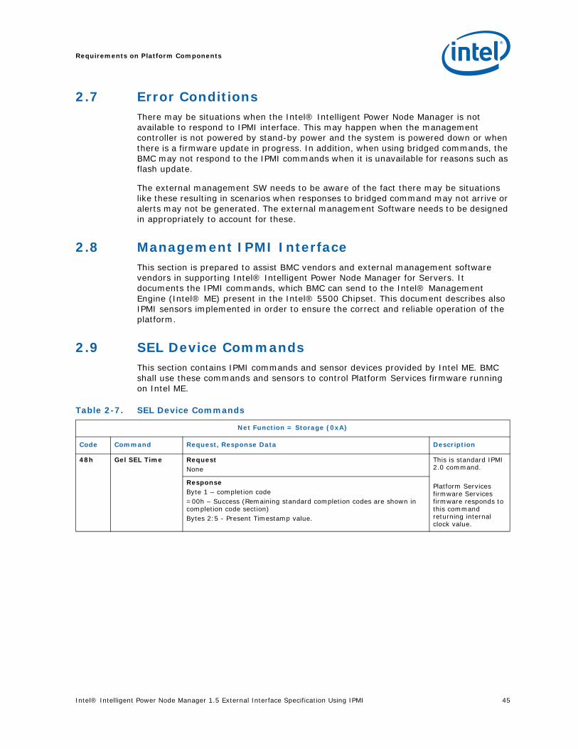
Intel® Intelligent Power Node Manager 1.5 External Interface Specification Using IPMI 45
Requirements on Platform Components
2.7 Error ConditionsThere may be situations when the Intel® Intelligent Power Node Manager is not available to respond to IPMI interface. This may happen when the management controller is not powered by stand-by power and the system is powered down or when there is a firmware update in progress. In addition, when using bridged commands, the BMC may not respond to the IPMI commands when it is unavailable for reasons such as flash update.
The external management SW needs to be aware of the fact there may be situations like these resulting in scenarios when responses to bridged command may not arrive or alerts may not be generated. The external management Software needs to be designed in appropriately to account for these.
2.8 Management IPMI InterfaceThis section is prepared to assist BMC vendors and external management software vendors in supporting Intel® Intelligent Power Node Manager for Servers. It documents the IPMI commands, which BMC can send to the Intel® Management Engine (Intel® ME) present in the Intel® 5500 Chipset. This document describes also IPMI sensors implemented in order to ensure the correct and reliable operation of the platform.
2.9 SEL Device CommandsThis section contains IPMI commands and sensor devices provided by Intel ME. BMC shall use these commands and sensors to control Platform Services firmware running on Intel ME.
Table 2-7. SEL Device Commands
Net Function = Storage (0xA)
Code Command Request, Response Data Description
48h Gel SEL Time RequestNone
This is standard IPMI 2.0 command.
Platform Services firmware Services firmware responds to this command returning internal clock value.
ResponseByte 1 – completion code=00h – Success (Remaining standard completion codes are shown in completion code section)Bytes 2:5 - Present Timestamp value.

Requirements on Platform Components
46 Intel® Intelligent Power Node Manager 1.5 External Interface Specification Using IPMI
2.10 IPMI Device “Global” Commands
Net Function = App (0x6)
Code Command Request, Response Data Description
01h Get Device ID RequestNone
This is standard IPMI 2.0 command.
ResponseByte 1 – completion code=00h – Success (Remaining standard completion codes are shown in completion code section)Byte 2 - Device ID. 00h = unspecified.Byte 3 - Device Revision[7] 0 = device does not provide Device SDRs[6:4] reserved. Return as 000b.[3:0] Device Revision, binary encoded. = 0
Byte 4 Firmware Revision 1[7] Device available:0=normal operation,1= device firmware update or self-initialization in progress. [6:0] Major Firmware Revision, binary encoded = 1
Byte 5 - Firmware Revision 2: Minor Firmware Revision. BCD encoded.
Byte 6 - IPMI Version. Holds IPMI Command Specification Version. BCD encoded.00h = reserved.Bits 7:4 hold the Least Significant digit of the revision, whileBits 3:0 hold the Most Significant digit. =02h to indicate revision 2.0.Byte 7 - Additional Device Support. Lists the IPMI ‘logical device’ commands and functions that the controller supports that are in addition to the mandatory IPM and Application commands.[7] = 0 Not a chassis Device[6] = 0 Not a Bridge[5] = 1 IPMB Event Generator[4] = 0 Not a IPMB Event Receiver[3] = 0 FRU Inventory Device[2] = 0 SEL Device[1] = 0 SDR Repository Device[0] = 1 Sensor DeviceBytes 8:10 - Manufacturer ID = 57h, 01h, 00h.Byte 11 – Product ID Minor Version = 0x00 Byte 12 – Product ID Major Version = 0x0BBytes (13:16) Auxiliary Firmware Revision InformationByte 13 – Implemented version of SPS Firmware IPMI command specification BCD encoded = 1.3 Byte 14 – SPS Firmware build number BCD encoded = A.B Byte 15 - SPS Firmware last digit of build number and patch number BCD encoded = C.PATCHByte 16 – Image flags [7:2] – reserved. Return as 000000b [1:0] – image type= 00b – recovery image= 01b – operational image 1= 10b – operational image 2= 11b - unspecified: flash error indicationNote: Full version number is: “Major Firmware Revision. Minor Firmware Revision.ABC.PATCH” where ABC is Firmware build number.
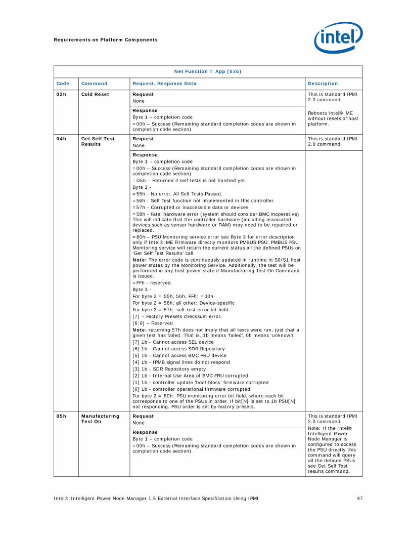
Intel® Intelligent Power Node Manager 1.5 External Interface Specification Using IPMI 47
Requirements on Platform Components
02h Cold Reset RequestNone
This is standard IPMI 2.0 command.
Reboots Intel® ME without resets of host platform.
ResponseByte 1 – completion code=00h – Success (Remaining standard completion codes are shown in completion code section)
04h Get Self Test Results
RequestNone
This is standard IPMI 2.0 command.
ResponseByte 1 – completion code=00h – Success (Remaining standard completion codes are shown in completion code section)=D5h – Returned if self tests is not finished yet. Byte 2 - =55h - No error. All Self Tests Passed.=56h - Self Test function not implemented in this controller.=57h - Corrupted or inaccessible data or devices=58h - Fatal hardware error (system should consider BMC inoperative). This will indicate that the controller hardware (including associated devices such as sensor hardware or RAM) may need to be repaired or replaced.=80h – PSU Monitoring service error see Byte 3 for error description only if Intel® ME Firmware directly monitors PMBUS PSU. PMBUS PSU Monitoring service will return the current status all the defined PSUs on ‘Get Self Test Results’ call. Note: The error code is continuously updated in runtime in S0/S1 host power states by the Monitoring Service. Additionally, the test will be performed in any host power state if Manufacturing Test On Command is issued.=FFh - reserved.Byte 3 - For byte 2 = 55h, 56h, FFh: =00hFor byte 2 = 58h, all other: Device-specificFor byte 2 = 57h: self-test error bit field.[7] – Factory Presets checksum error.[6:0] – ReservedNote: returning 57h does not imply that all tests were run, just that a given test has failed. That is, 1b means ‘failed’, 0b means ‘unknown’.[7] 1b - Cannot access SEL device[6] 1b - Cannot access SDR Repository[5] 1b - Cannot access BMC FRU device[4] 1b - IPMB signal lines do not respond[3] 1b - SDR Repository empty[2] 1b - Internal Use Area of BMC FRU corrupted[1] 1b - controller update ‘boot block’ firmware corrupted[0] 1b - controller operational firmware corruptedFor byte 2 = 80h: PSU monitoring error bit field, where each bit corresponds to one of the PSUs in order. If bit[N] is set to 1b PSU[N] not responding. PSU order is set by factory presets.
05h Manufacturing Test On
RequestNone
This is standard IPMI 2.0 command.Note: If the Intel® Intelligent Power Node Manager is configured to access the PSU directly this command will query all the defined PSUs see Get Self Test results command.
ResponseByte 1 – completion code=00h – Success (Remaining standard completion codes are shown in completion code section)
Net Function = App (0x6)
Code Command Request, Response Data Description
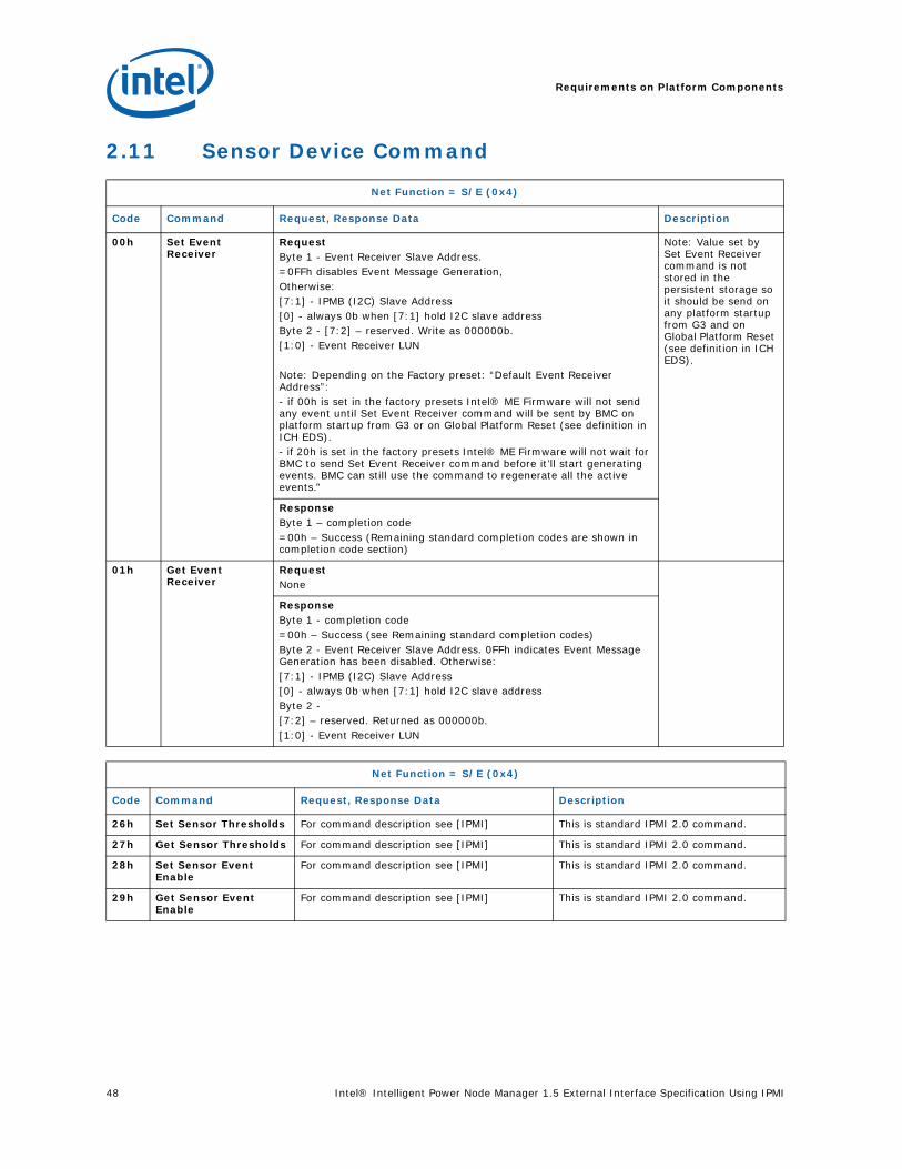
Requirements on Platform Components
48 Intel® Intelligent Power Node Manager 1.5 External Interface Specification Using IPMI
2.11 Sensor Device Command
Net Function = S/E (0x4)
Code Command Request, Response Data Description
00h Set Event Receiver
RequestByte 1 - Event Receiver Slave Address.=0FFh disables Event Message Generation,Otherwise:[7:1] - IPMB (I2C) Slave Address[0] - always 0b when [7:1] hold I2C slave addressByte 2 - [7:2] – reserved. Write as 000000b.[1:0] - Event Receiver LUN
Note: Depending on the Factory preset: “Default Event Receiver Address”:- if 00h is set in the factory presets Intel® ME Firmware will not send any event until Set Event Receiver command will be sent by BMC on platform startup from G3 or on Global Platform Reset (see definition in ICH EDS).- if 20h is set in the factory presets Intel® ME Firmware will not wait for BMC to send Set Event Receiver command before it’ll start generating events. BMC can still use the command to regenerate all the active events.”
Note: Value set by Set Event Receiver command is not stored in the persistent storage so it should be send on any platform startup from G3 and on Global Platform Reset (see definition in ICH EDS).
ResponseByte 1 – completion code=00h – Success (Remaining standard completion codes are shown in completion code section)
01h Get Event Receiver
RequestNone
ResponseByte 1 - completion code=00h – Success (see Remaining standard completion codes)Byte 2 - Event Receiver Slave Address. 0FFh indicates Event Message Generation has been disabled. Otherwise:[7:1] - IPMB (I2C) Slave Address[0] - always 0b when [7:1] hold I2C slave addressByte 2 - [7:2] – reserved. Returned as 000000b.[1:0] - Event Receiver LUN
Net Function = S/E (0x4)
Code Command Request, Response Data Description
26h Set Sensor Thresholds For command description see [IPMI] This is standard IPMI 2.0 command.
27h Get Sensor Thresholds For command description see [IPMI] This is standard IPMI 2.0 command.
28h Set Sensor Event Enable
For command description see [IPMI] This is standard IPMI 2.0 command.
29h Get Sensor Event Enable
For command description see [IPMI] This is standard IPMI 2.0 command.

Intel® Intelligent Power Node Manager 1.5 External Interface Specification Using IPMI 49
Requirements on Platform Components
2.12 IPMI OEM Device Commands
2Ah Re-arm Sensor Events For command description see [IPMI] This is standard IPMI 2.0 command.
2Bh Get Sensor Event Status
For command description see [IPMI] This is standard IPMI 2.0 command.
2Dh Get Sensor Reading For command description see [IPMI] This is standard IPMI 2.0 command.
Note: If sensor scanning is disabled for example using Factory image tool Get Sensor Reading command will return: - completion code 00h- last reading or 00h if there was not reading- and bit [6] of byte 3 set to 1.)
Net Function = SDK General Application (0x30)
Code Command Request, Response Data Description
DAh Set Cooling Coefficient
RequestByte 1 – TTL[7:4] – reserved. Write as 0000b.[3:0] – time to live in 100 ms unit – 0 indicates 100ms, 1 indicates 200 ms etc.
Byte 2 – MC address (set #1)[7:4] – reserved. Write as 0b.[3] – CPU# 0-1[2:0] – MC# 0-7 (NHM supports 0-2)
Byte 3:6 Cooling coefficient
Byte 7 – MC address (set #2 - optional)[7:4] – reserved. Write as 0b.[3] – CPU# 0-1[2:0] – MC# 0-7 (NHM supports 0-2)
Byte 8:11 Cooling coefficient Byte 12 – MC address (set #3 - optional)[7:4] – reserved. Write as 0b.[3] – CPU# 0-1[2:0] – MC# 0-7 (NHM supports 0-2)
Byte 13:16 Cooling coefficient Byte 17 – MC address (set #4 - optional)[7:4] – reserved. Write as 0b.[3] – CPU# 0-1[2:0] – MC# 0-7 (NHM supports 0-2)
Byte 18:21 Cooling coefficient
ResponseByte 1 – completion code=00h – Success (Remaining standard completion codes are shown in completion code section)=81h – MCH# out of range=82h – CPU# out of range
Net Function = S/E (0x4)
Code Command Request, Response Data Description

Requirements on Platform Components
50 Intel® Intelligent Power Node Manager 1.5 External Interface Specification Using IPMI
DCh Set ME Power State
RequestByte 1 – New power state0x00 = Turn off Intel ME powerNote: After turning-off Intel ME will wake-up on one of the following events:• Automatically when Host CPU goes to S0• Host Notify message send on the HOST SMBUS link with the Host Notify Message as specified below. In that case only Intel ME wakes-upIntel ME wake-up SMBUS host notify message definition:- SMBUS Host Address = 0001000b- Device Address = as defined using Factory preset tool (default 0x20)- Data Byte Low as defined using Factory preset tool default 0xFF- Data Byte High as defined using Factory preset tool default 0xFF
Defaults Intel ME wake-up Host Notify Message bytes Low and High can be changed using Factory preset tool.
ResponseByte 1 – completion code=00h – Success (Remaining standard completion codes are shown in completion code section)Note: The Intel ME may be turned on and off by the BMC in Sx Host CPU states. In S0/S1 Host CPU state command will return D5h error code
Net Function = SDK General Application (0x30)
Code Command Request, Response Data Description

Intel® Intelligent Power Node Manager 1.5 External Interface Specification Using IPMI 51
Requirements on Platform Components
DDh Send Raw PECI RequestByte 1 – Flags[7]- 1b=Disable message formal checking. If the bit is set, SPS firmware does not check the PECI request format included in the message. If the bit is cleared, SPS firmware checks the below fields:• PECI command code – the only allowed commands are Ping, GetDIB, GetTemp, PCIConfigRd, PCIConfigWr, MbxSend, MbxGet• Target Address – this is checked only for MbxSend and MbxGet commands and must be in the range 0x30 – 0x33• Domain ID – must be either Domain 0 or Domain 1. For MbxSend and MbxGet commands it must be Domain 0. The value is not checked for GetDIB and Ping commands because they are not multi-domain commands.• Read Length – must fit the limits for the PECI command• Write Length – must fit the limits for the PECI command• AWFSC – it is checked only if “Update AW FCS byte in message data” is set to zero[5:6]- reserved. Write as 00b.[4]- 1b=Automatically handle mailbox command2. If the bit is set, SPS firmware automatically sends MbxGet PECI command after successful MbxSet PECI command. This is done to ensure that 1 ms mailbox timeout is met. The results of the MbxGet PECI command can be retrieved by sending Send Raw PECI IPMI command with MbxGet PECI command embedded. If “Automatically handle mailbox” bit is set in IPMI request containing MbxSend or MbxGet PECI commands, SPS FW checks the PECI command format regardless of “Disable message formal checking” flag value. If MbxSend PECI command is sent with “Automatically handle mailbox” bit set, the corresponding MbxGet PECI command must also have the bit set. Otherwise the result of the MbxGet command is undefined.The bit must be set to 0 for all PECI commands different than Send Mailbox or Get Mailbox.[3]- 1b=Do not report FCS errors in completion code. If the bit is set, SPS firmware does not returns “bad Write FCS” or “Bad Read FCS” completion codes. In this case, BMC can learn that the transaction failed by checking Write FCS and Read FCS fields in the IPMI response message. The flag does not disable PECI command retries.[2]- 1b=Disable automatic command retry. If the bit is set, SPS firmware does not retry the PECI command automatically. If the bit is cleared, SPS firmware retries automatically when the PECI transaction failed due to Write FCS or Read FCS error.[1]- 1b=Use SST instead of PECI interface. If the bit is set, SPS firmware redirects the request to SST instead of PECI bus.[0]- 1b=Update AW FCS byte in message data1) . If the bit is set, SPS firmware does not use AWFCS field supplied in the IPMI command, but calculates the correct AWFCS by itself. Byte 2 – Target AddressByte 3 – Write LengthByte 4 – Read LengthByte 5:M – PECI command and PECI command write data2
1) This option shall be used only for commands supporting AW FCS. Request shall contain placeholder for AW FCS byte, this byte must be also included in Write Length.2) This field does not exist for PECI Ping command
The command initiates PECI transaction on PECI bus.
Note: In order to use this command OEM needs to sign “INTEL LICENSE AGREEMENT TO PLATFORM ENVIRONMENT CONTROL INTERFACE SPECIFICATION”.This command is not supported when Platform Instrumentation Enabled is set to ‘false’ using Flash Image Tool.
Net Function = SDK General Application (0x30)
Code Command Request, Response Data Description
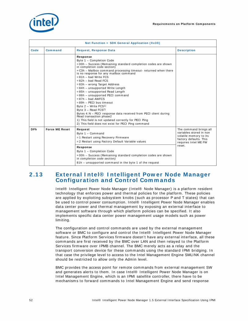
Requirements on Platform Components
52 Intel® Intelligent Power Node Manager 1.5 External Interface Specification Using IPMI
2.13 External Intel® Intelligent Power Node Manager Configuration and Control CommandsIntel® Intelligent Power Node Manager (Intel® Node Manager) is a platform resident technology that enforces power and thermal policies for the platform. These policies are applied by exploiting subsystem knobs (such as processor P and T states) that can be used to control power consumption. Intel® Intelligent Power Node Manager enables data center power and thermal management by exposing an external interface to management software through which platform policies can be specified. It also implements specific data center power management usage models such as power limiting.
The configuration and control commands are used by the external management software or BMC to configure and control the Intel® Intelligent Power Node Manager feature. Since Platform Services firmware doesn’t have any external interface, all these commands are first received by the BMC over LAN and then relayed to the Platform Services firmware over IPMB channel. The BMC merely acts as a relay and the transport conversion device for these commands using the standard IPMI bridging. In that case the privilege level to access to the Intel Management Engine SMLINK channel should be restricted to allow only the Admin level.
BMC provides the access point for remote commands from external management SW and generates alerts to them. In case Intel® Intelligent Power Node Manager is on Intel Management Engine, which is an IPMI satellite controller, there have to be mechanisms to forward commands to Intel Management Engine and send response
ResponseByte 1 – Completion Code=00h – Success (Remaining standard completion codes are shown in completion code section)=C3h – Mailbox command processing timeout- returned when there is no response for any mailbox command=81h – bad Write FCS=82h – bad Read FCS=83h – wrong Target Address=84h – unsupported Write Length=85h – unsupported Read Length=86h – unsupported PECI command=87h – bad AWFCS=89h – PECI bus timeoutByte 2 – Write FCS1)
Byte 3 – Read FCS2)
Bytes 4:N – PECI response data received from PECI client during Read transaction phase21) This field is not updated correctly for PECI Ping2) This field does not exist for PECI Ping command
DFh Force ME Reset RequestByte 1 – Command=1 Restart using Recovery Firmware=2 Restart using Factory Default Variable values
The command brings all variables stored in non volatile memory to its factory defaults. This requires Intel ME FW reset.Response
Byte 1 – Completion Code=00h – Success (Remaining standard completion codes are shown in completion code section)81h – unsupported command in the byte 1 of the request
Net Function = SDK General Application (0x30)
Code Command Request, Response Data Description
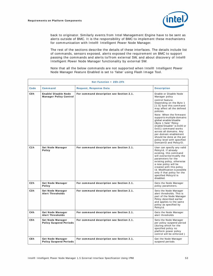
Intel® Intelligent Power Node Manager 1.5 External Interface Specification Using IPMI 53
Requirements on Platform Components
back to originator. Similarly events from Intel Management Engine have to be sent as alerts outside of BMC. It is the responsibility of BMC to implement these mechanisms for communication with Intel® Intelligent Power Node Manager.
The rest of the sections describe the details of these interfaces. The details include list of commands, sensors exposed, alerts exposed the requirement on BMC to support passing the commands and alerts to/from external SW, and about discovery of Intel® Intelligent Power Node Manager functionality by external SW.
Note that all the below commands are not supported when Intel® Intelligent Power Node Manager Feature Enabled is set to ‘false’ using Flash Image Tool.
Net Function = 2Eh-2Fh
Code Command Request, Response Data Description
C0h Enable/Disable Node Manager Policy Control
For command description see Section 2.1. Enable or Disable Node Manager policy control feature. Depending on the Byte 1 [1:0] byte this command may affect all the defined policies.Note: When the firmware supports multiple domains global enable/disable (Byte 1 field “Policy enable/Disable” is 0x00 or 0x01) command works across all domains. Any per-domain enablement should be done at the per policy level with specified DomainID and PolicyID.
C1h Set Node Manager Policy
For command description see Section 2.1. User can specify any valid PolicyId. If already existing, this command will overwrite/modify the parameters for the existing policy, otherwise a new policy will be created with this policy Id. Modification is possible only if that policy for the specified PolicyId is disabled.
C2h Get Node Manager Policy
For command description see Section 2.1. Gets the Node Manager policy parameters.
C3h Set Node Manager Alert Thresholds
For command description see Section 2.1. Sets the Node Manager alert thresholds. This is part of the Node Manager Policy described earlier and applies to the same policy as specified by PolicyId.
C4h Get Node Manager Alert Thresholds
For command description see Section 2.1. Gets the Node Manager alert thresholds
C5h Set Node Manager Policy Suspend Periods
For command description see Section 2.1. Sets the Node Manager per policy suspend period (during which for the specified policy no platform power policy control will be enforced )
C6h Get Node Manager Policy Suspend Periods
For command description see Section 2.1. Get the Node Manager suspend periods

Requirements on Platform Components
54 Intel® Intelligent Power Node Manager 1.5 External Interface Specification Using IPMI
C7h Reset Node Manager Statistics
For command description see Section 2.1. Resets the Node Manager Power Statistics
C8h Get Node Manager Statistics
For command description see Section 2.1. Get the Node Manager Power StatisticsNote that the average values provided here may be different from the averaged values used by Node Manager for taking corrective action or triggering alerts based a ‘Set Node Manager Alert Threshold’ because the averaging period for the two could be different.Implementation Note: For the per Policy statistics the actual reported minimum and maximum values may include reading values up to 1 minute older than the defined Statistics Reporting Period (if Statistics Reporting Period is above 60 seconds)Minimum, maximum, and current values returned by the command are averaged over 1 second (inside PSU and/or internally).
C9h Get Node Manager Capabilities
For command description see Section 2.1. Get Node Manager capabilities
CAh Get Node Manager Version
For command description see Section 2.1. Get Node Manager firmware version.
CBh Set Node Manager Power Draw Range
For command description see Section 2.1. Set the Min/Max power consumption ranges.On Intel® Xeon® 5500 Platform if set to 0 the min/max power draw values will be taken from the BIOS first. See [ME-BIOS].Only if min/max values are not provided by the BIOS no validation of policy parameters against minimum power consumption will be performed if the min/max values are set to 0.
CEh Set Node Manager Alert Destination
For command description see Section 2.1. Provide alert destination information for Intel® Intelligent Power Node Manager to send alerts for “threshold exceeded” and “Node Manager Health” events.
CFh Get Node Manager Alert Destination
For command description see Section 2.1. Provides alert destination information that is used to send alerts from for Node Manager.
Net Function = 2Eh-2Fh
Code Command Request, Response Data Description
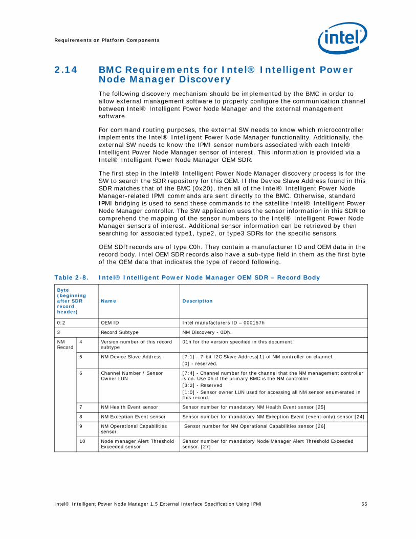
Intel® Intelligent Power Node Manager 1.5 External Interface Specification Using IPMI 55
Requirements on Platform Components
2.14 BMC Requirements for Intel® Intelligent Power Node Manager DiscoveryThe following discovery mechanism should be implemented by the BMC in order to allow external management software to properly configure the communication channel between Intel® Intelligent Power Node Manager and the external management software.
For command routing purposes, the external SW needs to know which microcontroller implements the Intel® Intelligent Power Node Manager functionality. Additionally, the external SW needs to know the IPMI sensor numbers associated with each Intel® Intelligent Power Node Manager sensor of interest. This information is provided via a Intel® Intelligent Power Node Manager OEM SDR.
The first step in the Intel® Intelligent Power Node Manager discovery process is for the SW to search the SDR repository for this OEM. If the Device Slave Address found in this SDR matches that of the BMC (0x20), then all of the Intel® Intelligent Power Node Manager-related IPMI commands are sent directly to the BMC. Otherwise, standard IPMI bridging is used to send these commands to the satellite Intel® Intelligent Power Node Manager controller. The SW application uses the sensor information in this SDR to comprehend the mapping of the sensor numbers to the Intel® Intelligent Power Node Manager sensors of interest. Additional sensor information can be retrieved by then searching for associated type1, type2, or type3 SDRs for the specific sensors.
OEM SDR records are of type C0h. They contain a manufacturer ID and OEM data in the record body. Intel OEM SDR records also have a sub-type field in them as the first byte of the OEM data that indicates the type of record following.
Table 2-8. Intel® Intelligent Power Node Manager OEM SDR – Record Body
Byte (beginning after SDR record header)
Name Description
0:2 OEM ID Intel manufacturers ID – 000157h
3 Record Subtype NM Discovery - 0Dh.
NM Record
4 Version number of this record subtype
01h for the version specified in this document.
5 NM Device Slave Address [7:1] - 7-bit I2C Slave Address[1] of NM controller on channel.[0] - reserved.
6 Channel Number / Sensor Owner LUN
[7:4] - Channel number for the channel that the NM management controller is on. Use 0h if the primary BMC is the NM controller[3:2] - Reserved[1:0] - Sensor owner LUN used for accessing all NM sensor enumerated in this record.
7 NM Health Event sensor Sensor number for mandatory NM Health Event sensor [25]
8 NM Exception Event sensor Sensor number for mandatory NM Exception Event (event-only) sensor [24]
9 NM Operational Capabilities sensor
Sensor number for NM Operational Capabilities sensor [26]
10 Node manager Alert Threshold Exceeded sensor
Sensor number for mandatory Node Manager Alert Threshold Exceeded sensor. [27]
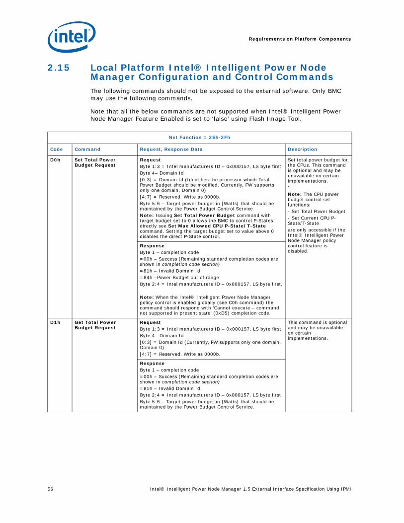
Requirements on Platform Components
56 Intel® Intelligent Power Node Manager 1.5 External Interface Specification Using IPMI
2.15 Local Platform Intel® Intelligent Power Node Manager Configuration and Control CommandsThe following commands should not be exposed to the external software. Only BMC may use the following commands.
Note that all the below commands are not supported when Intel® Intelligent Power Node Manager Feature Enabled is set to ‘false’ using Flash Image Tool.
Net Function = 2Eh-2Fh
Code Command Request, Response Data Description
D0h Set Total Power Budget Request
RequestByte 1:3 = Intel manufacturers ID – 0x000157, LS byte firstByte 4– Domain Id[0:3] = Domain Id (Identifies the processor which Total Power Budget should be modified. Currently, FW supports only one domain, Domain 0)[4:7] = Reserved. Write as 0000b.Byte 5:6 – Target power budget in [Watts] that should be maintained by the Power Budget Control Service Note: Issuing Set Total Power Budget command with target budget set to 0 allows the BMC to control P-States directly see Set Max Allowed CPU P-State/T-State command. Setting the target budget set to value above 0 disables the direct P-State control.
Set total power budget for the CPUs. This command is optional and may be unavailable on certain implementations.’Note: The CPU power budget control set functions:- Set Total Power Budget- Set Current CPU P-State/T-Stateare only accessible if the Intel® Intelligent Power Node Manager policy control feature is disabled.
ResponseByte 1 – completion code=00h – Success (Remaining standard completion codes are shown in completion code section)=81h – Invalid Domain Id=84h –Power Budget out of rangeByte 2:4 = Intel manufacturers ID – 0x000157, LS byte first.
Note: When the Intel® Intelligent Power Node Manager policy control is enabled globally (see C0h command) the command should respond with ‘Cannot execute – command not supported in present state’ (0xD5) completion code.
D1h Get Total Power Budget Request
RequestByte 1:3 = Intel manufacturers ID – 0x000157, LS byte firstByte 4– Domain Id[0:3] = Domain Id (Currently, FW supports only one domain, Domain 0)[4:7] = Reserved. Write as 0000b.
This command is optional and may be unavailable on certain implementations.
ResponseByte 1 – completion code=00h – Success (Remaining standard completion codes are shown in completion code section)=81h – Invalid Domain IdByte 2:4 = Intel manufacturers ID – 0x000157, LS byte first Byte 5:6 – Target power budget in [Watts] that should be maintained by the Power Budget Control Service.
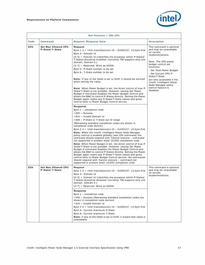
Intel® Intelligent Power Node Manager 1.5 External Interface Specification Using IPMI 57
Requirements on Platform Components
D2h Set Max Allowed CPU P-State/T-State
RequestByte 1:3 = Intel manufacturers ID – 0x000157, LS byte firstByte 4– Domain Id[0:3] = Domain Id (Identifies the processor which P-States/T-States should be modified. Currently, FW supports only one domain, Domain 0.)[4:7] = Reserved. Write as 0000b.Byte 5– P-State number to be setByte 6– T-State number to be set
Note: If any of the fields is set to 0xFF, it should be omitted when setting the value.
Note: When Power Budget is set, the direct control of max P-State/T-State is not possible. However, issuing Set Power Budget 0 command disables the Power Budget Control and allows the BMC to control P-States directly. Setting the Power Budget again resets any P-State/T-State values and gives control back to Power Budget Control service.
This command is optional and may be unavailable on certain implementations.
Note: The CPU power budget control set functions:- Set Total Power Budget- Set Current CPU P-State/T-Stateare only accessible if the Intel® Intelligent Power Node Manager policy control feature is disabled.
ResponseByte 1 – completion code=00h – Success=81h – Invalid Domain Id=8Ah – P-State or T-State out of range(Remaining standard completion codes are shown in completion code section)Byte 2:4 = Intel manufacturers ID – 0x000157, LS byte first Note: When the Intel® Intelligent Power Node Manager policy control is enabled globally (see C0h command) the command should respond with ‘Cannot execute – command not supported in present state’ (0xD5) completion code.Note: When Power Budget is set, the direct control of max P-State/T-State is not possible. However, issuing Set Power Budget 0 command disables the Power Budget Control and allows the BMC to control P-States directly. Setting the Power Budget again resets any P-State/T-State values and gives control back to Power Budget Control service, the commands should respond with ‘Cannot execute – command not supported in present state’ (0xD5) completion code.
D3h Get Max Allowed CPU P-State/T-State
RequestByte 1:3 = Intel manufacturers ID – 0x000157, LS byte firstByte 4– Domain Id[0:3] = Domain Id (Identifies the processor which P-States/T-States should be obtained. Currently, FW supports only one domain, Domain 0.)[4:7] = Reserved. Write as 0000b.
This command is optional and may be unavailable on certain implementations.
ResponseByte 1 – completion code=00h – Success (Remaining standard completion codes are shown in completion code section)=81h – Invalid Domain IdByte 2:4 = Intel manufacturers ID – 0x000157, LS byte first Byte 5– Current maximum P-StateByte 6– Current maximum T-StateNote: If any of the fields is set to 0xFF, it means that value is unavailable.
Net Function = 2Eh-2Fh
Code Command Request, Response Data Description

Requirements on Platform Components
58 Intel® Intelligent Power Node Manager 1.5 External Interface Specification Using IPMI
D4h Get Number Of P-States/T-StatesRequest
RequestByte 1:3 = Intel manufacturers ID – 0x000157, LS byte firstByte 4– Domain Id[0:3] = Domain Id (Identifies the processor which P-States/T-States should be obtained. Currently, FW supports only one domain, Domain 0.)[4:7] = Reserved. Write as 0000b.
This command is optional and may be unavailable on certain implementations.
ResponseByte 1 – completion code=00h – Success (Remaining standard completion codes are shown in completion code section)=81h – Invalid Domain IdByte 2:4 = Intel manufacturers ID – 0x000157, LS byte first Byte 5 – Number of P-States available on the platform. This number will be always be 1 or more, even if BIOS will pass information that 0 P-states are supported.Byte 6 – Current Number of T-States available on the platform. This number will be always be 1 or more, even if BIOS will pass information that T-states are supported.
Net Function = 2Eh-2Fh
Code Command Request, Response Data Description

Intel® Intelligent Power Node Manager 1.5 External Interface Specification Using IPMI 59
Requirements on Platform Components
D6h Set Host CPU data RequestByte 1:3 = Intel manufacturers ID – 0x000157, LS byte firstByte 4 – Domain Id[0:3] = Domain Id (Identifies the set of processors supported by the domain. Currently, FW supports only one domain, Domain 0.)[4:7] = Reserved. Write as 0000b.Byte 5 – Host CPU data. [7] – set to 1 for End of POST notification[6:5] – reserved. Write as 00b [4] – set to 1 if Host CPU discovery data is provided with that command. This information should be passed to Node Manager on each platform boot. [3:0] – reserved. Write as 000b.
Note: The Bytes 25:6 are ignored if Byte 5 bit [4] is set to 0.If Byte 5 bit [4] is set to 1 Bytes 24:6 should describe the actual Host CPU data of the platform. Additionally, Bytes 24:6 should be set to 0 if the CPU discovery data is passed to NM directly by the BIOS.Per processor discovery data will be provided only for the lowest number processor that is installed. In the multiprocessor environment all other processors installed on board should match the number of performance states and each processor performance state must have identical performance and power-consumption parametersByte 6 – Number of P-States supported by the current platform CPU configuration:= 0 – if P-states are disabled by the user.= 1 – if CPU does not support more P-states or the in the multiprocessor environment some processors installed on board don’t match the lowest number processor power-consumption parameters.= 2..255 – actual number of supported P-States by the lowest number processor. Note: other processors should match the number of performance states of lowest number processor. Byte 7 – Number of T-States supported by the current platform CPU configuration= 0 – if T-states are disabled by the user.= 1..255 – actual number of supported T-States by the lowest number processor. Note: other processors should match the number of throttling states of lowest number processor.Byte 8 – Number of installed CPUs/socket. This value is calculated as a number of all CPUs/sockets present on the board during platform boot.Bytes 9:16 - Processor Discovery Data for the lowest number processor in Lisped-first order. Turbo power current Limit MSR 1ACh for the lowest number processor passed by BIOS. Bytes 17:24 - Processor Discovery Data 2 for the lowest number processor in Lisped-first order. Platform Info MSR 0CEh for the lowest number processor passed by BIOS. Byte 25 - ICC_TDC reading from PECI for the lowest number processor. In a multiprocessor environment all the processors should have common ICC_TDC. Set to 0 if ICC_TDC of processors don’t match and set the number of allowed P-States to 0 as well. Set to 0 if the PECI is attached to ICH9 or if the SPS Firmware should query ICC_TDC using ‘OEM Get Reading’ with type “ICC_TDC reading from PECI”
This command is optional and may be unavailable on certain implementations.
Note: This command is obligatory if Node Manager is a part the SPS Firmware and if BIOS does not implement HECI-1 communication to Intel ME. This information should be passed to Intel® Intelligent Power Node Manager on each platform boot and on each CPU insert/removal.
Net Function = 2Eh-2Fh
Code Command Request, Response Data Description

Requirements on Platform Components
60 Intel® Intelligent Power Node Manager 1.5 External Interface Specification Using IPMI
ResponseByte 1 – completion code=00h – Success (Remaining standard completion codes are shown in completion code section)=81h – Invalid Domain Id=8Ah – P-State or T-State out of rangeByte 2:4 = Intel manufacturers ID – 0x000157, LS byte first
D7h Set PSU ConfigurationRequest
RequestByte 1:3 = Intel manufacturers ID – 0x000157, LS byte firstByte 4 – Domain Id[0:3] = Domain Id (Identifies Domain which uses the defined PSU set). Currently, FW supports only one domain, Domain 0.)[4:7] = Reserved. Write as 0000b.Byte 5 – PMBUS PSU address 1. Node Manager will monitor the presence of the defined PSU.[0] – PSU mode:=1 – the PSU is installed and lack of power readings should be reported to Management Console=0 (default) – the PSU is installed or may be attached in the future. [1:7] – 7 bit PSU SMBUS address. Set to 00h if address is not used.Bytes 6:12 – PMBUS PSU address 2 to PMBUS PSU 8. Encoding as in the Byte 5.
This command may override the supported set of PSUs by defining a set of all supported PSUs. Only the PSU SMBUS addresses are stored in the persistent storage.This command should be send to Intel® Intelligent Power Node Manager by BMC if the lack of reading from the defined PSU should be reported to the Management Console using Intel® Intelligent Power Node Manager Health Event. Otherwise, Intel® Intelligent Power Node Manager will send a notification only if all PSUs will disappear and the will be no power readings available.
ResponseByte 1 – completion code=00h – Success(Remaining standard completion codes are shown in completion code section)=81h – Invalid Domain IdByte 2:4 = Intel manufacturers ID – 0x000157, LS byte first
Net Function = 2Eh-2Fh
Code Command Request, Response Data Description

Intel® Intelligent Power Node Manager 1.5 External Interface Specification Using IPMI 61
Requirements on Platform Components
2.16 Intel Management Engine Firmware Update IPMI CommandsDepending on the SPI flash availability the image and the usage model Server Platform Services Firmware supports the following options:
• Single operational image with the recovery image. In that case the command set for image upgrade is available only from the recovery image. In order to upgrade an operational image a boot to recovery image must be performed. Command “Get Device Id” can be used to query if recovery image is loaded. Recovery image supports only FW upgrade commands. To exit the recovery image and finish the operational image upgrade “Cold reset” command should be sent to in order to boot the new operational image.
• Dual operation image with the recovery image. In that case the command set for image upgrade is available from any operational image and from recovery image as well. During upgrade all enabled functionalists will work. However, the response to IPMI commands may be slower.
Operational image upgrades only the code. Persistent settings, factory presets and recovery firmware remain unchanged after the operational code upgrade.
Runtime data sent by BIOS and/or BMC is preserved between cold resets of Intel Management Engine .
D8h Get PSU Configuration RequestByte 2:4 = Intel manufacturers ID – 0x000157, LS byte firstByte 4– Domain Id[0:3] = Domain Id (Identifies Domain which uses the defined PSU set). Currently, FW supports only one domain, Domain 0.)[4:7] = Reserved. Write as 0000b.’
ResponseByte 1 – completion code=00h – Success(Remaining standard completion codes are shown in completion code section)=81h – Invalid Domain Id Byte 2:4 = Intel manufacturers ID – 0x000157, LS byte firstByte 5 – Domain Id[0:3] = Domain Id (Identifies Domain which uses the defined PSU set). Currently, FW supports only one domain, Domain 0.)[4:7] = Reserved. Return as 0000b.Byte 6 – PMBUS PSU address 1. Node Manager will monitor the presence of the defined PSU.[7:1] – 7 bit PSU SMBUS address. Set to 00h if address is not used.[0] – PSU mode:=1 – the PSU is installed and lack of power readings should be reported to Management Console=0 (default) – the PSU is installed or may be attached in the future. Bytes 7:13 – PMBUS PSU address 2 to PMBUS PSU 8. Encoding as in the Byte 6.
Net Function = 2Eh-2Fh
Code Command Request, Response Data Description

Requirements on Platform Components
62 Intel® Intelligent Power Node Manager 1.5 External Interface Specification Using IPMI
All the below Firmware Update commands are not available 5 seconds after platform or CPU reset. In such case, SPS firmware returns D5h (Command Not Supported In Present Starts) completion code.
Net Function = SDK General Application (0x30)
Code Command Request, Response Data Description
A0h Online Update Prepare For Update
RequestNone
This is the first command that should be sent to initiate FW upgrade.This command restarts the FW upgrade to the initial state.Upon success command Online Update Get Status returns “update requested” status. Upon failure “update unit failed” is returned.
ResponseByte 1 – completion code=00h – Success (Remaining standard completion codes are shown in section 2.11.3)=80h – Operation refused (too many requests)=81h – Flash error=82h – Operation in progress (flash erase)
A1h Online Update Open Area
RequestByte 1 – Area type=00h – Reserved=01h – Operational code=02h – PIA=03h – SDRByte 2 – Area flags[0:7] – Reserved. Write as 00000000b.
On Intel® Xeon® 5500 Platform only update of operational code will be supportedNote: Online Update Open Area invalidates the rollback image partition. Only a successful image upload allows to switch to a rollback image.Upon success command Online Update Get Status returns “update failed” status in case of flash error or “update in progress” status in case of success.This command performs access to the flash so the response will be sent after completing the operation and may take longer than 250ms.
ResponseByte 1 – completion code=00h – Success (Remaining standard completion codes are shown in completion code section)80h – Operation refused. After this error code the FW upgrade should be reinitialized by sending Online Update Prepare For Update command. 81h – Flash error. After this error code the FW upgrade should be reinitialized by sending Online Update Prepare For Update command
A2h Online Update Write Area
RequestByte 1 – Sequence number - Must start with 0 valueByte 2:N – Area data, where <N> should not exceed 25.
This command writes data into opened area.Upon success command Online Update Get Status returns “update failed” status in case of flash error or “update in progress” status otherwise. This command performs access to the flash so the response will be sent after completing the operation and may take longer than 250ms.
ResponseByte 1 – completion code=00h – Success=80h – Operation refused. After this error code the FW upgrade should be reinitialized by sending Online Update Prepare For Update command.=81h – Flash error. After this error code the FW upgrade should be reinitialized by sending Online Update Prepare For Update command.

Intel® Intelligent Power Node Manager 1.5 External Interface Specification Using IPMI 63
Requirements on Platform Components
A3h Online Update Close Area
RequestBytes 1:4 – Area size in bytesBytes 5:6 – Area checksum. Byte 6 should be set to 0. Byte 5 is a CRC8 ATM HEC (based on x8 + x2 + x + 1 polynomial) calculated over the operational binary image directly from the distribution package i.e SPSOperational.bin file.
This command verifies the image checksum and size.Upon success command Online Update Get Status returns “update failed” status in case of checksum verification failure or “update requested” status otherwise.Note: Recovery image registers newly updated image automatically after Write Area command, so there is no need to send Register Update and Close Area commands when the firmware update procedure is done in Intel ME recovery mode.
ResponseByte 1 – completion code=00h – Success (Remaining standard completion codes are shown in completion code section)=80h – Operation refused. Wrong CRC or image length mismatch. After this error code the FW upgrade should be reinitialized by sending Online Update Prepare For Update command.=81h – Flash Error. After this error code the FW upgrade should be reinitialized by sending Online Update Prepare For Update command.=82h – In Progress. Not used on Intel® Xeon® 5500 Platform.
A4h Online Update Register Update
RequestByte 1 – update type=0 – Reserved=1 – Normal update. Use the new image for the next boot. Use this update type to verify and to switch to a newly uploaded image – after a successful Online Update Close Area command. Upon success command Online Update Get Status returns “update failed” status in case of image verification error or “update success” status otherwise.=2 – Reserved=3 – Manual rollback. Use this update type to cancel the switch to a new image and to use the current code – when executed right after Online Update Prepare For Update command. Upon success command Online Update Get Status returns “update failed” status in case of image verification error or “update rolled back” status otherwise. =4 – Abort update. Exits upgrade. Upon success command Online Update Get Status returns “Update Aborted” status. Byte 2 – dependent flags[0:7] – Reserved. Write as 00000000b.
Instructs the controller that all areas to be updated have been sent and schedules an update to occur on the next system reset or system power cycle. Upon success command Online Update Get Status returns status as described on the Figure below.Note: Recovery image registers newly updated image automatically after Write Area command, so there is no need to send Register Update and Close Area commands when the firmware update procedure is done in Intel ME recovery mode..
ResponseByte 1 – completion code=00h – Success (Remaining standard completion codes are shown in completion code section)=80h – Operation refused. =CDh – invalid field
Net Function = SDK General Application (0x30)
Code Command Request, Response Data Description
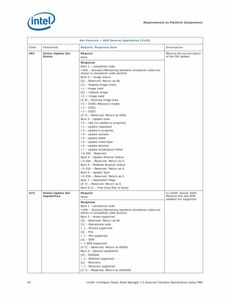
Requirements on Platform Components
64 Intel® Intelligent Power Node Manager 1.5 External Interface Specification Using IPMI
A6h Online Update Get Status
RequestNone
Returns the current status of the FW Update
ResponseByte 1 – completion code=00h – Success (Remaining standard completion codes are shown in completion code section)Byte 2 – Image status [0] – Reserved. Return as 0b.[1] – Staging image (new)=1 - Image valid[2] – rollback image=1 = Image valid[3:4] – Running image area=0 – CODE (Recovery mode)=1 – COD1=2 – COD2[5:7] – Reserved. Return as 000b.Byte 3 – Update state =0 – Idle (no update in progress)=1 – update requested=2 – update in progress =3 – update success=4 – update failed=5 – update rolled back=6 – update aborted=7 – update initialization failed=8-255 - Reserved Byte 4 – Update Attempt Status=0-255 – Reserved. Return as 0.Byte 5 – Rollback Attempt Status=0-255 – Reserved. Return as 0. Byte 6 – Update Type=0-255 – Reserved. Return as 0. Byte 7 – Dependent Flags[0:7] – Reserved. Return as 0. Byte 8:11 – Free Area Size in bytes
A7h Online Update Get Capabilities
RequestNone
In Intel® Xeon® 5500 Platform PIA and SDR updates not supported
ResponseByte 1 – completion code=00h – Success (Remaining standard completion codes are shown in completion code section)Byte 2 – Areas supported [0] – Reserved. Return as 0b.[1] – Operational code= 1 - Pocked supported [2] – PIA= 1 - PIA supported [3] – SDR= 1 SDR supported[4:7] – Reserved. Return as 0000b.Byte 3 – Special capabilities[0] – Rollback= 1 - Rollback supported[1] – Recovery= 1 - Recovery supported[2:7] – Reserved. Return as 000000b.
Net Function = SDK General Application (0x30)
Code Command Request, Response Data Description
Intel® Intelligent Power Node Manager 1.5 External Interface Specification Using IPMI 65
Requirements on Platform Components
2.17 Online Update FlowThe sequence of events that occurs during a full update with rollback is as follows (Figure 2-2)3
Note: **3(In a case of single operational image a boot to recovery image should be made first by issuing Force ME)
1. This step is optional for the dual operational image. Switch to recovery mode by sending Force ME Reset command or by asserting Recovery jumper during platform startup from G3.
2. The online update application sends an Online Update Prepare for Update command, causing the Intel® ME to re-initialize the staging image and enter the update requested state. Update state returned by Online Update Get Status command should return value 1 – update requested or 7 – update unit failed in a case of flash error.
3. The online update application sends an Online Update Open Area command, telling the Intel® ME to create an area in the staging image and prepare to receive download data of the specified type. Update state returned by Online Update Get Status should return value 2 – update in progress unless problem occurs with the area preparation. In that case update will return value 4 – update failed.
4. The online update application sends multiple Online Update Write Area commands to fill the area and then sends an Online Update Close Area command to indicate the area is finished. The Online Update Close Area command contains length and checksum information that allows the Intel® ME to validate that all data was successfully received. Update state returned by Online Update Get Status should return value 2 – update in progress in a case of flash write success until Online Update Close Area command will be send. From that time update state should return value 1 – update requested or 4 – update failed depending on the CRC verification.
5. The online update application repeats the Online Update Open Area, Online Update Write Area, and Online Update Close Area sequence until all areas that are to be updated have been downloaded. Update state returned by Online Update Get Status should return value 2 – update in progress in a case of flash write success until Online Update Close Area command will be sent. From that time update state should return value 1 – update requested or 4 – update failed depending on the checksum verification for details see Online Update Close Area command description.
6. The online update application sends an Online Update Register4 Update command to indicate the download is complete and is ready to be enacted. The Intel® ME verifies the validity of the staging area image and set the status accordingly. The Intel® ME enters the pending state. Update state returned by Online Update Get Status should return value 3 – update success (in a case of successful verification) or 4 – update failed (in a case of verification failure) unless Online Update Register Update command was sent without finalizing update with Online Update Close Area command. In that case update state will return value 6 – update aborted. Value 5 – update roll back will be returned after successful manual rollback.
Note: **4(Command not required if update is performed from Recovery image. Recovery image registers newly updated image automatically after Close Area command.)
7. A system reset occurs (potentially much later). This step is especially required for exiting from the recovery mode.
8. The Intel Management Engine hard resets itself to allow the boot code to run.
9. The boot code verifies the status of the new downloaded operational image, and transfers control to and executes the new image if verification succeeds.
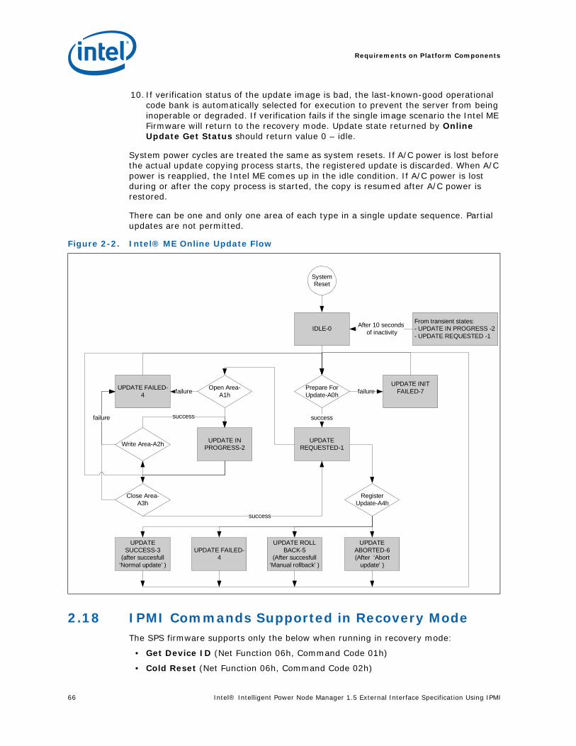
Requirements on Platform Components
66 Intel® Intelligent Power Node Manager 1.5 External Interface Specification Using IPMI
10. If verification status of the update image is bad, the last-known-good operational code bank is automatically selected for execution to prevent the server from being inoperable or degraded. If verification fails if the single image scenario the Intel ME Firmware will return to the recovery mode. Update state returned by Online Update Get Status should return value 0 – idle.
System power cycles are treated the same as system resets. If A/C power is lost before the actual update copying process starts, the registered update is discarded. When A/C power is reapplied, the Intel ME comes up in the idle condition. If A/C power is lost during or after the copy process is started, the copy is resumed after A/C power is restored.
There can be one and only one area of each type in a single update sequence. Partial updates are not permitted.
2.18 IPMI Commands Supported in Recovery ModeThe SPS firmware supports only the below when running in recovery mode:
• Get Device ID (Net Function 06h, Command Code 01h)
• Cold Reset (Net Function 06h, Command Code 02h)
Figure 2-2. Intel® ME Online Update Flow
System Reset
IDLE-0
Prepare For Update-A0h
Write Area-A2h
UPDATE INIT FAILED-7
UPDATE REQUESTED-1
failure
success
Open Area-A1h
Register Update-A4h
UPDATE FAILED-4 failure
UPDATE IN PROGRESS-2
failure success
Close Area-A3h
success
UPDATE FAILED-4
UPDATE ROLL BACK-5
(After succesfull ‘Manual rollback’ )
UPDATE ABORTED-6 (After ‘Abort
update’ )
UPDATE SUCCESS-3
(after succesfull ‘Normal update’ )
From transient states:- UPDATE IN PROGRESS -2 - UPDATE REQUESTED -1
After 10 seconds of inactivity

Intel® Intelligent Power Node Manager 1.5 External Interface Specification Using IPMI 67
Requirements on Platform Components
• Force ME Reset (Net Function 30h, Command Code DFh)
• Get Self Test Results (Net Function 06h, Command Code 04h)
• All Online Firmware Update commands (Net Function 30h, Command Code A0h-A7h)
2.19 IPMI Sensors Implemented by Platform Services FWIPMI commands supported in recovery mode
The below table summarizes the sensors exposed by Platform Services FW.
Firmware SKU Availability column specifies whether the sensor is supported only in some SKU:
• A – sensor available in all FW SKUs,
• NM – sensor available only when DPT Node Manager Feature Enabled parameter is set to ‘true’ using Flash Image Tool,
• PECI – sensor available only when Platform Instrumentation Enabled parameter is set to ‘true’ using Flash Image Tool.
Reading Availability column specifies when the sensor reading is available:
• A – always when Intel ME is On,
• H – when HOST CPU is On,
• O – after reception of END_OF_POST notification
• E- No reading available (Event Only)
Defaults Configurable in FIT column defines whether the default configuration of the sensors can be set using Flash Image Tool. The default configuration includes:
• Thresholds
• Event Enable Mask
• Scanning Periods
• Scanning Enable Flag
• Per-sensor Event Enable Flag
The default configuration is applied by SPS Firmware at first Intel ME startup after G3 condition on Global Platform Reset (see definition in ICH EDS).
Sensor Number Description
Firmware SKU Availability
Reading Availability
Default Configurable in FIT
Notes
0 Memory Throttling Status for CPU 0 / Memory Channel 0
PECI O Yes Threshold sensor
1 Memory Throttling Status for CPU 0 / Memory Channel 1
PECI O Yes Threshold sensor
2 Memory Throttling Status for CPU 0 / Memory Channel 2
PECI O Yes Threshold sensor
3 CPU 0 Temperature PECI H Yes Threshold sensor
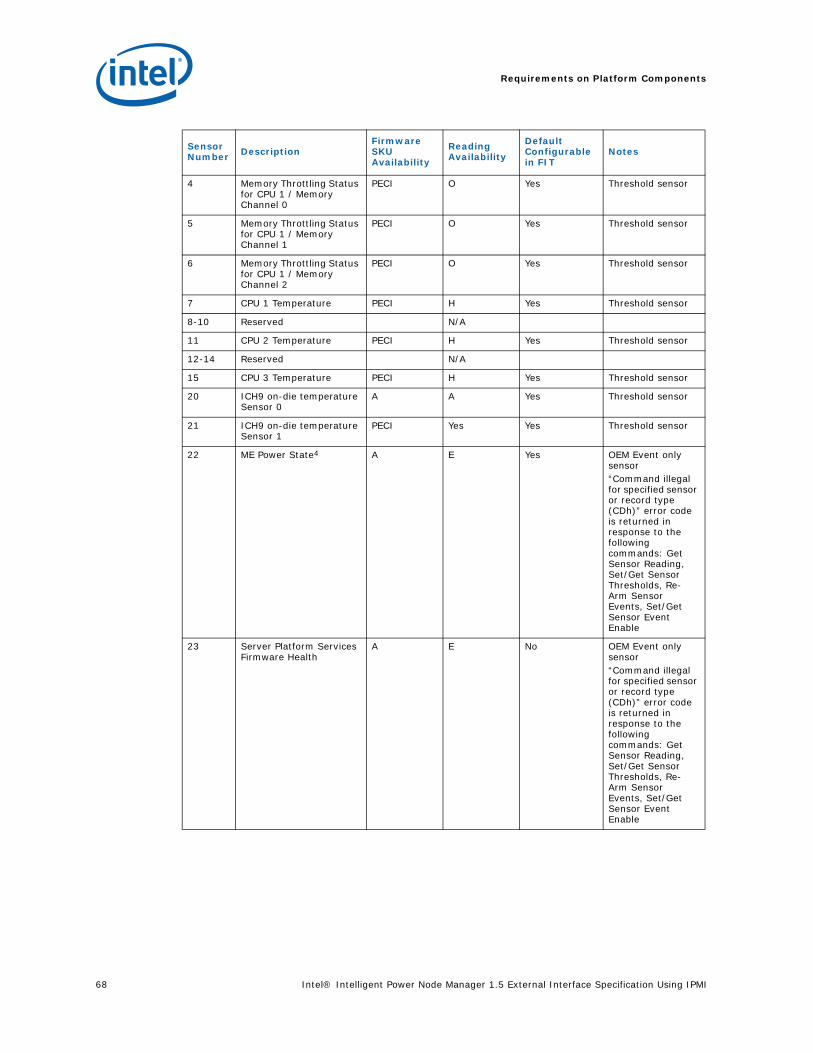
Requirements on Platform Components
68 Intel® Intelligent Power Node Manager 1.5 External Interface Specification Using IPMI
4 Memory Throttling Status for CPU 1 / Memory Channel 0
PECI O Yes Threshold sensor
5 Memory Throttling Status for CPU 1 / Memory Channel 1
PECI O Yes Threshold sensor
6 Memory Throttling Status for CPU 1 / Memory Channel 2
PECI O Yes Threshold sensor
7 CPU 1 Temperature PECI H Yes Threshold sensor
8-10 Reserved N/A
11 CPU 2 Temperature PECI H Yes Threshold sensor
12-14 Reserved N/A
15 CPU 3 Temperature PECI H Yes Threshold sensor
20 ICH9 on-die temperature Sensor 0
A A Yes Threshold sensor
21 ICH9 on-die temperature Sensor 1
PECI Yes Yes Threshold sensor
22 ME Power State4 A E Yes OEM Event only sensor“Command illegal for specified sensor or record type (CDh)” error code is returned in response to the following commands: Get Sensor Reading, Set/Get Sensor Thresholds, Re-Arm Sensor Events, Set/Get Sensor Event Enable
23 Server Platform Services Firmware Health
A E No OEM Event only sensor“Command illegal for specified sensor or record type (CDh)” error code is returned in response to the following commands: Get Sensor Reading, Set/Get Sensor Thresholds, Re-Arm Sensor Events, Set/Get Sensor Event Enable
Sensor Number Description
Firmware SKU Availability
Reading Availability
Default Configurable in FIT
Notes
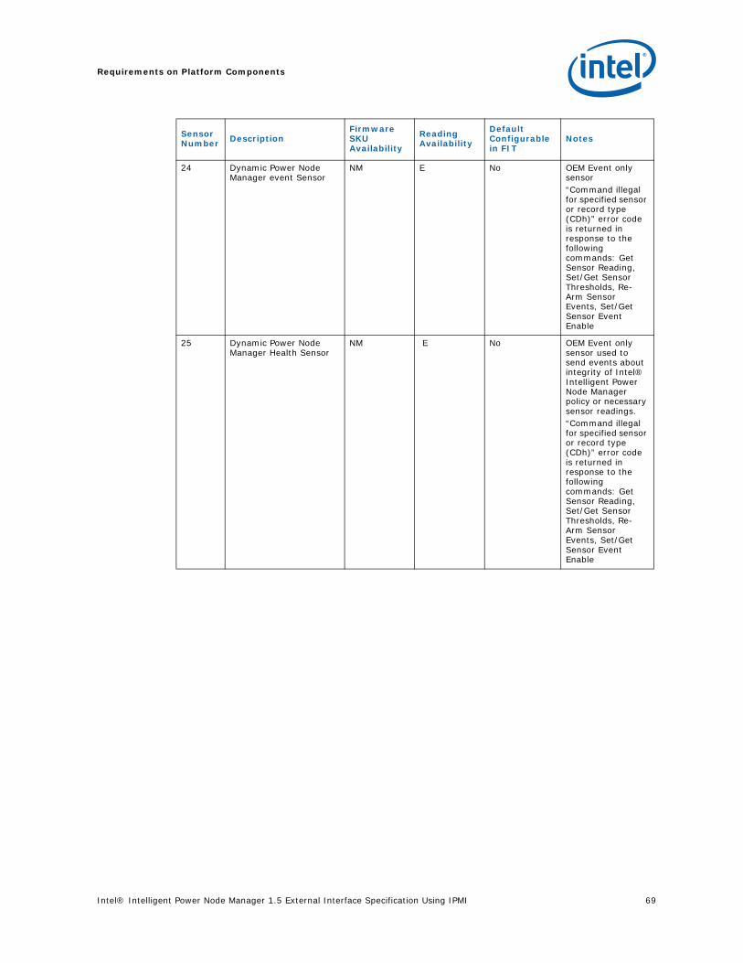
Intel® Intelligent Power Node Manager 1.5 External Interface Specification Using IPMI 69
Requirements on Platform Components
24 Dynamic Power Node Manager event Sensor
NM E No OEM Event only sensor“Command illegal for specified sensor or record type (CDh)” error code is returned in response to the following commands: Get Sensor Reading, Set/Get Sensor Thresholds, Re-Arm Sensor Events, Set/Get Sensor Event Enable
25 Dynamic Power Node Manager Health Sensor
NM E No OEM Event only sensor used to send events about integrity of Intel® Intelligent Power Node Manager policy or necessary sensor readings.“Command illegal for specified sensor or record type (CDh)” error code is returned in response to the following commands: Get Sensor Reading, Set/Get Sensor Thresholds, Re-Arm Sensor Events, Set/Get Sensor Event Enable
Sensor Number Description
Firmware SKU Availability
Reading Availability
Default Configurable in FIT
Notes
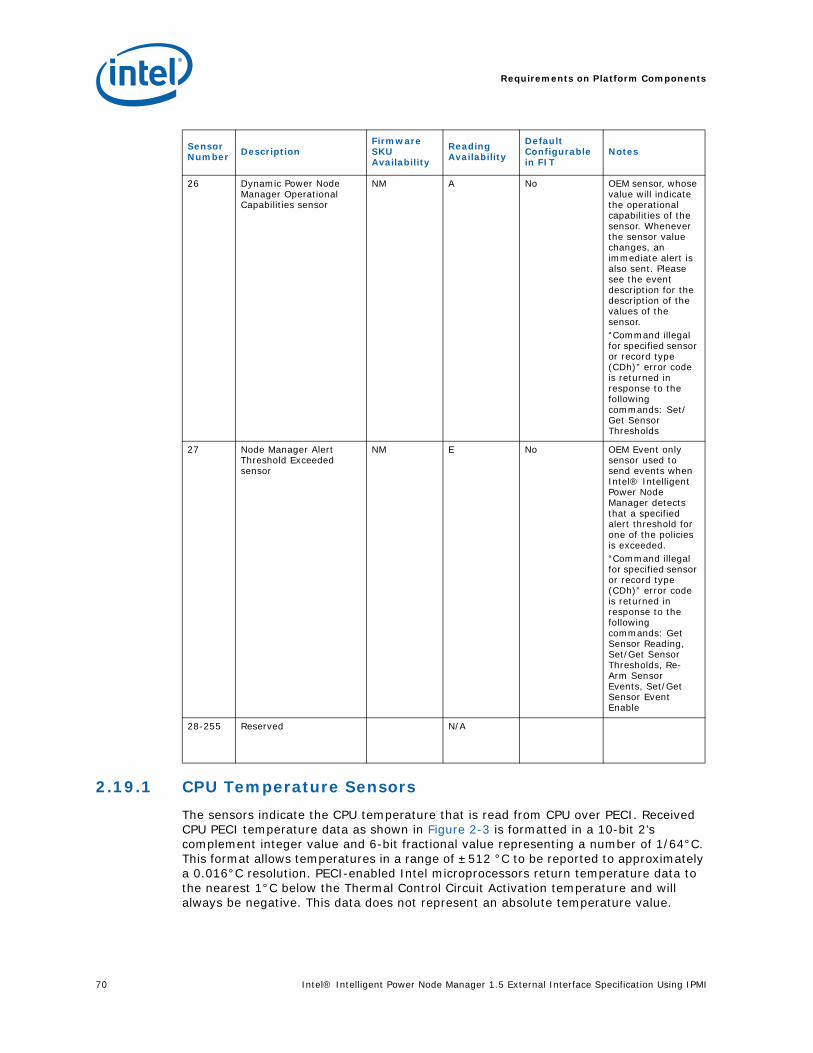
Requirements on Platform Components
70 Intel® Intelligent Power Node Manager 1.5 External Interface Specification Using IPMI
2.19.1 CPU Temperature Sensors
The sensors indicate the CPU temperature that is read from CPU over PECI. Received CPU PECI temperature data as shown in Figure 2-3 is formatted in a 10-bit 2’s complement integer value and 6-bit fractional value representing a number of 1/64°C. This format allows temperatures in a range of ±512 °C to be reported to approximately a 0.016°C resolution. PECI-enabled Intel microprocessors return temperature data to the nearest 1°C below the Thermal Control Circuit Activation temperature and will always be negative. This data does not represent an absolute temperature value.
26 Dynamic Power Node Manager Operational Capabilities sensor
NM A No OEM sensor, whose value will indicate the operational capabilities of the sensor. Whenever the sensor value changes, an immediate alert is also sent. Please see the event description for the description of the values of the sensor.“Command illegal for specified sensor or record type (CDh)” error code is returned in response to the following commands: Set/Get Sensor Thresholds
27 Node Manager Alert Threshold Exceeded sensor
NM E No OEM Event only sensor used to send events when Intel® Intelligent Power Node Manager detects that a specified alert threshold for one of the policies is exceeded. “Command illegal for specified sensor or record type (CDh)” error code is returned in response to the following commands: Get Sensor Reading, Set/Get Sensor Thresholds, Re-Arm Sensor Events, Set/Get Sensor Event Enable
28-255 Reserved N/A
Sensor Number Description
Firmware SKU Availability
Reading Availability
Default Configurable in FIT
Notes
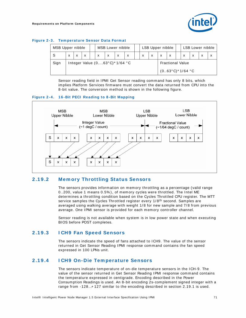
Intel® Intelligent Power Node Manager 1.5 External Interface Specification Using IPMI 71
Requirements on Platform Components
Figure 2-3. Temperature Sensor Data Format
Sensor reading field in IPMI Get Sensor reading command has only 8 bits, which implies Platform Services firmware must convert the data returned from CPU into the 8-bit value. The conversion method is shown in the following figure.
2.19.2 Memory Throttling Status Sensors
The sensors provides information on memory throttling as a percentage (valid range 0..200, value 1 means 0.5%), of memory cycles were throttled. The Intel ME determines a throttling condition based on the Cycles Throttled CPU register. The MTT service samples the Cycles Throttled register every 1/8th second. Samples are averaged using walking average with weight 1/8 for new sample and 7/8 from previous average. One IPMI sensor is provided for each memory controller channel.
Sensor reading is not available when system is in low power state and when executing BIOS before POST completes.
2.19.3 ICH9 Fan Speed Sensors
The sensors indicate the speed of fans attached to ICH9. The value of the sensor returned in Get Sensor Reading IPMI response command contains the fan speed expressed in 100 LPNs unit.
2.19.4 ICH9 On-Die Temperature Sensors
The sensors indicate temperature of on-die temperature sensors in the ICH-9. The value of the sensor returned in Get Sensor Reading IPMI response command contains the temperature expressed in centigrade. Encoding described in the Power Consumption Readings is used. An 8-bit encoding 2s-complement signed integer with a range from -128…+127 similar to the encoding described in section 2.19.1 is used.
MSB Upper nibble MSB Lower nibble LSB Upper nibble LSB Lower nibble
S x x x x x x x x x x x x x x x
Sign Integer Value (0....63°C)*1/64 °C Fractional Value
(0..63°C)*1/64 °C
Figure 2-4. 16-Bit PECI Reading to 8-Bit Mapping
Requirements on Platform Components
72 Intel® Intelligent Power Node Manager 1.5 External Interface Specification Using IPMI
2.19.5 Intel Management Engine Power State Sensor
This is an Event-Only sensor that does not support Get Sensor Reading command. The sensor is used to Platform Event messages to BMC when Intel ME power state is changing. The sensor uses Generic Event Reading code 0Ah. It supports only the offsets:
• 00h – Transition to Running – Intel ME is started
• 02h – Transition to Power Off - Intel ME is to be powered down
Optionally, instead of the event SPS Firmware may send an IPMI command with information as defined above. Using Factory presets OEM may choose to use an event or OEM command.
2.19.6 Dynamic Power Intel® Intelligent Power Node Manager Event Sensor
This is an Event-Only sensor that does not support Get Sensor Reading command nor re-arm IPMI command. The sensor is used in Platform Event messages to BMC when policy threshold or policy limit is exceeded.
2.19.7 Dynamic Power Intel® Intelligent Power Node Manager Health Sensor
OEM Event only sensor used to send events about integrity of Intel® Intelligent Power Node Manager policy or necessary sensor readings.
2.19.8 Dynamic Power Intel® Intelligent Power Node Manager Operational Capabilities sensor
OEM sensor, whose value will indicate the operational capabilities of the sensor. Whenever the sensor value changes, an immediate alert is also sent. Please see the event description for the description of the values of the sensor.
2.19.9 Server Platform Services Firmware Health Sensor
This is an Event-Only sensor that does not support Get Sensor Reading command nor re-arm IPMI command. The sensor is used in Platform Event messages to BMC containing health information including but not limited to FW Upgrade and application errors.

Intel® Intelligent Power Node Manager 1.5 External Interface Specification Using IPMI 73
Requirements on Platform Components
2.19.10 IPMI Platform Event Messages Generated by Platform Services FW
Intel ME Firmware will try to deliver the all the events by resenting them if event reception is not acknowledged by the BMC..
Event Sensor Type Event Dir Event Type Event Command
CPU Temperature 01h – temperature 0 – assertion1 – deassertion
01 – threshold Platform Event
ICH9 on-die temperature 01h – temperature 0 – assertion1 – deassertion
01 – threshold Platform Event
Memory Throttling Status
0Ch - Memory 0 – assertion1 – deassertion
01 – threshold Platform Event
ME Power State 16h – microcontroller
0 – assertion 0Ah – availability Platform Event
Node Manager Exception Event
DCh – OEM 0 – assertion 72h – OEM Platform Event
Node Manager Alert Threshold Exceeded sensor
DCh – OEM 0 – assertion1 – deassertion
72h - OEM Alert Immediate
Node Manager Health Event
DCh – OEM 0 – assertion 73h – OEM Alert Immediate
Node Manager Operational Capabilities Change Event
DCh – OEM 0 – assertion1 – deassertion
74h – OEM Alert Immediate
Server Platform Services Health Event
DCh – OEM 0 – assertion 75h – OEM Platform Event
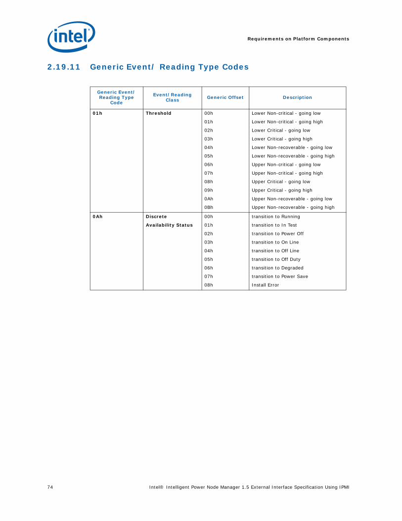
Requirements on Platform Components
74 Intel® Intelligent Power Node Manager 1.5 External Interface Specification Using IPMI
2.19.11 Generic Event/ Reading Type Codes
Generic Event/Reading Type
Code
Event/Reading Class Generic Offset Description
01h Threshold 00h
01h
02h
03h
04h
05h
06h
07h
08h
09h
0Ah
0Bh
Lower Non-critical - going low
Lower Non-critical - going high
Lower Critical - going low
Lower Critical - going high
Lower Non-recoverable - going low
Lower Non-recoverable - going high
Upper Non-critical - going low
Upper Non-critical - going high
Upper Critical - going low
Upper Critical - going high
Upper Non-recoverable - going low
Upper Non-recoverable - going high
0Ah Discrete
Availability Status
00h
01h
02h
03h
04h
05h
06h
07h
08h
transition to Running
transition to In Test
transition to Power Off
transition to On Line
transition to Off Line
transition to Off Duty
transition to Degraded
transition to Power Save
Install Error

Intel® Intelligent Power Node Manager 1.5 External Interface Specification Using IPMI 75
Requirements on Platform Components
2.19.12 Event Messages Definition
Net Function = S/E (0x4)
Code Command Request, Response Data Description
02h Platform Event MessageCPU Temperature
RequestByte 1 - EvMRev=04h (IPMI2.0 format)Byte 2 – Sensor Type=01h (temperature)Byte 3 – Sensor Number=3 CPU0 Temperature,=7 CPU1 Temperature,=11 CPU2 Temperature,=15 CPU3 Temperature,Byte 4 – Event Dir | Event Type[7] – Event Dir=0 Assertion Event, =1 Deassertion Event[6:0] – Event Type=01h (threshold sensor)Byte 5 – Event Data 1[7:6]=01b – trigger reading in byte 2[5: 4]=01b – trigger threshold in byte 3[3:0]= – offset from event type code:=<Value from 2.19.11 Generic Event/Reading Type Codes table>Byte 6 – Event Data 2=<CPU Temperature Sensor Reading Value>Byte 7 – Event Data 3=<CPU Temperature Sensor Threshold Value>
ResponseByte 1 – completion code=00h – Success (Remaining standard completion codes are shown in completion code section)
02h Platform Event MessageICH9 on-die temperature
RequestByte 1 - EvMRev=04h (IPMI2.0 format)Byte 2 – Sensor Type=01h (temperature)Byte 3 – Sensor Number=20 ICH9 on-die temperature Sensor 0,=21 ICH9 on-die temperature Sensor 1Byte 4 – Event Dir | Event Type[7] – Event Dir=0 Assertion Event, =1 Deassertion Event[6:0] – Event Type=01h (threshold sensor)Byte 5 – Event Data 1[7:6]=01b – trigger reading in byte 2[5:4]=01b – trigger threshold in byte 3[3:0]= – offset from event type code:=<Value from 2.19.11 Generic Event/Reading Type Codes table>Byte 6 – Event Data 2=<ICH9 on-die temperature Sensor Reading Value>Byte 7 – Event Data 3=<ICH9 on-die temperature Sensor Threshold Value>
ResponseByte 1 – completion code=00h – Success

Requirements on Platform Components
76 Intel® Intelligent Power Node Manager 1.5 External Interface Specification Using IPMI
02h Platform Event MessageMemory Throttling Status
RequestByte 1 - EvMRev=04h (IPMI2.0 format)Byte 2 – Sensor Type=0Ch (memory)Byte 3 – Sensor Number=<CPU#>*4+<Memory Channel#>,where: <CPU#>=[0,1,2,3]<Memory Channel#>=[0,1,2]Byte 4 – Event Dir | Event Type[7] – Event Dir=0 Assertion Event, =1 Deassertion Event[6:0] – Event Type=01h (threshold sensor)Byte 5 – Event Data 1[7:6]=01b – trigger reading in byte 2[5:4]=01b – trigger threshold in byte 3[3:0]= – offset from event type code:=<Value from 2.19.11 Generic Event/Reading Type Codes table>Byte 6 – Event Data 2=<Memory Throttling Status Sensor Reading Value>Byte 7 – Event Data 3=<Memory Throttling Status Sensor Threshold Value>
ResponseByte 1 – completion code=00h – Success (Remaining standard completion codes are shown in completion code section)
02h Platform Event MessageME Power State
Request Byte 1 - EvMRev=04h (IPMI2.0 format)Byte 2 – Sensor Type=16h (microcontroller)Byte 3 – Sensor Number=22 – ME Power StateByte 4 – Event Dir | Event Type[7] – Event Dir=0 Assertion Event,[6-0] – Event Type=0Ah (Availability Status)Byte 5 – Event Data 1[7,6]=00b – unspecified byte 2[5,4]=00b – unspecified byte 3[3..0] – offset from event type code:=00h – Transition to running=02h – Transition to Power Off
Note: This sensor can be disabled using Factory Image Tool so the OEM command will be used instead see 3.4.4 OEM ME Power State Change
ResponseByte 1 – completion code=00h – Success (Remaining standard completion codes are shown in completion code section)
02h Platform Event MessageNode Manager Exception Event
For event description see see Section 2.3
Net Function = S/E (0x4)
Code Command Request, Response Data Description

Intel® Intelligent Power Node Manager 1.5 External Interface Specification Using IPMI 77
Requirements on Platform Components
02h Platform Event MessageNode Manager Health Event
For event description see Section 2.3
02h Platform Event MessageNode Manager Operational Capabilities Change
For event description see Section 2.3
02h Platform Event MessageNode manager Alert Threshold Exceeded
For event description see Section 2.3
Net Function = S/E (0x4)
Code Command Request, Response Data Description

Requirements on Platform Components
78 Intel® Intelligent Power Node Manager 1.5 External Interface Specification Using IPMI
2.20 Event Generation ControlThe below table summarizes how event generation can be enabled/disabled for each sensor implemented by Intel® Intelligent Power Node Manager Firmware.
02h Platform Event MessageServer Platform Services Firmware Health Event
Request Byte 1 - EvMRev=04h (IPMI2.0 format)Byte 2 – Sensor Type=DCh (OEM)Byte 3 – Sensor Number=23 – Server Platform Services Firmware HealthByte 4 – Event Dir | Event Type[7] – Event Dir=0 Assertion Event[6-0] – Event Type=75h (OEM)Byte 5 – Event Data 1[7,6]=10b – OEM code in byte 2[5,4]=10b – OEM code in byte 3[3..0] – Health Event Type=00h –Firmware StatusByte 6 – Event Data 2=0 - Forced GPIO recovery. Recovery Image loaded due to Magpie> (default recovery pin is MGPIO1) pin asserted. Repair action: Dessert MGPIO1 and reset the Intel ME=1 - Image execution failed. Recovery Image loaded because operational image is corrupted. This may be either caused by Flash device corruption or failed upgrade procedure. Repair action: Either the Flash device must be replaced (if error is persistent) or the upgrade procedure must be started again.=2 - Flash erase error. Error during Flash erases procedure probably due to Flash part corruption.Repair action: The Flash device must be replaced.=3 – Flash corrupted. Error while checking Flash consistency probably due to Flash part corruption.Repair action: The Flash device must be replaced (if error is persistent).=4 – Internal error. Error during firmware execution. FW Watchdog Timeout.Repair action: : Operational image shall be upgraded to other version or hardware board repair is needed (if error is persistent). = 5 – BMC did not responded to cold reset request and Intel ME rebooted the platformRepair action: Verify the Node Manager configuration.=6..255 – Reserved Byte 7 – Event Data 3=<Extended error code. Should be used when reporting an error to the support>
This platform event provides a run-time status of general Firmware status. Recovery from the errors may require Intel ME reset or even FW upgrade or HW repair if the error is persistent.
Note: This sensor can not be disabled using Factory Image Tool.
ResponseByte 1 – completion code=00h – Success (Remaining standard completion codes are shown in completion code section)
Net Function = S/E (0x4)
Code Command Request, Response Data Description

Intel® Intelligent Power Node Manager 1.5 External Interface Specification Using IPMI 79
Requirements on Platform Components
2.20.1 Server Platform Services Debug Event
After recovery from Intel Management Engine system error. Intel Management Engine firmware generates Add SEL entry command with debug information about the error. Purpose of this message is solely in field debugging, it is not intended to replace health sensor events. It is recommended that BMC shall support storing the SEL records passed in the Add SEL Entry command. By assumption debug event does not contain any sensitive information. Generation of this event may be disabled in flash configuration. It is recommended to disable debug event generation in the firmware loaded on the platforms shipped the end customer.
Event is repeated every 5s until Intel® Intelligent Power Node Manager receives response with Success completion code.
2.20.2 Debug SEL Entry Definition (External)
Debugging information in the message is intended to be used only by Intel Corporation engineering team. Since internal structure definition may be subject of changes any support request should contain both message content and firmware revision (it is not embedded in message due to space constrains).
Sensor Type IPMI Command Event Generation Control Methods
CPU Temperature Sensors
ICH Temperature Sensors
Memory Throttling Sensors
Platform Event Event generation can be enabled/disabled using the IPMI commands:
• Set Event Receiver• Set Event Enable - both per sensor and per threshold control
support
Default event enable flags can be set using Flash Image Tool for each threshold.
ME Power State Sensor Platform Event or OEM command (settable using FIT)
When the notification is sent using Platform Event message, event generation can be enabled/disabled using the IPMI commands:
• Set Event Receiver
If the event is sent using OEM message, the notification is sent always to address 20h regardless of the Event Receiver settings.
Node Manager Exception Sensor
Platform Event Event generation can be enabled/disabled using the IPMI commands:
• Set Event Receiver
Node Manager Operational Capabilities Sensor
Alert Immediate Event generation can be enabled/disabled using the IPMI commands:
• Set Node Manager Alert Destination – clearing alert destination parameters disables generation of events sent using Alert Immediate IPMI command
• Set Event Enable – Scanning Enabled bit disables/enables the whole sensor.
• Changing per sensor Event Enable flag is supported.
Node Manager Health Sensor
Node Manager Alert Threshold Exceeded Sensor
Alert Immediate Event generation can be enabled/disabled using the IPMI commands:
• Set Node Manager Alert Destination – clearing alert destination parameters disables generation of events sent using Alert Immediate IPMI command
SPS FW Health Sensor Platform Event Not possible to enable/disable event generation from this sensor
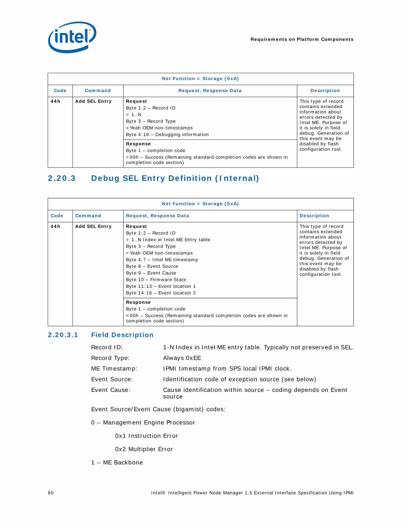
Requirements on Platform Components
80 Intel® Intelligent Power Node Manager 1.5 External Interface Specification Using IPMI
2.20.3 Debug SEL Entry Definition (Internal)
2.20.3.1 Field Description
Record ID: 1-N Index in Intel ME entry table. Typically not preserved in SEL.
Record Type: Always 0xEE
ME Timestamp: IPMI timestamp from SPS local IPMI clock.
Event Source: Identification code of exception source (see below)
Event Cause: Cause identification within source – coding depends on Event source
Event Source/Event Cause (bigamist) codes:
0 – Management Engine Processor
0x1 Instruction Error
0x2 Multiplier Error
1 – ME Backbone
Net Function = Storage (0xA)
Code Command Request, Response Data Description
44h Add SEL Entry RequestByte 1:2 – Record ID= 1..NByte 3 – Record Type=Yeah OEM non-timestampsByte 4:16 – Debugging information
This type of record contains extended information about errors detected by Intel ME. Purpose of it is solely in field debug. Generation of this event may be disabled by flash configuration tool.
ResponseByte 1 – completion code=00h – Success (Remaining standard completion codes are shown in completion code section)
Net Function = Storage (0xA)
Code Command Request, Response Data Description
44h Add SEL Entry RequestByte 1:2 – Record ID= 1..N Index in Intel ME Entry tableByte 3 – Record Type=Yeah OEM non-timestampsByte 4:7 – Intel ME timestampByte 8 – Event SourceByte 9 – Event CauseByte 10 – Firmware StateByte 11:13 – Event location 1Byte 14:16 – Event location 2
This type of record contains extended information about errors detected by Intel ME. Purpose of it is solely in field debug. Generation of this event may be disabled by flash configuration tool.
ResponseByte 1 – completion code=00h – Success (Remaining standard completion codes are shown in completion code section)

Intel® Intelligent Power Node Manager 1.5 External Interface Specification Using IPMI 81
Requirements on Platform Components
0x1 Illegal Memory Cycle
0x2 Illegal Config Cycle
0x4 DRAM Access in Wrong Power-State
2 – Non-posted completion timer
0x1 Non-Posted Completion Timeout
3 – MLINK
0x1 Link Fatal Error
4 – Firmware Watchdog
0x8 Watchdog Timer Expiration
Firmware State:State of the firmware when event occurred.
Content below is only for reference (PM is currently redefining information format)
// Estate field values
#define OS_PM_ME_STATE_M0 0
#define OS_PM_ME_STATE_M1 1
// Host Power State field values
#define OS_PM_HOST_PWR_STATE_S0 0
#define OS_PM_HOST_PWR_STATE_S1 1
#define OS_PM_HOST_PWR_STATE_S2 2
#define OS_PM_HOST_PWR_STATE_S3 3
#define OS_PM_HOST_PWR_STATE_S4 4
#define OS_PM_HOST_PWR_STATE_S5 5
// HostSwState field values
#define OS_PM_HOST_SW_STATE_POST 0
#define OS_PM_HOST_SW_STATE_OS_PRESENT 1
Event Location 1: Three low order bytes from exception address (ILINK3 register)
Event Location 2: Three low order bytes from last procedure return address (ILINK1 register)
2.21 Completion CodesPlatform Services firmware IPMI commands use standard completion codes from table below and specific OEM commands codes if specified in command description.
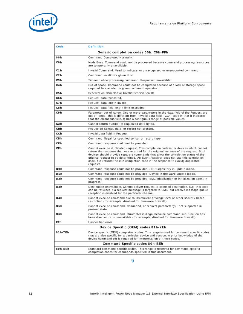
Requirements on Platform Components
82 Intel® Intelligent Power Node Manager 1.5 External Interface Specification Using IPMI
§
Code Definition
Generic completion codes 00h, C0h-FFh
00h Command Completed Normally.
C0h Node Busy. Command could not be processed because command processing resources are temporarily unavailable.
C1h Invalid Command. Used to indicate an unrecognized or unsupported command.
C2h Command invalid for given LUN.
C3h Timeout while processing command. Response unavailable.
C4h Out of space. Command could not be completed because of a lack of storage space required to execute the given command operation.
C5h Reservation Canceled or Invalid Reservation ID.
C6h Request data truncated.
C7h Request data length invalid.
C8h Request data field length limit exceeded.
C9h Parameter out of range. One or more parameters in the data field of the Request are out of range. This is different from ‘Invalid data field’ (CCh) code in that it indicates that the erroneous field(s) has a contiguous range of possible values.
CAh Cannot return number of requested data bytes.
CBh Requested Sensor, data, or record not present.
CCh Invalid data field in Request
CDh Command illegal for specified sensor or record type.
CEh Command response could not be provided.
CFh Cannot execute duplicated request. This completion code is for devices which cannot return the response that was returned for the original instance of the request. Such devices should provide separate commands that allow the completion status of the original request to be determined. An Event Receiver does not use this completion code, but returns the 00h completion code in the response to (valid) duplicated requests.
D0h Command response could not be provided. SDR Repository in update mode.
D1h Command response could not be provided. Device in firmware update mode.
D2h Command response could not be provided. BMC initialization or initialization agent in progress.
D3h Destination unavailable. Cannot deliver request to selected destination. E.g. this code can be returned if a request message is targeted to SMS, but receive message queue reception is disabled for the particular channel.
D4h Cannot execute command due to insufficient privilege level or other security based restriction (for example, disabled for ‘firmware firewall’).
D5h Cannot execute command. Command, or request parameter(s), not supported in present state.
D6h Cannot execute command. Parameter is illegal because command sub-function has been disabled or is unavailable (for example, disabled for ‘firmware firewall’).
FFh Unspecified error.
Device Specific (OEM) codes 01h-7Eh
01h-7Eh Device specific (OEM) completion codes. This range is used for command specific codes that are also specific for a particular device and version. A prior knowledge of the device command set is required for interpretation of these codes.
Command Specific codes 80h-BEh
80h-BEh Standard command-specific codes. This range is reserved for command specific completion codes for commands specified in this document.

Intel® Intelligent Power Node Manager 1.5 External Interface Specification Using IPMI 83
BMC IPMI Interface
3 BMC IPMI Interface
This section contains IPMI commands and sensor devices which shall be provided by BMC in order to enable Platform Services firmware.
To support initialization of Intel ME-owned sensors based on associated SDRs, OEM BMC must be able to use both the slave-address and BMC channel number fields of the type1 and type2 SDRs for the purpose of directing the IPMI sensor commands to the Intel ME.
3.1 IPMI Device “Global” Commands
3.2 Sensor Device Commands
Net Function = Storage (0x0)
Code Command Request, Response Data Description
02h Chassis Control Command
RequestByte 1 - [7:4] – Reserved. Write as 0000b.[3:0] – Control Command=0 – power down=5 – soft shutdown (via ACPI) (optional)
This is standard IPMI 2.0 command.
Note: SPS Firmware will use Soft Shutdown (optional) and Power Down.
ResponseByte 1 – completion code=00h – Success (Remaining standard completion codes are shown in completion code section)
Net Function = Storage (0xA), LUN = 00b
Code Command Request, Response Data Description
02h Platform Event Message
For command description see [IPMI] This is general format of Platform Event Message. Detailed description ofall messages generated by Platform Services firmware can be found in section, IPMI Platform Event Messages generated by Platform Services FW.
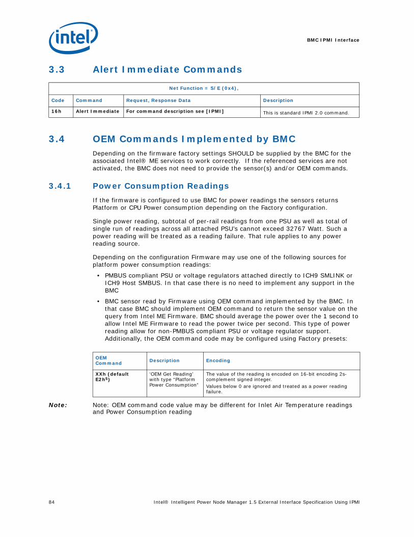
BMC IPMI Interface
84 Intel® Intelligent Power Node Manager 1.5 External Interface Specification Using IPMI
3.3 Alert Immediate Commands
3.4 OEM Commands Implemented by BMCDepending on the firmware factory settings SHOULD be supplied by the BMC for the associated Intel® ME services to work correctly. If the referenced services are not activated, the BMC does not need to provide the sensor(s) and/or OEM commands.
3.4.1 Power Consumption Readings
If the firmware is configured to use BMC for power readings the sensors returns Platform or CPU Power consumption depending on the Factory configuration.
Single power reading, subtotal of per-rail readings from one PSU as well as total of single run of readings across all attached PSU’s cannot exceed 32767 Watt. Such a power reading will be treated as a reading failure. That rule applies to any power reading source.
Depending on the configuration Firmware may use one of the following sources for platform power consumption readings:
• PMBUS compliant PSU or voltage regulators attached directly to ICH9 SMLINK or ICH9 Host SMBUS. In that case there is no need to implement any support in the BMC
• BMC sensor read by Firmware using OEM command implemented by the BMC. In that case BMC should implement OEM command to return the sensor value on the query from Intel ME Firmware. BMC should average the power over the 1 second to allow Intel ME Firmware to read the power twice per second. This type of power reading allow for non-PMBUS compliant PSU or voltage regulator support. Additionally, the OEM command code may be configured using Factory presets:
Note: Note: OEM command code value may be different for Inlet Air Temperature readings and Power Consumption reading
Net Function = S/E (0x4),
Code Command Request, Response Data Description
16h Alert Immediate For command description see [IPMI] This is standard IPMI 2.0 command.
OEMCommand Description Encoding
XXh (default E2h5)
‘OEM Get Reading’ with type “Platform Power Consumption”
The value of the reading is encoded on 16-bit encoding 2s-complement signed integer.Values below 0 are ignored and treated as a power reading failure.

Intel® Intelligent Power Node Manager 1.5 External Interface Specification Using IPMI 85
BMC IPMI Interface
3.4.2 Inlet Air Temperature Readings
Depending on the configuration Firmware may use one of the following sources for inlet temperature readings:
• SST sensors attached directly to ICH9. In that case there is no need to implement any support in the BMC
• BMC sensor read by Firmware using OEM command implemented by the BMC. In that case BMC should implement OEM command to return the sensor value on the query from Intel ME Firmware. Additionally, the OEM command code may be configured using Factory presets:
Note: 6OEM command code value may be different for Inlet Air Temperature readings and Power Consumption reading.
• Get Sensor Reading IPMI command. Intel ME Firmware expects the sensor reading to be temperature in range of 0 to 100 centigrade. Sensor readings outside of the specified range are ignored and treated as a temperature reading failure.
• Inlet Air Temperature reading can be disabled. In that case the inlet temperature statistics and Node Manager Policies using temperature trigger will be not available.
OEMCommand Description Encoding
XXh (default E2h6)
‘OEM Get Reading’ with type “Inlet Air Temperature”
The value of the sensor returned in Get Inlet Air Temperature is encoded on 16-bit encoding 2s-complement signed integerValues below -128 degrees centigrade and above +127 degrees centigrade are ignored and treated as a temperature reading failure.
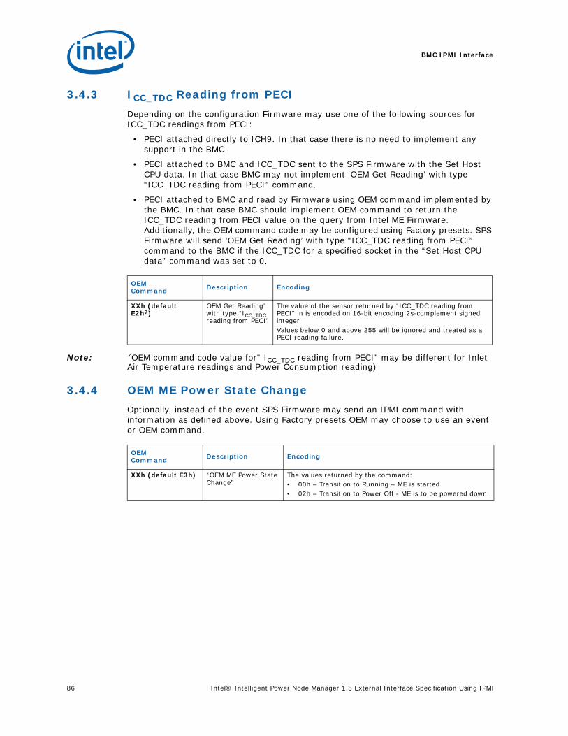
BMC IPMI Interface
86 Intel® Intelligent Power Node Manager 1.5 External Interface Specification Using IPMI
3.4.3 ICC_TDC Reading from PECI
Depending on the configuration Firmware may use one of the following sources for ICC_TDC readings from PECI:
• PECI attached directly to ICH9. In that case there is no need to implement any support in the BMC
• PECI attached to BMC and ICC_TDC sent to the SPS Firmware with the Set Host CPU data. In that case BMC may not implement ‘OEM Get Reading’ with type “ICC_TDC reading from PECI” command.
• PECI attached to BMC and read by Firmware using OEM command implemented by the BMC. In that case BMC should implement OEM command to return the ICC_TDC reading from PECI value on the query from Intel ME Firmware. Additionally, the OEM command code may be configured using Factory presets. SPS Firmware will send ‘OEM Get Reading’ with type “ICC_TDC reading from PECI” command to the BMC if the ICC_TDC for a specified socket in the “Set Host CPU data” command was set to 0.
Note: 7OEM command code value for” ICC_TDC reading from PECI” may be different for Inlet Air Temperature readings and Power Consumption reading)
3.4.4 OEM ME Power State Change
Optionally, instead of the event SPS Firmware may send an IPMI command with information as defined above. Using Factory presets OEM may choose to use an event or OEM command.
OEMCommand Description Encoding
XXh (default E2h7)
OEM Get Reading’ with type “ICC_TDC reading from PECI”
The value of the sensor returned by “ICC_TDC reading from PECI” in is encoded on 16-bit encoding 2s-complement signed integerValues below 0 and above 255 will be ignored and treated as a PECI reading failure.
OEMCommand Description Encoding
XXh (default E3h) “OEM ME Power State Change”
The values returned by the command:• 00h – Transition to Running – ME is started• 02h – Transition to Power Off - ME is to be powered down.

Intel® Intelligent Power Node Manager 1.5 External Interface Specification Using IPMI 87
BMC IPMI Interface
3.4.5 OEM Command Definition
Net Function = SDK General Application(0x30)
Code Command Request, Response Data Description
E2h OEM Get Reading RequestByte 1 – Domain Id/Reading Type[0:3] = Domain Id (depending on the Byte 2 identifies the processor which should be queried for ICC_TDC or power rail)[4:7] = Reading Type=00h – Platform Power Consumption. For platform power consumption the Domain Id will be set to 0. Values from 1 to 15 could be used to address power rails. Per-rail readings are optional and Firmware needs to be preconfigured in the factory settings. =01h – Inlet Air Temperature. For Inlet Air Temperature the Domain Id will be set to 0.=02h – ICC_TDC reading from PECI. For ICC_TDC reading from PECI the Domain Id address the processor socket and the range from 0 to number of installed CPUs/socket. Number of installed CPUs is set by the Set Host CPU data command byte 5.=03h...0Fh - reservedBytes 3:2 – reserved. Write as 0000h
This command is optional and may be implemented by the BMC.
ResponseByte 1 – completion code=00h – Success(Remaining standard completion codes are shown in completion code section)Byte 2 – Reading Type[0:3] = Domain Id copied from request (depending on the Byte 2 identifies the processor which should be queried for ICC_TDC or power rail)[4:7] = Reading Type=00h – Platform Power Consumption in Watts. Values below 0 are ignored and treated as a power reading failure.=01h – Inlet Air Temperature in degrees centigrade. Values below -128 degrees centigrade and above +127 degrees centigrade will be ignored and treated as a temperature reading failure. =02h – ICC_TDC reading from PECI. Values below 0 and above 255 will be ignored and treated as a PECI reading failure. =03h...FFh - reservedBytes 4:3 – Reading value 16-bit encoding 2s-complement signed integer
E3h OEM ME Power State Change
RequestByte 1 – Power State:=00h – Transition to Running – ME is started=02h – Transition to Power Off - ME is to be powered down.
This command is optional and may be implemented by the BMC.
ResponseByte 1 – completion code=00h – Success(Remaining standard completion codes are shown in completion code section)

BMC IPMI Interface
88 Intel® Intelligent Power Node Manager 1.5 External Interface Specification Using IPMI
3.4.6 Summary of Options
3.4.7 IPMI Command Bridging
BMC code should allow restricting the privilege level to access to the Intel ME SMLINK channel IPMI command bridging only for the Admin level.
3.4.8 IPMB Reset Scenarios
BMC and Intel ME Firmware share the same SMBUS link. The Intel ME Firmware will perform SMBUS hang recovery only when the hang happens during a transaction initiated by Intel ME. The recovery method is by “bit banging” 9 clock pulses. The Intel ME FW does not reset SMLINK on startup.
§
Summary of Implementation Options
Functionality Type Description
Power Consumption readings
Factory presets Power readings via OEM Get Reading command are only needed if no PMBUS PSU is directly connected to the SMLINK. Default in the Factory Presets is to use PMBUS PSU.
Inlet Air Temperature readings
Factory preset Required if inlet temperature statistics and Node Manager Policies using temperature trigger will be exposed by the platform.
ICC_TDC reading from PECI
Runtime dependency ICC_TDC reading is required for NM to operate. Can be sent by BMC with Set Host CPU data. If the ICC_TDC will not be provided by BMC with the Set Host CPU data after reception of end of POST notification Intel ME Firmware will query the BMC using OEM Get Reading command.
OEM ME Power State Change
Factory presets Intel ME Firmware is able to send notification about the power state change using standard IPMI sensor or via OEM command.Default is to use OEM command.