extraction with reflux for type ii systems · 3. why is the design of extraction with reflux for...
TRANSCRIPT

1
Extraction with Reflux for Type II Systems
All rights reserved, Armando B. Corripio, PhD, PE, 2014
Contents Extraction with Reflux for Type II Systems..................... 1
1 Use Solvent-free Basis for the Calculations ................ 3
2 Extraction of Type II Systems with Reflux .................. 6
3 Over-all Mass Balances ..................................... 8
4 Operating Lines ............................................ 8
Example 1. Design of an Extraction Column of a Type II System
with Reflux ............................................... 10
Summary ..................................................... 12
Review Questions ............................................ 12
There is a type of systems with a different solubility chart
from the Type I systems studied in the previous lecture notes.
They are called Type II systems and their solubility charts have
the following form:

2
Figure 1. Solubility chart for a Type II system
In this system the solute is MCH (methyl-cyclo-hexane), the
diluent is n-heptane, and the solvent is aniline.
The main difference from Type II systems is that there is
no plait point, that is, the two-phase region extends from the
AS axis to the SB axis. Notice that there is a tie line
coinciding with the AS axis with points xB = 0, yB = 0, and one
coinciding with the SB axis with points xA = 0, yA = 0. Notice
also that the solvent and the solute are only partially miscible
with each other. This should surprise you as the solvent is used
to extract the solute even it is not even completely soluble in
it.

3
As we shall see, it is possible to produce very pure
extracts (on a solvent-free basis) by arranging two extraction
batteries and returning some of the extract as reflux. The idea
is borrowed from distillation and will show you that one of your
jobs as a chemical engineer is to transfer ideas from one
application to another.
1 Use Solvent-free Basis for the Calculations
The calculations for Type I systems are greatly simplified if
they are carried out on a solvent-free basis. The following
formulas convert mass fractions into solvent-free fractions:
(1)
On a solvent-free basis it is not necessary to differentiate
between components A and B because only one composition is
required to represent a stream. The fractions of diluent are (1
– X) and (1 – Y), and the solvent is expressed as mass of
solvent per mass of solvent-free solution, calculated by
(2)
The equilibrium data of Figure 1, taken from the MCH mass
fraction at the end of the tie lines, can be plotted on solvent-
free basis as follows:

4
Figure 2. Equilibrium data for MCH-heptane-aniline on solvent-free basis
Similarly, the solubility of aniline in the raffinate from
Figure 1 can be plotted on solvent-free basis:
0.000
0.100
0.200
0.300
0.400
0.500
0.600
0.700
0.800
0.900
1.000
0.000 0.100 0.200 0.300 0.400 0.500 0.600 0.700 0.800 0.900 1.000
YA
, mas
s fr
acti
on
MC
H in
ext
ract
, so
lve
nt
-fre
e
XA, mass fraction MCH in raffinate, solvent-free

5
Figure 3. Solubility of aniline in the raffinate on solvent-free basis
The mass of solvent carried by unit mass of solvent-free extract
can also be determined from Figure 1:
0.060
0.070
0.080
0.090
0.100
0.110
0.120
0.130
0.140
0.000 0.200 0.400 0.600 0.800 1.000 1.200
XS,
mas
s o
f an
ilin
e p
er
mas
s o
f an
ilin
e-f
ree
raf
fin
ate
XA, mass fraction MCH in raffinate, solvent-free
XS vs XA
6
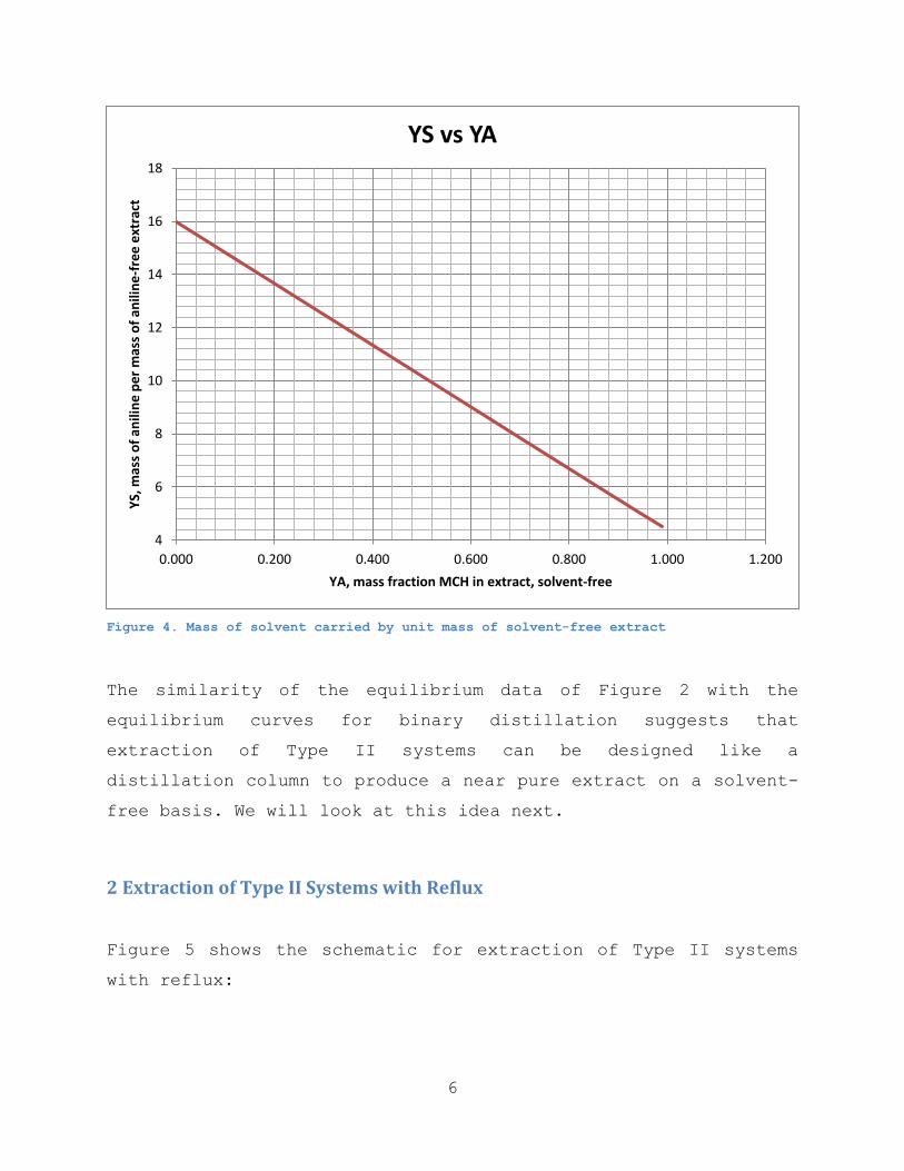
Figure 4. Mass of solvent carried by unit mass of solvent-free extract
The similarity of the equilibrium data of Figure 2 with the
equilibrium curves for binary distillation suggests that
extraction of Type II systems can be designed like a
distillation column to produce a near pure extract on a solvent-
free basis. We will look at this idea next.
2 Extraction of Type II Systems with Reflux
Figure 5 shows the schematic for extraction of Type II systems
with reflux:
4
6
8
10
12
14
16
18
0.000 0.200 0.400 0.600 0.800 1.000 1.200
YS,
mas
s o
f an
ilin
e p
er
mas
s o
f an
ilin
e-f
ree
ext
ract
YA, mass fraction MCH in extract, solvent-free
YS vs YA

7
EXE
FXF
RXR
SolventIn
SolventOut
V1
Y1
L
Figure 5. Extraction of a Type II system with reflux
The bottom box in Figure 5 is a countercurrent contact column
with the feed entering at the top of this box; the solvent
enters at the bottom and the raffinate R leaves at the bottom.
The other stream leaving this bottom box is the extract; this is
fed to the top box which is another countercurrent contact
column. The extract V1 leaving the top column is fed to a
distillation column where the solvent is separated from it
producing a top product E which is the extract actually free of
solvent. Part of this extract is the reflux L fed to the top
column to remove the diluent from the stream flowing up. The
solvent removed by the distillation column at the top is
recycled back and makes up the majority of the solvent entering
at the bottom. Only the solvent dissolved in the raffinate R is

8
lost and must be replaced with fresh solvent. The complete
operation is simply a single column with the portion above the
feed is called the extract-enriching section and the portion
below the feed called the raffinate-stripping section.
You are encouraged to study Figure 5 and recognize the
following parallels between stripping with reflux and
distillation:
Stripping with Reflux Distillation
Extract phase flow Vapor flow
Raffinate phase flow Liquid flow
Solvent removal column Condenser
Extract-enriching section Rectifying section
Raffinate-stripping section Stripping section
Solvent added at bottom Heat to reboiler
Solvent-free feed Saturated-liquid feed
3 Over-all Mass Balances
From Figure 4 we can write the following over-all mass balances
on a solvent-free basis:
Total mass balance: F = E + R (3)
Balance on the condenser: V1 = E + L (5)
4 Operating Lines
The enriching operating line is obtained from a solute balance
around n stages in the extract-enriching section:

9
(6)
Where Ln = Vn+1 – E, and Vn+1 is determined from the solvent
balance:
(7)
Similarly, the stripping operating line results from a
solute balance on m stages in the raffinate-stripping section:
(8)
Where Lm = Vm+1 + R, and Vm+1 is determined from the solvent
balance:
(9)
Equations (7) and (9) must be solved by iteration. The
assumption of equi-mass counter-diffusion results in constant
phase flows in each section and straight operating lines. At the
feed tray the flows change as follows:
Lm = Ln + F (10)
Where Lm and Ln are the raffinate phase flows in the stripping
and enriching sections, respectively, and the extract phase flow
does not change at the feed plate.

10
EXE
FXF
RXR
SolventIn
SolventOut
V1
Y1
L
Example 1. Design of an Extraction Column of a Type II System with Reflux
A solution of 45 weight% methyl-cyclo-hexane (MCH) and the
balance heptane is fed to a column to extract 96% of the MCH and
produce an extract product with no more than 3 weight% heptane
on a solvent-free basis. The solvent is aniline. An extract-
enriching section is used with a reflux to extract product ratio
of 3. Determine the number of equilibrium stages required and
the location of the feed tray. Report also how much solvent must
be fed at the bottom and the make-up solvent required if the
solvent recovered from the extract is recycled.
Solution.
Basis: F = 100 kg
XF = 45%
96% Recovery of MCH
XE = (100 – 3)% = 97%
L/E = 3
Recovery of MCH:
( )( )
Total mass balance:
R = F – E = 100 – 44.5
= 55.5 kg

11
Solute balance:
( )( ) ( )( )
Reflux flow: L = 3E = 3(44.5) = 133.5 kg
Extract flow: V1 = L + E = 133.5 + 44.5 = 178.0 kg
Intercept of enriching operating line on Y-axis:
( )( )
The McCabe-Thiele solution, assuming constant phase flows in
each section (straight operating lines) results in 20
equilibrium stages, 10 in each section. The feed line is always
vertical on a solvent-free basis.
From Figure 4, the solvent leaving with the extract at Y1 =
XE = 0.97 contains YS = 4.8 kg aniline/kg aniline-free extract.
So, the aniline that must be removed by distillation is:
0%
10%
20%
30%
40%
50%
60%
70%
80%
90%
100%
0% 10% 20% 30% 40% 50% 60% 70% 80% 90% 100%
MCH in raffinate, solvent free
MC
H in
extr
act,
so
lven
t fr
ee

12
V1YS = (178.0)(4.8) = 854.4 kg
From Figure 3, the solvent leaving with the raffinate at XR
= 0.0324 contains XS = 0.076 kg aniline/kg of aniline-free
raffinate. So, the amount of aniline lost with the raffinate is:
RXS = (55.5)(0.076) = 4.2 kg
Total aniline to be fed at the bottom: 854.4 + 4.2 = 858.6 kg
Of this, 854.4 kg are recycled and 4.2 kg must be made up with
fresh solvent. All these values are on the basis of 100 kg of
feed.
Summary
These notes have shown how an extraction column with recycle can
be designed to produce a purer extract than with a simple
extraction column. The design is very similar to the design of a
binary distillation column when the calculations are carried out
on a solvent-free basis. Extraction with reflux can only be
carried out with Type II systems. This is because Type I systems
have a plait point in their solubility chart. The plait point is
similar to an azeotrope in distillation making it impossible to
produce a pure extract by extraction.
Review Questions
13
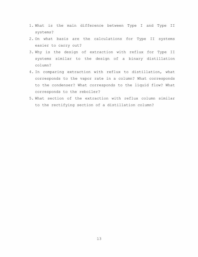
1. What is the main difference between Type I and Type II
systems?
2. On what basis are the calculations for Type II systems
easier to carry out?
3. Why is the design of extraction with reflux for Type II
systems similar to the design of a binary distillation
column?
4. In comparing extraction with reflux to distillation, what
corresponds to the vapor rate in a column? What corresponds
to the condenser? What corresponds to the liquid flow? What
corresponds to the reboiler?
5. What section of the extraction with reflux column similar
to the rectifying section of a distillation column?