fabrication of a three-dimensional micro-manipulator by
TRANSCRIPT

Instructions for use
Title Fabrication of a three-dimensional micro-manipulator by laser irradiation and electrochemical techniques and the effectof electrolytes on its performance
Author(s) Kikuchi, T.; Akiyama, Y.; Ueda, M.; Sakairi, M.; Takahashi, H.
Citation Electrochimica Acta, 52(13), 4480-4486https://doi.org/10.1016/j.electacta.2006.12.043
Issue Date 2007-03-20
Doc URL http://hdl.handle.net/2115/34552
Type article (author version)
File Information kikuchi1.pdf
Hokkaido University Collection of Scholarly and Academic Papers : HUSCAP
1
Fabrication of a three-dimensional micro-manipulator by laser irradiation and
electrochemical techniques and the effect of electrolytes on its performance
T. Kikuchi*, Y. Akiyama, M. Ueda, M. Sakairi, and H. Takahashi
Graduate School of Engineering, Hokkaido University,
N13, W8, Kita-Ku, Sapporo, Japan
Corresponding author: T. Kikuchi
TEL: +81-11-706-7112
FAX: +81-11-706-7881
E-mail: [email protected]
Abstract
Ribbon type and three-dimensional micro-actuators, consisting of three-layer
structure of acrylic acid resin / Au / polypyrrole, were fabricated by aluminum
anodizing, laser irradiation, and electrochemical techniques, and their performance was
examined. Anodized aluminum specimens were irradiated with a pulsed Nd-YAG
laser to remove anodic oxide films locally, and then an Au layer was deposited at the

2
area where film had been removed. The subsequent electrophoretic deposition of
acrylic acid resin on the Au layer, dissolution of anodic oxide film and the metal
substrate, and deposition of polypyrrole on backside of Au layer by
electro-polymerization enabled the fabrication of a three-layer actuator. Cyclic
voltammetry of the ribbon type actuator in different electrolyte solutions showed that
redox reactions of polypyrrole is accompanied with doping and dedoping of hydrated
cations, and that the redox reaction strongly depends on the valency of cations in the
solutions. The three-dimensional micro-actuator showed good performance as a
manipulator, gripping and moving objects of several mg in solutions.
Key words: Aluminum; Conducing polymer; Micro-actuator; Manipulator; MEMS
1. INTRODUCTION
Micro-actuators based on conducting polymers such as polypyrrole (PPy),
polyaniline, and polythiophene have been widely investigated in the field of
micro-electromechanical systems (MEMS) and bio-mimetic devices [1-8]. The

3
principle of actuators with a bi-layer structure of conducting polymer and metal layer
(or non-conducting organic layer) is based on the volume expansion of the conducting
polymer by doping ions from electrolyte solutions into the polymer layer and on a
volume shrinkage by dedoping. The doping and dedoping of ions can be achieved by
changing the potential of the bi-layer structure, because the metal layer or
non-conducting organic layer does not change in volume. Micrometer and nanometer
scale actuators with a planar structure have been fabricated by photolithography with a
resist pattern and selective polymer-film deposition, but micro- or nano-actuators with
three-dimensional (3D) structure have not been reported. This is because 3D
micro-actuators with non-planar shapes cannot be fabricated using photolithography,
due to difficulties in the preparation of non-planar photo-masks with a uniform
thickness, and uniform light irradiation without shade.
The authors have been developing a new method for fabricating micro-actuators
using laser irradiation and electrochemical techniques such as anodizing, electroplating,
and electro-polymerization [9]. In this technique, aluminum specimens covered with
anodic oxide films are irradiated with a pulsed Nd-YAG laser to remove the oxide film,
4
and then a metal layer is deposited by electroplating at the laser-irradiated area. After
dissolving the aluminum substrate and the oxide film, one side of the metal layer is
covered with nitrocellulose, and the other side is covered with PPy by
electro-polymerization of the pyrrole. A ribbon-shaped microstructure with three
layers; nitrocellulose, metal, and PPy, showed a stable swing motion when varying the
potential of the actuator in solutions, although the actuator was found to display
distorted motion when there was non-uniformities in the nitrocellulose layer.
The authors also developed a technique for the fabrication of 3D metal
microstructures by rotation, moving-up, and moving-down of the 3D-shaped aluminum
specimen during laser irradiation [10-14], and here have attempted to combine the
techniques of micro-actuator fabrication with those of 3D microstructure fabrication to
develop a new type of actuator, which shows no distortion in the motion.
The present investigation reports the fabrication of a ribbon type and 3D
micro-manipulator consisting of three layers, PPy, Au, and acrylic acid resin, by
anodizing of aluminum, laser irradiation, Au / acrylic resin electro-deposition, and PPy
deposition by electro-polymerization.

5
2. EXPERIMENTAL
2.1 Specimens and pretreatment
Highly pure aluminum plate (99.99 wt%, 0.35 mm thick, 20 mm x 18 mm with a
handle, Nippon Light Metal) and commercial aluminum tube (99.5 wt%, 1.6 mm inner
diameter, 2.0 mm outer diameter, 35 mm long, Nilaco) were used as specimens. The
specimens were degreased ultrasonically in C2H5OH solution, and then electropolished
in 13.6 kmol m-3 CH3COOH / 2.56 kmol m-3 HClO4 solution with a constant voltage of
28 V at 280 K. Electropolished specimens were anodized in 0.22 kmol m-3 (COOH)2
solution at 293 K for 30 min with a constant current density of 100 A/m2 to form 9 µm
thick porous type oxide film (Fig. 1a). After anodizing, the specimens were immersed
in 0.029 kmol m-3 alizarin red S dyeing solution at 323 K for 5 min, and then boiled in
doubly distilled water for 15 min to seal the pores.
2.2 Fabrication of ribbon and 3D actuators
The anodized specimens were immersed in a commercial Au electroplating
solution (ECF-60, pH = 9.44, N. E. CHEMCAT) at 293 K, and then irradiated with a

6
Pulsed Nd-YAG laser (Fig. 1b). Details of the laser irradiation setup have been shown
elsewhere [10]. The specimens were set in a defocused position, 5 mm from the focal
plane of a laser beam that had passed through a beam splitter, an iris diaphragm, a
convex lens with 60 mm focal length, and a quartz window. The laser beam has 532
nm wavelength (second harmonic generation), 8 ns pulse width, 10 Hz frequency, and <
0.5 mrad beam divergence (full angle). For the fabrication of the ribbon type actuator,
planar specimens were moved at 200 µm/s with a PC-controlled XYZ-stage to remove
the oxide film at a rectangular area of 14 mm x 0.2 mm from the aluminum substrate.
In the 3D actuator fabrication, columnar specimens were rotated at 10.0 degree/s with a
θ-stage in addition to the up-and-down movement with the XYZ-stage to make the
network pattern with four projections (fingers).
The laser-irradiated specimens were, then, polarized cathodically for 30 min at
constant potential of -0.7 V and 293 K to deposit a 5 µm thick Au metal layer on the
area where film had been removed by the laser irradiation (Fig. 1c). A Pt plate was
used as the counter electrode and a saturated KCl-Ag/AgCl electrode as the reference
electrode for the Au electroplating. The Au electroplated specimens were immersed in

7
an acrylic acid and melamine oligomer solution (Honny Bright, acrylic acid resin :
melamine resin = 72 : 28, Honny Chemicals) at room temperature, and then polarized
anodically for 60 s at a constant voltage of 10 V to deposit an acrylic acid / melamine
resin layer on the Au layer (Fig. 1d). After electrophoretic deposition, heat treatment
was carried out for 30 min at 403 K to polymerize the resin completely. The
specimens were then immersed in 3 kmol m-3 NaOH solution at room temperature for
120 min to dissolve the aluminum substrate and the anodic oxide film to obtain a
free-standing bi-layer structure of Au / acrylic acid resin (Fig. 1e).
For the PPy film deposition, the bi-layer structures were connected with a copper
wire using Dotite electro-conductive silver paste, and immersed in 0.1 kmol m-3 sodium
dodecylbenzenesulfonate (NaDBS) / 0.2 kmol m-3 pyrrole solution at 293 K. They
were then polarized anodically for 30 min at a constant potential of 0.56 V (vs.
Ag/AgCl) to deposit 20 µm thick PPy film on the Au layer side that had been exposed to
the solution by the dissolution of the metal substrate (Fig. 1f). These successive steps,
anodizing, laser irradiation, local Au deposition, local acrylic acid resin deposition, heat
treatment, and pyrrole electro-polymerization enabled a successful fabrication of
8
ribbon-type and 3D actuators, consisting of three layers, acrylic acid resin / Au / PPy.
2.3 Cyclic voltammetry and evaluation of actuator performance
Cyclic voltamograms of the ribbon type microstructures were examined in 0.1
kmol m-3 solutions of NaDBS, LiCl, NaCl, MgCl2, CaCl2, and AlCl3 at a potential
scanning rate of 5 mV/s between 0.3 and -0.8 V (vs. Ag/AgCl) at room temperature.
The platinum plate was used as the counter electrode. Motion of the 14 mm long
ribbon microstructures was recorded on a video camera during the potential scanning,
and movement of the ribbon actuator was established by noting the free-end positions at
0 V and –0.8 V (vs. Ag / AgCl).
The performance of the 3D actuator as a micro-manipulator was established by
gripping and lifting a mulite cylinder (3Al2O3 2SiO2, 0.5 mm inner diameter, 1.5 mm
outer diameter, 2.1 mm long, 6.5 mg) in 0.1 kmol m-3 NaDBS solution. The platinum
plate was used as the counter electrode, and the Ag / AgCl electrode was used as the
reference electrode. The potentials of the 3D actuator were applied at 0 V and -0.8 V
(vs. Ag / AgCl) by potential step control.

9
3. RESULTS AND DISCUSSION
3.1 Cyclic voltammograms of ribbon actuator in various solutions
Fig. 2 shows the cyclic voltammograms of the ribbon type actuator in 0.1 kmol
m-3 NaDBS solution at 5, 200, and 400 cycles. The cyclic voltammograms show
similar behaviors independent of number of repeated cycles, indicating a relatively large
current over the potential region examined, with two low current peaks: a reduction
current peak at –0.6 V and an oxidation current peak at –0.4 V. The complementary
redox current peaks correspond to the redox reaction of PPy, as shown in equation 1 [9]
(1)
Dedoping of hydrated Na+ ions, (Na+)h, is accompanied by PPy oxidation and the
doping of (Na+)h with PPy reduction. It is clear from Fig. 2 that the doping and
dedoping of (Na+)h is stable until 400 cycles and occurs over the potential regions
examined as well as at the redox current peak potentials.
Fig. 3 shows cyclic voltammograms of the ribbon type actuator in 0.1 kmol m-3
NaDBS (solid line), 0.1 kmol m-3-NaCl (dotted line), and 0.1 kmol m-3-LiCl (chained
NH
NH
NH
DBS-(Na+)s
NH
NH
NH
+
DBS-
(Na+)s+
oxidation
reduction
10
line) solutions at 5 cycles. The cyclic voltamograms in NaCl and LiCl solutions are
similar to the cyclic voltammogram in the NaDBS solution, indicating oxidation /
reduction peaks at –0.4 V / -0.6 V, respectively. It can be seen from Fig. 3 that the
manner of doping and dedoping of (Na+)h is similar to that of (Li+)h, and that doping and
dedoping of anions is negligibly small. The absence of doping and dedoping of anions
in this investigation may be explained by the fact that the relatively large DBS- ions are
included in the PPy matrix.
Fig. 4 shows the cyclic voltammograms of the ribbon type actuator in 0.1 M
MgCl2 (solid line) and in 0.1 M CaCl2 (dotted line) solutions. In the MgCl2 solution,
there is a sharp reduction current peak at –0.45 V and two gentle oxidation current
peaks at –0.35 and –0.1 V, while in the CaCl2 solution, there is an oxidation current
peak at –0.7 V and two reduction current peaks at –0.5 and –0.1 V. This suggests that
cations are doped in one step in MgCl2 and CaCl2 solutions and that dedoping takes
place in two parallel steps [15], and the higher over potential shows doping of (Ca2+)h is
much harder than with (Mg2+)h. Comparing Fig. 4 with Fig. 3 shows that the current
over the potential region examined, except for the peak regions, in solutions containing

11
divalent cations (Mg2+ and Ca2+) is smaller than that in solutions containing monovalent
cations (Li+ and Na+), and that divalent cation solutions show higher and sharper
reduction peaks than monovalent cation solutions. Hence, doping of hydrated (Mg2+)h
and (Ca2+)h occurs mainly at the reduction current peak potentials, unlike the situation in
monovalent cation solutions.
Fig. 5 shows the cyclic voltammogram of the ribbon type actuator in 0.1 kmol m-3
AlCl3 solution. The current, i, shows low values over the whole of the potential region
between -0.8 V to 0.3 V without any redox peaks. This suggests that doping and
dedoping of hydrated Al3+ ions, (Al3+ )h, is much more difficult than with monovalent
cations, (Na+)h and (Li+)h, and divalent cations, (Mg2+)h and (Ca2+)h. The mechanism
of doping and dedoping of cations will be discussed next.
3.2 Effect of cation valencies on the motion of the ribbon type actuator
Fig. 6 shows superimposed photographs of the motion of the ribbon type actuator
in 0.1 M CaCl2 solution with the potential of the actuator at a) 0 V and at b) -0.8 V.
The photograph in Fig. 6 superimposes photos taken at 0 and –0.8 V, and shows a side
view of the ribbon consisting of a PPy layer (right), an Au layer (middle), and an acrylic

12
resin layer (left). It can be seen from Fig. 6 that the 14 mm long ribbon bends to the
right when the potential is changed from E = 0 V to E = -0.8 V, and that the distance of
movement of the ribbon end, d, is 1.77 mm. The potential change from -0.8 to 0 V
returns the ribbon to the initial position. The motion of the ribbon type actuator is due
to an expansion of PPy by (Ca2+)h doping during cathodic polarization, and a shrinkage
of PPy by (Ca2+)h dedoping during anodic polarization. The distance of movement, d,
in 0.1 kmol m-3 solutions of NaCl, NaDBS, LiCl, MgCl2, CaCl2, and AlCl3 between 0
and –0.8 V are listed in the second column of Table 1; the distance, d, decreases in the
order of NaCl > NaDBS > LiCl > CaCl2 > MgCl2, >> AlCl3 solutions (near absence of
movement). The third column of Table 1 shows the amount of anodic charge, Qa, and
cathodic charge, Qc, obtained in the cyclic voltammetry between –0.8 V and 0.3 V (see
Figs. 2, 3, and 4). The values of Qc are larger than Qa in all solutions, suggesting that a
charge related to oxygen reduction is included in Qc during the measurement of the
cyclic voltammograms in the air-exposed solutions.
The 4th column of Table 1 indicates the specific molar amounts, Ms, of dedoped
cations during the anodic current cycles, normalized by the value in the LiCl solution.

13
The specific molar amount, Ms, can be expressed by the following equation
Ms = (Qa / z) / Qa,Li (2)
where Qa,Li is the amount of anodic charge in the LiCl solution (= 677 C), and z is the
valency of the cations. The Ms value decreases in the order NaCl, NaDBS > LiCl >
MgCl2 > CaCl2 >> AlCl3. The order of decrease in Ms is very similar to that in the
distance of movement, d, of the actuator (2nd column of Table 1). This strongly
suggests that the motion of the actuator depends on the molar amount of doped /
dedoped cations; the distance of movement increasing with the doped molar amounts.
A comparison of the 1st and 4th columns in Table 1 shows that more mono-valent
cations, Na+and Li+, are doped into PPy than divalent cations, Ca2+ and Mg2+, and that
trivalent cations, Al3+, are not doped. This may be because cations are present as
hydrated ions in the solution [16], and hydrated monovalent cations have a smaller
water sheath than divalent and trivalent cations. Higher valent cations with smaller
diameters attract more water molecules, leading to the formation of the largest water
sheath around Al3+, a large sheath around Mg2+ and Ca2+, and the smallest sheath around
Li+ and Na+ ions. The hydrated Al3+ may be larger than the channel diameter in the
14
PPy matrix, showing no redox current peaks and zero moving distance. The two step
dedoping processes in MgCl2 and CaCl2 solutions could be due to different lengths or
diameters of channels, providing easy and less easy passageways. The more negative
reduction current peak in CaCl2 solution than in MgCl2, can be explained by the
differences in the size of the hydrated cations, the hydrated Ca2+ ions with a larger water
sheath may have more difficulty in doping than the smaller of hydrated Mg2+, resulting
in higher overpotentials.
3.3 Motion of the 3D micro-manipulator
Fig. 7a is a photograph of an Au micro-pattern fabricated on a 2 mm diameter
aluminum tube, after anodizing, laser irradiation, and Au electroplating (see Fig. 1a –
1c). In Fig. 7a, the light colored spiral and straight lines pattern at the center part of
the aluminum tube corresponds to the Au-deposited area, and the gray areas to the parts
covered with anodic oxide film. The spiral and the horizontal straight line of the Au
micro-pattern have a 120 µm line width. Fig. 7b is a photograph of the three-layer
microstructure obtained after electrophoretic deposition, lifting off, and PPy
electro-polymerization (see Fig. 1d – 1f). Here, the microstructure consists of PPy

15
(inner layer), Au (middle layer), and acrylic resin (outer layer). The cylindrical 2 mm
diameter network microstructure is connected to a copper wire (left), it has 4 fingers
with 3 mm length extending beyond the spiral network. Fig. 7b clearly shows that a
micro-manipulator with 4 fingers can be manufactured with the process described here.
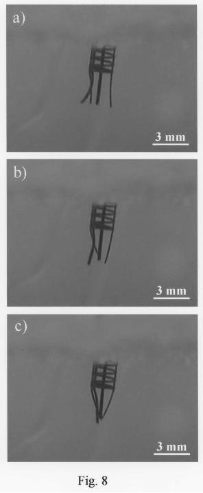
Fig. 8 shows photographs illustrating the movement of the micro-manipulator
achieved by changing the applied potential from a) -0.8 to b) 0 (at the time of the
change) and c) 0 V (1 min after the change) in 0.1 M NaDBS solution. At E = -0.8 V
(Fig. 8a), the 4 fingers of the microstructure point in the direction towards the outside of
the microstructure, while, just after switching to E = 0 V (Fig. 8b), the fingers bend
towards the inside, and the free ends of the fingers move to touch each other after
keeping the potential at E = 0 V (Fig. 8c) for 1 min. Reversing the potential change
from 0 to -0.8 V returned the fingers to the shape in Fig. 8a.
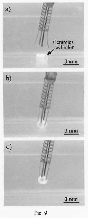
Fig. 9 shows photographs of the performance of the microstructure as a
micro-manipulator in 0.1 kmol m-3 NaDBS solution. In Fig. 9a, there is a 1.5 mm
diameter and 2.1 mm long mulite cylinder (6.5 mg) at the bottom of an electrolytic cell
under the micro-manipulator; the four fingers of the manipulator are open with the
16
potential at –0.8 V. In Fig. 9b the micro-manipulator has been moved downwards and
grips the cylinder; here the potential of the micro-manipulator is at E = 0 V. In Fig. 9c
the manipulator has been moved upwards, holding the cylinder.
In summary, 3D micro-actuators were fabricated by successive procedures of
aluminum anodizing, laser irradiation, and Au / acrylic resin / PPy electrodeposition,
and no distorted motion of the micro-manipulator fingers was observed.
Electrophoretic deposition of acrylic resin is considered to enable the no distorted
motion because of the uniform film thickness. The micro-manipulator in the present
investigation is difficult to fabricate by photolithography, and the technique described
here the feasibility in medicine, biotechnology, and microelectromechanical systems
(MEMS). In these applications, it is important to fabricate smaller actuators with
sub-millimeter size. The authors have already succeeded in micro-patterning with 5
µm line width on aluminum substrate [17]. The sub-millimeter size actuator can be
fabricated with smaller diameter aluminum tubes by the micro-patterning techniques
described above, although crack formation during anodizing may confine the thickness
of the PPy layer [10]. More precise and smaller actuators may be fabricated by

17
choosing the optimal fabrication condition.
4. CONCLUSIONS
The following conclusions may be drawn from the experiments reported above.
(1) Ribbon type and 3D micro-actuators with PPy / Au / acrylic acd resin three-layer
structures can be successfully fabricated by anodizing, laser irradiation, Au
electroplating, acrylic ace resin electrophoretic deposition, aluminum substrate and
oxide film dissolution, and PPy electro-polymerization.
(2) Ribbon type micro-manipulators can be activated by applying and changing
potentials, here from –0.8 to 0 V, repeatedly. The moving distance of the ribbon type
micro-actuator components depends strongly on the valency of the cations in solution:
monovalent cations (Li+, Na+) > divalent cations (Mg2+, Ca2+) > trivalent cations (Al3+,
little or no movement). The motion can be explained by a volume change due to the
doping and dedoping of hydrated cations into / from the PPy matrix.
(3) The three-dimensional micro-actuator can be used as a manipulator for gripping and
transferring small components.

18
References
1) T. F. Otero, H. Grande, and J. Rodriguez, Synth. Met. 83 (1996) 205.
2) T. F. Otero, I. Cantero, and H. Grande, Elechtrochim. Acta 44 (1999) 2053.
3) A. S. Hutchison, T. W. Lewis, S. E. Moulton, G. M. Spinks, and G. G. Wallace, Synth.
Met. 113 (2000) 121.
4) T. F. Otero and I. Boyano, J. Phys. Chem. B107 (2003) 6730.
5) J. W. Paquette, K. J. Kim, D. Kim, Sens. Actuators A118 (2005) 135.
6) J. H. Lee, J. H. Lee, J. D. Nam, H. Choi, K. Jung, J. W. Jeon, Y. K. Lee, K. J. Kim,
and Y. Tak, Sensors and Actuators A118 (2005) 98.
7) S. Maw, E. Smela, K. Yoshida, and R. B. Stein, Synth. Met. 155 (2005) 18.
8) G. Han and G. Shi, Sensors and Actuators B113 (2006) 259.
9) Y. Akiyama, T. Kikuchi, M. Ueda, M. Iida, M. Sakairi, and H. Takahashi,
Electrochim. Acta 51 (2006) 4834
10) T. Kikuchi, M. Sakairi, and H. Takahashi, J. Electrochem. Soc. 150 (2003) C567
11) T. Kikuchi, H. Takahashi, and T. Maruko, Electrochim. Acta. in press (Elsevier,

19
Science Direct)
12) S. Z. Chu, M. Sakairi, H. Takahashi, K. Shimamura, and Y. Abe, J. Electrochem.
Soc. 147 (2000) 2182
13) T. Kikuchi, S. Z. Chu, S. Jonishi, M. Sakairi, and H. Takahashi, Electrochim. Acta
47 (2001) 225
14) T. Kikuchi, M. Sakairi, H. Takahashi, Y. Abe, and N. Katayama, J. Electrochem. Soc.
148 (2001) C740
15) M. R. Gandhi, P. Murray, G. M. Spinks, and G. G. Wallace, Synth. Metals 73 (1995)
247
16) S. Skaarup, K. West, L. M. W. K. Gunaratne, K. P. Vidanapathirana, and M. A.
Careem, Solid State Ionics 136-137 (2000) 577
17) T. Kikuchi, M. Sakairi, H. Takahashi, Y. Abe, and N. Katayama, Surf. Coat. Technol.
169-170C (2003) 199
20
Captions
Table 1 Moving distance of ribbon type micro-actuator, d, the amount of anodic and
cathodic charge, Qa and Qc in cyclic voltammetry between –0.8 and 0.3 V, and specific
molar amounts of doped cations, Ms, in 0.1 kmol m-3 solutions of LiCl, NaCl, NaDBS,
MgCl2, CaCl2, and AlCl3.
Fig. 1 Steps in the fabrication of the PPy / Au / acrylic resin three-layer microstructure;
a) anodizing, b) laser irradiation, c) – d) Au / acrylic resin electrodeposition, e)
aluminum and oxide film dissolution, and f) PPy electro-polymerization.
Fig. 2 Cyclic voltammograms of the ribbon type actuator in 0.1 kmol m-3 NaDBS
solution at 5, 200, and 400 cycles.
Fig. 3 Cyclic voltammograms of the ribbon type actuator in 0.1 kmol m-3 solutions:
NaDBS, NaCl, and LiCl.
Fig. 4 Cyclic voltammograms of the ribbon type actuator in 0.1 kmol m-3 solutions of
MgCl2 and CaCl2.
Fig. 5 Cyclic voltammogram of ribbon type actuator in 0.1 M AlCl3 solution.
Fig. 6 Superimposed video images illustrating the bending motion of the ribbon type
21
micro-actuator in CaCl2 solution. Images obtained at a) E = 0 V and b) -0.8 V are
superimposed.
Fig. 7 Optical micrographs of a) Au micro-pattern on an aluminum tube after anodizing,
laser irradiation, and Au electrodeposition and b) three-layer micro-manipulator after
acrylic acid resin electrodeposition, aluminum and oxide film dissolution, and PPy
electrolytic polymerization.
Fig. 8 Video images illustrating the motion of the 3D micro-manipulator in 0.1 M
NaDBS solution at a) -0.8 V, b) just after changing to 0 V, and c) 1 min after changing to
0 V.
Fig. 9 Video images illustrating the motion of the 3D micro-manipulator gripping a
ceramics cylinder in 0.1 M NaDBS solution: a) opening the fingers at -0.8 V, b) holding
the cylinder at 0 V, and c) lifting the cylinder at 0 V.
22
Table 1
Ion species Moving distance, Anodic charge, Cathodic charge, Ratio of number of
d / mm Qa / C Qc / C doped cations, Ms
Li+ (Cl-) 4.74 677 1552 1.00
Na+ (Cl-) 5.39 883 1713 1.30
Na+ (DBS-) 4.86 933 1576 1.38
Mg2+ (Cl-)2 1.41 1007 1354 0.74
Ca2+ (Cl-)2 1.77 697 1304 0.51
Al3+ (Cl-)3 0 81 514 0.04