failure analysis report muffler diffuses geysers…/67531/metadc882446/m2/1/high... · raqpan -...
TRANSCRIPT

CORPO-ON
DCN# 8 0 - 2 12 - 003 - 11
FAILURE ANALYSIS REPORT GEOTHERMAL STEAM MUFFLER DIFFUSES
THE GEYSERS, CALIFORNIA
Prepared by: Ron McAlpin
P e t e r F. E l l i s , I1
Contract No. DE-ACO2-79ET27026
Prepared f o r : United S t a t e s Department of Energy
Chicago Operations and Regional Office Argonne, I l l i n o i s 60439
Apr i l 1980
8500 Shoal Creek Blvd. I P.O. Box 9948 I Austin, Texas 78766 /(512)454-4797

DISCLAIMER
This report was prepared as an account of work sponsored by an agency of the United States Government. Neither the United States Government nor any agency Thereof, nor any of their employees, makes any warranty, express or implied, or assumes any legal liability or responsibility for the accuracy, completeness, or usefulness of any information, apparatus, product, or process disclosed, or represents that its use would not infringe privately owned rights. Reference herein to any specific commercial product, process, or service by trade name, trademark, manufacturer, or otherwise does not necessarily constitute or imply its endorsement, recommendation, or favoring by the United States Government or any agency thereof. The views and opinions of authors expressed herein do not necessarily state or reflect those of the United States Government or any agency thereof.

DISCLAIMER Portions of this document may be illegible in electronic image products. Images are produced from the best available original document.

~
RADIAN - FAILURE ANALYSIS REPORT
GEOTHERMAL STEAM MUFFLER DIFFUSERS THE GEYSERS, CALIFORNIA
1.0 INTRODUCTION c
O n 29 January 1980, the Failure Analysis Laboratory at Radian Corporation received portions of the inner and outer diffusers from a geothermal steam discharge silencer-operated by Thermogenics , Incorporated at Unit #lS , The Geysers, Califor- nia, for determination of the cause of premature failure, This and several other T 304 stainless steel diffasers have failed with numerous cracks evident. This report considers the causes of failure of the inner and outer diffusers. A geothermal dis- charge silencer with steam input line is shown in Figure 1; Figure 2 shows several failed stainless steel diffusers.
This report is part of a continuing DOE effort to gain
The results of these analyses w i l l be incorporated insight into component materials employed in geothermal energy utilization. into the next issue of DOE'S Material Selection Guidelines for Geothermal Energy Systems.
The first commercial production of electricity from geothermal energy in the western hemisphere occurred in 1960 at
The first commercial production of electricity from geothermal energy in the western hemisphere occurred in 1960 at The Geysers, a vapor-dominated resource located in Sonoma and Lake counties, California. Steam from numerous geothermal wells is supplied to fifteen generating units with a combined capacity of over 900 MwCe).
a
.F
When a turbine is tripped off-line, steam is discharged through a silencer for noise abatement, as required by environmental
RAQPAN - regulations. walled cylindrical diffusers mounted horizontally in the base of a discharge tower (Figure 1) . lbm/hr of steam at 350°F is vented through the silencer.
The silencer at Unit 15 consists of two double-
During a trip, approximately 550,000 The dura-
" tion of a trip cycle varies from several hours to a full week.
c Unit #lS is the only unit at The Geysers to use a stain- less steel diffuser type muffler.
in a redwood box filled with lava rock. In the stack shown in Figure 1, there are two sets of diffusers, each with an inner and outer diffuser; both have failed. In approximately 20 cycles or actuations of the safety relief valves, one diffuser was completely destroyed and the other severely cracked. carbon steel diffusers of similar design were installed in August
A l l other units have success- perated with a carbon steel distribution header imbedded
After the failures,
1979. To date they have not failed.
2 . 0 GEOTHERMAL ENVIRONMENT
The exact composition of the geothermal steam supplied to Unit #15 has not been reported, and steam composition is ex- pected to vary as different wells are brought on-line. Table 1 presents the average steam composition of 61 production wells at The Geysers. The produced steam also contains small amounts of rock dust.
Chloride concentration in the steam was not reported. However, steam condensate, normally at six cycles of concentration, is used as cooling water at The Geysers. introduce chloride are used. for the recirculating concentrated steam condensate. From this data, mositure films formed as steam condenses are estimated to contain 0.16-1 6 ppm chloride.
0 No treatments which Table 1 gives the composition range
-

TABLE 1. THE GEYSERS AVERAGE FLUID CHEMISTRY
Circulating Steam2 Condensate
I Comp anent (PPm wt) (ppm except pH)
- 7.72 - 8 . 1 ' f Key Species: PH
c1 - <13 - 102 $04 - 802 - 258' HCO j - 1582 - 7532 co 3 - O 2 H2S 222-k 122 N H 3 194* 6g2 - 235' co2 3260* -

RAQIAN - /
At the beginning of a trip cycle, the diffuser is heated rapidly to 350"F, which is maintained until the end of the cycle. Steam expanding to atmospheric pressure at this temperature would be superheated. . A s the steam supplied to the diffuser is shut off, the unit cools and is wetted with condensate, which eventually evaporates to dryness. Thus the diffuser is exposed.to a wet-dry cyclic environment with temperatures ranging from 350" to ambient. This wet-dry cycling results in significant concentration of the chlorides present in the initial moisture film.
3 . 0 VISUAL OBSERVATIONS
r
The diffuser was fabricated from Type 304 stainless steel plate, with baffling holes mechanically punched; the plates were then cold-rolled and welded into place. was rolled from 3/8 inch plate with 3 / 4 inch punched holes; the outer diffuser was rolled from 3/16 inch plate with 3/16 inch
The inner diffuser
punched holes.
On both pieces, branching cracks that connected several of the punched holes were observed. in Figure 3 . The dark feature, indicated by an arrow, around the punched hole is a die mark from fabrication. section of approximately 6"x8" of each diffusion plate was re- ceived. several smaller cracks in the early propogation stage of growth.
4 . 0 EXPERIMENTAL PROCEDURE
A typical example is shown
One air-arc cut
Each contained two or three large primary cracks and
- Several fracture surfaces from each sample were removed
by saw-cbtting. microscope (SEM) for elemental surface chemistry analysis using energy-dispersive spectroscopy (EDS) , a fluorescent x-ray technique.
These specimens were placed in a scanning electron
4

Following this analysis, the fracture faces were electrolytically cleaned to remove oxides and scale, and studied using SEM fracto- raphy techniques.
- . Also, areas of crack initiation and primary crack growth were cut from the samples for metallographic analysis. were mounted, polished, and etched to reveal microstructure and crack propogation mode.
5 . 0 EXPERIMENTAL RESULTS
The samples
General surface chemistry analysis by EDS initially indicated trace amounts of sulfur and chlorine in addition to the 300 series stainless steel constituents (Fe-Cr-Ni). Figure 4 shows a crack that was later opened for further EDS analysis. The crack was opened by making a dry saw cut from an uncracked region to the tip of the primary crack. duced by EDS from a representative area of the crack surface is shown in Figure 5 .
The x-ray spectrum pro-
Major amounts of sulfur and chlorine were present.
The electron micrograph in Figure 6 displays an inter- granular facet on the heavily oxidized crack surface. line scan detecting chlorine concentration was performed across this area of localized intergranular attack. the micrograph, chloride (detected as elemental chlorine) concen- tration increased sharply on the facet.
An elemental
As demonstrated by
P From the metallographically polished and etched section, The micrograph
Figures
-
the microstructure and cracking mode was obtained.
is typical of an austenitic (300 series) stainless steel. 8 and 9 show.cracks in the initial stages of growth.
1 in Figure 7 demonstrates the microstructure of the material which
The cracks
5

RADIAN - have propogated i n a branching transgranular mode as shown in the higher magnification micrograph.
Following surface chemistry analysis, a l l fracture sur- 5 faces were electrolyt ical ly cleaned in a solution of Endox 214
for removal of oxides, and placed on the SEM for fractography. On a l l fracture faces studied, cracking in i t ia ted i n corrosion p i t s i n areas of high residual stresses l e f t by the die punching of baffling holes. roughly 3 / 4 of the surface. high-cycle fatigue and increased secondary cracking was vis ible in the f ina l stage. The electron micrograph in Figure 3.0 shows an area of f i na l fracture; secondary transgranular cracking and high-cycle fatigle/corrosion s t r ia t ions are evident. Localized intergranular attack was noted in various areas on the fracture
Cracking proceeded transgranularly across Evidence of vibrationally induced
surfaces.
6 .0 DISCUSS ION i
The fa i lure resulted from l o w energy transgranular crack- ing which in i t ia ted i n corrosion p i t s in areas of high residual s t ress . The cracks were found t o contain high residual concentra- tions of chloride. This fracture mode i n austenit ic s ta inless s t ee l , coupled with the chloride residue is indicative of chloride s t ress corrosion cracking (SCC) as the primary fa i lure mechanism. The f inal fracture occurred by high cycle corrosion/fatigue, as indicated by the s t r ia t ions and quasi-clevage impact markings on the fracture surface (Figure lo). A discussion of th i s fa i lure mode can be found i n reference 4 .
T304 and 316 stainless s tee l components have been used, successfully for other applications a t The Geysers. These compo- nents have endured the same basic chemical environment as the diffusers ; however, operating temperatures have been considerably
RADPAN COa
lower. It has been shown (reference 4 ) that chloride stress corrosion cracking requires temperqtures above 150°-185"F.
7.0 CONCLUS IONS
The primary failure mechanism for the T304
sion cracking. certain point, high cycle corrosion/fatigue proceeded to the final fracture.
. diffusers was chloride induced stress corro- Once SCC had progressed to a
Alteration of the environment to prevent SCC is not feasible.
The existing environment will also cause sul- fide stress cracking (SSC) in susceptible materials ; therefore, alternate materials must resist SSC as well as SCC.
The very large amplitude operational stresses make heat treatment to relieve residual fab- rication stress questionable for the preven- tion of SCC.
8.0 RE COMMENDATIONS
The following recommendations to promote longer and more reliable service for diffuser plates in the Unit #lS silencer
tive economics of the choices. t are based on engineering alternatives without regard to the rela-
Further study is required by ' Thermogenic to define the most cost-effective choice.
7

Any mention of a specific product, process, o r vendor i s not intended t o exclude other products, processes, o r vendors which may give comparable resul ts o r render comparable services.
In the event that the carbon s tee l diffusers presently in use f a i l by fatigue, the diffusers should be redesigned t o reduce cyclic stresses. This would be recornmended regardless of an a l - ternate material selection.
Carbon s tee l may be satisfactory f o r th i s application. However, i f serious p i t t ing occurs, fa i lure by corrosion-fatigue could occur.
. From cost considerations, l o w carbon s tee l with a protective coating should be con- sidered for t h i s application. The s tee l must have a hardness below HRC-22 i n order ~
t o r e s i s t SCC due t o the presence of hydro- gen sulfide. A suggested coating is P las t i te 4004-5 (product of Wisconsin Protective Coat- ings) w i t h a service l i m i t of 450°F.
Low alloy weathering s tee ls such as Cor-Ten A are intended for wet-dry service and may give better corrosion resistance than carbon s tee l . \Hardness must be less than HRC-22 t o
' res is t SSC.
Because 400 series stainless s tee ls are sus- ceptible t o SSC, they can not be recommended for th i s use.
8
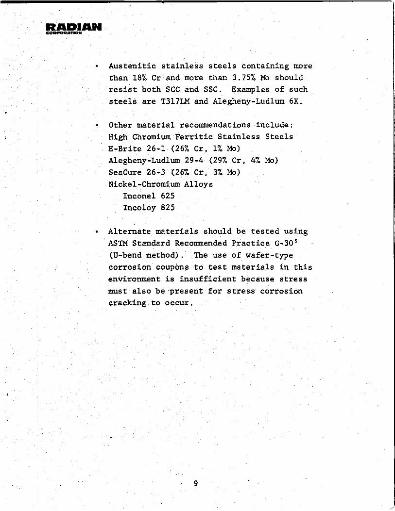
Austenitic stainless steels containing more than 18% Cr and more than 3.75% Mo should resist both SCC and SSC. Examples of such steels are T317LM and Alegheny-Ludlum 6X.
*
Other material recommendations include: L High Chromium Ferritic Stainless Steels
E-Brite 26-1 (26% Cr, 1% Mo) Alegheny-Ludlum 29-4 (29% Cr, 4% Mo) SeaCure 26-3 (26% Cr, 3% Mo) Nickel-Chromium Alloys
Inconel 625 Incoloy 825
Alternate materials should be tested using ASTM Standard Recommended Practice G-30’ - (U-bend method). corrosion coupons to test materials in this environment is insufficient because stress must also be present for stress corrosion cracking to occur,
The use of wafer-type
9.0 REFERENCES
. 1. Ivy, S. T. and F r i e d r i c h , S . J . , "Corrosion Fa t igue of Type 403 and 422 Stainless Steel i n Geothermal Steam," presented a t NACE Corrosion/79, A t l a n t a , GA, 12-16 March 1979.
c 2. Ham, W. C . , "Materials and Corrosion, Geysers Geothermal
Power P l a n t , It presented a t NACE Western Regional Conference, San Franc isco , CA, 3-5 October 1972.
3 . Dodd, F. J . , Johnson, A. E., and Ham, W. C . , "Materials and Corrosion Tes t ing a t The Geysers Geothermal Power P l a n t , " p re sen ted a t t h e Second United Nations Symposium on t h e Development and Use of Geothermal Resources, San Franc isco , CA, 20-28 May 1975.
DeBerry, D. W:, E l l i s P. F. , and Thomas, C . C . , Materials S e l e c t i o n Guidelines f o r Geothermal Power Systems, F i r s t E d i t i o n , DOE Contract No. EG-774-04-3904, NTIS Pub. Code ALO-3904-1, Radian Corporat ion, Austin, Texas, September 1978.
5 . American Soc ie ty f o r Testing and Materials, "Standard Recom- mended P r a c t i c e f o r Making and Using U-bend Stress Corrosion T e s t Specimens," ASTM Standard 6-30-72 i n 1978 Annual Book of ASTM Standards , P a r t 10 , Ph i l ade lph ia , ASTM, 1978, pp. 758-766.
10

RADIAN W 7
c
Figure 1. Geothermal discharge silencer.

. :
Figure 2. Failed geothermal diffuser (diameter = 27 inches).

i
Figure 3 . Crack i n inner diffuser. Dark feature to right i s a die mark.
Magnification: 4X *
i
-D lie Ma rk
Figure 4 . Crack to be opened for surface chemistry Magnification : 200X
analysis.


f
Scan Line
Chlorine Concentrat (RELATIVE)
:i
'Scan Line
Figure 6 . Chlorine co centration on crack surface. Magniftcation: 4 2ooX
I
/
I Chlorine Concentrati (RELATIVE)
I
t

Figure 7. Microstructure of diffuser. Magnification: 200X
Etchant: Marble’s Reagent
. Figure 8. Branching crack in diffuser.
Etchant : Marble ’ s Reagent Magnification: lOOX

i
Figure 9. Crack in diffuser; note high degree of transgranular cracking.
Magnification: 800X Etchant: Marble's Reanent
b Figure 10. Final fracture on diffuser. Magnification: 450X