fairfield fagus limited - gov.uk · pdf filethe osprey subsea field is located 6 km north west...
TRANSCRIPT
Fairfield Fagus Limited
Osprey Pipelines and Structures Decommissioning Programmes (DP2) (Non-Derogation) Final Version FFL-DUN-OSP-HSE-01-PLN-00001


II Document Control
Approvals
Name
Prepared by Jonathan Bird
Reviewed by James Clarkson
Approved by Peter Lee
Revision Control
Revision No Reference
Rl Issued for Comment
Al BEIS Pre-Consultation Draft
A2 BEIS Pre-Consultation Draft
A3 Fairfield review of Pre-Consultation Draft
A4 BEIS Consu ltation Draft
AS BEIS Consultation Draft
A6 Consultation Draft
A7 Post Consultation Draft
AB Post Consu ltation Draft
A9 Fina l
Distribution List
Name Company
Internal Distribution Fairfield
Osprey Pipelines and Structures Decommissioning Programmes (DP2)
Issue A9
Signature Date
~~ 8 0€C 201'°1-
.-.JC....L ~ /12./1-=1-
p\.. s l,z,l11
Changes I Comments Issue Date
1st draft 27 Jun 2016
Rev Rl FEL comments included. Issued for BEIS 18 Ju l 2016
Rev Al FEL / BEIS comments included. Issued to BEIS for 28 Sep 2016 review.
Comparative assessment and environmental impact
22 Mar 2017 assessment I environmental statement output added
CA and EIA input 31Mar2017
BEIS comments included 2 Jun 2017
BEIS comments included 16 Jun 2017
BEIS comments included 3 Nov 2017
Stakeholder comments 17 Nov 2017
included
Partner Letters of Support 08 Dec 2017
No. of Copies for Formal Consultation
FEL DCC
Offshore Decommissioning Department for Business, Energy and One
Unit Industrial Strategy (BEIS)
Steven Alexander Scottish Fishermen's Federation (SFF) (also Three
Raymond Hall representing NFFO and NIFPO)
John Wrottesley Global Marine Systems One
Document Number: FFL-DUN-OSP-HSE-01-PLN-00001 Page 1 of63

Osprey Pipelines and Structures Decommissioning Programmes (DP2)
Issue A9
Document Number: FFL-DUN-OSP-HSE-01-PLN-00001 Page 2 of 63
Page intentionally left blank

Osprey Pipelines and Structures Decommissioning Programmes (DP2)
Issue A9
Document Number: FFL-DUN-OSP-HSE-01-PLN-00001 Page 3 of 63
Contents
INST P/L
1 EXECUTIVE SUMMARY 11 1.1 Combined Decommissioning Programmes 11 1.2 Requirement for Decommissioning Programmes 11 1.3 Introduction 12 1.4 Overview of Installations / Pipelines Being Decommissioned 12 1.5 Summary of Proposed Decommissioning Programmes 14 1.6 Field Location Including Field Layout and Adjacent Facilities 17 1.7 Industrial Implications 21 2 DESCRIPTION OF ITEMS TO BE DECOMMISSIONED 23 2.1 Installations: Surface Facilities 23 2.2 Installations: Subsea including Stabilisation Features 23 2.3 Pipelines Including Stabilisation Features 27 2.4 Wells 39 2.5 Drill Cuttings 39 2.6 Inventory Estimates 39 3 REMOVAL AND DISPOSAL METHODS 42 3.1 Topsides 42 3.2 Jacket 42 3.3 Subsea Installations and Stabilisation Features 43 3.4 Pipelines 43 3.5 Pipeline Stabilisation Features 48 3.6 Wells 49 3.7 Drill Cuttings 49 3.8 Waste Streams 50 4 ENVIRONMENTAL IMPACT ASSESSMENT 52 4.1 Environmental Sensitivities (Summary) 52 4.2 Potential Environmental Impacts and their Management 53 5 INTERESTED PARTY CONSULTATIONS 55 5.1 Consultations Summary 55 6 PROGRAMME MANAGEMENT 56 6.1 Project Management and Verification 56 6.2 Post-Decommissioning Debris Clearance and Verification 56 6.3 Schedule 56 6.4 Costs 57 6.5 Close Out 57 6.6 Post-decommissioning Monitoring and Evaluation 57 7 SUPPORTING DOCUMENTS 59 8 PARTNER LETTER OF SUPPORT 60 9 APPENDIX 1 – STATUTORY CONSULTEE CORRESPONDENCE 61 10 APPENDIX 2 – PUBLIC NOTICES 63
√ √
√
√
√
√
√
√
√
√
√
√
√
√
√
√
√ √
√
√
√ √
√
√
√
√
√
√ √ √ √
√ √
√
√
√
√
√
√
√
√
√
√
√
√
√
√ √
√
√
√ √
√
√
√
√
√
√ √ √ √

Osprey Pipelines and Structures Decommissioning Programmes (DP2)
Issue A9
Document Number: FFL-DUN-OSP-HSE-01-PLN-00001 Page 4 of 63
Page intentionally left blank

Osprey Pipelines and Structures Decommissioning Programmes (DP2)
Issue A9
Document Number: FFL-DUN-OSP-HSE-01-PLN-00001 Page 5 of 63
Abbreviations
Abbreviation Explanation BEIS Department for Business, Energy and Industrial Strategy (formerly DECC) CA Comparative Assessment CGBS Concrete Gravity Based Structure Comms Communications COP Cessation of Production DCC Document Control Centre DECC Department of Energy and Climate Change (now called BEIS) DP Decommissioning Programme(s) DSV Diving Support Vessel EIA Environmental Impact Assessment ES Environmental Statement FBL Fairfield Betula Limited FEL Fairfield Energy Limited FFL Fairfield Fagus Limited FWMS Fairfield Waste Management Strategy GMS Global Marine Systems IM Interim Manifold INST Installation IPR Interim Pipeline Regime IVHJ Isolation Valve Hydraulic Jumper JIP Joint Industry Project JOA Joint Operating Agreement LSA Low Specific Activity (related to NORM) MCDA Multi Criteria Decision Analysis MER Maximising Economic Recovery MODU Mobile Drilling Unit MoM Minute of Meeting N/A Non Applicable NFFO National Federation of Fishermen's Organisations NIFPO Northern Ireland Fish Producers' Organisation Limited NORM Naturally Occurring Radioactive Material (related to LSA) OGA Oil & Gas Authority OGUK Oil & Gas United Kingdom OOS Out of Service OPRED Offshore Petroleum Regulator for Environment and Decommissioning OSPAR Oslo Paris Convention P&A Plug and Abandon PBLM Production Block Linear Manifold PETS Portal Environmental Tracking System PGB Production Guidebase PJB Production Junction Box PL Pipeline PMT Project Management Team PON Petroleum Operations Notice Prod Production
Osprey Pipelines and Structures Decommissioning Programmes (DP2)
Issue A9
Document Number: FFL-DUN-OSP-HSE-01-PLN-00001 Page 6 of 63
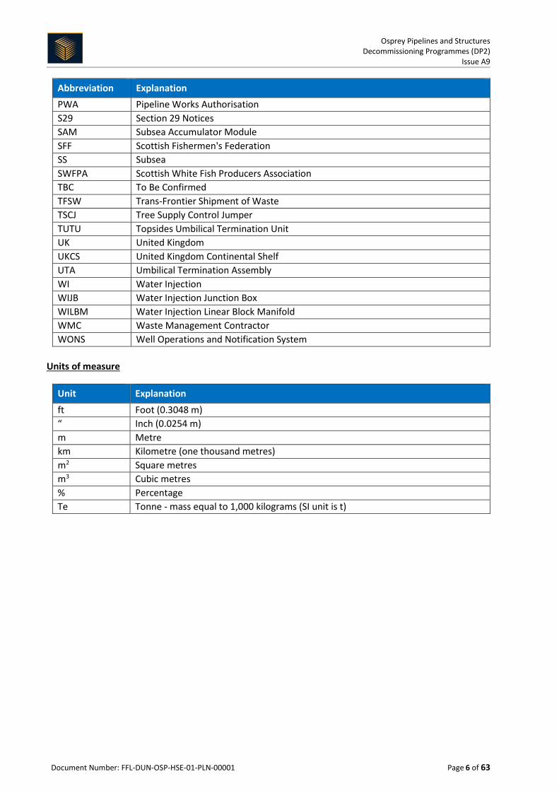
Abbreviation Explanation PWA Pipeline Works Authorisation S29 Section 29 Notices SAM Subsea Accumulator Module SFF Scottish Fishermen's Federation SS Subsea SWFPA Scottish White Fish Producers Association TBC To Be Confirmed TFSW Trans-Frontier Shipment of Waste TSCJ Tree Supply Control Jumper TUTU Topsides Umbilical Termination Unit UK United Kingdom UKCS United Kingdom Continental Shelf UTA Umbilical Termination Assembly WI Water Injection WIJB Water Injection Junction Box WILBM Water Injection Linear Block Manifold WMC Waste Management Contractor WONS Well Operations and Notification System
Units of measure
Unit Explanation ft Foot (0.3048 m) “ Inch (0.0254 m) m Metre km Kilometre (one thousand metres) m2 Square metres m3 Cubic metres % Percentage Te Tonne - mass equal to 1,000 kilograms (SI unit is t)

Osprey Pipelines and Structures Decommissioning Programmes (DP2)
Issue A9
Document Number: FFL-DUN-OSP-HSE-01-PLN-00001 Page 7 of 63
Figures and Tables
Figure 1-1: Field Location in UKCS ................................................................................................................ 17 Figure 1-2: Greater Dunlin Area Configuration Map .................................................................................... 18 Figure 1-3: Greater Dunlin Area Field Layout ............................................................................................... 19 Figure 1-4: Osprey Field Layout .................................................................................................................... 20 Figure 2-1: Pie Chart of Estimated Inventories (Installations) ..................................................................... 40 Figure 2-2: Pie Chart of Estimated Inventories (Pipelines)........................................................................... 41 Figure 6-1: Gantt Chart of Project Schedule ................................................................................................ 57
Table 1-1: Installations Being Decommissioned ........................................................................................... 12 Table 1-2: Installations S29 Notice Holders Details...................................................................................... 13 Table 1-3: Pipelines Being Decommissioned ................................................................................................ 13 Table 1-4: Pipelines S29 Notice Holders Details ........................................................................................... 13 Table 1-5: Pipelines S29 Notice Holders Details ........................................................................................... 14 Table 1-6: Summary of Decommissioning Programmes .............................................................................. 14 Table 1-7: Adjacent Facilities ........................................................................................................................ 21 Table 2-1: Surface Facilities Information ...................................................................................................... 23 Table 2-2: Subsea Installations and Stabilisation Features .......................................................................... 23 Table 2-3: Pipeline / Flowline / Umbilical Information ................................................................................ 27 Table 2-4: Subsea Pipeline Stabilisation Features ........................................................................................ 38 Table 2-5: Well Information ......................................................................................................................... 39 Table 2-6: Drill Cuttings Pile Information ..................................................................................................... 39 Table 2-7: Inventory of material associated with Osprey pipelines and structures removal ...................... 40 Table 3-1: Cleaning of Topsides for Removal ............................................................................................... 42 Table 3-2: Topsides Removal Methods ........................................................................................................ 42 Table 3-3: Jacket Decommissioning Methods .............................................................................................. 42 Table 3-4: Subsea Installations and Stabilisation Features .......................................................................... 43 Table 3-5: Pipeline or Pipeline Groups Decommissioning Options .............................................................. 44 Table 3-6: Outcomes of Comparative Assessment ...................................................................................... 46 Table 3-7: Pipeline Stabilisation Features .................................................................................................... 48 Table 3-8: Well Plug and Abandonment ...................................................................................................... 49 Table 3-9: Drill Cuttings Decommissioning Options ..................................................................................... 49 Table 3-10: Waste Stream Management Methods ...................................................................................... 50 Table 3-11: Inventory Disposition ................................................................................................................ 50 Table 3-12: Waste Disposal Aspirations ....................................................................................................... 51 Table 4-1: Environmental Sensitivities ......................................................................................................... 52 Table 4-2: Environmental Impact Management .......................................................................................... 54 Table 5-1: Summary of Stakeholder Comments .......................................................................................... 55 Table 6-1: Provisional Decommissioning Programmes costs ....................................................................... 57 Table 7-1: Supporting Documents ................................................................................................................ 59

Osprey Pipelines and Structures Decommissioning Programmes (DP2)
Issue A9
Document Number: FFL-DUN-OSP-HSE-01-PLN-00001 Page 8 of 63
Page intentionally left blank

Osprey Pipelines and Structures Decommissioning Programmes (DP2)
Issue A9
Document Number: FFL-DUN-OSP-HSE-01-PLN-00001 Page 9 of 63
Appendices
Appendix Description Page
1 Statutory Consultee Correspondence 62
2 Public Notices 64

Osprey Pipelines and Structures Decommissioning Programmes (DP2)
Issue A9
Document Number: FFL-DUN-OSP-HSE-01-PLN-00001 Page 10 of 63
Page intentionally left blank
Osprey Pipelines and Structures Decommissioning Programmes (DP2)
Issue A9
Document Number: FFL-DUN-OSP-HSE-01-PLN-00001 Page 11 of 63
1 EXECUTIVE SUMMARY
1.1 Combined Decommissioning Programmes This document contains the Decommissioning Programmes (DPs) for the Osprey field subsea installations and pipelines that apply to the following Section 29 (S29) Notices:
1. Osprey block and subsea facilities (issued August 2008) 2. Osprey pipelines (issued August 2008) 3. Osprey pipelines (issued March 2016).
Note that the Dunlin Alpha installation is subject to a separate Decommissioning Programme FBL-DUN-DUNA-HSE-01-PLN-00001. The Greater Dunlin Area integrated Decommissioning Programmes are described in the Greater Dunlin Area DP Bridging Document FBL-DUN-DAOM-HSE-01-PLN-00001. The latest revision of the decommissioning documents can be found on the Fairfield website:
http://www.fairfield-energy.com
1.2 Requirement for Decommissioning Programmes MCX Osprey (UK) Ltd. holds a 100% interest in the Osprey licence and is therefore the Owner of all Osprey infrastructure. Fairfield Fagus Ltd. (FFL) is the appointed licence operator under a Joint Operating Agreement (JOA) in relation to all Osprey licences with Fairfield Betula Ltd. (FBL) as the 'Lead Operator' under a JOA in relation to all of Dunlin, Osprey and Merlin fields.
FFL and MCX Osprey (UK) Ltd. are included as S29 notice holders of all Osprey infrastructure.
This project forms part of, and is integrated with, the overall Greater Dunlin Area decommissioning programme. The schedule outlined in this document spans seven years from Cessation of Production (COP) to completion, with execution activities beginning post approval of these DPs. In conjunction with public, stakeholder and regulatory consultation, the decommissioning programmes are submitted in compliance with national and international regulations and DECC guidelines.
1.2.1 Installations
In accordance with the Petroleum Act 1998, the S29 Notice holders of the Osprey installations / field (see Table 1-2) are applying to the Department for Business, Energy and Industrial Strategy (BEIS, formerly DECC) to obtain approval for decommissioning the installations detailed in section 2.1 and 2.2 of this programme (see also section 8 Partner Letter of Support).
1.2.2 Pipelines
In accordance with the Petroleum Act 1998, the S29 Notice holders of the Osprey pipelines (see Table 1-4) are applying to BEIS to obtain approval for decommissioning the pipelines detailed in section 2.3 of this programme (see also section 8 Partner Letter of Support).

Osprey Pipelines and Structures Decommissioning Programmes (DP2)
Issue A9
Document Number: FFL-DUN-OSP-HSE-01-PLN-00001 Page 12 of 63
1.3 Introduction These decommissioning programmes have been prepared to support decommissioning of the Osprey Field, which is part of a wider suite of decommissioning programmes for the Greater Dunlin Area.
The Greater Dunlin Area consists of the Dunlin, Dunlin South West, Osprey and Merlin Fields, located in the Shetland Basin of the northern North Sea. The Dunlin Alpha platform served as the production facility for the Greater Dunlin Area and is located in block 211/23a, approximately 137 km north east of Scotland and 11 km from the UK / Norwegian median line, in a water depth of 151 m.
The Dunlin Alpha platform was installed in 1977 and two subsea tiebacks, Osprey and Merlin, were developed in 1991 and 1997 respectively. During its lifetime, over 522 million barrels of oil have been produced from the Greater Dunlin Area.
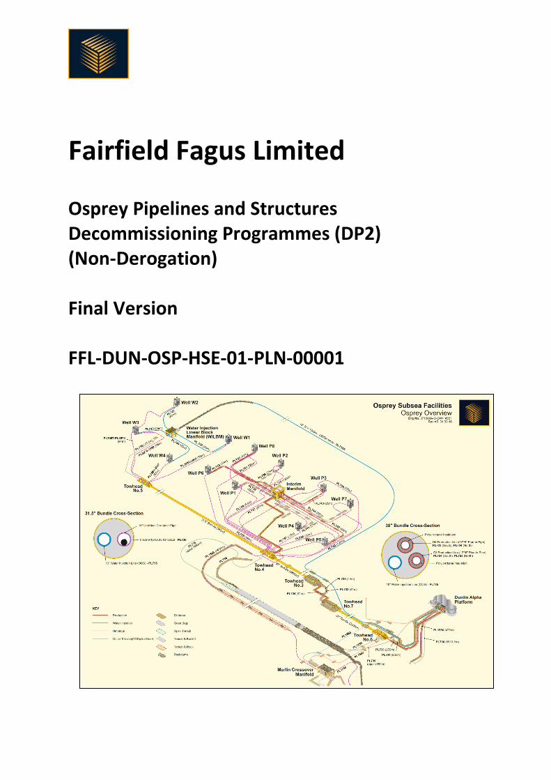
The Osprey subsea field is located 6 km north west of Dunlin Alpha in blocks 211/23a and 211/18a in a water depth of 159 m, and consists of two subsea templates, complete with eight production wells and four water injection wells respectively. Oil was produced via a subsea production manifold, and transported through two 8” production lines contained within a 38” bundle carrier pipe to Dunlin Alpha platform.
The original 10” water injection pipeline contained within the 38” carrier pipe suffered a loss of integrity in July 2002, after which water injection was supplied by a 10” flexible pipeline via a central Water Injection Linear Block Manifold (WILBM) to the four satellite injection wells.
Termination of Production from the Greater Dunlin Area was announced in May 2015, following achievement of Maximising Economic Recovery (MER) from these oilfields. Termination of Production was agreed with the OGA on 9th July 2015, with Cessation of Production (COP) confirmed by letter dated 15th January 2016, to have occurred on 15th June 2015.
The methodologies required for the decommissioning of infrastructure and pipelines associated with the Osprey field are in compliance with BEIS and Oil & Gas UK (OGUK) guidelines and are subject to full public, stakeholder and regulatory consultation. These are further supported through Comparative Assessment (CA) of removal options and by an Environmental Impact Assessment (EIA) of the preferred option.
1.4 Overview of Installations / Pipelines Being Decommissioned
1.4.1 Installations
Table 1-1: Installations Being Decommissioned
Field: Osprey
Production Type (Oil / Gas / Condensate) Oil
Water Depth (m) 159 UKCS block 211/23a and 211/18a
Surface Installations
Number Type Topsides Weight (Te) Jacket Weight (Te)
N/A N/A N/A N/A

Osprey Pipelines and Structures Decommissioning Programmes (DP2)
Issue A9
Document Number: FFL-DUN-OSP-HSE-01-PLN-00001 Page 13 of 63
Table 1-1: Installations Being Decommissioned
Subsea Installations Number of Wells
Number Type Platform Subsea
8 Manifolds (x2), Protection Frames (x4), Dummy Wellheads (x2)
N/A 12
Drill Cuttings Pile Distance to median Distance from nearest UK coastline
Number of Piles Total Estimated volume (m3) (Dunlin Alpha ref. point) (Dunlin Alpha ref. point)
2 3052 11 km 137 km
Table 1-2: Installations S29 Notice Holders Details
S29 Notice Holders Registration Number Equity Interest (%) If zero show 0%
Esso Exploration and Production UK Limited 00207426 0%
Fairfield Energy Limited 05562373 0%
Fairfield Fagus Limited 05461823 0%
MCX Osprey (UK) Limited 06451720 100%
Mitsubishi Corporation BR005199 0%
Shell UK Limited 00140141 0%
1.4.2 Pipelines
Table 1-3: Pipelines Being Decommissioned
Number of Pipelines Seventy-Two (72) uniquely numbered lines
(See section 2.3)
Table 1-4: Pipelines S29 Notice Holders Details
S29 Notice Holders Registration Number Equity Interest (%) If zero show 0%
Esso Exploration and Production UK Limited 00207426 0%
Fairfield Fagus Limited 05461823 0%
MCX Osprey (UK) Limited 06451720 100%
Mitsubishi Corporation BR005199 0%
Shell UK Limited 00140141 0%
The above table lists the S29 Notice holders for the following pipelines: PL733 to PL761, PL735A, PL1545.1 to .18 and PLU4263.

Osprey Pipelines and Structures Decommissioning Programmes (DP2)
Issue A9
Document Number: FFL-DUN-OSP-HSE-01-PLN-00001 Page 14 of 63
Table 1-5: Pipelines S29 Notice Holders Details
S29 Notice Holders Registration Number Equity Interest (%) If zero show 0%
Fairfield Fagus Limited 05461823 0%
MCX Osprey (UK) Limited 06451720 100%
Mitsubishi Corporation BR005199 0%
The above table lists the S29 Notice holders for the following pipelines: PL2837, PL3001JWP1 to PL3001JWP7, PL3001JWP4A, PL3960 to PL3987, PL4337, PLU4336 and PLU4335
1.5 Summary of Proposed Decommissioning Programmes
Table 1-6: Summary of Decommissioning Programmes Selected Option Reason for Selection Proposed Decommissioning
Solution 1. Topsides
N/A N/A N/A
2. Jacket / Floating Facility (FPSO, etc.)
N/A N/A N/A
3. Subsea Installations
Xmas trees will be removed using a MODU. The wellheads may be removed by the MODU or at a later stage using a DSV.
Removal of all seabed structures to leave a clear seabed.
There are no wellhead protection frames or over trawlable structures in place on the wells. Wellheads and associated completion materials will be removed to (minus) -3 m.
Interim Manifold (IM) Removal of all seabed structures to leave a clear seabed.
Full removal.
WILBM Removal of all seabed structures to leave a clear seabed.
Full removal.
4. Pipelines, Flowlines and Umbilicals1
Group 1: pipeline and umbilical components
Leaves clear seabed and meets regulations.
Full removal.
Group 2a: deposits Leaves clear seabed and meets regulations.
Full removal.
Group 2b: structures Leaves clear seabed and meets regulations.
Full removal.
1 FBL-DUN-OSP-SSP-01-RPT-00003 - Osprey Subsea Assets, Burial Status.

Osprey Pipelines and Structures Decommissioning Programmes (DP2)
Issue A9
Document Number: FFL-DUN-OSP-HSE-01-PLN-00001 Page 15 of 63
Table 1-6: Summary of Decommissioning Programmes Selected Option Reason for Selection Proposed Decommissioning
Solution Group 3: bundles Comparatively assessed as preferred
option. The bundles are stable, posing no hazard to marine users. Minimal seabed disturbance, lower energy usage, reduced risk to personnel engaged in the activity.
Partial Removal.
Group 4: surface laid flexible jumpers
Leaves clear seabed and meets regulations.
Full removal.
Group 5: flexible and umbilical risers
Comparatively assessed as preferred option. The risers are contained within the Dunlin Alpha concrete gravity based structure.
Partial Removal.
Group 6: surface laid rigid spools
Leaves clear seabed and meets regulations.
Full removal.
Group 7: surface laid flexible pipelines
Leaves clear seabed and meets regulations.
Full removal.
Group 8: trenched and rock covered umbilicals
Comparatively assessed as preferred option. The pipelines and umbilicals are sufficiently buried and stable, posing no hazard to marine users. Minimal seabed disturbance, lower energy usage, reduced risk to personnel engaged in the activity.
Partial Removal.
Group 9: surface laid umbilicals
Leaves clear seabed and meets regulations.
Full removal.
Group 10: surface laid, rock covered pipelines
Leaves clear seabed and meets regulations.
Full removal.
5. Wells
Abandoned in accordance with OGUK Guidelines for the Abandonment of Wells, issue 5, July 2015
Meets regulatory requirements. A PON5 will be in submitted through the OGA Well Operations and Notification System (WONS) and Chemical Permit and Marine Licences will be submitted through the Portal Environmental to support the work to be carried out.

Osprey Pipelines and Structures Decommissioning Programmes (DP2)
Issue A9
Document Number: FFL-DUN-OSP-HSE-01-PLN-00001 Page 16 of 63
6. Drill Cuttings
Leave in place to degrade naturally.
Cuttings coverage is small, thin and widely dispersed and falls below both of OSPAR 2006/5 thresholds.
Left undisturbed on seabed.
Criteria: Osprey Production Wells Cuttings: Osprey Water Injection Wells Cuttings:
Area (m2) 5,834 3,092
Volume (m3) 2,130 922
Average depth of cover (m) 0.60 0.59
Max depth of cover (m) 1.47 2.40
7. Interdependencies
None

Osprey Pipelines and Structures Decommissioning Programmes (DP2)
Issue A9
Document Number: FFL-DUN-OSP-HSE-01-PLN-00001 Page 17 of 63
1.6 Field Location Including Field Layout and Adjacent Facilities
Figure 1-1: Field Location in UKCS

Osprey Pipelines and Structures Decommissioning Programmes (DP2)
Issue A9
Document Number: FFL-DUN-OSP-HSE-01-PLN-00001 Page 18 of 63
Figure 1-2: Greater Dunlin Area Configuration Map

Osprey Pipelines and Structures Decommissioning Programmes (DP2)
Issue A9
Document Number: FFL-DUN-OSP-HSE-01-PLN-00001 Page 19 of 63
Figure 1-3: Greater Dunlin Area Field Layout

Osprey Pipelines and Structures Decommissioning Programmes (DP2)
Issue A9
Document Number: FFL-DUN-OSP-HSE-01-PLN-00001 Page 20 of 63
Figure 1-4: Osprey Field Layout
Osprey Pipelines and Structures Decommissioning Programmes (DP2)
Issue A9
Document Number: FFL-DUN-OSP-HSE-01-PLN-00001 Page 21 of 63
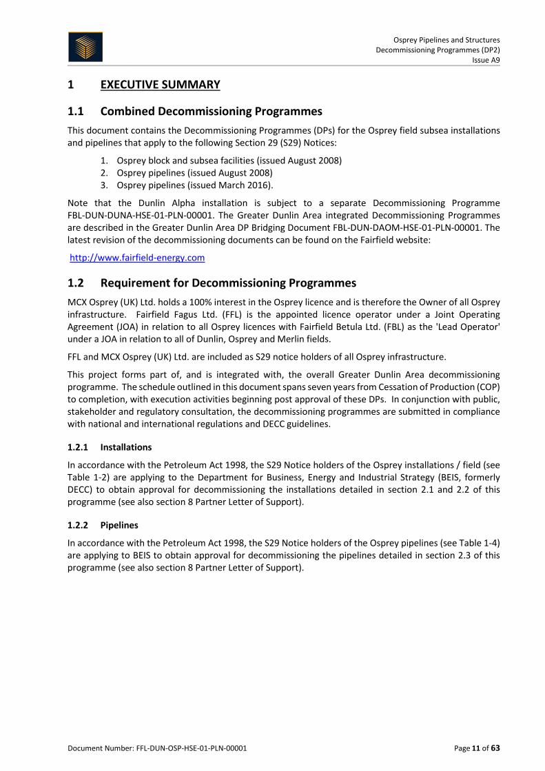
Table 1-7: Adjacent Facilities
Operator Name Type Distance / Direction Information Status
FBL Dunlin Alpha
Platform Osprey - Dunlin Alpha 6.11 km (3.8 miles) south east
Host to Osprey. COP, provides up and over service to Thistle, exports to Cormorant Alpha.
FFL Merlin Subsea Osprey - Merlin 5.24 km (3.3 miles) south west
Merlin ties into the Osprey system.
COP, out of use.
EnQuest Thistle Platform Dunlin Alpha - Thistle 9.87 km (6.17 miles) north north west
Thistle exports to Dunlin Alpha for up and over services, plus supplied fuel gas for Dunlin Alpha water injection primary movers.
Operational.
TAQA Cormorant Alpha
Platform Dunlin Alpha - Cormorant Alpha 34.12 km (21.33 miles) south west
Dunlin exports to Cormorant Alpha.
Operational.
Shell Brent Charlie
Platform Dunlin Alpha - Brent Charlie 20.99 km (13.12 miles) south east
Provided electrical power and comms to Dunlin Alpha.
DPI electrical supply is out of use, DPI comms are in use, Brent Charlie is Operational.
CNR Murchison Platform Dunlin Alpha - Murchison 15.89 km (9.93 miles) north east
Being decommissioned. Disconnected from Dunlin Alpha.
Out of use, being decommissioned.
Impacts of Decommissioning Proposals
The Osprey field will be decommissioned along with Merlin, Dunlin Alpha and associated infrastructure.
1.7 Industrial Implications The Greater Dunlin Area Decommissioning Project will be managed by FBL in Aberdeen. There will be a number of specialist contract services required for the execution of the Greater Dunlin Area

Osprey Pipelines and Structures Decommissioning Programmes (DP2)
Issue A9
Document Number: FFL-DUN-OSP-HSE-01-PLN-00001 Page 22 of 63
Decommissioning Project, including but not limited to; engineering studies, subsea infrastructure decommissioning, topsides preparation for removal, topsides removal, topsides recycling / disposal.
In planning, preparing and executing the decommissioning of the Greater Dunlin Area, FBL will ensure that all contracts are raised and administered in a consistent and effective manner and that they:
• Adhere to the ethical and safety standards of the company • Meet the requirements of legislation and all other relevant external organisations • Are processed and awarded with tight and proper controls which will meet all stakeholder
requirements • Are focussed on the maximisation of safe, efficient and cost effective decommissioning
service delivery.
FBL will also engage with the supply chain to identify effective technological solutions that are environmentally acceptable and safe.
Osprey Pipelines and Structures Decommissioning Programmes (DP2)
Issue A9
Document Number: FFL-DUN-OSP-HSE-01-PLN-00001 Page 23 of 63
2 DESCRIPTION OF ITEMS TO BE DECOMMISSIONED
2.1 Installations: Surface Facilities
Table 2-1: Surface Facilities Information
N/A
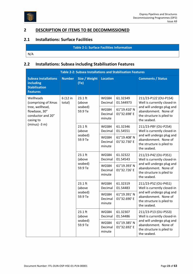
2.2 Installations: Subsea including Stabilisation Features
Table 2-2: Subsea Installations and Stabilisation Features
Subsea installations including Stabilisation Features
Number Size / Weight (Te)
Location Comments / Status
Wellheads (comprising of Xmas tree, wellhead, flowbase, 30” conductor and 20” casing to (minus) -3 m)
6 (12 in total)
23.1 ft (above seabed) 59.9 Te
WGS84 Decimal
61.32349 01.544973
211/23-P12Z (OU-P1S4) Well is currently closed-in and will undergo plug and abandonment. None of the structure is piled to the seabed.
WGS84 Decimal minute
61°19.410' N 01°32.698' E
23.1 ft (above seabed) 59.9 Te
WGS84 Decimal
61.32346 01.54551
211/23-P8Y (OU-P2S4) Well is currently closed-in and will undergo plug and abandonment. None of the structure is piled to the seabed.
WGS84 Decimal minute
61°19.408' N 01°32.730' E
23.1 ft (above seabed) 59.9 Te
WGS84 Decimal
61.32322 01.54543
211/23-P4Z (OU-P3S1) Well is currently closed-in and will undergo plug and abandonment. None of the structure is piled to the seabed.
WGS84 Decimal minute
61°19.393' N 01°32.726' E
23.1 ft (above seabed) 59.9 Te
WGS84 Decimal
61.32319 01.54483
211/23-P5Z (OU-P4S1) Well is currently closed-in and will undergo plug and abandonment. None of the structure is piled to the seabed.
WGS84 Decimal minute
61°19.391' N 01°32.690' E
23.1 ft (above seabed) 59.9 Te
WGS84 Decimal
61.32307 01.54486
211/23-P13 (OU-P5S3) Well is currently closed-in and will undergo plug and abandonment. None of the structure is piled to the seabed.
WGS84 Decimal minute
61°19.385' N 01°32.692' E

Osprey Pipelines and Structures Decommissioning Programmes (DP2)
Issue A9
Document Number: FFL-DUN-OSP-HSE-01-PLN-00001 Page 24 of 63
23.1 ft (above seabed) 59.9 Te
WGS84 Decimal
61.32364 01.54494
211/23-P6 (OU-P6) Well is currently closed-in and will undergo plug and abandonment. None of the structure is piled to the seabed.
WGS84 Decimal minute
61°19.419' N 01°32.696' E
Wellheads (comprising of Xmas tree, wellhead, flowbase, 30” conductor and 20” casing to (minus) -3 m)
6 (12 in total)
23.1 ft (above seabed) 59.9 Te
WGS84 Decimal
61.32311 01.54542
211/23-P7 (OU-P7) Well is currently closed-in and will undergo plug and abandonment. None of the structure is piled to the seabed.
WGS84 Decimal minute
61°19.387' N 01°32.726' E
18.2 ft (above Seabed) 49.5 Te
WGS84 Decimal
61.32358 01.54548
211/23-P11 (OU-P8) Well is currently closed-in and will undergo plug and abandonment. None of the structure is piled to the seabed.
WGS84 Decimal minute
61°19.415' N 01°32.729' E
23.1 ft (above seabed) 59.9 Te
WGS84 Decimal
61.32631 01.54565
211/23-W1Z (OU-W1S1) Well is currently closed-in and will undergo plug and abandonment. None of the structure is piled to the seabed.
WGS84 Decimal Minute
61°19.579' N 01°32.741' E
23.1 ft (above seabed) 59.9 Te
WGS84 Decimal
61.32679 01.54567
211/23-W2Y (OU-W2S2) Well is currently closed-in and will undergo plug and abandonment. None of the structure is piled to the seabed.
WGS84 Decimal Minute
61°19.608' N 01°32.741' E
23.1 ft (above seabed) 59.9 Te
WGS84 Decimal
61.32671 01.54508
211/23-W3 (OU-W3) Well is currently closed-in and will undergo plug and abandonment. None of the structure is piled to the seabed.
WGS84 Decimal Minute
61°19.603' N 01°32.705' E
23.1 ft (above seabed) 59.9 Te
WGS84 Decimal
61.32646 01.54510
211/23-W4Z (OU-W4S1) Well is currently closed-in and will undergo plug and abandonment. None of the structure is piled to the seabed.
WGS84 Decimal Minute
61°19.588' N 01°32.706' E

Osprey Pipelines and Structures Decommissioning Programmes (DP2)
Issue A9
Document Number: FFL-DUN-OSP-HSE-01-PLN-00001 Page 25 of 63
Manifolds 2 5 m x 4 m x 3 m 18.1 Te
WGS84 Decimal
61.32660 01.54537
WIBLM.
WGS84 Decimal minute
61°19.596' N 01°32.722' E
4 m x 3.5 m x 3 m 24.6 Te
WGS84 Decimal
61.32334 01.54520
Osprey Production IM.
WGS84 Decimal minute
61°19.401' N 01°32.712' E
PLBM (manifold)
1 7.2 m x 4.1 m x 4.1 m 65Te
N/A The PLBM was recovered in 2013, stripped, cleaned and stored.
Dummy wellheads 2 2.6 m x 2.6 m x 2.9 m 6.5 Te (PGB) 30” x 15.6 m 11.4 Te (conductor)
WGS84 Decimal
61.32660 01.54537
WIBLM. Dummy wellhead complete with permanent guidebase and 30” conductor.
WGS84 Decimal minute
61°19.596' N 01°32.722' E
2.6 m x 2.6 m x 2.9 m 6.5 Te (PGB) 30” x 15.6 m 11.4 Te (conductor)
WGS84 Decimal
61.32334 01.54520
Osprey Production IM. Dummy wellhead complete with permanent guidebase and 30” conductor.
WGS84 Decimal minute
61°19.401' N 01°32.712' E
Templates N/A N/A N/A N/A N/A
Protection Structures
4 5 m x 4 m x 8 m 25.0 Te
WGS84 Decimal
61.27391 01.59507
Osprey Water Injection Protection Structure. The structure is not piled. WGS84
Decimal minute
61°16.435' N 01°35.704' E
5 m x 8 m x 8 m 29.5 Te
WGS84 Decimal
61.26746 01.59511
Osprey Production Protection Structure. The structure is not piled. WGS84
Decimal minute
61°16.048' N 01°35.707' E
15 m x 7 m x 1.6 m 13.2 Te
WGS84 Decimal
61.29972 01.56556
Towhead 3 Protection Structure. The structure is not piled. WGS84
Decimal minute
61°17.983' N 01°33.934' E
15 m x 7 m x 1.6 m 11.6 Te
WGS84 Decimal
61.29934 01.56563
Towhead 7 Protection Structure. The structure is not piled. WGS84
Decimal minute
61°17.960' N 01°33.938' E

Osprey Pipelines and Structures Decommissioning Programmes (DP2)
Issue A9
Document Number: FFL-DUN-OSP-HSE-01-PLN-00001 Page 26 of 63
Concrete mattresses N/A N/A N/A N/A
Grout bags N/A N/A N/A N/A
Formwork N/A N/A N/A N/A
Frond Mats N/A N/A N/A N/A
Rock Cover N/A N/A N/A N/A
Other N/A N/A N/A N/A

Osprey Pipelines and Structures Decommissioning Programmes (DP2)
Issue A9
Document Number: FFL-DUN-OSP-HSE-01-PLN-00001 Page 27 of 63
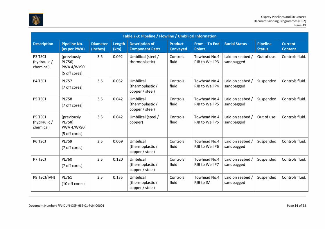
2.3 Pipelines Including Stabilisation Features Water Injection and production pipelines are listed in the direction of flow.
Table 2-3: Pipeline / Flowline / Umbilical Information
Description Pipeline No. (as per PWA)
Diameter (inches)
Length (km)
Description of Component Parts
Product Conveyed
From – To End Points
Burial Status Pipeline Status
Current Content
Osprey water injection riser
PL735A
8 0.234 Flexible (polymer/steel)
Water; chemicals
Dunlin Alpha to Wye Piece
Laid on seabed / mattressed / partially within J-tube
Out of use Flushed with inhibited seawater.
Osprey water injection pipeline
PL735A 8 & 10 0.0035 Rigid wye piece (steel)
Water; chemicals
PL735A Riser to PL735A Pipeline
Laid on seabed / mattressed
Out of use Flushed with inhibited seawater.
Osprey water injection pipeline
PL735A
10 6.600 (2x 3.300)
Flexible (polymer/steel)
Water; chemicals
Wye Piece to WILBM
Laid on seabed / partial rock cover
Out of use Flushed with inhibited seawater.
W1 flexible jumper
PL746 6 0.025 Flexible (polymer / steel)
Water; chemicals
WILBM to W1 Laid on seabed Out of use Flushed with inhibited seawater.
W2 flexible jumper
PL747 6 0.025 Flexible (polymer / steel)
Water; chemicals
WILBM to W2 Laid on seabed Out of use Flushed with inhibited seawater.
W3 flexible jumper
PL748 6 0.025 Flexible (polymer / steel)
Water; chemicals
WILBM to W3 Laid on seabed Out of use Flushed with inhibited seawater.

Osprey Pipelines and Structures Decommissioning Programmes (DP2)
Issue A9
Document Number: FFL-DUN-OSP-HSE-01-PLN-00001 Page 28 of 63
Table 2-3: Pipeline / Flowline / Umbilical Information
Description Pipeline No. (as per PWA)
Diameter (inches)
Length (km)
Description of Component Parts
Product Conveyed
From – To End Points
Burial Status Pipeline Status
Current Content
W4 flexible jumper
PL749 6 0.025 Flexible (polymer / steel)
Water; chemicals
WILBM to W4 Laid on seabed Out of use Flushed with inhibited seawater.
Water Injection Line – South Bundle
PL735
10 3.239 Rigid pipeline (steel) - contained within 38” carrier pipe
Water; chemicals
Towhead No.6 to Towhead No.7
Within bundle - Laid on seabed
Out of use Flushed with inhibited seawater.
Osprey water injection jumper
PL735
8 0.055 Flexible (polymer / steel)
Water; chemicals
Towhead No.7 to Towhead No.3
Laid on seabed / mattressed
Out of use Flushed with inhibited seawater.
Water Injection Line – North Bundle
PL735
10 3.237 Rigid pipeline (steel) - contained within 38” and 31” carrier pipe
Water; chemicals
Towhead No.3 to Towhead No.5
Within bundle - Laid on seabed
Out of use Flushed with inhibited seawater.
Osprey water injection jumper
PL735
8 0.055 Flexible (polymer / steel)
Water; chemicals
Towhead No.5 to WILBM
Laid on seabed / mattressed
Out of use Flushed with inhibited seawater.
P1 production jumper
PL738 6 0.025 Flexible (polymer / steel)
Production fluid
Well P1 to Osprey IM
Laid on seabed / mattressed
Out of use Flushed / methanol.
P2 production jumper
PL739 6 0.025 Flexible (polymer / steel)
Production fluid
Well P2 to Osprey IM
Laid on seabed / mattressed
Out of use Flushed / methanol.
P3 production jumper
PL740 6 0.025 Flexible (polymer / steel)
Production fluid
Well P3 to Osprey IM
Laid on seabed / mattressed
Out of use Flushed / methanol.

Osprey Pipelines and Structures Decommissioning Programmes (DP2)
Issue A9
Document Number: FFL-DUN-OSP-HSE-01-PLN-00001 Page 29 of 63
Table 2-3: Pipeline / Flowline / Umbilical Information
Description Pipeline No. (as per PWA)
Diameter (inches)
Length (km)
Description of Component Parts
Product Conveyed
From – To End Points
Burial Status Pipeline Status
Current Content
P4 production jumper
PL741 6 0.025 Flexible (polymer / steel)
Production fluid
Well P4 to Osprey IM
Laid on seabed / mattressed
Out of use Flushed / methanol.
P5 production jumper
PL742 6 0.040 Flexible (polymer / steel)
Production fluid
Well P5 to Osprey IM
Laid on seabed / mattressed
Out of use Flushed with inhibited seawater.
P6 production jumper
PL743 6 0.040 Flexible (polymer / steel)
Production fluid
Well P6 to Osprey IM
Laid on seabed / mattressed
Out of use Flushed / methanol.
P7 production jumper
PL744 6 0.040 Flexible (polymer / steel)
Production fluid
Well P7 to Osprey IM
Laid on seabed / mattressed
Out of use Flushed / seawater.
P8 production jumper
PL745 6 0.040 Flexible (polymer / steel)
Production fluid
Well P8 to Osprey Interim Manifold
Laid on seabed / mattressed
Out of use Flushed / methanol.
Osprey production pipeline tie-in
PL734
8 0.046 Rigid spools (steel / FBE / SPU coating)
Production fluid
Osprey IM to Towhead No.4
Mattressed / supported on grout piers
Out of use Flushed with inhibited seawater.

Osprey Pipelines and Structures Decommissioning Programmes (DP2)
Issue A9
Document Number: FFL-DUN-OSP-HSE-01-PLN-00001 Page 30 of 63
Table 2-3: Pipeline / Flowline / Umbilical Information
Description Pipeline No. (as per PWA)
Diameter (inches)
Length (km)
Description of Component Parts
Product Conveyed
From – To End Points
Burial Status Pipeline Status
Current Content
Production Line – North Bundle
PL733 8 2.871 Rigid Pipeline (Steel) - contained within 12” carrier pipe, located within 38” bundle carrier
Production fluid
Towhead No.4 to Towhead No.3
Within bundle - Laid on seabed
Out of use Flushed with inhibited seawater.
Production Line – North Bundle
PL734 8 2.871 Rigid Pipeline (Steel) - contained within 12” carrier pipe, located within 38” bundle carrier
Production fluid
Towhead No.4 to Towhead No.3
Within bundle - Laid on seabed
Out of use Flushed with inhibited seawater.
Osprey production pipeline tie-in
PL734
8 0.050 Rigid spools (steel / FBE / SPU coating)
Production fluid
Towhead No.3 to Towhead No.7
Laid on seabed / mattressed
Out of use Flushed with inhibited seawater.
Osprey production pipeline tie-in
PL733 8 0.055 Flexible (polymer / steel)
Production fluid
Towhead No.3 to Towhead No.7
Laid on seabed / mattressed
Out of use Flushed with inhibited seawater.
Production Line – South Bundle
PL733 8 3.239 Rigid Pipeline (Steel) - contained within 12” carrier pipe, located within 38” bundle carrier
Production Fluid
Towhead No.7 to Towhead No.6
Within bundle - Laid on seabed
Out of use Flushed with inhibited seawater.

Osprey Pipelines and Structures Decommissioning Programmes (DP2)
Issue A9
Document Number: FFL-DUN-OSP-HSE-01-PLN-00001 Page 31 of 63
Table 2-3: Pipeline / Flowline / Umbilical Information
Description Pipeline No. (as per PWA)
Diameter (inches)
Length (km)
Description of Component Parts
Product Conveyed
From – To End Points
Burial Status Pipeline Status
Current Content
Production Line – South Bundle
PL734 8 3.241 Rigid Pipeline (Steel) - contained within 12” carrier pipe, located within 38” bundle carrier
Production Fluid
Towhead No.7 to Towhead No.6
Within bundle - Laid on seabed
Out of use Flushed with inhibited seawater.
Osprey production riser
PL734
8 0.255 Flexible (polymer / steel)
Production fluids
Towhead No.6 to Dunlin Alpha ESDV
Laid on seabed / mattressed / partially within J-tube
Out of use Flushed with inhibited seawater.
Osprey production topside pipework2
PL734
8 0.090 Rigid Pipeline (Steel) Production fluids
Dunlin Alpha ESDV to Pig Receiver
N/A Out of use Flushed with inhibited seawater.
Osprey production riser
PL733 8 0.255
Flexible (polymer / steel)
Production fluids
Towhead No.6 to Dunlin Alpha ESDV
Laid on seabed / mattressed / partially within J-tube
Out of use Flushed with inhibited seawater.
Osprey production topside pipework3
PL733 8 0.090 Rigid Pipeline (Steel) Production fluids
Dunlin Alpha ESDV to Pig Launcher
N/A Out of use Flushed with inhibited seawater.
2 PL734 topside pipework shall be removed as part of the Dunlin Alpha topsides removal and will be included in the Dunlin Alpha Decommissioning Programme. 3 PL733 topside pipework shall be removed as part of the Dunlin Alpha topsides removal and will be included in the Dunlin Alpha Decommissioning Programme.

Osprey Pipelines and Structures Decommissioning Programmes (DP2)
Issue A9
Document Number: FFL-DUN-OSP-HSE-01-PLN-00001 Page 32 of 63
Table 2-3: Pipeline / Flowline / Umbilical Information
Description Pipeline No. (as per PWA)
Diameter (inches)
Length (km)
Description of Component Parts
Product Conveyed
From – To End Points
Burial Status Pipeline Status
Current Content
Osprey umbilical riser - repair
PL736 (7 off cores)
3 0.650 Umbilical (polymer / steel / copper / thermoplastic)
Controls fluid
Dunlin Alpha TUTU to 5” Osprey umbilical weak link
Laid on seabed / rock cover / mattressed / partially within J-tube
Out of use Seawater.
Osprey umbilical
PL736 (15 off cores)
5 6.700 Umbilical (polymer / steel / copper / thermoplastic) Umbilical Termination Assembly (UTA) (steel)
Controls fluid
Dunlin Alpha TUTU to Towhead No.4
Trenched and buried over 6.073 km / partial rock cover
Out of use Controls fluid.
Osprey umbilical - north repair
PL736 (15 off cores)
5 0.891 Umbilical (polymer / steel / copper / thermoplastic)
Controls fluid
PL736 north splice to Towhead No.4
Laid on seabed / trenched
Out of use Controls fluid.

Osprey Pipelines and Structures Decommissioning Programmes (DP2)
Issue A9
Document Number: FFL-DUN-OSP-HSE-01-PLN-00001 Page 33 of 63
Table 2-3: Pipeline / Flowline / Umbilical Information
Description Pipeline No. (as per PWA)
Diameter (inches)
Length (km)
Description of Component Parts
Product Conveyed
From – To End Points
Burial Status Pipeline Status
Current Content
Osprey umbilical – North Bundle
PLU4263 (15 off cores)
5 0.370 Umbilical (polymer / steel / copper / thermoplastic) - contained within 10” carrier pipe, located within 31.5” bundle carrier
Controls fluid
Towhead No.4 PJB to Towhead No.5 WIJB
Within Bundle - Laid on Seabed
Suspended Potable water as from Q1 2018.
Osprey control umbilical
PL1545 (18 off cores)
4 6.400 Umbilical (polymer / steel / copper) UTA (steel)
Controls fluid
Merlin crossover manifold to UTA (Towhead No.4)
Trenched over 6.121 km / spot rock cover
Suspended Potable water as from Q1 2018.
P1 TSCJ PL754 (7 off cores)
3.5 0.054 Umbilical (thermoplastic / copper / steel)
Controls fluid
Towhead No.4 PJB to Well P1
Laid on seabed / sandbagged
Suspended Controls fluid.
P2 TSCJ PL755 (7 off cores)
3.5 0.120 Umbilical (thermoplastic / copper / steel)
Controls fluid
Towhead No.4 PJB to Well P2
Laid on seabed / sandbagged
Suspended Controls fluid.
P3 TSCJ PL756 (7 off cores)
3.5 0.092 Umbilical (thermoplastic / steel)
Controls fluid
Towhead No.4 PJB to Well P3
Laid on seabed / sandbagged
Suspended Controls fluid.
Osprey Pipelines and Structures Decommissioning Programmes (DP2)
Issue A9
Document Number: FFL-DUN-OSP-HSE-01-PLN-00001 Page 34 of 63
Table 2-3: Pipeline / Flowline / Umbilical Information
Description Pipeline No. (as per PWA)
Diameter (inches)
Length (km)
Description of Component Parts
Product Conveyed
From – To End Points
Burial Status Pipeline Status
Current Content
P3 TSCJ (hydraulic / chemical)
(previously PL756) PWA 4/W/90 (5 off cores)
3.5 0.092 Umbilical (steel / thermoplastic)
Controls fluid
Towhead No.4 PJB to Well P3
Laid on seabed / sandbagged
Out of use Controls fluid.
P4 TSCJ PL757 (7 off cores)
3.5 0.032 Umbilical (thermoplastic / copper / steel)
Controls fluid
Towhead No.4 PJB to Well P4
Laid on seabed / sandbagged
Suspended Controls fluid.
P5 TSCJ PL758 (7 off cores)
3.5 0.042 Umbilical (thermoplastic / copper / steel)
Controls fluid
Towhead No.4 PJB to Well P5
Laid on seabed / sandbagged
Suspended Controls fluid.
P5 TSCJ (hydraulic / chemical)
(previously PL758) PWA 4/W/90 (5 off cores)
3.5 0.042 Umbilical (steel / copper)
Controls fluid
Towhead No.4 PJB to Well P5
Laid on seabed / sandbagged
Out of use Controls fluid.
P6 TSCJ PL759 (7 off cores)
3.5 0.069 Umbilical (thermoplastic / copper / steel)
Controls fluid
Towhead No.4 PJB to Well P6
Laid on seabed / sandbagged
Suspended Controls fluid.
P7 TSCJ PL760 (7 off cores)
3.5 0.120 Umbilical (thermoplastic / copper / steel)
Controls fluid
Towhead No.4 PJB to Well P7
Laid on seabed / sandbagged
Suspended Controls fluid.
P8 TSCJ/IVHJ PL761 (10 off cores)
3.5 0.135 Umbilical (thermoplastic / copper / steel)
Controls fluid
Towhead No.4 PJB to IM
Laid on seabed / sandbagged
Suspended Controls fluid.

Osprey Pipelines and Structures Decommissioning Programmes (DP2)
Issue A9
Document Number: FFL-DUN-OSP-HSE-01-PLN-00001 Page 35 of 63
Table 2-3: Pipeline / Flowline / Umbilical Information
Description Pipeline No. (as per PWA)
Diameter (inches)
Length (km)
Description of Component Parts
Product Conveyed
From – To End Points
Burial Status Pipeline Status
Current Content
IM MVHJ PL737 (4 off cores)
3 0.050 Umbilical (thermoplastic / steel)
Controls fluid
Towhead No.4 PJB to IM
Laid on seabed / sandbagged / mattressed
Suspended Controls fluid.
P1 IVHJ PL3001JWP1 (3 off cores)
3
0.024 Umbilical (thermoplastic / steel)
controls fluid
Well P1 to IM Laid on seabed / mattressed
Suspended Controls fluid.
P2 IVHJ PL3001JWP2 (3 off cores)
3
0.024 Umbilical (thermoplastic / steel)
Controls fluid
Well P2 to IM Laid on seabed / mattressed
Suspended Controls fluid.
P3 IVHJ PL3001JWP3 (3 off cores)
3
0.033 Umbilical (thermoplastic / steel)
Controls fluid
Well P3 to IM Laid on seabed / mattressed
Suspended Controls fluid.
P3 IVHJ (out of service)
PLU4335 (3 off cores)
3
0.024 Umbilical (thermoplastic / steel)
Controls fluid
Well P3 to IM Laid on seabed / sandbagged
Not in service
Controls fluid.
P4 IVHJ PL3001JWP4 (3 off cores)
3
0.033 Umbilical (thermoplastic / steel)
Controls fluid
Well P4 to IM Laid on seabed / mattressed
Suspended Controls fluid.
P4 IVHJ (out of service)
PL3001JWP4A (3 off cores)
3
0.033 Umbilical (thermoplastic / steel)
Controls fluid
Disconnected - laid on seabed
Laid on seabed / sandbagged
Out of use Controls fluid.

Osprey Pipelines and Structures Decommissioning Programmes (DP2)
Issue A9
Document Number: FFL-DUN-OSP-HSE-01-PLN-00001 Page 36 of 63
Table 2-3: Pipeline / Flowline / Umbilical Information
Description Pipeline No. (as per PWA)
Diameter (inches)
Length (km)
Description of Component Parts
Product Conveyed
From – To End Points
Burial Status Pipeline Status
Current Content
P5 IVHJ PL3001JWP5 (3 off cores)
3
0.047 Umbilical (thermoplastic / steel)
Controls fluid
Well P5 to IM Laid on seabed / mattressed
Suspended Controls fluid.
P5 IVHJ (out of service)
PLU4336 (3 off cores)
3
0.024 Umbilical (thermoplastic / steel)
Controls fluid
Well P5 to IM Laid on seabed / sandbagged
Suspended Controls fluid.
P6 IVHJ PL3001JWP6 (3 off cores)
3
0.047 Umbilical (thermoplastic / steel)
Controls fluid
Well P6 to IM Laid on seabed / mattressed
Suspended Controls fluid.
P7 IVHJ PL3001JWP7 (3 off cores)
3
0.024 Umbilical (thermoplastic / steel)
Controls fluid
Well P7 to IM Laid on seabed / mattressed
Suspended Controls fluid.
W1 TSCJ PL3960 - PL3966 (7 off cores)
3.5 0.080 Umbilical (thermoplastic / copper / steel)
Controls fluid
Towhead No.5 WIJB to W1
Laid on seabed / sandbagged
Suspended Controls fluid.
W2 TSCJ PL3967 - PL3973 (7 off cores)
3.5 0.094 Umbilical (thermoplastic / copper / steel)
Controls fluid
Towhead No.5 WIJB to W2
Laid on seabed / sandbagged
Suspended Controls fluid.
W3 TSCJ PL3974 - PL3980 (7 off cores)
3.5 0.066 Umbilical (thermoplastic / copper / steel)
Controls fluid
Towhead No.5 WIJB to W3
Laid on seabed / sandbagged
Suspended Controls fluid.
Osprey Pipelines and Structures Decommissioning Programmes (DP2)
Issue A9
Document Number: FFL-DUN-OSP-HSE-01-PLN-00001 Page 37 of 63
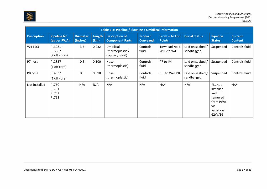
Table 2-3: Pipeline / Flowline / Umbilical Information
Description Pipeline No. (as per PWA)
Diameter (inches)
Length (km)
Description of Component Parts
Product Conveyed
From – To End Points
Burial Status Pipeline Status
Current Content
W4 TSCJ PL3981 - PL3987 (7 off cores)
3.5 0.032 Umbilical (thermoplastic / copper / steel)
Controls fluid
Towhead No.5 WIJB to W4
Laid on seabed / sandbagged
Suspended Controls fluid.
P7 hose PL2837 (1 off core)
0.5 0.100 Hose (thermoplastic)
Controls fluid
P7 to IM Laid on seabed / sandbagged
Suspended Controls fluid.
P8 hose PL4337 (1 off core)
0.5 0.090 Hose (thermoplastic)
Controls fluid
PJB to Well P8 Laid on seabed / sandbagged
Suspended Controls fluid.
Not installed PL750 PL751 PL752 PL753
N/A N/A N/A N/A N/A N/A PLs not installed and removed from PWA via variation 62/V/16
N/A

Osprey Pipelines and Structures Decommissioning Programmes (DP2)
Issue A9
Document Number: FFL-DUN-OSP-HSE-01-PLN-00001 Page 38 of 63
Table 2-4: Subsea Pipeline Stabilisation Features
Stabilisation Feature Total Number
Weight (Te) Location Status
Concrete mattresses (5 m x 2 m x 0.15 m)
240 864 (3.6 Te each)
PL733 (x19); PL734 (x38); PL735 (x8); PL735A (x20); PL736 (x29); PL738 – PL745 (x75); North Bundle (x2); South Bundle (x11); PL1545 (x38)
Exposed
Concrete mattresses (6 m x 2 m x 0.15 m)
8 34.6 (4.32 Te each)
PL1545 (x8) Exposed
Concrete mattresses (6 m x 3 m x 0.15 m)
12 81.0 (6.75 Te each)
PL734 (x7); PL735A (x1); North Bundle (x4);
Exposed
Concrete mattresses (6 m x 3 m x 0.3 m)
6 49.8 (8.3 Te each)
PL735A (x6) Exposed
Grout bags 280 7.0 (25 kg each)
PL733 (x140); PL734 (x140) Exposed
Sand bags 5,295 132.4 (25 kg each)
PL734 (x4,035); PL735 (x540); PL738 – PL745 (x720)
Exposed
Formwork N/A N/A N/A N/A
Frond mats N/A N/A N/A N/A
Rock cover N/A 18,926 Te in total
PL736 - OOS (3,820 Te); PL735A (4,211 Te); PL1545 (10,895 Te)
PL736 is trenched and buried on its own – rock is above mean seabed level. PL735A is surface laid on its own – rock is above mean seabed level. PL1545 is within its own trench – rock is below mean seabed level.
Other N/A N/A N/A N/A
Osprey Pipelines and Structures Decommissioning Programmes (DP2)
Issue A9
Document Number: FFL-DUN-OSP-HSE-01-PLN-00001 Page 39 of 66
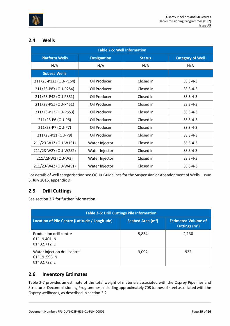
2.4 Wells
Table 2-5: Well Information
Platform Wells Designation Status Category of Well
N/A N/A N/A N/A
Subsea Wells
211/23-P12Z (OU-P1S4) Oil Producer Closed in SS 3-4-3
211/23-P8Y (OU-P2S4) Oil Producer Closed in SS 3-4-3
211/23-P4Z (OU-P3S1) Oil Producer Closed in SS 3-4-3
211/23-P5Z (OU-P4S1) Oil Producer Closed in SS 3-4-3
211/23-P13 (OU-P5S3) Oil Producer Closed in SS 3-4-3
211/23-P6 (OU-P6) Oil Producer Closed in SS 3-4-3
211/23-P7 (OU-P7) Oil Producer Closed in SS 3-4-3
211/23-P11 (OU-P8) Oil Producer Closed in SS 3-4-3
211/23-W1Z (OU-W1S1) Water Injector Closed in SS 3-4-3
211/23-W2Y (OU-W2S2) Water Injector Closed in SS 3-4-3
211/23-W3 (OU-W3) Water Injector Closed in SS 3-4-3
211/23-W4Z (OU-W4S1) Water Injector Closed in SS 3-4-3
For details of well categorisation see OGUK Guidelines for the Suspension or Abandonment of Wells. Issue 5, July 2015, appendix D.
2.5 Drill Cuttings See section 3.7 for further information.
Table 2-6: Drill Cuttings Pile Information
Location of Pile Centre (Latitude / Longitude) Seabed Area (m2) Estimated Volume of Cuttings (m3)
Production drill centre 61° 19.401' N 01° 32.712' E
5,834 2,130
Water injection drill centre 61° 19 .596' N 01° 32.722' E
3,092 922
2.6 Inventory Estimates Table 2-7 provides an estimate of the total weight of materials associated with the Osprey Pipelines and Structures Decommissioning Programmes, including approximately 708 tonnes of steel associated with the Osprey wellheads, as described in section 2.2.

Osprey Pipelines and Structures Decommissioning Programmes (DP2)
Issue A9
Document Number: FFL-DUN-OSP-HSE-01-PLN-00001 Page 40 of 66
A further breakdown of the inventory estimates for Subsea Installations and Subsea Pipelines is provided in Figure 2-1 and Figure 2-2 respectively.
All wells will be abandoned in accordance with OGUK Guidelines for the Abandonment of Wells, Issue 5, July 2015. A PON5 will be submitted through the OGA WONS and Chemical Permits and Marine Licences will be submitted via the BEIS Oil Portal (PETS) system to support the work to be carried out. Xmas trees will be removed using a MODU. The wellheads may also be removed by the MODU or at a later stage using a DSV.
Table 2-7: Inventory of material associated with Osprey pipelines and structures removal
Item Description Mass (t)
Metals Ferrous (steel - all grades) 6,529
Non-ferrous (copper; aluminium; zinc; indium) 76.4
Concrete Aggregates (mattresses; grout bags; sand bags) 1,202
Plastic Rubbers; polymers 288
Hazardous Residual fluids (hydrocarbons; chemicals; control fluid) 18.42
NORM scale 10.1
Other Fibre optics -
Total (tonnes) 8,124
Figure 2-1: Pie Chart of Estimated Inventories (Installations)
Figure 2-1 includes 65 tonnes of steel associated with the Osprey PLBM which was recovered for in 2013.
Please refer to sections 2.1 and 7.1 of the Osprey Subsea Decommissioning Environmental Statement for further details.
96%
4%Plastics <1%
Non-ferrous metals <1% NORM/Hazardous <1%
Other <1%
Estimated Inventory - Installations
Ferrous metals
Concrete
Plastics
Non-ferrous metals
NORM/Hazardous
Other
Total mass = 931 Te (excluding rock cover)

Osprey Pipelines and Structures Decommissioning Programmes (DP2)
Issue A9
Document Number: FFL-DUN-OSP-HSE-01-PLN-00001 Page 41 of 66
Figure 2-2: Pie Chart of Estimated Inventories (Pipelines)
Please refer to sections 2.1 and 7.1 of the Osprey Subsea Decommissioning Environmental Statement for further details.
78%
16%
4%
Non-ferrous metals 1%NORM/Hazardous <1%
Other <1%
Estimated Inventory - Pipelines
Ferrous metals
Concrete
Plastics
Non-ferrous metals
NORM/Hazardous
Other
Total mass = 7,193 Te(excluding rock cover)

Osprey Pipelines and Structures Decommissioning Programmes (DP2)
Issue A9
Document Number: FFL-DUN-OSP-HSE-01-PLN-00001 Page 42 of 66
3 REMOVAL AND DISPOSAL METHODS
In line with the waste hierarchy principles, reuse of pipelines and subsea installations (or parts thereof) was first in the order of preferred decommissioning options for assessment. The reuse of Osprey bundles (PL733 and PL734) complete with integrated towheads was not considered an option due to the technological challenges associated with re-floating and relocating the bundles. The reuse of Osprey pipelines within the bundles was not considered an option as they are past their service life and contain known defects that prohibit continued use. Reuse of manifolds was also dismissed due to the age and bespoke design of this type of equipment.
Recovered infrastructure will be returned to shore and transferred to a suitably licensed decommissioning facility. It is expected that the manifolds, flowlines, spool pieces and control jumpers would be cleaned before being largely recycled.
Concrete mattresses, grout bags, and sand bags will be cleaned of marine growth onshore if required, and either reused, recovered as aggregate for infrastructure projects, or sent to landfill.
An appropriately licensed disposal yard has not yet been selected. However, the selection process will ensure that the chosen facility is able to demonstrate a proven disposal track record and waste stream management throughout the deconstruction process, as well as the ability to deliver innovative reuse /recycling options. Locations of potential disposal yards may require the consideration of Trans-Frontier Shipment of Waste (TFSW), including hazardous materials. Early engagement with the regulatory authority will ensure any issues with TFSW are addressed.
Fairfield will continue to engage with other companies and wider industries to discuss reuse opportunities. However, Fairfield believes that any further reuse or resale opportunities will be best achieved through the tendering and selection of a waste management contractor with the required knowledge and experience in this area.
Final disposal routes and historical performance will be a key consideration within the tendering process to ensure the aims of the waste hierarchy are best achieved.
3.1 Topsides
3.1.1 Topsides Decommissioning Overview
Table 3-1: Cleaning of Topsides for Removal
N/A
Table 3-2: Topsides Removal Methods
N/A
3.2 Jacket
3.2.1 Jacket Decommissioning Overview
Table 3-3: Jacket Decommissioning Methods
N/A

Osprey Pipelines and Structures Decommissioning Programmes (DP2)
Issue A9
Document Number: FFL-DUN-OSP-HSE-01-PLN-00001 Page 43 of 66
3.3 Subsea Installations and Stabilisation Features
Table 3-4: Subsea Installations and Stabilisation Features
Subsea installations and stabilisation features
Number Option Disposal Route (if applicable)
Wellheads (comprising of Xmas tree, wellhead, flowbase, 30” conductor and 20” casing to (minus) -3 m)
12 Full recovery as part of MODU campaign and DSV removal of the completion to (minus) -3 m, to P&A wells.
Return to shore for reuse or recycling.
Manifolds 2 Full recovery. Return to shore for reuse or recycling.
PLBM (manifold) 1 Recovered and returned to shore in 2013.
Processed for recycling.
Templates N/A N/A N/A
Protection frames 4 Full recovery. Return to shore for reuse or recycling.
Concrete mattresses N/A N/A N/A
Grout bags N/A N/A N/A
Formwork N/A N/A N/A
Frond mats N/A N/A N/A
Rock cover N/A N/A N/A
Dummy wellheads 2 Recovery of conductors to (minus) -3 m.
Return to shore for reuse or recycling.
3.4 Pipelines
3.4.1 Decommissioning Options
*Key to options:
1) Remove - reverse reeling 2) Remove - reverse S lay 3) Trench and bury
4) Remedial removal 5) Remedial trenching 6) Partial removal
7) Leave in place 8) Other (as described) 9) Remedial rock cover
Osprey Pipelines and Structures Decommissioning Programmes (DP2)
Issue A9
Document Number: FFL-DUN-OSP-HSE-01-PLN-00001 Page 44 of 66
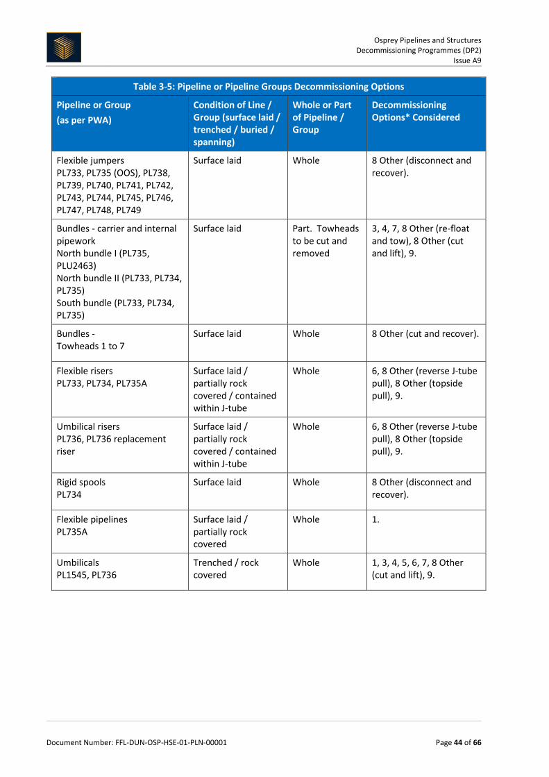
Table 3-5: Pipeline or Pipeline Groups Decommissioning Options
Pipeline or Group (as per PWA)
Condition of Line / Group (surface laid / trenched / buried / spanning)
Whole or Part of Pipeline / Group
Decommissioning Options* Considered
Flexible jumpers PL733, PL735 (OOS), PL738, PL739, PL740, PL741, PL742, PL743, PL744, PL745, PL746, PL747, PL748, PL749
Surface laid Whole 8 Other (disconnect and recover).
Bundles - carrier and internal pipework North bundle I (PL735, PLU2463) North bundle II (PL733, PL734, PL735) South bundle (PL733, PL734, PL735)
Surface laid Part. Towheads to be cut and removed
3, 4, 7, 8 Other (re-float and tow), 8 Other (cut and lift), 9.
Bundles - Towheads 1 to 7
Surface laid Whole 8 Other (cut and recover).
Flexible risers PL733, PL734, PL735A
Surface laid / partially rock covered / contained within J-tube
Whole 6, 8 Other (reverse J-tube pull), 8 Other (topside pull), 9.
Umbilical risers PL736, PL736 replacement riser
Surface laid / partially rock covered / contained within J-tube
Whole 6, 8 Other (reverse J-tube pull), 8 Other (topside pull), 9.
Rigid spools PL734
Surface laid Whole 8 Other (disconnect and recover).
Flexible pipelines PL735A
Surface laid / partially rock covered
Whole 1.
Umbilicals PL1545, PL736
Trenched / rock covered
Whole 1, 3, 4, 5, 6, 7, 8 Other (cut and lift), 9.

Osprey Pipelines and Structures Decommissioning Programmes (DP2)
Issue A9
Document Number: FFL-DUN-OSP-HSE-01-PLN-00001 Page 45 of 66
Table 3-5: Pipeline or Pipeline Groups Decommissioning Options
Pipeline or Group (as per PWA)
Condition of Line / Group (surface laid / trenched / buried / spanning)
Whole or Part of Pipeline / Group
Decommissioning Options* Considered
Umbilicals PL736, PL737, PL754, PL755, PL756, PL757, PL758, PL759, PL760, PL761, PL3001JWP1-7, PL3001JWP4A, PL3960, PL3961, PL3962, PL3963, PL3964, PL3965, PL3966, PL3967, PL3968, PL3969, PL3970, PL3971, PL3972, PL3973, PL3974, PL4975, PL3976, PL3977, PL3978, PL3979, PL3980, PL3981, PL3982, PL3983, PL3984, PL3985, PL3986, PL3987, PL2837, PLU4335, PLU4336, PL4337
Surface laid Whole 8 Other (disconnect and recover).
3.4.2 CA Method
Comparative Assessment is a core part of the overall decommissioning planning and approval process being undertaken by Fairfield for the subsea infrastructure.
Fairfield's strategy for the CA process is aligned with the OGUK guidelines for Comparative Assessment in Decommissioning Programmes (issue 1st October 2015) and DECC's Guidance Notes for the Decommissioning of Offshore Oil and Gas Installations and Pipelines under the Petroleum Act 1998, Version 6, dated: March 2011.
Fairfield has scoped all the associated infrastructure into logical groupings. All feasible decommissioning options for each group have been identified, assessed, ranked and screened to carry forward the credible options to be assessed through the process of CA.
The CA process uses five assessment criteria of Safety, Environment, Technical, Societal and Economic to compare the relative merits of each option. The assessment criteria are equally weighted to balance and represent the views of the associated key stakeholders.
An independent consultancy using its bespoke configurable Multi Criteria Decision Analysis (MCDA) pairwise software was employed to facilitate the CA process. The assessment team comprised of Fairfield specialists and industry / regulatory experts.
For each assessment criteria the team analysed the relative importance of each option against the other options and looked for a differentiator to judge against each other in either a quantitative or qualitative way, using terms such as 'much stronger than' or 'weaker than'. This was input into the software to allow numerical weightings to be derived for the various competing criteria and is a standard part of any MCDA activity. Once all options were assessed and compared, the software completed the ranking to allow the assessment team, including key external stakeholders, to select the preferred decommissioning option per grouping. The CA output is captured in the Osprey CA report FFL-DUN-OSP-HSE-01-RPT-00001 which supports these decommissioning programmes.

Osprey Pipelines and Structures Decommissioning Programmes (DP2)
Issue A9
Document Number: FFL-DUN-OSP-HSE-01-PLN-00001 Page 46 of 66
3.4.3 Outcome of Comparative Assessment [1]
Table 3-6: Outcomes of Comparative Assessment
Pipeline or Group
Recommended Option
Justification
Group 3: Bundles
Option 6 - partial removal. Removal of towheads, rock placement over open ends.
Full removal by cut and lift scored poorly during the CA due to safety, technical and economic factors as did attempting to trench the bundles to below seabed level. A strong preference was shown in the CA workshop for partial removal, with safety, technical and economics being the driving factors which placed it above the other CA options. The outcome of this decision point is therefore to decommission Group 3 in situ by partial removal. The infrastructure will be decommissioned by removing the towheads and intermediate structures and placing rock cover the cut ends, spans and damage. Periodic monitoring and remediation will be carried out as required. Fairfield will consider an approach to periodically review the bundles with a view to selecting a permanent option in the future, e.g. full removal or full rock placement, dependent on technology advances and an associated step change in safety (relative to the other options). Any permanent solution will be discussed and agreed with BEIS.
Group 5: Flexible and umbilical risers (PL733, PL734, PL735 and 2x PL736)
Option 6 - partial removal. Outboard cut and recovery.
Partial removal of the risers, where the outboard and exposed sections of the riser are removed, leaving the remainder in the J-tubes, was assessed as being the preferred option in all criteria apart from societal (in which it was considered neutral to the other CA options). The outcome of this decision point is therefore to decommission Group 5 in situ by partial removal; having recovered the surface laid / exposed sections. The fate of the sections within the J-tube will ultimately be determined by the CA covering the fate of the Dunlin Alpha CGBS. The Osprey - Effect of Riser Remaining Study has been conducted examining the effects of decommissioning the risers in the J-tubes and found the consequence on other activities to be negligible.

Osprey Pipelines and Structures Decommissioning Programmes (DP2)
Issue A9
Document Number: FFL-DUN-OSP-HSE-01-PLN-00001 Page 47 of 66
Table 3-6: Outcomes of Comparative Assessment
Pipeline or Group
Recommended Option
Justification
Group 8: Trenched and rock covered umbilicals (PL736 and PL1545)
Option 6 - partial removal. Removal of exposed ends, rock placement over snag hazards and areas of low cover.
With the exception of the end sections, PL736 is trenched and buried to 0.6 m or greater along the majority of the route. 3,820 t of rock is located on the southern section of the umbilical. With the exception of the end sections PL1545 is laid within a trench that exceeds 0.6 m along the majority of the route. Spot rock dumped is located within the trench every 20 to 25m, totalling 10,895 t. Both PL736 and PL1545 are stable and there is no significant seabed mobility within the vicinity of the lines. Natural backfill of PL1545 is expected to continue at its current slow rate.4 All options considered at the CA were similar however; partial removal exhibited lower levels of personnel exposure, requirement for the addition of new materials and technical challenges. As with all operations, Fairfield will look to minimise safety exposure (to all) and the introduction of new material, to the lowest amount required to ensure confidence in the long term future of the decommissioning solution. The outcome of this decision point is therefore to decommission Group 8 in situ by partial removal by removing exposures outside of the defined trench and placing local rock cover at the cut ends and any areas of low burial depth. Periodic monitoring and remediation will be carried out at this location as required.
4 FBL-DUN-OSP-SSP-01-RPT-00003 Osprey Subsea Assets, Burial Status

Osprey Pipelines and Structures Decommissioning Programmes (DP2)
Issue A9
Document Number: FFL-DUN-OSP-HSE-01-PLN-00001 Page 48 of 66
3.5 Pipeline Stabilisation Features
Table 3-7: Pipeline Stabilisation Features
Stabilisation features Number Option Disposal Route (if applicable)
Concrete mattresses (5 m x 2 m x 0.15 m)
240 Full removal - exposed items presenting a hazard to other users of the sea will be recovered to shore. In the event of practical difficulties with these removals, BEIS will be consulted and a CA submitted as appropriate.
Recover and transport ashore for disposal.
Concrete mattresses (6 m x 2 m x 0.15 m)
8 Full removal - exposed items presenting a hazard to other users of the sea will be recovered to shore. In the event of practical difficulties with these removals, BEIS will be consulted and a CA submitted as appropriate.
Recover and transport ashore for disposal.
Concrete mattresses (6 m x 3 m x 0.15 m)
12 Full removal - exposed items presenting a hazard to other users of the sea will be recovered to shore. In the event of practical difficulties with these removals, BEIS will be consulted and a CA submitted as appropriate.
Recover and transport ashore for disposal.
Concrete mattresses (6m x 3m x 0.3m)
6 Full removal - exposed items presenting a hazard to other users of the sea will be recovered to shore. In the event of practical difficulties with these removals, BEIS will be consulted and a CA submitted as appropriate.
Recover and transport ashore for disposal.
Sand bags 5,295 Full removal - exposed items presenting a hazard to other users of the sea will be recovered to shore. In the event of practical difficulties with these removals, BEIS will be consulted and a CA submitted as appropriate.
Recover and transport ashore for disposal.
Grout bags 280 Full removal - exposed items presenting a hazard to other users of the sea will be recovered to shore. In the event of practical difficulties with these removals, BEIS will be consulted and a CA submitted as appropriate.
Recover and transport ashore for disposal.
Formwork N/A N/A N/A
Frond mats N/A N/A N/A
Rock cover (Te) 18,926 Te To remain in place. N/A

Osprey Pipelines and Structures Decommissioning Programmes (DP2)
Issue A9
Document Number: FFL-DUN-OSP-HSE-01-PLN-00001 Page 49 of 66
3.6 Wells
Table 3-8: Well Plug and Abandonment
The wells which remain to be abandoned, as listed in section 2.4 (Table 2-5) will be plugged and abandoned in accordance with OGUK Guidelines for the Abandonment of Wells, Issue 5, July 2015. A WONS / Portal Environmental Tracking System (PETS) / Marine Licence application will be submitted in support of any such work that is to be carried out.
3.7 Drill Cuttings Drill cuttings decommissioning options:
Table 3-9: Drill Cuttings Decommissioning Options
How many drill cuttings piles are present? Two
Tick options examined:
☐Remove and re-inject ☑Leave in place ☐Cover
☐Relocate on seabed ☐Remove and treat onshore ☐Remove and treat offshore
☐Other (describe briefly) Cuttings from single wells on Osprey will be left in situ.
Review of pile characteristics Pile 1 (Prod)
Pile 2 (WI)
Pile 3 Pile 4
How has the cuttings pile been screened? Samples taken
Samples taken
N/A N/A
Dates of sampling (if applicable) 13 Feb to 3 Apr
2016
13 Feb to 3 Apr
2016
N/A N/A
Sampling to be included in pre-decommissioning survey?
Y Y N/A N/A
Does it fall below both OSPAR thresholds? Y Y N/A N/A
Will the drill cuttings pile have to be displaced in order to remove the jacket?
N/A N/A N/A N/A
What quantity (m3) would have to be displaced / removed?
N/A N/A N/A N/A
Will the drill cuttings pile have to be displaced in order to remove any pipelines?
Y Y N/A N/A
What quantity (m3) would have to be displaced / removed?
146.5 113.0 N/A N/A
Have you carried out a CA of options for the cuttings pile?
N/A N/A N/A N/A

Osprey Pipelines and Structures Decommissioning Programmes (DP2)
Issue A9
Document Number: FFL-DUN-OSP-HSE-01-PLN-00001 Page 50 of 66
3.7.1 CA Method
The cuttings pile survey, sampling and assessment indicated that the cuttings piles on Osprey fall below the OSPAR thresholds and therefore do not require a CA. The Osprey Drill Cuttings are further discussed in the Osprey Environmental Statement (XOD-DUN-HSE-RPT-00004).
3.7.2 Outcome of CA
Not applicable.
3.8 Waste Streams The Fairfield Waste Management Strategy (FEL-DUN-HSE-STR-00003) specifies the requirements for the contractor waste management plan. This will be developed as appropriate once the contract is awarded throughout the project execution phase. The plans shall adhere to the waste stream licensee conditions and controlled accordingly. Discussion with the regulator will ensure that all relevant permits and consents are in place.
Table 3-10: Waste Stream Management Methods
Waste Stream Removal and Disposal method
Bulk liquids Residual fluids within subsea pipelines and associated infrastructure will be discharged in compliance with the appropriate permitry.
Marine growth Any marine growth returned that is attached to recovered items shall be disposed of onshore by the selected WMC.
NORM / LSA scale
NORM / LSA scale will be transported to shore and disposed of by a selected WMC at an appropriately licensed facility.
Asbestos N/A
Other hazardous wastes
All hazardous waste will be shipped to shore and disposed of at an appropriately licensed facility.
Onshore dismantling sites
An appropriately licensed disposal yard has not yet been selected. However, the selection process will ensure that the chosen facility is able to demonstrate a proven disposal track record and waste stream management throughout the deconstruction process, as well as the ability to deliver innovative reuse / recycling options. Locations of potential disposal yards may require the consideration of Trans-Frontier Shipment of Waste (TFSW), including hazardous materials. Early engagement with the regulatory authority will ensure any issues with TFSW are addressed.
Table 3-11 summarises the disposition of materials planned for recovery to shore and materials to be left in situ. Further details can be found within the Osprey Field Infrastructure Comparative Assessment Report.
Table 3-11: Inventory Disposition
Total Inventory Tonnage (Te)
Planned tonnage to shore (Te) Planned left in situ (Te)
Installations 931 931 0
Pipelines 7,193 1,442 5,751
Total 8,124 2,372 5,751

Osprey Pipelines and Structures Decommissioning Programmes (DP2)
Issue A9
Document Number: FFL-DUN-OSP-HSE-01-PLN-00001 Page 51 of 66
Table 3-12 indicates Fairfield's disposal aspirations for materials recovered to shore. Steel and other recyclables will account for the majority of materials to be removed and disposed of and a high rate of recycling (95%) is anticipated. Recycling / other recovery rates for concrete will be dependent on the condition of mattresses and the availability of infrastructure projects. Please refer to section 7.4 of the Osprey Subsea Decommissioning Environmental Statement for further information.
Table 3-12: Waste Disposal Aspirations
Waste Stream Reuse Recycle *Other
Recovery Landfill
Ferrous metal 0 to 15% 95 to 98% 0% 0 to 5%
Non-ferrous metal 0% 95 to 98% 0% 0 to 5%
Concrete (aggregates) 0 to 50% 0% 50 to 100% 0 to 25%
Plastics 0% 50 to 75% 15 to 40% 0 to 10%
Residual hydrocarbons 0% 0% 85 to 100% 0 to 15%
NORM scale 0% 0% 0% **100%
Marine growth 0% 0% 75 to 100% 0 to 25%
* Reuse opportunities will be dependent on availability of infrastructure projects.
** NORM scale may be sent for incineration prior to landfill in order to reduce volume.

Osprey Pipelines and Structures Decommissioning Programmes (DP2)
Issue A9
Document Number: FFL-DUN-OSP-HSE-01-PLN-00001 Page 52 of 66
4 ENVIRONMENTAL IMPACT ASSESSMENT
4.1 Environmental Sensitivities (Summary)
Table 4-1: Environmental Sensitivities
Environmental Receptor Main Features
Conservation interests
None of the survey work undertaken in the Osprey area has identified any seabed habitats or species that are of specific conservation significance, apart from low numbers of juvenile ocean quahog, which is a threatened species. There are no designated or proposed sites of conservation interest in the Osprey area; the closest designated site, the European Site of Community Importance 'Pobie Bank Reef' lies approximately 99 km to the south west of Osprey, off the east coast of Shetland.
Seabed The habitat assessment undertaken for the Osprey area determined the sediments to be mainly muddy sand and mixed sediment. The visible animals found across the survey area included polychaete worms and bivalve crustaceans. Species were generally considered to be intolerant of hydrocarbon contaminations. Surveys showed the seabed to host a relatively diverse range of species, with little variation across the area.
Fish The fish populations in the Osprey area are characterised by species typical of the northern North Sea, including long rough dab, hagfish and Norway pout. Basking shark, tope and porbeagle are all also likely to occur in small numbers. The Osprey area is located within the spawning grounds of cod, haddock, Norway pout and saithe; meaning that these species use the area for breeding. Nursery grounds, where juvenile fish remain to feed and grow, for blue whiting, European hake, haddock, herring, ling, mackerel, Norway pout, spurdog and whiting are also found in the wider area.
Fisheries Saithe and mackerel (often targeted by the larger pelagic vessels in January and February) are the key commercial species landed from the Osprey area. However, they are of relatively low value when compared to total landings into Scotland. Combined, landings of these species from the wider area, within which the Osprey area sits, comprise only 0.06% of the value of landings into Scotland. Other species of commercial value include megrim, cod and monks / anglers.
Marine mammals
Spatially and temporally, harbour porpoises, white-beaked dolphins, minke whales, killer whales and white-sided dolphins are the most regularly sighted cetacean species in the North Sea. Given the distance to shore, species such as the bottlenose dolphin and grey and harbour seals are unlikely to be sighted in the Osprey area.
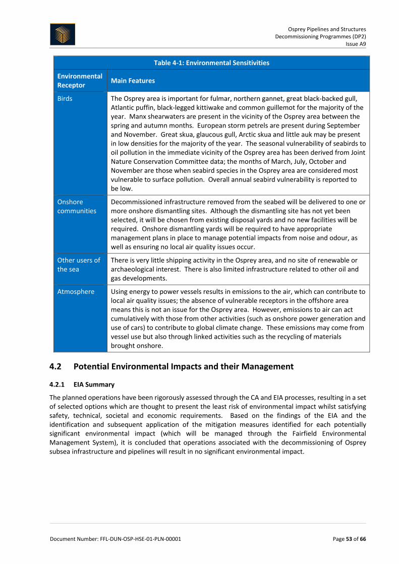
Osprey Pipelines and Structures Decommissioning Programmes (DP2)
Issue A9
Document Number: FFL-DUN-OSP-HSE-01-PLN-00001 Page 53 of 66
Table 4-1: Environmental Sensitivities
Environmental Receptor Main Features
Birds The Osprey area is important for fulmar, northern gannet, great black-backed gull, Atlantic puffin, black-legged kittiwake and common guillemot for the majority of the year. Manx shearwaters are present in the vicinity of the Osprey area between the spring and autumn months. European storm petrels are present during September and November. Great skua, glaucous gull, Arctic skua and little auk may be present in low densities for the majority of the year. The seasonal vulnerability of seabirds to oil pollution in the immediate vicinity of the Osprey area has been derived from Joint Nature Conservation Committee data; the months of March, July, October and November are those when seabird species in the Osprey area are considered most vulnerable to surface pollution. Overall annual seabird vulnerability is reported to be low.
Onshore communities
Decommissioned infrastructure removed from the seabed will be delivered to one or more onshore dismantling sites. Although the dismantling site has not yet been selected, it will be chosen from existing disposal yards and no new facilities will be required. Onshore dismantling yards will be required to have appropriate management plans in place to manage potential impacts from noise and odour, as well as ensuring no local air quality issues occur.
Other users of the sea
There is very little shipping activity in the Osprey area, and no site of renewable or archaeological interest. There is also limited infrastructure related to other oil and gas developments.
Atmosphere Using energy to power vessels results in emissions to the air, which can contribute to local air quality issues; the absence of vulnerable receptors in the offshore area means this is not an issue for the Osprey area. However, emissions to air can act cumulatively with those from other activities (such as onshore power generation and use of cars) to contribute to global climate change. These emissions may come from vessel use but also through linked activities such as the recycling of materials brought onshore.
4.2 Potential Environmental Impacts and their Management
4.2.1 EIA Summary
The planned operations have been rigorously assessed through the CA and EIA processes, resulting in a set of selected options which are thought to present the least risk of environmental impact whilst satisfying safety, technical, societal and economic requirements. Based on the findings of the EIA and the identification and subsequent application of the mitigation measures identified for each potentially significant environmental impact (which will be managed through the Fairfield Environmental Management System), it is concluded that operations associated with the decommissioning of Osprey subsea infrastructure and pipelines will result in no significant environmental impact.
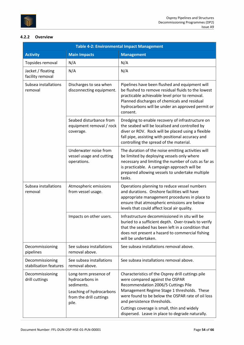
Osprey Pipelines and Structures Decommissioning Programmes (DP2)
Issue A9
Document Number: FFL-DUN-OSP-HSE-01-PLN-00001 Page 54 of 66
4.2.2 Overview
Table 4-2: Environmental Impact Management
Activity Main Impacts Management
Topsides removal N/A N/A
Jacket / floating facility removal
N/A N/A
Subsea installations removal
Discharges to sea when disconnecting equipment.
Pipelines have been flushed and equipment will be flushed to remove residual fluids to the lowest practicable achievable level prior to removal. Planned discharges of chemicals and residual hydrocarbons will be under an approved permit or consent.
Seabed disturbance from equipment removal / rock coverage.
Dredging to enable recovery of infrastructure on the seabed will be localised and controlled by diver or ROV. Rock will be placed using a flexible fall pipe, assisting with positional accuracy and controlling the spread of the material.
Underwater noise from vessel usage and cutting operations.
The duration of the noise emitting activities will be limited by deploying vessels only where necessary and limiting the number of cuts as far as is practicable. A campaign approach will be prepared allowing vessels to undertake multiple tasks.
Subsea installations removal
Atmospheric emissions from vessel usage.
Operations planning to reduce vessel numbers and durations. Onshore facilities will have appropriate management procedures in place to ensure that atmospheric emissions are below levels that could affect local air quality.
Impacts on other users. Infrastructure decommissioned in situ will be buried to a sufficient depth. Over-trawls to verify that the seabed has been left in a condition that does not present a hazard to commercial fishing will be undertaken.
Decommissioning pipelines
See subsea installations removal above.
See subsea installations removal above.
Decommissioning stabilisation features
See subsea installations removal above.
See subsea installations removal above.
Decommissioning drill cuttings
Long-term presence of hydrocarbons in sediments. Leaching of hydrocarbons from the drill cuttings pile.
Characteristics of the Osprey drill cuttings pile were compared against the OSPAR Recommendation 2006/5 Cuttings Pile Management Regime Stage 1 thresholds. These were found to be below the OSPAR rate of oil loss and persistence thresholds. Cuttings coverage is small, thin and widely dispersed. Leave in place to degrade naturally.

Osprey Pipelines and Structures Decommissioning Programmes (DP2)
Issue A9
Document Number: FFL-DUN-OSP-HSE-01-PLN-00001 Page 55 of 66
5 INTERESTED PARTY CONSULTATIONS
5.1 Consultations Summary
Table 5-1: Summary of Stakeholder Comments
Consultee Nature of Engagement Status
Statutory Consultations
National Federation of Fishermen's Organisations
Alan Piggott contacted and consulted on decommissioning scope of work.
National Federation of Fishermen's Organisations (NFFO) to be represented and updated by the Scottish Fishermen's Federation (SFF).
Scottish Fishermen's Federation
SFF participated in the Comparative Assessment process and had a series of face to face engagements during the compilation of the decommissioning programmes. Written comments received during formal consultation period.
Meeting held with Steven Alexander and Raymond Hall in September 2017 to address comments received during the formal consultation period. Written response provided to SFF in December 2017.
Northern Ireland Fishermen’s Federation
Dick James contacted and consulted on decommissioning scope of work.
Northern Ireland Fishermen’s Federation (NIFF) to be represented and updated by the Scottish Fishermen’s Federation (SFF).
Global Marine Systems Limited
John Wrottesley contacted and consulted on decommissioning scope of work.
No impact to other users of the sea in the geographical area.
Other Consultations
UK Fisheries Legacy Trust Fund (FLTC)
Clarifications requested on the scope and timing of the decommissioning proposals.
Meeting held in July 2017 and requested details provided.
Scottish National Heritage (SNH)
Confirmation received from SNH that proposals are outwith SNH jurisdiction, being outside Scottish Territorial Waters (12nm)
No action required.
World Wide Fund for Nature (WWF)
Written comments received during formal consultation period (submitted jointly with WDCS)
Detailed written response provided to WWF and a follow-up engagement meeting held in December 2017.
Whale & Dolphin Conservation Society (WDCS)
Written comments received during formal consultation period (submitted jointly via WWF)
Detailed written response provided via World Wide Fund for Nature (WWF).
Public Fairfield Energy Limited website & email address used for decom materials: http://www.fairfield-energy.com/ [email protected]
No outstanding queries.

Osprey Pipelines and Structures Decommissioning Programmes (DP2)
Issue A9
Document Number: FFL-DUN-OSP-HSE-01-PLN-00001 Page 56 of 66
6 PROGRAMME MANAGEMENT
6.1 Project Management and Verification A Project Management Team (PMT) has been appointed to manage suitable subcontractors for the removal of the Osprey subsea equipment. Standard procedures for operational control and hazard identification and management will be used. Where possible the work will be co-ordinated with other decommissioning operations in the northern North Sea. The PMT will monitor and track the progress of consents and the consultations required as part of this process. Any changes in detail to the offshore removal programme will be controlled by Fairfield via the Management of Change processes and discussed and agreed with BEIS.
6.2 Post-Decommissioning Debris Clearance and Verification During site clearance activities, FFL will undertake reasonable endeavours to recover any dropped objects subject to any outstanding Petroleum Operations Notices (PON). All recovered seabed debris related to offshore oil and gas activities will be returned for onshore disposal or recycling in line with existing disposal methods. A post decommissioning site survey will be carried out around 500 m radius of installation sites and 200 m corridor along each existing pipeline route (100 m either side). Independent verification of seabed state will be obtained by overtrawling the installation site. This will be followed by a statement of clearance to all relevant governmental departments and NGOs. For the pipeline corridors, FFL will conduct a geophysical survey and any oilfield related objects/debris identified will be removed by an ROV. Evidence of a clear seabed will be submitted to OPRED in place of a clear sea bed certificate.
6.3 Schedule
6.3.1 Osprey Project Schedule
2015 2016 2017 2018 2019 2020 2021 2022
Cessation of Production
Infrastructure Make Safe & Handover
Detailed Engineering
Subsea Wells Decommissioning
Contract Strategy Tender & Award
Subsea Infrastructure Removal
Site Clearance (window)
Close Out Report
Earliest Potential Activity
Potential Activity Schedule Windows
15th June 2015

Osprey Pipelines and Structures Decommissioning Programmes (DP2)
Issue A9
Document Number: FFL-DUN-OSP-HSE-01-PLN-00001 Page 57 of 66
Figure 6-1: Gantt Chart of Project Schedule
6.4 Costs FFL are following OGUK Guidelines on Decommissioning Cost Estimation (Issue 3, September 2013) for the decommissioning of the Greater Dunlin Area.
Table 6-1: Provisional Decommissioning Programmes costs
Item Estimated Cost (£m)
Platform preparation / removal and disposal N/A
Pipelines decommissioning Provided to BEIS separately
Subsea installations and stabilisation features Provided to BEIS separately
Well abandonment Provided to BEIS separately
Continuing liability - future pipeline and environmental survey requirements
Provided to BEIS separately
TOTAL Provided to BEIS separately
6.5 Close Out Following completion of the Greater Dunlin Area offshore decommissioning scope, a close out report will be submitted to BEIS and posted on the Fairfield website explaining any variations from the Decommissioning Programmes, in accordance with the requirements in operation at that time. This includes debris removal and independent verification of seabed clearance and the first post-decommissioning environmental survey.
6.6 Post-decommissioning Monitoring and Evaluation A post-decommissioning environmental seabed survey, centred around sites of the wellheads and installations will be carried out. The survey will focus on chemical and physical disturbances of the decommissioning scope of work and be compared with the pre-decommissioning survey. Results of this survey will be available once the work is complete, with a copy forwarded to BEIS. All pipeline routes and installation sites will be the subject of surveys when decommissioning activity has concluded. In addition a baseline survey of the bundle sections shall be undertaken to establish the existing mechanical properties. After the surveys have been sent to BEIS and reviewed, a post monitoring decommissioning survey regime will be agreed by both parties. Typically a minimum of two post-decommissioning environmental surveys and structural pipeline surveys are expected.
The main risk from infrastructure remaining in situ, is the potential for interaction with other sea users, specifically from fishing related activity. Fairfield has conducted material degradation studies that reviewed the anticipated material breakdown of infrastructure left in situ and the effect this could have on other sea users5/6. Where the infrastructure is trenched below seabed level, trenched and buried or contained within the limits of the Dunlin Alpha Platform the effect on other sea users is considered to be negligible. With regards to the bundle sections that are exposed on the seabed, the effect of interaction is more noted. The bundle sections are designed to be over-trawlable however; as the material degrades snag hazards may become evident. It is estimated that snag hazards may appear between 30 and 65 years after decommissioning, dependent on the location along the bundle.
5 A-301649-S01-TECH-001 Osprey - Long Term Materials Degradation Study 6 A-301649-S01-TECH-004 Osprey - Effect of Leaving Riser Section Within J-tube

Osprey Pipelines and Structures Decommissioning Programmes (DP2)
Issue A9
Document Number: FFL-DUN-OSP-HSE-01-PLN-00001 Page 58 of 66
Risks to fishermen have been evaluated, based on the type of fishing activity undertaken within the area, number of crossings made over the infrastructure while actively fishing and the seabed condition due to the installation features of the infrastructure7, e.g. construction berms, areas of low cover, exposed sections, etc.
For the trenched infrastructure the potential loss of life due to snagging, after decommissioning, is in the order of 2.85E-06 (fatality frequency of 1 in 350,877 years).
For the trenched and buried infrastructure the potential loss of life due to snagging, after decommissioning, is in the order of 3.78E-07 (fatality frequency of 1 in 2,645,502 years).
For the exposed bundle infrastructure the potential loss of life due to snagging, after decommissioning, is in the order of 4.14E-06 (fatality frequency of 1 in 241,545 years) for the North Bundle and 3.02E-05 (fatality frequency of 1 in 33,112 years) for the South Bundle.
The infrastructure is currently shown on Admiralty Charts and the FishSafe system. Once decommissioning activities are complete, updated information on the Osprey subsea area, i.e. which infrastructure remains in situ and which has been removed, will be made available to allow the Admiralty Charts and the FishSafe system to be updated and the subsea 500 m zones to be removed.
Due to the location and low seabed mobility, infrastructure remaining in situ that is trenched or trenched and buried is unlikely to become exposed. For the exposed bundle sections, excessive spanning is unlikely to occur. Should future surveys find evidence of any exposures, spans or interactions that exceed the FishSafe criteria, these will be submitted for inclusion within the FishSafe database.
Fairfield recognises its commitment to monitor any structures decommissioned in situ and therefore intends to set up arrangements to undertake post-decommissioning monitoring on behalf of the licence owners. The frequency of required monitoring will be agreed with BEIS and future monitoring will be determined through a risk-based approach based on the findings from each subsequent survey. During the period over which monitoring is required, the status of the infrastructure decommissioned in situ would be reviewed and any necessary remedial action undertaken to ensure it does not pose a risk to other sea users. Further details are provided within the ES section 6.2.3.
On an annual basis for a period of 10 years post-decommissioning programme approval, FEL will submit a report to OPRED detailing Osprey bundle removal feasibility, assessment and evaluation for consideration by OPRED Decommissioning Unit representatives.
In addition FEL will contribute in the development of techniques to remove to shore large diameter subsea pipeline bundles of the size of the Osprey Field pipeline bundle and will actively participate in opportunities for JIP and any other relevant approaches, to stimulate the supply chain with respect to removal techniques for such large diameter subsea pipeline bundles.
7 A-3910-XG-RA-1 Dunlin, Osprey & Merlin Subsea Infrastructure Decommissioning Fishing Risk Assessment

Osprey Pipelines and Structures Decommissioning Programmes (DP2)
Issue A9
Document Number: FFL-DUN-OSP-HSE-01-PLN-00001 Page 59 of 66
7 SUPPORTING DOCUMENTS
Table 7-1: Supporting Documents
Document Number Title
1) FFL-DUN-OSP-HSE-01-RPT-00001 Osprey Comparative Assessment Report
2) XOD-DUN-HSE-RPT-00004 (Xodus) Osprey Environmental Statement
3) FFL-DUN-OSP-HSE-01-RPT-00002 Osprey Cost Summary Report (confidential, issued to BEIS only)
4) FBL-DUN-DAOM-HSE-01-PLN-00001 Greater Dunlin Area DP Bridging Doc
For latest document versions see http://www.fairfield-energy.com/

Osprey Pipelines and Structures Decommissioning Programmes (DP2)
Issue A9
Document Number: FFL-DUN-OSP-HSE-01-PLN-00001 Page 60 of 66
8 PARTNER LETTER OF SUPPORT

Osprey Pipelines and Structures Decommissioning Programmes (DP2)
Issue A9
Document Number: FFL-DUN-OSP-HSE-01-PLN-00001 Page 61 of 66
9 APPENDIX 1 – STATUTORY CONSULTEE CORRESPONDENCE
Global Marine Systems (GMS) Ltd.
Point of contact: John Wrottesley
Summary - Introduction made on 13th May 2016, follow up made on 20th May 2016, Greater Dunlin Area Decommissioning has no impact to others in the geographical area.
Scottish Fishermen’s Federation, incorporating:
Anglo-Scottish Fishermen's Association Clyde Fishermen's Association Fife Fishermen's Association Fishing Vessel Agents & Owners Association (Scotland) Limited Mallaig and North-West Fishermen's Association Limited Orkney Fisheries Association Scallop Association Scottish Pelagic Fishermen's Association Limited Scottish White Fish Producers' Association Limited (SWFPA) Shetland Fishermen's Association
Point of contact: Steven Alexander / Raymond Hall
Summary of meetings:
Jan 2010 (21st) Workshop Introduction to Greater Dunlin Area May 2010 Document Reuse report June 2010 (8th) Meeting Briefing Jul 2010 Document Re-float report #1 May 2011 (12th) Meeting Briefing Jun 2011 Document Cell contents Impact Assessment Jul 2011 Document Access to legs and cells report Aug 2011 Document Re-float report #2 Oct 2011 (7th) Meeting Briefing Oct 2011 Document In situ decom options Nov 2011 Document In situ decom options Dec 2015 (22nd) Meeting Consultation Mar 2016 (4th) Meeting Subsea CA option coarse screening Dec 2016 (8th) Meeting CA briefing session Jan 2017 (10th) Workshop Comparative Assessment Sept 2017 (8th) Meeting Clarifications to public consultation documentation Nov 2017 (30th) Letter Formal correspondence to public consultation SFF letter
National Federation of Fishermen's Organisations (NFFO)
Point of contact: Alan Piggott
Summary – Introduction made on 31st May 2016, NFFO requested to be represented and updated by SFF.

Osprey Pipelines and Structures Decommissioning Programmes (DP2)
Issue A9
Document Number: FFL-DUN-OSP-HSE-01-PLN-00001 Page 62 of 66
Northern Ireland Fishermen’s Federation
Point of contact: Dick James
Summary - Introduction made on 31st May 2016, NIFPO requested to be represented and updated by SFF.
General Public
Identified external stakeholders / organisations have been emailed to raise awareness of the Greater Dunlin Area decommissioning programmes. Notifications made through applicable press releases. Formally engaged with general public upon submission of the Consultation Draft of the Decommissioning Programmes prior to the 30 day public consultation period.

Osprey Pipelines and Structures Decommissioning Programmes (DP2)
Issue A9
Document Number: FFL-DUN-OSP-HSE-01-PLN-00001 Page 63 of 66
10 APPENDIX 2 – PUBLIC NOTICES
The Shetland Times printed June 23rd 2017:

Osprey Pipelines and Structures Decommissioning Programmes (DP2)
Issue A9
Document Number: FFL-DUN-OSP-HSE-01-PLN-00001 Page 64 of 66
The Press and Journal printed June 23rd 2017:

Osprey Pipelines and Structures Decommissioning Programmes (DP2)
Issue A9
Document Number: FFL-DUN-OSP-HSE-01-PLN-00001 Page 65 of 66
The Edinburgh Gazette printed 26th June 2017, number 27888 (available online 21st to 25th June 2017):
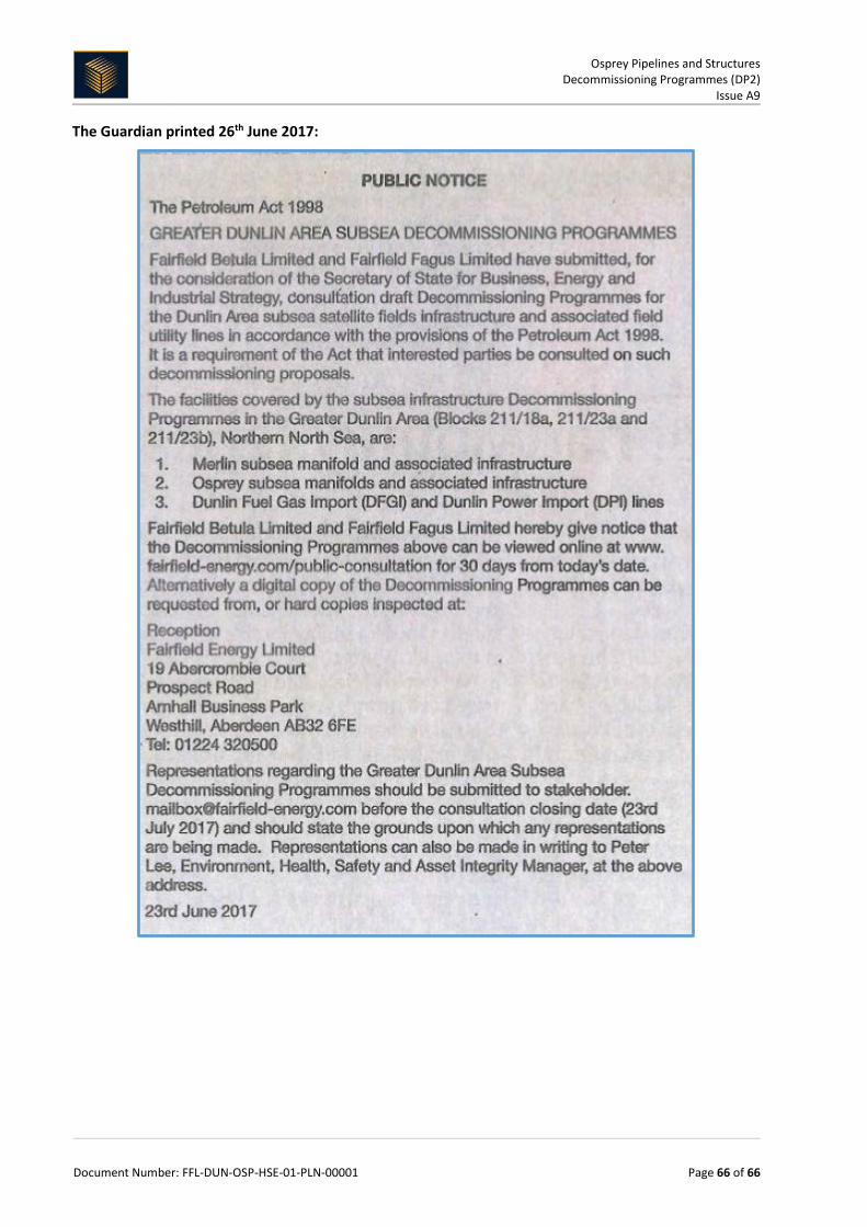
Osprey Pipelines and Structures Decommissioning Programmes (DP2)
Issue A9
Document Number: FFL-DUN-OSP-HSE-01-PLN-00001 Page 66 of 66
The Guardian printed 26th June 2017: