fast-cast 550 series spreaders -...
TRANSCRIPT

®™
Fast-Cast 1CS6H - Aluminum Hopper with S.S. BodyFast-Cast 1CS6CPH - Poly Hopper with Carbon Steel Body
1 of 15
FAST-CAST 550 SERIES SPREADERS
Curtis Industries Inc. LLC, 111 Higgins St., Worcester, MA 01606 TEL: (800) 343-7676 FAX: (508) 854-3377 For Parts and information visit us at www.Curtisindustries.netCurtis Industries Inc. LLC, reserves the right to change product design or specifications without notice or liability.
Assembly and Owner's Manual - September 2010
1CS6CPH
2 of 15
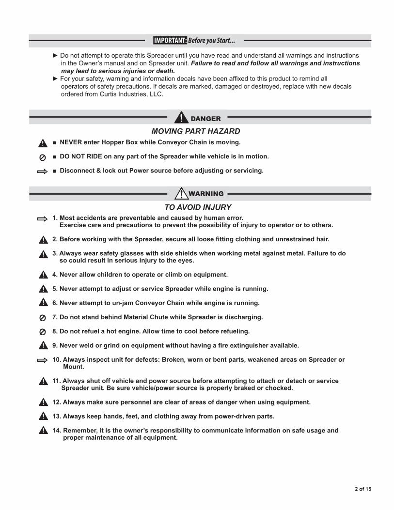
►DonotattempttooperatethisSpreaderuntilyouhavereadandunderstandallwarningsandinstructions intheOwner’smanualandonSpreaderunit.Failure to read and follow all warnings and instructions may lead to serious injuries or death. ►Foryoursafety,warningandinformationdecalshavebeenaffixedtothisproducttoremindall operatorsofsafetyprecautions.Ifdecalsaremarked,damagedordestroyed,replacewithnewdecals orderedfromCurtisIndustries,LLC.
IMPORTANT: Before you Start...
1. Most accidents are preventable and caused by human error. Exercise care and precautions to prevent the possibility of injury to operator or to others.
2. Before working with the Spreader, secure all loose fitting clothing and unrestrained hair.
3. Always wear safety glasses with side shields when working metal against metal. Failure to do so could result in serious injury to the eyes.
4. Never allow children to operate or climb on equipment.
5. Never attempt to adjust or service Spreader while engine is running.
6. Never attempt to un-jam Conveyor Chain while engine is running.
7. Do not stand behind Material Chute while Spreader is discharging.
8. Do not refuel a hot engine. Allow time to cool before refueling.
9. Never weld or grind on equipment without having a fire extinguisher available.
10. Always inspect unit for defects: Broken, worn or bent parts, weakened areas on Spreader or Mount.
11. Always shut off vehicle and power source before attempting to attach or detach or service Spreader unit. Be sure vehicle/power source is properly braked or chocked.
12. Always make sure personnel are clear of areas of danger when using equipment.
13. Always keep hands, feet, and clothing away from power-driven parts.
14. Remember, it is the owner’s responsibility to communicate information on safe usage and proper maintenance of all equipment.
■ NEVER enter Hopper Box while Conveyor Chain is moving.
■ DO NOT RIDE on any part of the Spreader while vehicle is in motion.
■ Disconnect & lock out Power source before adjusting or servicing.
DANGER
WARNING
MOVING PART HAZARD
TO AVOID INJURY
3 of 15
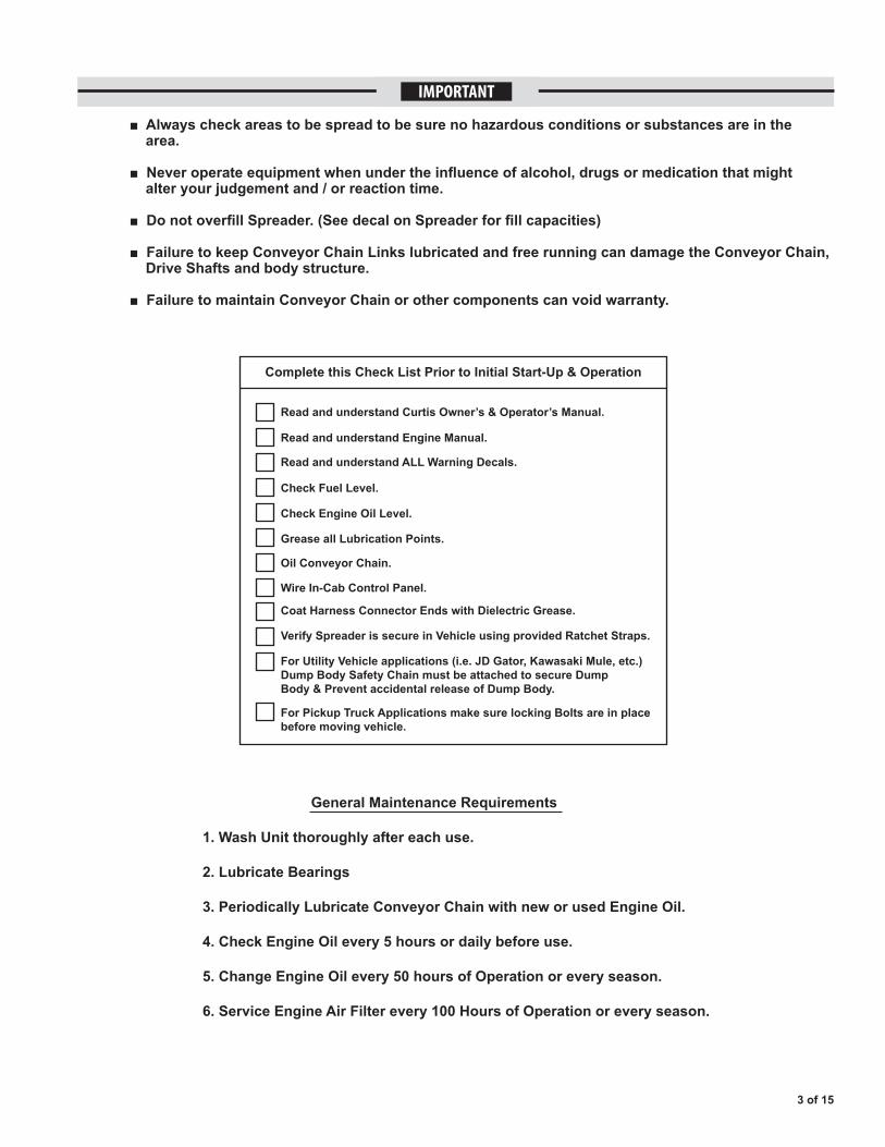
IMPORTANT
■ Always check areas to be spread to be sure no hazardous conditions or substances are in the area.
■ Never operate equipment when under the influence of alcohol, drugs or medication that might alter your judgement and / or reaction time.
■ Do not overfill Spreader. (See decal on Spreader for fill capacities)
■ Failure to keep Conveyor Chain Links lubricated and free running can damage the Conveyor Chain, Drive Shafts and body structure.
■ Failure to maintain Conveyor Chain or other components can void warranty.
Complete this Check List Prior to Initial Start-Up & Operation
Read and understand Curtis Owner’s & Operator’s Manual.
Read and understand Engine Manual.
Read and understand ALL Warning Decals.
Check Fuel Level.
Check Engine Oil Level.
Grease all Lubrication Points.
Oil Conveyor Chain.
Wire In-Cab Control Panel.
Coat Harness Connector Ends with Dielectric Grease.
Verify Spreader is secure in Vehicle using provided Ratchet Straps.
For Utility Vehicle applications (i.e. JD Gator, Kawasaki Mule, etc.)Dump Body Safety Chain must be attached to secure DumpBody & Prevent accidental release of Dump Body.
For Pickup Truck Applications make sure locking Bolts are in placebefore moving vehicle.
General Maintenance Requirements
1. Wash Unit thoroughly after each use.
2. Lubricate Bearings
3. Periodically Lubricate Conveyor Chain with new or used Engine Oil.
4. Check Engine Oil every 5 hours or daily before use.
5. Change Engine Oil every 50 hours of Operation or every season.
6. Service Engine Air Filter every 100 Hours of Operation or every season.
When choosing a location for the Control Panel, do not position the Panel in line with the Driver’s or Passenger’s seat to ensure the Control Panel is not hit accidentally. 1D. Body Safety Chain Installation
For UTV applications: A Dump Body Safety Chain must be attached to secure the Dump Body and prevent the accidental release of the Dump Body.
InstallEyeboltstoVehicleFrameandDumpBodyoftheUtilityVehicle.Usinga32"ChainandaOneLinkConnector,attachChaintotheEyeboltsmountedtotheFrameandDumpBody.SafetyChainsaretobeusedinconjunctionwiththeHoldDownAssemblies.AttachingaChainwillpreventanaccidentalreleaseoftheDumpBody.TheChain/EyeboltsetupisnotrequiredforPickuptruckapplications.
Section 1. Installation Instructions
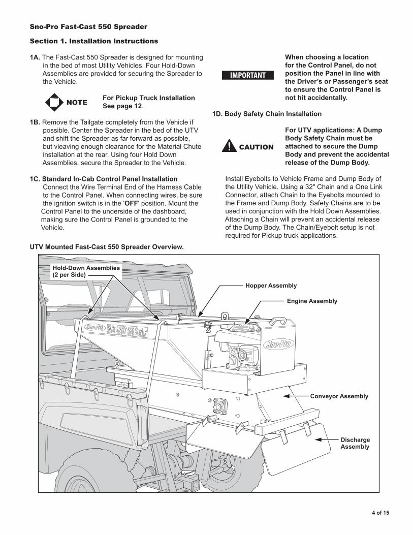
1A.TheFast-Cast550SpreaderisdesignedformountinginthebedofmostUtilityVehicles.FourHold-DownAssembliesareprovidedforsecuringtheSpreadertotheVehicle.
For Pickup Truck Installation See page 12.
1B.RemovetheTailgatecompletelyfromtheVehicleifpossible.CentertheSpreaderinthebedoftheUTVandshifttheSpreaderasfarforwardaspossible,butvleavingenoughclearancefortheMaterialChuteinstallationattherear.UsingfourHoldDownAssemblies,securetheSpreadertotheVehicle.
1C.Standard In-Cab Control Panel Installation ConnecttheWireTerminalEndoftheHarnessCabletotheControlPanel.Whenconnectingwires,besuretheignitionswitchisinthe'OFF'position.MounttheControlPaneltotheundersideofthedashboard,makingsuretheControlPanelisgroundedtotheVehicle.
UTV Mounted Fast-Cast 550 Spreader Overview.
Hopper Assembly
Conveyor Assembly
Engine Assembly
DischargeAssembly
Hold-Down Assemblies(2 per Side)
IMPORTANT
4 of 15
Sno-Pro Fast-Cast 550 Spreader
CAUTION
NOTE
5 of 15
Sno-Pro Fast-Cast 550 Spreader
1D. (continued)
Failure to attach this Chain may result in an accidental Body Dump, damaging the Spreader, the Utility Vehicle, persons seated in the Vehicle, or standing nearby.
Section 2. Operating Instructions
2A. Engine Starting and Cab Controls
Step 1.Verifythatthe'ON/OFF'Switchisinthe 'ON/RUN'positionontheCabControlPanel.
Step 2.GotoEngineattherearofSpreader.MovetheThrottleControltothe'FAST'Position. PushPrimerBulbfirmly3-5times. GraspRopeHandleandpullcordrapidlytostartEngine.(SeeEnginemanualfordetails.)
Step 3.FromtheCabControlPanel,fliptheConveyorSwitchtothe'ON'position.ThiswillengagetheConveyorChainandSpinnerDisc.TheIndicatorwillcomeon.
2B. Gate Height Adjustment Steps
Step 1. LoosentwoGateScrews.
Step 2.AdjustGatetodesiredheight.
Step 3.TightenGateScrews.
2C. Material Chute Deflectors
AdjusttheMaterialDeflectorstofinetunethespreadpattern.KeepallMaterialDeflectorsatthesameangle.Foralargerspreadpattern:RaiseDeflectors.Forasmallerspreadpattern:LowerDeflectors.
Never attempt to adjust Material Deflectors while Spreader is operating.
2D. Conveyor Chain Adjustment
TightenbothTake-UpBoltsequallyuntilslackisgoneintheConveyorChain.
After adjusting the Conveyor Chain, verify that the Take-Up Shaft is not at an angle.
Never attempt to adjust Conveyor Chain while Spreader Engine is running.
2E. Fast-Cast 550 Spreader Storage
1.)WashUnitThoroughly 2.)OilConveyorChain 3.)LubricateAllBearings
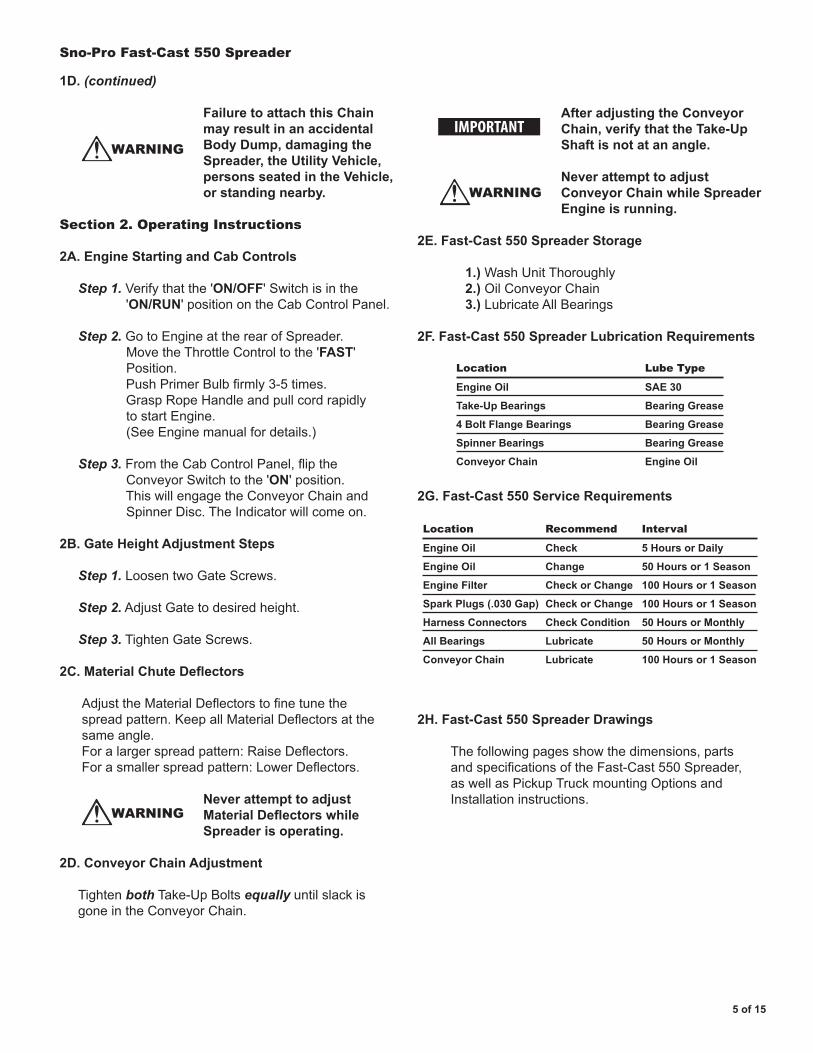
2F. Fast-Cast 550 Spreader Lubrication Requirements
2G. Fast-Cast 550 Service Requirements
2H. Fast-Cast 550 Spreader Drawings
Thefollowingpagesshowthedimensions,partsandspecificationsoftheFast-Cast550Spreader,aswellasPickupTruckmountingOptionsandInstallationinstructions.
WARNING
WARNING
IMPORTANT
WARNING
Location
Engine Oil
Take-Up Bearings
4 Bolt Flange Bearings
Spinner Bearings
Conveyor Chain
Lube Type
SAE 30
Bearing Grease
Bearing Grease
Bearing Grease
Engine Oil
Location
Engine Oil
Engine Oil
Engine Filter
Spark Plugs (.030 Gap)
Harness Connectors
All Bearings
Conveyor Chain
Interval
5 Hours or Daily
50 Hours or 1 Season
100 Hours or 1 Season
100 Hours or 1 Season
50 Hours or Monthly
50 Hours or Monthly
100 Hours or 1 Season
Recommend
Check
Change
Check or Change
Check or Change
Check Condition
Lubricate
Lubricate
Sno-Pro Fast-Cast 550 Spreader
6 of 15
40.00
33.38
REAR VIEW
SIDE VIEWREAR VIEW58.50
23.50
37.00
38.00
12
3
4
6
8
7
9
5
11
10
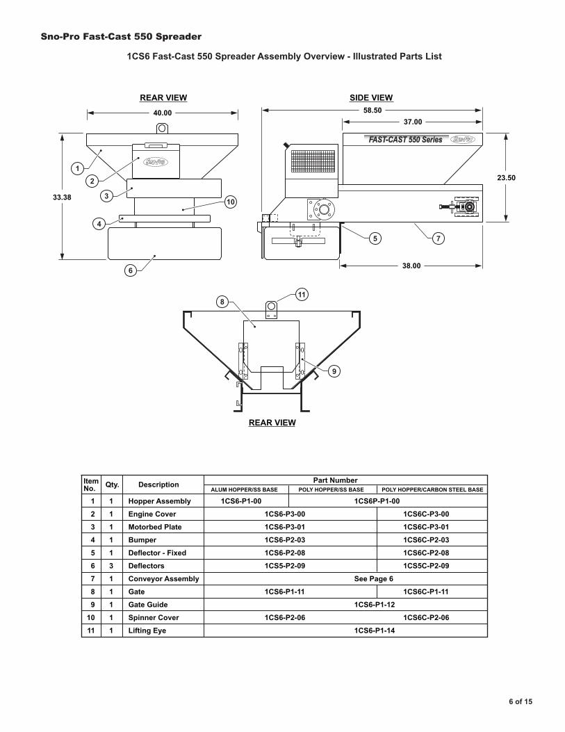
1CS6 Fast-Cast 550 Spreader Assembly Overview - Illustrated Parts List
1
2
3
4
5
6
7
8
9
10
11
1CS6-P1-00
1CS6-P3-00
1CS6-P3-01
1CS6-P2-03
1CS6-P2-08
1CS5-P2-09
1CS6-P1-11
1CS6-P2-06
1CS6C-P3-00
1CS6C-P3-01
1CS6C-P2-03
1CS6C-P2-08
1CS5C-P2-09
1CS6C-P1-11
1CS6C-P2-06
1CS6P-P1-00
See Page 6
1CS6-P1-12
1CS6-P1-14
Hopper Assembly
Engine Cover
Motorbed Plate
Bumper
Deflector - Fixed
Deflectors
Conveyor Assembly
Gate
Gate Guide
Spinner Cover
Lifting Eye
ItemNo.
1
1
1
1
1
3
1
1
1
1
1
Qty. Description Part NumberALUM HOPPER/SS BASE POLY HOPPER/SS BASE POLY HOPPER/CARBON STEEL BASE
®
®
FAST-CAST 550 Series
Sno-Pro Fast-Cast 550 Spreader
7 of 15
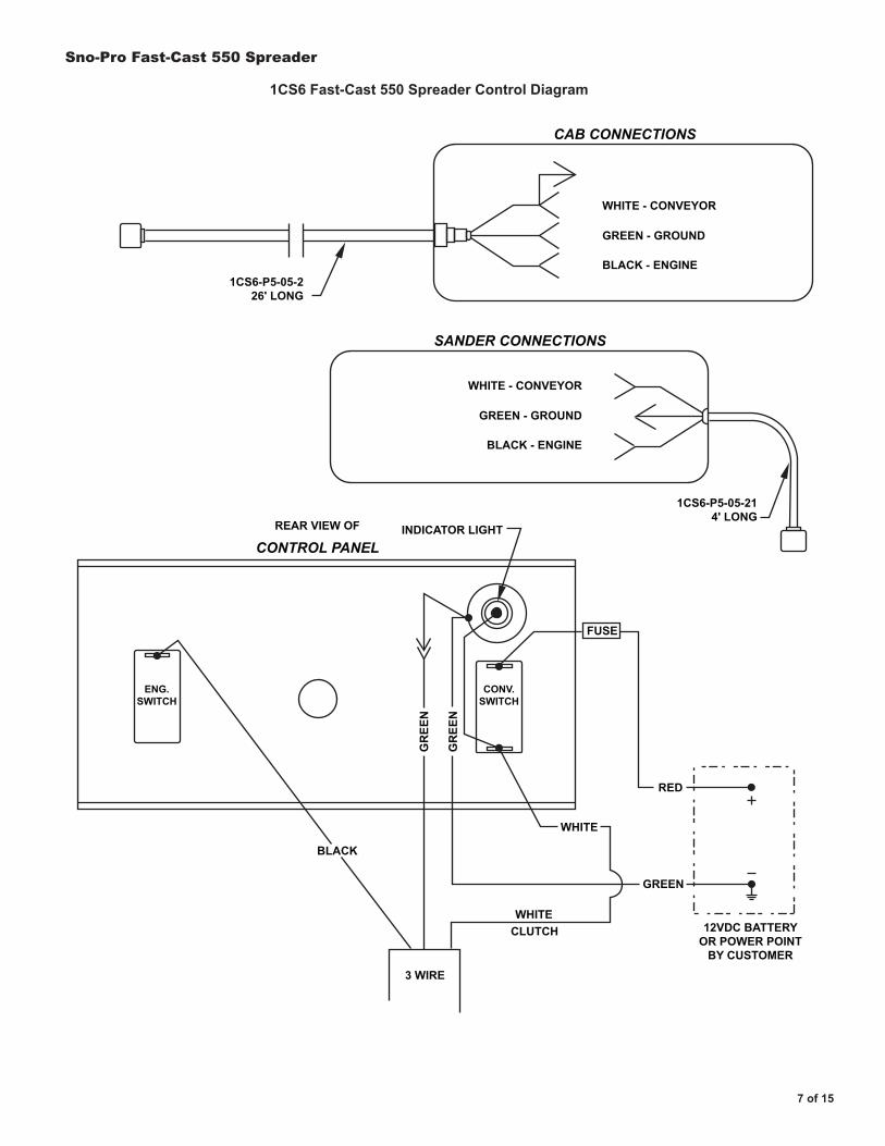
CAB CONNECTIONS
WHITE - CONVEYOR
GREEN - GROUND
BLACK - ENGINE
WHITE - CONVEYOR
1CS6-P5-05-226' LONG
1CS6-P5-05-214' LONG
INDICATOR LIGHTREAR VIEW OF
BLACK
GREEN
RED
12VDC BATTERYOR POWER POINT
BY CUSTOMER
FUSE
WHITE
WHITE
CONV.SWITCH
ENG.SWITCH
CLUTCH
3 WIRE
GR
EEN
GR
EEN
GREEN - GROUND
BLACK - ENGINE
SANDER CONNECTIONS
CONTROL PANEL
1CS6 Fast-Cast 550 Spreader Control Diagram
Sno-Pro Fast-Cast 550 Spreader
8 of 15
REARVIEW A - A
1
14
19 17 125
18
TOPA A
13
4
15
7
6
11
Side Viewtypical of both sides
9
8
16
3
102
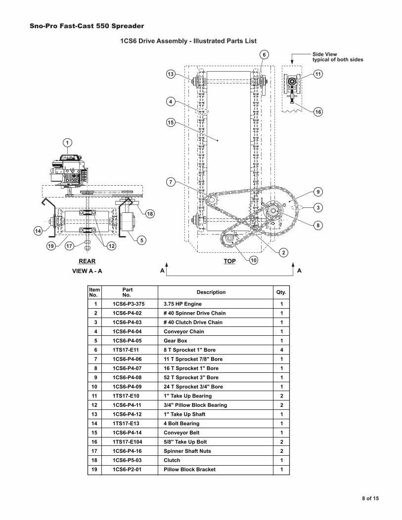
1CS6 Drive Assembly - Illustrated Parts List
1
2
3
4
5
6
7
8
9
10
11
12
13
14
15
16
17
18
19
1CS6-P3-375
1CS6-P4-02
1CS6-P4-03
1CS6-P4-04
1CS6-P4-05
1TS17-E11
1CS6-P4-06
1CS6-P4-07
1CS6-P4-08
1CS6-P4-09
1TS17-E10
1CS6-P4-11
1CS6-P4-12
1TS17-E13
1CS6-P4-14
1TS17-E104
1CS6-P4-16
1CS6-P5-03
1CS6-P2-01
3.75 HP Engine
# 40 Spinner Drive Chain
# 40 Clutch Drive Chain
Conveyor Chain
Gear Box
8 T Sprocket 1" Bore
11 T Sprocket 7/8" Bore
16 T Sprocket 1" Bore
52 T Sprocket 3" Bore
24 T Sprocket 3/4" Bore
1" Take Up Bearing
3/4" Pillow Block Bearing
1" Take Up Shaft
4 Bolt Bearing
Conveyor Belt
5/8" Take Up Bolt
Spinner Shaft Nuts
Clutch
Pillow Block Bracket
ItemNo.
1
1
1
1
1
4
1
1
1
1
2
2
1
1
1
2
2
1
1
Qty.PartNo. Description
Sno-Pro Fast-Cast 550 Spreader
9 of 15
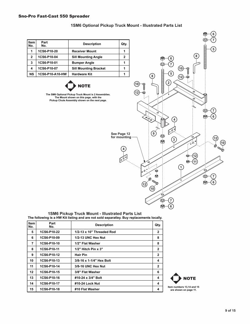
1SM6 Optional Pickup Truck Mount - Illustrated Parts List
1SM6 Pickup Truck Mount - Illustrated Parts List
ItemNo.
5
6
7
8
9
10
11
12
13
14
15
1CS6-P10-22
1CS6-P10-09
1CS6-P10-10
1CS6-P10-11
1CS6-P10-12
1CS6-P10-13
1CS6-P10-14
1CS6-P10-15
1CS6-P10-16
1CS6-P10-17
1CS6-P10-18
1/2-13 x 10" Threaded Rod
1/2-13 UNC Hex Nut
1/2" Flat Washer
1/2" Hitch Pin x 3"
Hair Pin
3/8-16 x 1-1/4" Hex Bolt
3/8-16 UNC Hex Nut
3/8" Flat Washer
#10-24 x 3/4" Bolt
#10-24 Lock Nut
#10 Flat Washer
2
8
8
2
2
4
2
6
4
4
4
Qty.PartNo. Description
The following is a HW Kit listing and are not sold separatley. Buy replacements locally.
6
9See Page 12for mounting
7
10
12
12
11
1012
1012
10
125
6
7
6
7
6
7
6
7
5
8
4
4
8
2
3
1
The SM6 Optional Pickup Truck Mount is 2 Assemblies.The Mount shown on this page, with the
Pickup Chute Assembly shown on the next page.
1
2
3
4
NS
1CS6-P10-20
1CS6-P10-04
1CS6-P10-01
1CS6-P10-07
1CS6-P10-A10-HW
Receiver Mount
Sill Mounting Angle
Bumper Angle
Sill Mounting Bracket
Hardware Kit
ItemNo.
1
2
1
1
1
Qty.PartNo. Description
NOTE
Item numbers 13,14 and 15are shown on page 11.
NOTE
Sno-Pro Fast-Cast 550 Spreader
10 of 15
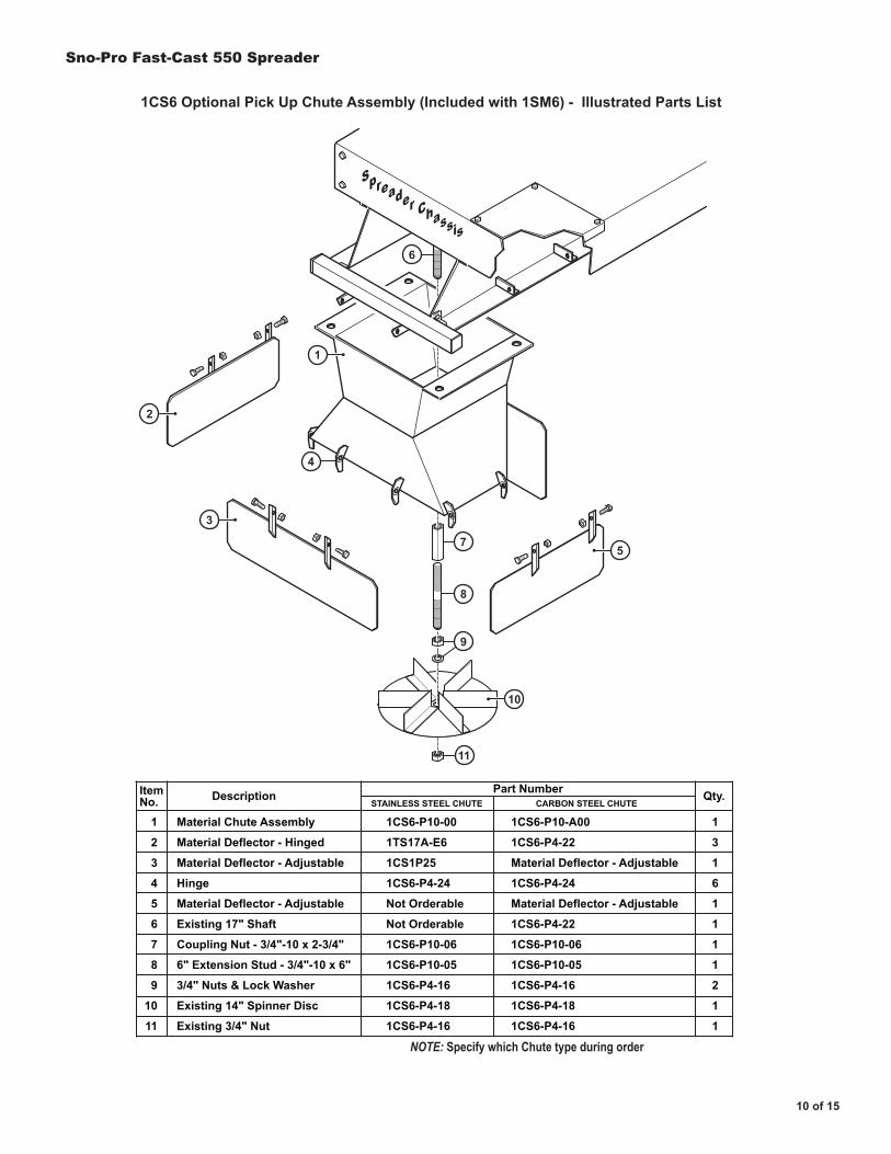
1CS6 Optional Pick Up Chute Assembly (Included with 1SM6) - Illustrated Parts List
1
2
3
4
5
6
7
8
9
10
11
1CS6-P10-00
1TS17A-E6
1CS1P25
1CS6-P4-24
Not Orderable
Not Orderable
1CS6-P10-06
1CS6-P10-05
1CS6-P4-16
1CS6-P4-18
1CS6-P4-16
Material Chute Assembly
Material Deflector - Hinged
Material Deflector - Adjustable
Hinge
Material Deflector - Adjustable
Existing 17" Shaft
Coupling Nut - 3/4"-10 x 2-3/4"
6" Extension Stud - 3/4"-10 x 6"
3/4" Nuts & Lock Washer
Existing 14" Spinner Disc
Existing 3/4" Nut
1CS6-P10-A00
1CS6-P4-22
Material Deflector - Adjustable
1CS6-P4-24
Material Deflector - Adjustable
1CS6-P4-22
1CS6-P10-06
1CS6-P10-05
1CS6-P4-16
1CS6-P4-18
1CS6-P4-16
ItemNo.
1
3
1
6
1
1
1
1
2
1
1
Qty.Part NumberDescriptionSTAINLESS STEEL CHUTE CARBON STEEL CHUTE
NOTE: Specify which Chute type during order
6
4
9
8
7
11
Spreader Chassis
2
1
3
5
10
Sno-Pro Fast-Cast 550 Spreader
11 of 15
14
15
13
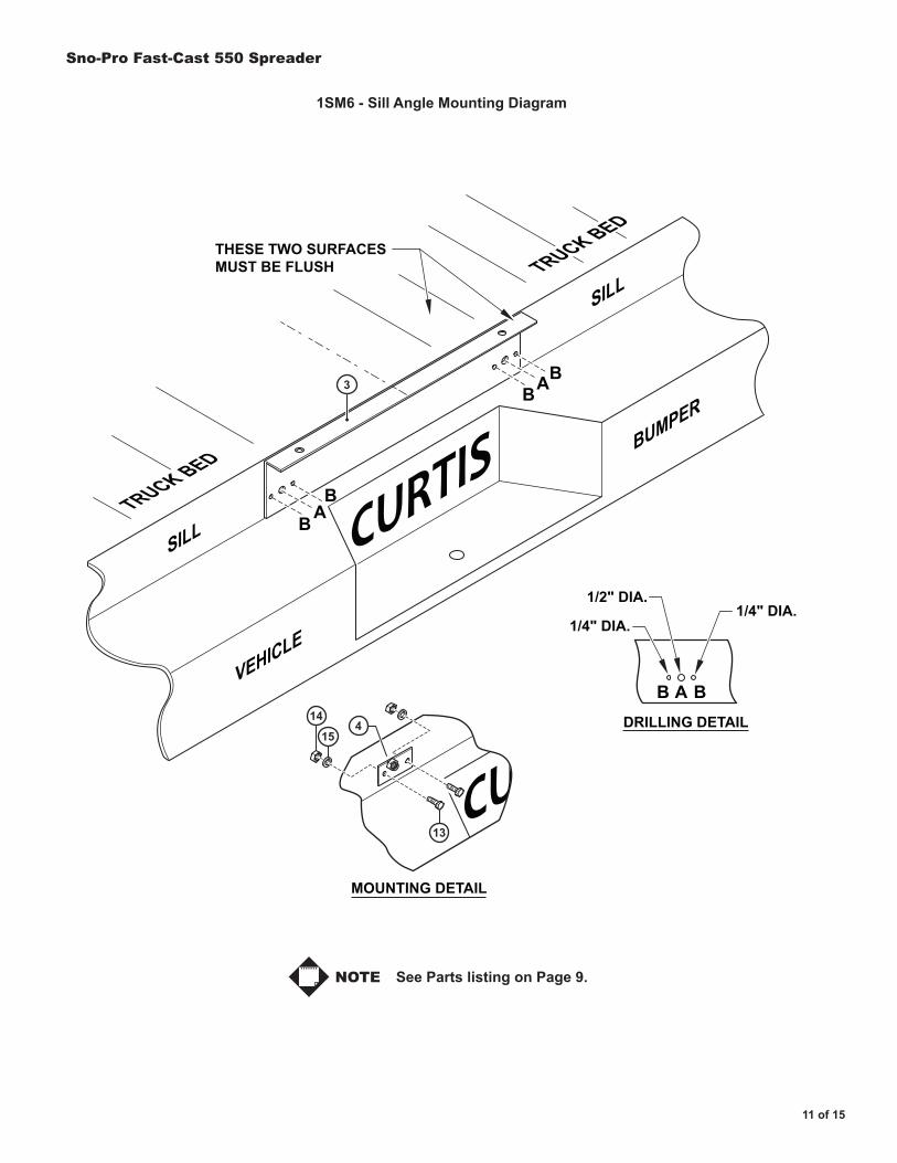
CURTIS
CU
B
B BA
BA
BBA
SILL
SILL
VEHICLE
BUMPER
THESE TWO SURFACESMUST BE FLUSH
MOUNTING DETAIL
DRILLING DETAIL
1/4" DIA.1/4" DIA.
1/2" DIA.
TRUCK BED
TRUCK BED
3
4
1SM6 - Sill Angle Mounting Diagram
See Parts listing on Page 9. NOTE
Sno-Pro Fast-Cast 550 Spreader
12 of 15
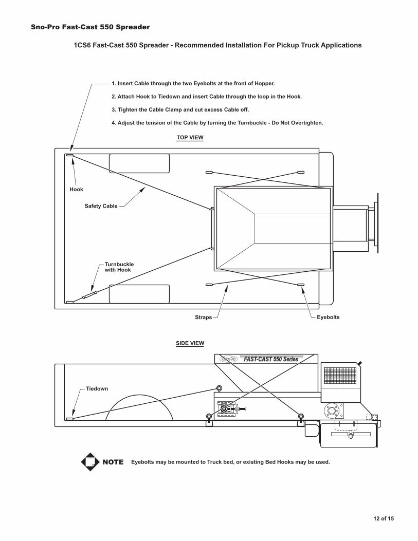
1CS6 Fast-Cast 550 Spreader - Recommended Installation For Pickup Truck Applications
Eyebolts may be mounted to Truck bed, or existing Bed Hooks may be used.
® FAST-CAST 550 Series
Turnbucklewith Hook
Straps
Tiedown
Safety Cable
Eyebolts
TOP VIEW
SIDE VIEW
Hook
1. Insert Cable through the two Eyebolts at the front of Hopper.
2. Attach Hook to Tiedown and insert Cable through the loop in the Hook.
3. Tighten the Cable Clamp and cut excess Cable off.
4. Adjust the tension of the Cable by turning the Turnbuckle - Do Not Overtighten.
NOTE

Sno-Pro Fast-Cast 550 Spreader
13 of 15
1
3
2
Mark and drill holein Lifting Eyefor 1/4" Fastener
1
2
3
1CS6-P10-32
1CS6-P10-33
1CS6-P10-34
Screen - 550 Mini
1/4-20 x 3/4" HHCS
1/4-20 Hex Nut
ItemNo.
1
1
1
Qty.PartNo. Description
1CS6 Fast-Cast 550 Spreader Screen Option - Illustrated Parts List
Sno-Pro Fast-Cast 550 Spreader
14 of 15
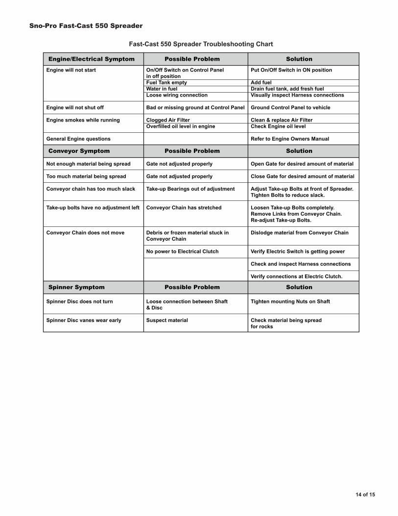
Engine will not start
Engine will not shut off
Engine smokes while running
General Engine questions
Not enough material being spread
Too much material being spread
Conveyor chain has too much slack
Take-up bolts have no adjustment left
Conveyor Chain does not move
Spinner Disc does not turn
Spinner Disc vanes wear early
On/Off Switch on Control Panelin off positionFuel Tank emptyWater in fuelLoose wiring connection
Bad or missing ground at Control Panel
Clogged Air FilterOverfilled oil level in engine
Gate not adjusted properly
Gate not adjusted properly
Take-up Bearings out of adjustment
Conveyor Chain has stretched
Debris or frozen material stuck inConveyor Chain
No power to Electrical Clutch
Loose connection between Shaft& Disc
Suspect material
Put On/Off Switch in ON position
Add fuelDrain fuel tank, add fresh fuelVisually inspect Harness connections
Ground Control Panel to vehicle
Clean & replace Air FilterCheck Engine oil level
Refer to Engine Owners Manual
Open Gate for desired amount of material
Close Gate for desired amount of material
Adjust Take-up Bolts at front of Spreader.Tighten Bolts to reduce slack.
Loosen Take-up Bolts completely.Remove Links from Conveyor Chain.Re-adjust Take-up Bolts.
Dislodge material from Conveyor Chain
Verify Electric Switch is getting power
Check and inspect Harness connections
Verify connections at Electric Clutch.
Tighten mounting Nuts on Shaft
Check material being spreadfor rocks
Engine/Electrical Symptom Possible Problem Solution
Conveyor Symptom Possible Problem Solution
Spinner Symptom Possible Problem Solution
Fast-Cast 550 Spreader Troubleshooting Chart

Sno-Pro Fast-Cast 550 Spreader
15 of 15
LIMITED WARRANTYCurtis warrants that Products sold to Customer shall be free from defects in material andworkmanship under normal use and service for one (1) year from the date of shipment.
IN NO EVENT SHALL CURTIS BE LIABLE FOR LOSS OF PROFITS OR INCIDENTAL,INDIRECT, SPECIAL, CONSEQUENTIAL OR OTHER SIMILAR DAMAGES ARISING OUT OF
ANY SALE OF PRODUCT OR FROM DEFECTIVE PRODUCT.This limited warranty shall automatically terminate if any product has been improperly installed,
maintained or operated or used for a purpose for which it was not designed. The limited warrantydoes not cover Product which has been altered or parts which are expendable by their nature
(e.g. springs, nuts, bolts, pins, hoses, etc.).
In the event that a Product is defective, Curtis, at its option, will correct such defect at its expenseupon delivery of the Product to Curtis FOB, its Worcester, Massachusetts facility, or refund thatportion of the purchase price allocatable to the defective Product. The remedy contained in the
preceding sentence will be the sole and exclusive remedy against Curtis.
EXCEPT AS SPECIFICALLY PROVIDED IN THIS DOCUMENT, THERE ARE NO OTHERWARRANTIES EXPRESSED OR IMPLIED, INCLUDING BUT NOT LIMITED TO, ANY IMPLIED
WARRANTIES OF MERCHANTABILITY OF FITNESS FOR A PARTICULAR PURPOSE.
From all of us at Curtis, Thank You for choosing our products!
Notes: