assembly and owner s manualcdn-ecomm.dreamingcode.com/public/303/documents/... · 6 of 17 sno-pro...
TRANSCRIPT

®™
Fast-Cast 2000 (1CS1), Fast-Cast 300 (1CS9), Fast-Cast 400 (1CS10)
1 of 17
FAST-CAST SERIES SPREADERS
Curtis Industries LLC, 111 Higgins St., Worcester, MA 01606 TEL: (508) 853-2200 FAX: (508) 854-3377 For Parts and information visit us at www.CurtisCab.comCurtis Industries Inc. LLC, reserves the right to change product design or specifications without notice or liability.
Assembly and Owner's Manual
Revised February 24th, 2015
2 of 17
►Beforeattemptinganyprocedureinthismanual,thesesafetyinstructionsmustbereadandunder- stoodbyallworkerswhohaveanypartinthepreparationoruseofthisequipment. ►Foryoursafety,warningandinformationdecalshavebeenaffixedtothisproducttoremindall operatorsofsafetyprecautions.Ifdecalsaremarked,damagedordestroyed,replacewithnewdecals orderedfromCurtisIndustries,LLC.
1. Most accidents are preventable and caused by human error. Exercise care and precautions to prevent the possibility of injury to operator or to others.
2.Neveroperateequipmentwhenundertheinfluenceofalcohol,drugsormedicationthatmight alteryourjudgementand/orreactiontime.
3.BeforeworkingwiththeSpreader,secureallloosefittingclothingandunrestrainedhair.
4.Alwayswearsafetyglasseswithsideshieldswhenworkingmetalagainstmetal.Failuretodo so could result in serious injury to the eyes.
5. Never allow children to operate or climb on equipment.
6.Neverweldorgrindonequipmentwithouthavingafireextinguisheravailable.
7. Always check areas to be spread to be sure no hazardous conditions or substances are in the area.
8.Alwaysinspectunitfordefects:Broken,wornorbentparts,weakenedareasonSpreaderor Mount.
9.Alwaysshutoffvehicleandpowersourcebeforeattemptingtoattachordetachorservice Spreaderunit.Besurevehicle/powersourceisproperlybrakedorchocked.
10.Alwaysmakesurepersonnelareclearofareasofdangerwhenusingequipment.
11.Alwayskeephands,feet,andclothingawayfrompower-drivenparts.
12.Remember,itistheowner’sresponsibilitytocommunicateinformationonsafeusageand proper maintenance of all equipment.
WARNING
IMPORTANT: Before you Start...
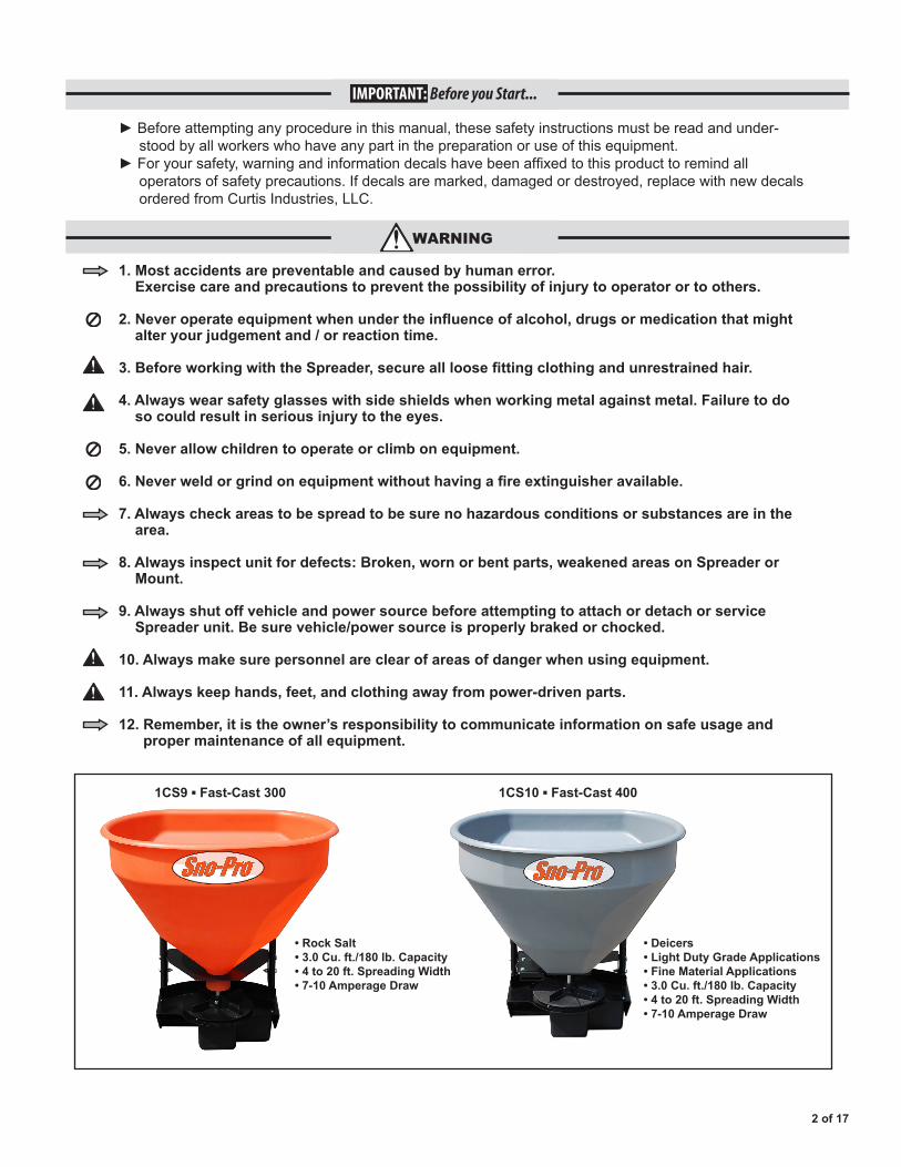
1CS9 ▪ Fast-Cast 300
• Rock Salt• 3.0 Cu. ft./180 lb. Capacity• 4 to 20 ft. Spreading Width• 7-10 Amperage Draw
• Deicers• Light Duty Grade Applications• Fine Material Applications• 3.0 Cu. ft./180 lb. Capacity• 4 to 20 ft. Spreading Width• 7-10 Amperage Draw
1CS10 ▪ Fast-Cast 400
3 of 17
■Neverexceed45m.p.h.whenloadedspreaderisattachedtovehicle.Brakingdistancesmaybe affectedandhandlingcharacteristicsmaybeimpairedatspeedsabove45m.p.h.
■Neverusewetmaterials,ormaterialswithforeigndebrisintheFast-CastSpreaders. Theseunitsaredesignedtohandledry,clean,free-flowingmaterial.
CurtisSpreaderscannotspreadwatersoftenersalt.
■NeverleavematerialinHopperforlongperiodsoftime.Beawarethatallicemeltersare hygroscopicandwillattractatmosphericmoistureandhardenup.
■Alwaysinspectpins,andlatcheswheneverattachingordetachingSpreader,andbeforetraveling.
■Inspecttheunitperiodicallyfordefects.Partsthatarebroken,missing,orwornoutmustbe replacedimmediately.Theunit,oranypartofitshouldnotbealteredwithoutpriorwritten permission from the manufacturer.
CAUTION
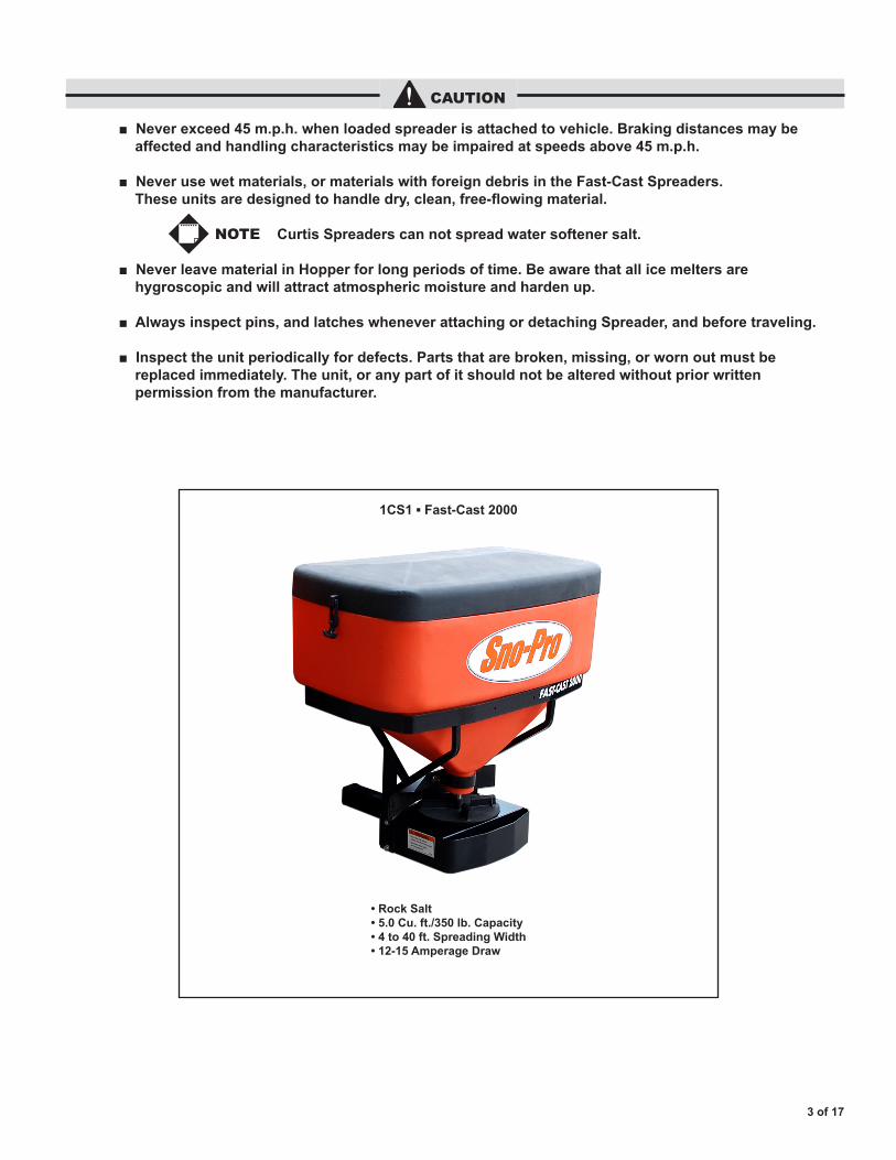
1CS1 ▪ Fast-Cast 2000
• Rock Salt• 5.0 Cu. ft./350 lb. Capacity• 4 to 40 ft. Spreading Width• 12-15 Amperage Draw
NOTE
1g.InstallignitionwiretoanauxiliarycircuitthatishotwhentheignitionkeyisturnedtoONposition.Thiswireis60"longandhasafemaleterminalattachedtoit.ThiswirewillplugintobackofController.ThiswiremustbeinstalledinorderforControllertooperate.
1h.PushtheON/OFFbuttonontheControllertocheckforpower,whenthathasbeenconfirmedturnpowerOFF.Theelectricalportionoftheinstallationiscomplete.
Ifaddinganinlinefuse, use a 35 amp slow blow fuse onFast-Cast2000only.
SECTION 2. OPERATING THE SPREADER
2a. PREPARATION Sweepareaclearofforeign objects or obstacles that could cause personal injury. Keepotherpersons,children, or animals out of the area to be spread.
2b. SPREADER LOADING
Do not overload vehicle. Rock Saltweighs35-40poundsper cubic foot. Maximumweightofmaterials fortheFast-Cast2000is 350lbs.forapickuptruck, and 250 lbs. for a UTV mounted Spreader.
Always comply with manufacturer’smaximum grossvehicleweightratings.
Never leave materials in Hopperforlongperiodsof timeassaltishygroscopic and will attract atmospheric moisture and harden up.
4 of 17
Sno-Pro Fast-Cast Series Spreaders
NOTE
CAUTION
CAUTION
WARNING
SECTION 1. SPREADER WIRING STEPS (Refer to Page 17)
1a. TheHarnessAssemblywillberoutedfromtherearofthevehicletothefront.RouteHarnessalongframeandattachtoframeholesandframesupports.
Itisnotrecommendedto attach to fuel or brake lines for obvious reasons.
Donotrouteclosetoexhaustsystemorengine,eventhoughCurtisuseshightemperaturewiring,thewiringcouldstillmeltunderextremeheatandshortthespreaderelectricalsystem,aswellasthevehicleelectricalsystem.
1b. MountRearPlugonbumperusingsuppliedbolts.Locatetowardsthecenterofthebumpertoreducetheamountofdebristhetireswillthrowtotherear.
Apply a small amount of dielectricgreasetotheplug.
1c. SecureHarnessfromthereartothefrontusingheavydutytie-wrapsorframeclipsalongtheframeandlighterdutytie-wrapsinallotherlocations.
1d. LayoutHarnessportionthatconnectstothebatteryalongthefirewallandfenderwell.DonotconnectpowerleadstoBatteryatthistime.Drilla3/4"holeinthefirewall,oruseexistingaccesshole,forthecontrolportionoftheHarnessandrouteconnectorandHarnessthroughhole.BesuretochecktheareaontheothersideofthefirewalltobecertainthatyouarenotgoingtodrillintothevehicleharnessoraControlModule.Generallyyoucandrilloneithersideofthesteeringwheelforagoodlocation.
1e. ConnectHarnesstothebackoftheControllerandmounttoasuitablelocation.
You may want to contact customerbeforemounting controller,someprefernotto have holes drilled into the dashboard.
Tie-wraplooseControllerHarnessandmovetothevehicleenginecompartment.
1f. Connectpowerleadstothe Battery:Red(+)Positive,Black(–)Negative.AlwaysconnecttotheprimaryBatteryifusingaDualBatterySystem.Securelooseloomtoanyotherlargeormediumvehicleharnesswithmediumdutytie-wraps;thiswillsecurewiringHarness.
WARNING
IMPORTANT
IMPORTANT
NOTE
Sno-Pro Fast-Cast Series Spreaders
5 of 17
2c. SPREADER LOADING TIPS
►Neverexceed10m.p.h.whenspreading.
►Forawiderpass,increaseSpinnerspeed.
►Foraheavierpass,driveslower.
►NeveroperateSpreadernearpedestrians.
►Spreadicemelterswiththestormtopreventunmanageablelevelsofice.
►Calculatespreadpatternwhennearvegetation.
2d. FAST-CAST 2000 OPERATION
(1.) TheVariableSpeedControllerhasfinger-tipdialaction.
(2.) ToStart,pressPowerSwitchonControllerandSpreaderwillacceleratetospeedsetondial.
(3.) ToStop,pressPowerSwitchonControllertooffposition.
(4.) AdjustspeedofSpinnerbyusingdialonrightsideofController.
SECTION 3. FAST-CAST 400 ASSEMBLY STEPS (Refer to Page 12)
3a. AttachHopperTubeSupport(17)toTransmissionWeldment(18)usingfour5/16"-18x1-3/4"HexBolts(11)andfour5/16"LockNuts(3)UsethefourbottommountingholesatendsofHopperTubeSupport(17).
3b. LocateSpreaderGateDeck(15)andplaceupsidedownonaflatworksurface.
3c. AssembleGateIndicator/Stop(12)onStopSlidewithGateKnob(7).GateIndicator/StopmustbeontheinsideofGateDeckwhereitwillstopthetrack.
3d. Insertone5/16"Boltwithhole(10)throughGateIndicator/Stop(12).Handtightenone5/16"LockNut(3)onBolt.
3e. LocateBulkheadCableFitting(9).ThreadontoT-HandleCable-20'(8)rubbercoating.
3f. InsertCableassemblythroughTabonGateDeck.SecurewithsuppliedWasherandNuts.
A Nut must be positioned on both sides of tab on Gate Deck.
3g.TurnoverGateDeckandlowertheassemblyovertheSpinnerShaft.TheSpinnerShaftmustbeinsertedthroughthe5/8"holeonGateDeck.
3h. FastenGateDecktoHopperTubeusingfour5/16"HexBolts(11)andfour5/16"LockNuts(3).
Firsttightenbottombolts, pullfrontofGateDeckup, thentightentopsetofbolts.
3i. PlaceHopper(16)onGateDeckandovertheSpinnerShaft.
3j. Handtightenthetwo5/16"x1"Bolts(5)insertedthroughbottomofHopper.
3k. PlaceoneFenderWasher(1)overeachofthefourHexBolts(11).InsertthefourBoltswithFenderWashersthroughHopperbackandthroughTubeSupport.Securewithfour5/16"Locknuts(3).
3l.FullytightenthetwoBoltsinbottomofHopperthatsecuretheHoppertotheDeckinstalledinStep3j.
RefertoPage13forthe followingSteps.
3m. PositionAgitator(11)onSpinnerShaft.Tightentomiddleofflatwithshortallenkey.
3n. AttachReceiverMount(18)toTransmissionWeldment(17)usingfour1/2"HexBolts(19)andfour1/2"LockNuts(20).
CABLE INSTALLATION STEPS
3o.MountSpreaderonvehicleinitspermanentlocation.InsertHitchPininhitchtopreventunitfrommoving.
3p. RouteT-Handletodesiredoperatinglocation.TherecannotbeanybendsorsharpcornersintheCable.
3q. TakeT-HandleoutofSleeve.TakeNutsandWasheroffSleeve.
3r. Drilla1/2"diameterholetomountT-Handle.ThreadonesuppliedNutandWasheronCableafterinsertingthroughdrilledhole.
3s. CompletelyclosetheGateSlide.
3t. Re-insertCableHandleandwireallthewayuntiltheHandleportionofT-HandleCable(8)contactsBulk-headCableFitting(9).AimthroughBoltwithhole(10)andtightenBolt.NOTE
NOTE
NOTE
6 of 17
Sno-Pro Fast-Cast Series Spreaders
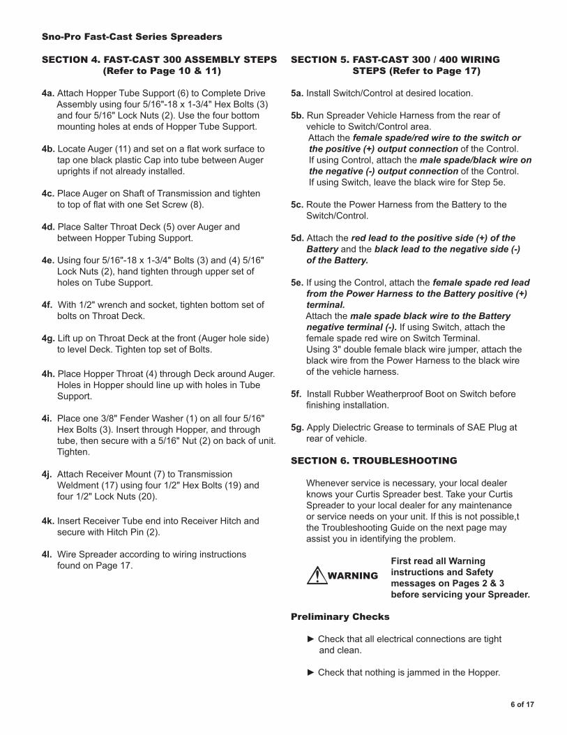
SECTION 4. FAST-CAST 300 ASSEMBLY STEPS (Refer to Page 10 & 11)
4a. AttachHopperTubeSupport(6)toCompleteDriveAssemblyusingfour5/16"-18x1-3/4"HexBolts(3)andfour5/16"LockNuts(2).UsethefourbottommountingholesatendsofHopperTubeSupport.
4b. LocateAuger(11)andsetonaflatworksurfacetotaponeblackplasticCapintotubebetweenAugeruprightsifnotalreadyinstalled.
4c. PlaceAugeronShaftofTransmissionandtightentotopofflatwithoneSetScrew(8).
4d. PlaceSalterThroatDeck(5)overAugerandbetweenHopperTubingSupport.
4e. Usingfour5/16"-18x1-3/4"Bolts(3)and(4)5/16"LockNuts(2),handtightenthroughuppersetofholesonTubeSupport.
4f. With1/2"wrenchandsocket,tightenbottomsetofboltsonThroatDeck.
4g.LiftuponThroatDeckatthefront(Augerholeside)tolevelDeck.TightentopsetofBolts.
4h. PlaceHopperThroat(4)throughDeckaroundAuger.HolesinHoppershouldlineupwithholesinTubeSupport.
4i. Placeone3/8"FenderWasher(1)onallfour5/16"HexBolts(3).InsertthroughHopper,andthroughtube,thensecurewitha5/16"Nut(2)onbackofunit.Tighten.
4j. AttachReceiverMount(7)toTransmissionWeldment(17)usingfour1/2"HexBolts(19)andfour1/2"LockNuts(20).
4k. InsertReceiverTubeendintoReceiverHitchandsecurewithHitchPin(2).
4l. WireSpreaderaccordingtowiringinstructionsfoundonPage17.
SECTION 5. FAST-CAST 300 / 400 WIRING STEPS (Refer to Page 17)
5a. InstallSwitch/Controlatdesiredlocation.
5b. RunSpreaderVehicleHarnessfromtherearofvehicletoSwitch/Controlarea.Attachthefemale spade/red wire to the switch or the positive (+) output connectionoftheControl.IfusingControl,attachthemale spade/black wire on the negative (-) output connectionoftheControl.IfusingSwitch,leavetheblackwireforStep5e.
5c. RoutethePowerHarnessfromtheBatterytotheSwitch/Control.
5d. Attachthered lead to the positive side (+) of the Batteryandtheblack lead to the negative side (-) of the Battery.
5e. IfusingtheControl,attachthefemale spade red lead from the Power Harness to the Battery positive (+) terminal.Attachthemale spade black wire to the Battery negative terminal (-).IfusingSwitch,attachthefemalespaderedwireonSwitchTerminal.Using3"doublefemaleblackwirejumper,attachtheblackwirefromthePowerHarnesstotheblackwireofthevehicleharness.
5f. InstallRubberWeatherproofBootonSwitchbeforefinishinginstallation.
5g.ApplyDielectricGreasetoterminalsofSAEPlugatrearofvehicle.
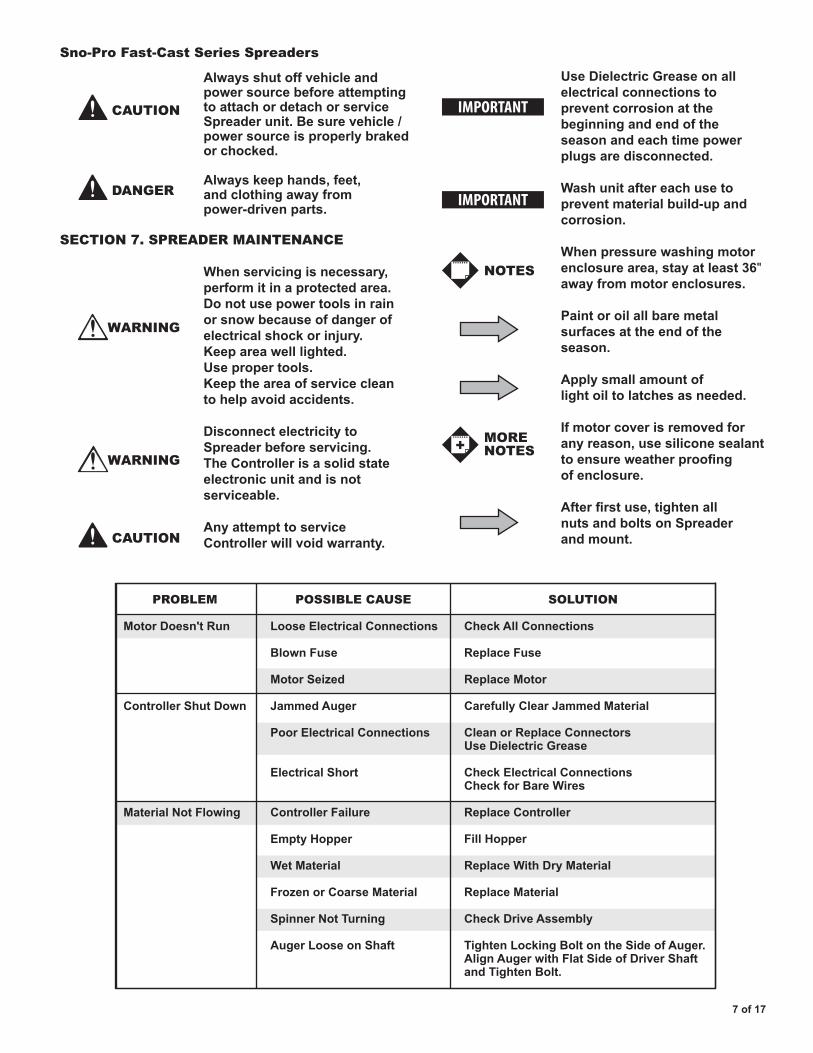
SECTION 6. TROUBLESHOOTING
Wheneverserviceisnecessary,yourlocaldealerknowsyourCurtisSpreaderbest.TakeyourCurtisSpreadertoyourlocaldealerforanymaintenanceorserviceneedsonyourunit.Ifthisisnotpossible,ttheTroubleshootingGuideonthenextpagemayassistyouinidentifyingtheproblem.
FirstreadallWarning instructionsandSafety messagesonPages2&3 beforeservicingyourSpreader.
Preliminary Checks
►Checkthatallelectricalconnectionsaretightandclean.
►CheckthatnothingisjammedintheHopper.
WARNING
Use Dielectric Grease on all electrical connections to prevent corrosion at the beginningandendofthe season and each time power plugsaredisconnected.
Washunitaftereachuseto preventmaterialbuild-upand corrosion.
Whenpressurewashingmotor enclosurearea,stayatleast36" away from motor enclosures.
Paintoroilallbaremetal surfaces at the end of the season.
Apply small amount of lightoiltolatchesasneeded.
Ifmotorcoverisremovedfor anyreason,usesiliconesealant toensureweatherproofing of enclosure.
Afterfirstuse,tightenall nutsandboltsonSpreader and mount.
Sno-Pro Fast-Cast Series Spreaders
7 of 17
Always shut off vehicle and powersourcebeforeattempting to attach or detach or service Spreaderunit.Besurevehicle/ power source is properly braked or chocked.
Alwayskeephands,feet, andclothingawayfrom power-drivenparts.
SECTION 7. SPREADER MAINTENANCE
Whenservicingisnecessary, perform it in a protected area. Do not use power tools in rain orsnowbecauseofdangerof electrical shock or injury. Keepareawelllighted. Use proper tools. Keep the area of service clean to help avoid accidents.
Disconnect electricity to Spreaderbeforeservicing. TheControllerisasolidstate electronic unit and is not serviceable.
Any attempt to service Controllerwillvoidwarranty.
CAUTION
DANGER
WARNING
IMPORTANT
WARNING
CAUTION
IMPORTANT
NOTES
MORENOTES
PROBLEM POSSIBLE CAUSE SOLUTION
Motor Doesn't Run
Controller Shut Down
Material Not Flowing
Loose Electrical Connections
Blown Fuse
Motor Seized
Jammed Auger
Poor Electrical Connections
Electrical Short
Controller Failure
Empty Hopper
Wet Material
Frozen or Coarse Material
Spinner Not Turning
Auger Loose on Shaft
Check All Connections
Replace Fuse
Replace Motor
Carefully Clear Jammed Material
Clean or Replace ConnectorsUse Dielectric Grease
Check Electrical ConnectionsCheck for Bare Wires
Replace Controller
Fill Hopper
Replace With Dry Material
Replace Material
Check Drive Assembly
Tighten Locking Bolt on the Side of Auger.Align Auger with Flat Side of Driver Shaftand Tighten Bolt.
8 of 17
Sno-Pro Fast-Cast Series Spreaders
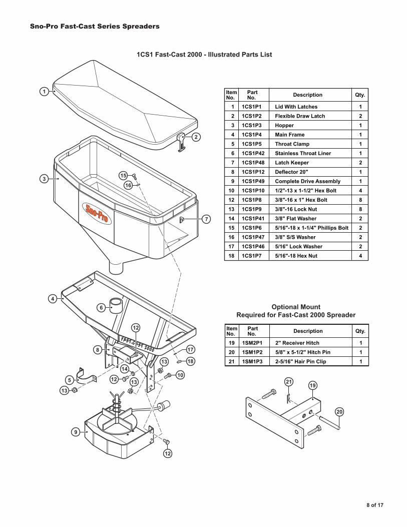
1CS1 Fast-Cast 2000 - Illustrated Parts List
®™
13
12
12
14
7
15
16
18
17
1013
13
20
2119
19
20
21
1SM2P1
1SM1P2
1SM1P3
2" Receiver Hitch
5/8" x 5-1/2" Hitch Pin
2-5/16" Hair Pin Clip
ItemNo.
1
1
1
Qty.PartNo. Description
Optional MountRequired for Fast-Cast 2000 Spreader
1
2
3
4
5
6
7
8
9
10
12
13
14
15
16
17
18
1CS1P1
1CS1P2
1CS1P3
1CS1P4
1CS1P5
1CS1P42
1CS1P48
1CS1P12
1CS1P49
1CS1P10
1CS1P8
1CS1P9
1CS1P41
1CS1P6
1CS1P47
1CS1P46
1CS1P7
Lid With Latches
Flexible Draw Latch
Hopper
Main Frame
Throat Clamp
Stainless Throat Liner
Latch Keeper
Deflector 20"
Complete Drive Assembly
1/2"-13 x 1-1/2" Hex Bolt
3/8"-16 x 1" Hex Bolt
3/8"-16 Lock Nut
3/8" Flat Washer
5/16"-18 x 1-1/4" Phillips Bolt
3/8" S/S Washer
5/16" Lock Washer
5/16"-18 Hex Nut
ItemNo.
1
2
1
1
1
1
2
1
1
4
8
8
2
2
2
2
4
Qty.PartNo. Description
3
1
46
8
9
5
2
FAST-CAST 2000
12

Sno-Pro Fast-Cast Series Spreaders
9 of 17
6
4
2
7
5
8
9 Retaining Pin
11
17
14
15
10
131612
3
1
1CS1 Fast-Cast 2000 Complete Drive Assembly - Illustrated Parts List
1
2
3
4
5
6
7
8
1CS1P16
1CS1P53
1CS1P17
1CS1P13
1CS1P21
1CS1P19
1CS1P22
1CS1P29
Motor 12 Volt DC
Transmission
Motor Cover
Drive Enclosure
Fast-Cast 2000 Power Cable
Auger
Cord Restraint
3/16" Aluminum Rivet
ItemNo.
1
1
1
1
1
1
1
6
Qty.PartNo. Description
9
10
11
12
13
14
15
16
17
1CS1P25
1CS1P24
1CS1P30
1CS1P27
1CS1P28
1CS1P23
1CS1P18A
1CS1P51
CS1P18
1/4"-20 x 3/4" Hex Bolt
5/16"-18 x 1/2" Hex Bolt
1/4" Lock Washer
#10-32 x 5/8" Cap Screw
#10 Lock Washer
5/16"-18 x 3/8" Set Screw
10" Steel Spinner (Optional)
Motor Drive Coupler
10" Plastic Spinner withRetaining Pin (Standard)
ItemNo.
4
1
4
2
2
1
1
1
1
Qty.PartNo. Description
OPTIONAL STEEL SPINNER

Sno-Pro Fast-Cast Series Spreaders
10 of 17
1CS9 Fast-Cast 300 - Illustrated Parts List
1
2
3
4
5
6
7
1CS2P15
1SM5P1
D6462
1CS9P1
1CS9P2
1CS9P3
D6485
3/8" Fender Washer
5/16"-18 Lock Nut
5/16"-18 x 1-3/4" HHCS
Fast-Cast 300 Salt Hopper
Salter Throat Deck
Hopper Tube Support
Light Duty Receiver Mount
ItemNo.
4
12
12
1
1
1
1
Qty.PartNo. Description
3
3
2
2
2
6
3
7
13
4
5
Sno-Pro Fast-Cast Series Spreaders
11 of 17
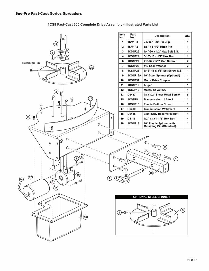
1CS9 Fast-Cast 300 Complete Drive Assembly - Illustrated Parts List
2
67
11
8
3
13
19
1
18
10
16
15
20
12
17
1
2
3
4
6
7
8
9
10
11
12
13
15
16
17
18
19
20
1SM1P3
1SM1P2
1CS1P25
1CS1P24
1CS1P27
1CS1P28
1CS1P23
1CS1P18A
1CS1P51
1CS1P19
1CS2P10
D6487
1CS9P5
1CS9P16
D6480
D6485
D4116
1CS1P18
2-5/16" Hair Pin Clip
5/8" x 5-1/2" Hitch Pin
1/4"-20 x 1/2" Hex Bolt S.S.
5/16"-18 x 1/2" Hex Bolt
#10-32 x 5/8" Cap Screw
#10 Lock Washer
5/16"-18 x 3/8" Set Screw S.S.
10" Steel Spinner (Optional)
Motor Drive Coupler
Auger
Motor, 12 Volt DC
#8 x 1/2" Sheet Metal Screw
Transmission 14.5 to 1
Plastic Bottom Cover
Transmission Weldment
Light Duty Receiver Mount
1/2"-13 x 1-1/2" Hex Bolt
10" Plastic Spinner with
ItemNo.
1
1
4
1
2
2
1
1
1
1
1
5
1
1
1
1
4
1
Qty.PartNo. Description
Retaining Pin (Standard)
49
OPTIONAL STEEL SPINNER
Retaining Pin

Sno-Pro Fast-Cast Series Spreaders
12 of 17
1CS10 Fast-Cast 400 Spreader - Illustrated Parts List
1
2
3
4
5
6
7
8
9
10
1CS2P15
1CS1P24
1SM5P1
1CS1P46
-
1CS1P7
1CS10P6
1GC1A
1CS2P16
1CS2P17
3/8" Fender Washer
5/16"-18 x 1/2" Hex Bolt
5/16"-18 Lock Nut
5/16" Lock Washer
5/16"-18 x 1" Hex Bolt
5/16"-18 x 1" Hex Nut
Gate Knob
T-Handle Cable - 20'
Bulkhead Cable Fitting
5/16"-18 x 3/4" Bolt w/hole
ItemNo.
4
2
14
1
2
1
1
1
1
1
Qty.PartNo. Description
11
12
13
14
15
16
17
18
19
20
D6462
1CS10P5
1CS10P4
1CS10P3
1CS10P2
1CS10P1
1CS9P3
D6480
D6485
D4116
5/16"-18 x 1-3/4" HHCS
Gate Indicator / Stop
Fast-Cast 400 Gate Track
Fast-Cast 400 Gate Slide
Fast-Cast 400 Gate Deck
Fast-Cast 400 Hopper
Hopper Tube Support
Transmission Weldment
Light Duty Receiver Mount
1/2"-13 x 1-1/2" Hex Bolt
ItemNo.
12
1
1
1
1
1
1
1
1
4
Qty.PartNo. Description
11
11
11
3
3
3
1
11
16
15
19
17
18
2
55
2
2
6
89
7
13
1014
15 Gate Deck Underside View
Sno-Pro Fast-Cast Series Spreaders
13 of 17
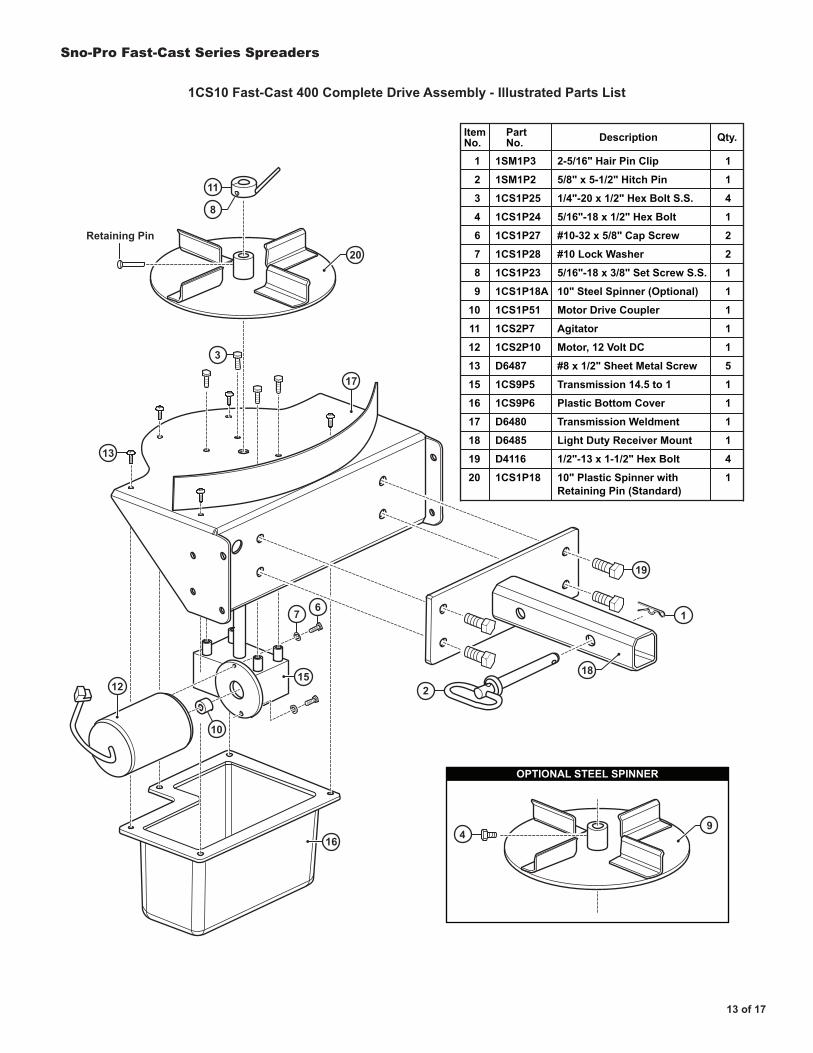
1CS10 Fast-Cast 400 Complete Drive Assembly - Illustrated Parts List
2
67
11
8
3
13
19
1
18
10
16
15
20
12
1
2
3
4
6
7
8
9
10
11
12
13
15
16
17
18
19
20
1SM1P3
1SM1P2
1CS1P25
1CS1P24
1CS1P27
1CS1P28
1CS1P23
1CS1P18A
1CS1P51
1CS2P7
1CS2P10
D6487
1CS9P5
1CS9P6
D6480
D6485
D4116
1CS1P18
2-5/16" Hair Pin Clip
5/8" x 5-1/2" Hitch Pin
1/4"-20 x 1/2" Hex Bolt S.S.
5/16"-18 x 1/2" Hex Bolt
#10-32 x 5/8" Cap Screw
#10 Lock Washer
5/16"-18 x 3/8" Set Screw S.S.
10" Steel Spinner (Optional)
Motor Drive Coupler
Agitator
Motor, 12 Volt DC
#8 x 1/2" Sheet Metal Screw
Transmission 14.5 to 1
Plastic Bottom Cover
Transmission Weldment
Light Duty Receiver Mount
1/2"-13 x 1-1/2" Hex Bolt
10" Plastic Spinner withRetaining Pin (Standard)
ItemNo.
1
1
4
1
2
2
1
1
1
1
1
5
1
1
1
1
4
1
Qty.PartNo. Description
17
49
OPTIONAL STEEL SPINNER
Retaining Pin
14 of 17
Sno-Pro Fast-Cast Series Spreaders
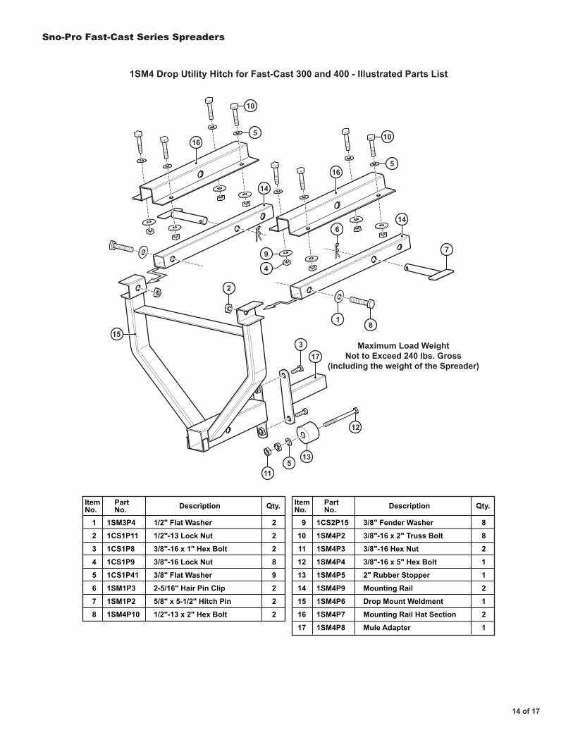
1SM4 Drop Utility Hitch for Fast-Cast 300 and 400 - Illustrated Parts List
153
7
614
14
10
5
10
5
9
4
2
81
115
13
12
17
16
16
Maximum Load WeightNot to Exceed 240 lbs. Gross
(including the weight of the Spreader)
1
2
3
4
5
6
7
8
1SM3P4
1CS1P11
1CS1P8
1CS1P9
1CS1P41
1SM1P3
1SM1P2
1SM4P10
1/2" Flat Washer
1/2"-13 Lock Nut
3/8"-16 x 1" Hex Bolt
3/8"-16 Lock Nut
3/8" Flat Washer
2-5/16" Hair Pin Clip
5/8" x 5-1/2" Hitch Pin
1/2"-13 x 2" Hex Bolt
ItemNo.
2
2
2
8
9
2
2
2
Qty.PartNo. Description
9
10
11
12
13
14
15
16
17
1CS2P15
1SM4P2
1SM4P3
1SM4P4
1SM4P5
1SM4P9
1SM4P6
1SM4P7
1SM4P8
3/8" Fender Washer
3/8"-16 x 2" Truss Bolt
3/8"-16 Hex Nut
3/8"-16 x 5" Hex Bolt
2" Rubber Stopper
Mounting Rail
Drop Mount Weldment
Mounting Rail Hat Section
Mule Adapter
ItemNo.
8
8
2
1
1
2
1
2
1
Qty.PartNo. Description
15 of 17
Sno-Pro Fast-Cast Series Spreaders
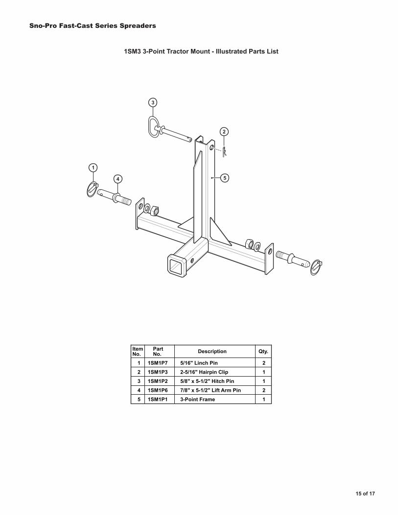
1SM3 3-Point Tractor Mount - Illustrated Parts List
1
2
3
4
5
1SM1P7
1SM1P3
1SM1P2
1SM1P6
1SM1P1
5/16" Linch Pin
2-5/16" Hairpin Clip
5/8" x 5-1/2" Hitch Pin
7/8" x 5-1/2" Lift Arm Pin
3-Point Frame
ItemNo.
2
1
1
2
1
Qty.PartNo. Description
5
3
2
1
4
16 of 17
Sno-Pro Fast-Cast Series Spreaders
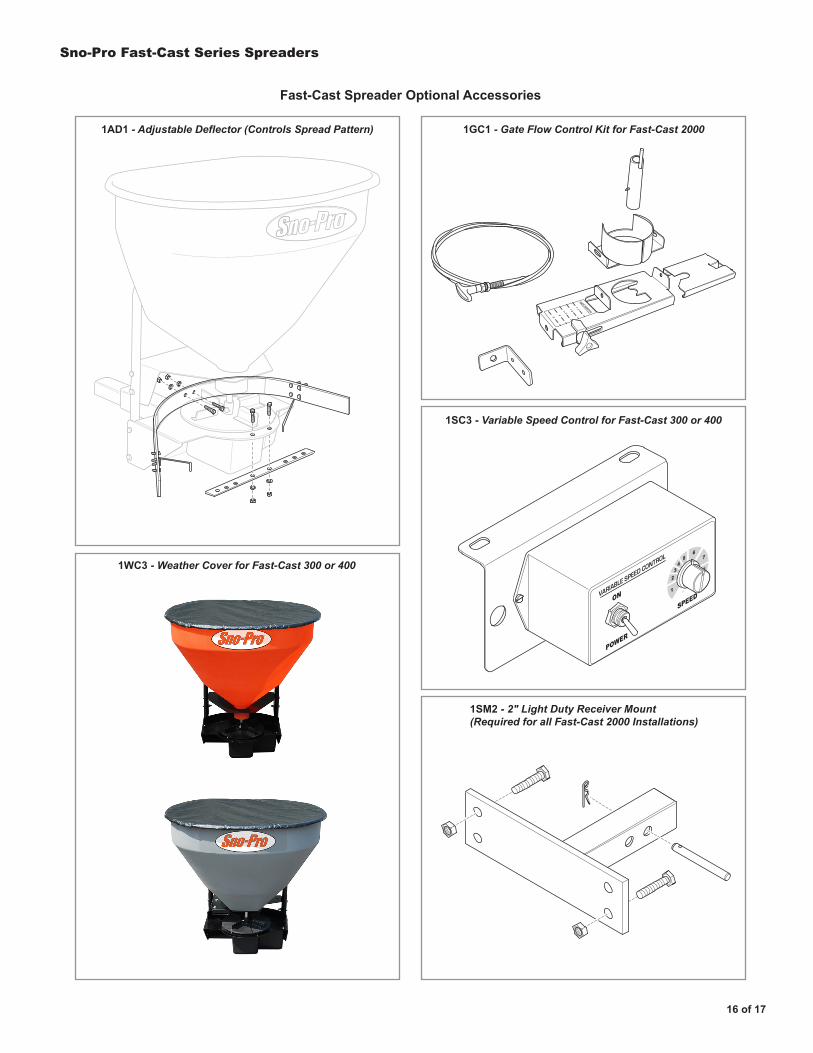
1AD1 - Adjustable Deflector (Controls Spread Pattern) 1GC1 - Gate Flow Control Kit for Fast-Cast 2000
1SC3 - Variable Speed Control for Fast-Cast 300 or 400
1SM2 - 2" Light Duty Receiver Mount(Required for all Fast-Cast 2000 Installations)
1WC3 - Weather Cover for Fast-Cast 300 or 400
ON
POWER
SPEEDVARIABLE SPEED CONTROL
34
56
7
84
42
1
GATE POSITION
12345
Fast-Cast Spreader Optional Accessories
Sno-Pro Fast-Cast Series Spreaders
17 of 17
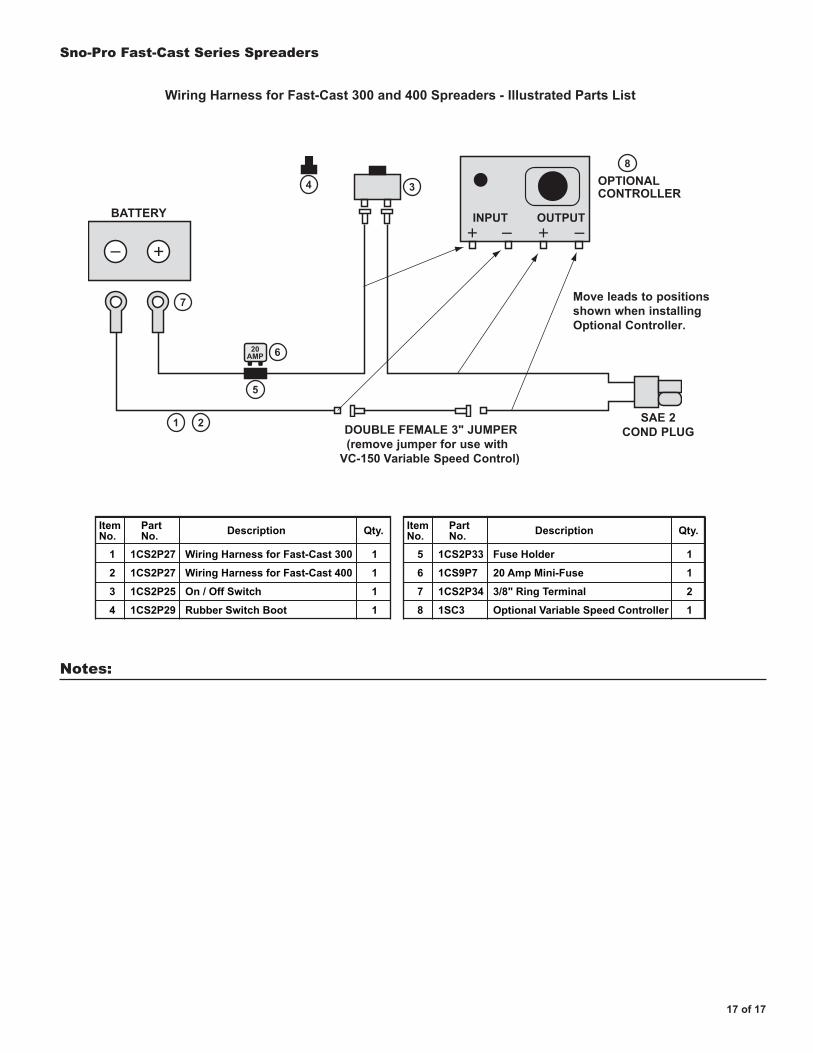
20AMP
INPUT OUTPUTBATTERY
OPTIONAL CONTROLLER
Move leads to positions shown when installing Optional Controller.
SAE 2COND PLUGDOUBLE FEMALE 3" JUMPER
(remove jumper for use with VC-150 Variable Speed Control)
4
6
5
1 2
7
3
8
1
2
3
4
1CS2P27
1CS2P27
1CS2P25
1CS2P29
Wiring Harness for Fast-Cast 300
Wiring Harness for Fast-Cast 400
On / Off Switch
Rubber Switch Boot
ItemNo.
1
1
1
1
Qty.PartNo. Description
5
6
7
8
1CS2P33
1CS9P7
1CS2P34
1SC3
Fuse Holder
20 Amp Mini-Fuse
3/8" Ring Terminal
Optional Variable Speed Controller
ItemNo.
1
1
2
1
Qty.PartNo. Description
Wiring Harness for Fast-Cast 300 and 400 Spreaders - Illustrated Parts List
Notes: