fast garbling of circuits under standard assumptions
TRANSCRIPT

Fast Garbling of Circuits Under Standard Assumptions∗
Shay Gueron† Yehuda Lindell‡ Ariel Nof† Benny Pinkas†
June 13, 2017
Abstract
Protocols for secure computation enable mutually distrustful parties to jointly compute ontheir private inputs without revealing anything but the result. Over recent years, secure com-putation has become practical and considerable effort has been made to make it more and moreefficient. A highly important tool in the design of two-party protocols is Yao’s garbled circuitconstruction (Yao 1986), and multiple optimizations on this primitive have led to performanceimprovements of orders of magnitude over the last years. However, many of these improvementscome at the price of making very strong assumptions on the underlying cryptographic primitivesbeing used (e.g., that AES is secure for related keys, that it is circular secure, and even thatit behaves like a random permutation when keyed with a public fixed key). The justificationbehind making these strong assumptions has been that otherwise it is not possible to achievefast garbling and thus fast secure computation. In this paper, we take a step back and examinewhether it is really the case that such strong assumptions are needed. We provide new methodsfor garbling that are secure solely under the assumption that the primitive used (e.g., AES) isa pseudorandom function. Our results show that in many cases, the penalty incurred is notsignificant, and so a more conservative approach to the assumptions being used can be adopted.
1 Introduction
1.1 Background
In the setting of secure computation, a set of parties with private inputs wish to compute a jointfunction of their inputs, without revealing anything but the output. Protocols for secure compu-tation guarantee privacy (meaning that the protocol reveals nothing but the output), correctness(meaning that the correct function is computed), and independence of inputs (meaning that partiesare not able to make their inputs depend on the other parties’ inputs). These security guaranteesare to be provided in the presence of adversarial behavior. There are two classic adversary modelsthat are typically considered: semi-honest (where the adversary follows the protocol specificationbut may try to learn more than is allowed from the protocol transcript) and malicious (where theadversary can run any arbitrary polynomial-time strategy in its attempt to breach security).
∗An extended abstract of this paper appeared at ACM CCS 2015.†University of Haifa and Intel Haifa, Israel. email: [email protected]. Supported by the PQCRYPTO
project, which was partially funded by the European Commission Horizon 2020 research Programme, grant #645622.‡Bar-Ilan University, Israel. email: [email protected], [email protected], [email protected]. Supported
by the European Research Council under the ERC consolidators grant agreement n. 615172 (HIPS) and under theEuropean Union’s Seventh Framework Program (FP7/2007-2013) grant agreement n. 609611 (PRACTICE), and bythe BIU Center for Research in Applied Cryptography and Cyber Security in conjunction with the Israel NationalCyber Bureau in the Prime Minister’s Office.
1

Garbled circuits. One of the central tools in the construction of secure two-party protocolsis Yao’s garbled circuit [18, 22]. The basic idea behind Yao’s protocol is to provide a method ofcomputing a circuit so that values obtained on all wires other than circuit-output wires are neverrevealed. For every wire in the circuit, two random or garbled values are specified such that onevalue represents 0 and the other represents 1. For example, let i be the label of some wire. Then,two values k0
i and k1i are chosen, where kbi represents the bit b. An important observation here is
that even if one of the parties knows the value kbi obtained by the wire i, this does not help it todetermine whether b = 0 or b = 1 (because both k0
i and k1i are identically distributed). Of course,
the difficulty with such an idea is that it seems to make computation of the circuit impossible.That is, let g be a gate with incoming wires i and j and output wire `. Then, given two randomvalues kbi and kcj , it does not seem possible to compute the gate because b and c are unknown. Wetherefore need a method of computing the value of the output wire of a gate (also a random valuek0` or k1
` ) given the value of the two input wires to that gate.In short, this method involves providing “garbled computation tables” that map the random
input values to random output values. However, this mapping should have the property that giventwo input values, it is only possible to learn the output value that corresponds to the output ofthe gate (the other output value must be kept secret). This is accomplished by viewing the fourpossible inputs to the gate, k0
i , k1i , k
0j , and k1
j , as encryption keys. Then, the output values k0` and
k1` , which are also keys, are encrypted under the appropriate keys from the incoming wires. For
example, let g be an OR gate. Then, the key k1` is encrypted under the pairs of keys associated
with the input values (1, 1), (1, 0) and (0, 1). In contrast, the key k0` is encrypted under the pair of
keys associated with (0, 0).
Fast garbling and assumptions. Today, secure computation is fast enough to solve numerousproblems in practice. This has been achieved due to multiple significant efficiency improvementsthat have been made on the protocol level, and also due to garbled circuits themselves. Many ofthe optimizations to garbled circuits – described below – come at the price of assuming strongassumptions on the security of the cryptographic primitives being used. For example, the free-XOR technique requires assuming circular security as well as a type of correlation robustness [7],the use of fixed-key AES requires assuming that AES with a fixed key behaves like a public randompermutation [5], reductions in the number of encryption operations from 2 to 1 per entry in thegarbled gate requires correlation robustness (when a hash function is used) and a related-keyassumption (when AES is used).
Typically, the use of less standard cryptographic assumptions is accepted where necessary, es-pecially in areas like secure computation where the costs are in general very high. However, inpractice, solid cryptographic engineering practices dictate a more conservative approach to as-sumptions. New types of elliptic curve groups are not adopted quickly, people shy away fromnon-standard use of block ciphers, and more. This is based on sound principles, and on the under-standing that deployed solutions are very hard to change if vulnerabilities are discovered. In thefield of secure computation, the willingness to take any assumption that enables a faster implemen-tation stands in stark contrast to standard cryptographic practice. In this paper, we propose topause, take a step back, and ask the question how much do non-standard assumptions really costus and are they justified. We remark, for just one example, that practitioners have warned againstassuming that AES is an ideal cipher, due to related key weaknesses that have been found; seee.g., [4,6]. Furthermore, the security of AES with a known key was studied in [13], and the results
2

show that the security margin for using AES in this way is arguably not as high as we would like.In particular, [13] present an algorithm that distinguishes 7-round AES with a fixed key from apublic random permutation, in time 256 and little memory. As in most situations, if the benefitis huge, then more flexibility with respect to the assumptions is justified, whereas if the gains aresmaller then a more cautious approach is taken.
The focus of this paper is to study how much is really gained by relying on non-standardassumptions and to provide optimizations that require assuming nothing more than that AESbehaves like a pseudorandom function.
1.2 Known Garbled Circuit Optimizations
Before proceeding to describe our work, we present an overview of the most important efficiencyimprovements to garbled circuits:
• Point and permute [20]: In order to prevent the garbled circuit evaluator from knowingwhat it is evaluating, the original construction randomly permuted the ciphertexts in eachgarbled gate. Then, when computing the garbled circuit, the evaluator tries each ciphertextin the gate until one correctly decrypts (this requires an additional mechanism to ensurethat only one ciphertext decrypts to a valid value). On average, this means that 2.5 entriesneed to be decrypted per gate (where each costs 2 decryptions). The point and permutemethod assigns a random permutation or signal bit to each wire, that determines the order ofthe garbled gate. Then, the encryption of a garbled value includes the bit needed to enabledirect access to the appropriate entry in the garbled table (given two garbled values and thetwo associated bits). This reduces the number of entries to decrypt to 1 (and thus 2 actualdecryptions).
• Free XOR [15]: The garbled circuit construction involves carrying out encryptions at everygate in the circuit, and storing 4 ciphertexts. The free-XOR method enables the computationof XOR gates for free (the computation requires only computing 1-2 XORs, and no ciphertextsneed be stored). This is achieved by choosing a fixed random mask ∆ and making the garbledvalues on every wire have fixed difference ∆ (i.e., for every i, the garbled values are k0
i andk1i = k0
i⊕∆, where k0i is random). In many circuits, the number of XOR gates is very large and
so this significantly reduces the cost (e.g., in the AES circuit there are approximately 7,000AND gates and 25,000 XOR gates; in a 32x32 bit multiplier circuit there are approximately6,000 AND gates and 1,000 XOR gates [1]).
We remark that the free-XOR method is patented, and as such, its use is restricted [16].
• Reductions in garbled-circuit size [14,20,21,23]: Historically, the most expensive partof any secure protocol was the cryptographic operations. However, significant algorithmicimprovements to secure protocols together with much faster implementations of cryptographicprimitives (e.g., due to better hardware) have considerably changed the equation. In manycases, communication can be the bottleneck and thus reducing the size of the garbled circuitis of great importance. In [20], a method for reducing the number of garbled entries in atable from 4 to 3 was introduced; this is referred to as 4-to-3 garbled row reduction (or 4-3GRR). This improvement is achieved by “forcing” the first ciphertext to be 0 (by settingthe appropriate garbled value on the output wire so that the ciphertext becomes 0). In [21],
3

polynomial interpolation was used to further reduce the number of ciphertexts to just 2; thisis referred to as 4-to-2 garbled row reduction (or 4-2 GRR).
Importantly, 4-3 GRR is compatible with free-XOR since only one output garbled value needsto taken as a function of the input values (and the other garbled value can be set accordingto the fixed ∆). In contrast, 4-2 GRR is not compatible with free XOR. In a work calledFlexOR [14], it was shown that in some cases, it is possible to use a combination of 4-2 GRRand 4-3 GRR together with free-XOR, and obtain an overall cost that is less than 4-3 GRRalone.
The state-of-the-art today is a new method called half gates [23], which reduces the numberof ciphertexts in AND gates from 4 to 2, while maintaining compatibility with free XOR (infact, half gates only work with free XOR).
• Number of encryptions [19]: Classically, each entry in a garbled gate contains the encryp-tion of one of the output garbled values under two input garbled values, and thus requirestwo encryptions. In [19], it was proposed to use a hash function as a type of key-derivationfunction, and to encrypt by hashing both input garbled values together and XORing theresult with the output garbled value. This is secure in the random-oracle model, or undera “correlation-robustness” assumption [12]. This reduces the number of operations from 2to 1. (Note however that two AES operations are typically much faster than a single hashoperation, especially when utilizing the AES-NI instruction.)
• Fixed-key AES and use of AES-NI [5]: AES-NI is a set of CPU instructions that are nowpart of the Intel architecture. They allow AES computations to be carried out at incrediblyfast rates, especially in modes of operation that can be highly pipelined. AES-NI offersinstructions for encryption/decryption and for the AES key expansion.
However, since typical AES usages encrypt multiple blocks with a single key, the key expan-sion instructions do not highly optimize this part of the processing, and the key schedulegeneration routine is relatively expensive (compared to encryption/decryption). More im-portantly, pipelining cannot be carried out between different keys. When computing garbledcircuits, 4 different keys are used in every gate, requiring many key schedules to be computedand preventing the use of pipelining.
In light of this, [5] proposed a method of using AES that is secure in the public randompermutation model. The method uses a fixed key for AES, applies AES on a combination ofthe input garbled values, and XORs the result with appropriate output garbled value. Thisreduces the number of AES computation to 4 per gate. Furthermore, since a fixed key is used,only one key schedule needs to be computed for the entire circuit, and the encryptions withina gate can be fully pipelined. This led to an extraordinary speedup in the computation ofgarbled circuits, as demonstrated in the JustGarble implementation [5].
We stress that there have been a very large number of works that have provided highly signifi-cant efficiency improvements to protocols that use garbled circuits. However, our focus here is onimprovements to garbled circuits themselves.
4

1.3 Our Results
We construct fast garbling methods solely under the assumption that AES behaves like a pseudo-random function. In particular, we do not use fixed-key AES, and we require two AES encryptionsfor generating each ciphertext in the garbled gates (since known techniques using just one encryp-tion require some sort of related-key security assumption). In addition, we do not use free-XOR(since this requires circularity). However, this does enable us to use 4-to-2 row reduction. In brief,we construct the following:
• Fast AES-NI without fixing the key: We show that, in addition to pipelining encryptions,it is also possible to pipeline the key schedule of AES-NI, in order to achieve very fast garblingtimes without using fixed-key AES or any other non-standard AES variant. Namely, the keyschedule processing of different keys can be pipelined together, so that the amortized effect ofkey scheduling on Yao garbling is greatly reduced. Our experiments (described below) showthat this and other optimizations of AES operations have become so fast that the benefits ofusing fixed-key AES are almost insignificant. Thus, in contrast to current popular belief, inmost cases fixed-key AES is not necessary for achieving extremely fast garbling.
• Low-communication XOR gates: Over the past years, it has become apparent that insecure protocols, communication is far more problematic than computation. The free-XORtechnique is so attractive exactly because it requires no computation but also no communica-tion for XOR gates. We provide a new garbling method for XOR gates that requires storingonly a single ciphertext per XOR gate; our technique is inspired by the work of [14]. Thecomputational cost is 3 AES computations for garbling the gate, and 1-2 AES computationsfor evaluating it. (This overhead is for an optimized garbling method that we show. We firstpresent a basic scheme requiring 4 AES computations for garbling and 2 computations forevaluation.)
• Fast 4-2 row reduction: As we have mentioned, once we no longer use the free-XOR tech-nique, we are able to use 4-2 GRR on the non-XOR gates. However, the method of [21] thatuses polynomial interpolation is rather complex to implement (requiring finite field operationsand precomputation of special constants to make it fast). In addition, even working in GF (2n)Galois fields and using the PCLMULQDQ Intel instruction, the cost is still approximatelyhalf an AES computation. We present a new method for 4-2 row reduction that uses a fewXOR operations only, and is trivial to implement.
Table 1 show the communication cost which our technique incurs, compared to the other opti-mizations mentioned before, with an emphasis on the security assumption each technique is basedupon.
We implemented these optimizations and compared them to JustGarble [5]. There is no doubtthat the cost of garbling and evaluation is higher using our method, since we have to run AESkey schedules, and we pay for computing XOR gates. However, we show that within protocolexecutions, the difference is insignificant. We demonstrate this running Yao’s protocol for semi-honest adversaries which consists of oblivious transfer (for which we use the fast OT extensionsof [2]), garbled-circuit evaluation and computation, and communication.1
1We do not count the base OTs of the OT extension since these would outweigh everything else, and can anywaybe precomputed. Our aim here is to see the effect of the change in the garbled circuits and our tests are under optimal
5

MethodSize of Garbled Table
AssumptionXOR AND
Naive 4 4 standard
4-3 GRR [20] 3 3 standard
4-2 GRR [21] 2 2 standard
This work 1 2 standard
This work 0-2 2 related-key
fleXOR [14] 0-2 2-3 circularity/related-key
free-XOR [15] 0 3 circularity
Half-Gates [23] 0 2 circularity
Table 1: Summary of garbled circuit’s size optimizations compared to our scheme
Experimental results. We ran Yao’s protocol for semi-honest adversaries inside Amazon EC2.The details of the results can be found in Section 6. The results show removing the public randompermutation assumption does not noticeably affect the performance of the protocol. Furthermore,in many scenarios, such as small circuits, large inputs, or relatively slow communication channels,garbling under the most conservative assumption (the existence of PRFs) performs on par with themost efficient garbling methods.
Patent-free garbled circuits. Another considerable advantage of using our method for com-puting XOR gates with low communication is that it does not rely on the free XOR techniqueand thus is not patented. Since patents in cryptography are typically an obstacle to adoption, webelieve that the search for efficient garbling techniques that are not patented is of great importance.
Garbling under weaker yet non-standard assumption. Our work focuses on the comparisonbetween garbling under a variety of strong assumptions (i.e., circularity, public random permuta-tion) and garbling under a standard pseudorandom function assumption only. However, there arealso garbling schemes that have been proven secure under a related-key assumption, but withoutcircularity [14]. In order to provide a more complete picture regarding the trade-off between ef-ficiency and security, we continue the directions introduced by [14] in Section 5. We present twonew heuristics for solving the algorithmic problem presented in [14], and show that a related-keyassumption based garbling scheme (using any of the suggested heuristics) improves garbling andcomputation time, but fails to significantly reduce the communication overhead of the protocol.
conditions for JustGarble-type constructions [5]. For the same reason, we do not look at the effect inside protocolsfor malicious adversaries since all of the other work will clearly outweigh any additional costs in garbling. We remarkthat the OT extension of [2] requires assuming a correlation-robust hash function. This is arguably a less problematicassumption than related-key security for block ciphers, and also is an orthogonal issue to the assumptions needed forgarbling.
6

2 Fixed-Key AES vs. Regular AES
2.1 Background
Pipelined garbling. The standard way of garbling a gate uses double encryption. Specifically,given 4 keys k0
i , k1i , k
0j , k
1j for the input wires and 2 keys k0
` , k1` for the output wire, four computations
of the type Ekai (Ekbj(kc`)) are made, for varying values of a, b, c ∈ {0, 1}. Observe that since Ekbj
(kc`)
must be known before encrypting again with kai , this means that the encryptions must be computedsequentially and not in parallel. This makes a huge difference when using the AES-NI chip, sincethe cost of 8 pipelined encryptions is only slightly more than the cost of a single non-pipelinedencryption.2 We therefore garble an AND gate in a way that enables pipelining. This is easilyachieved by using the method of [19] to apply a pseudorandom function F (which will be instantiatedas AES) to the gate index and appropriate signal/permutation bits. This ensures independencebetween all values. For example, an AND gate where both signal bits are 0 can be garbled asfollows:
Fk0i(g‖00)⊕ Fk0
j(g‖00)⊕ k0
` Fk0i(g‖01)⊕ Fk1
j(g‖01)⊕ k0
`
Fk1i(g‖10)⊕ Fk0
j(g‖10)⊕ k0
` Fk1i(g‖11)⊕ Fk1
j(g‖11)⊕ k1
`
(One way of looking at this is simply double-encryption in “counter mode”; intuitively this istherefore secure.) Needless to say, 4-to-3 GRR can also be carried out by setting k0
` = Fk0i(g‖00)⊕
Fk0j(g‖00) meaning that the first ciphertext equals 0 and so need not be stored. Observe here that
there are 8 encryptions. However, all inputs are known in advance, and therefore it is possible topipeline these computations.
Note that it is essential to take both signal bits as part of the input of F . Otherwise, the schemeis not secure. To understand this, assume that the gate was garbled as in the example above butwithout using signal bits (e.g., the value Fk1
i(g) is used instead of Fk1
i(g‖10)), and assume that the
evaluator holds the keys k0i , k
0j . The evaluator will compute k0
` , but then it will also be able tocompute Fk1
i(g) and Fk1
j(g) using the second and the third garbled entries (without learning the
values of k1j or k1
i ). Now, the evaluator would be able to compute k1` as well, using the fourth
garbled entry. Taking both signal bits as part of F ’s input prevents this from happening, as theevaluator cannot learn Fk1
i(g‖11) and Fk1
j(g‖11).
The fixed-key AES approach. Although the approach described above enables pipelining theencryption, it still requires running four key schedules for garbling a gate, and two key schedulesfor evaluating a gate. This is very expensive, and so Bellare et al. introduced the use of fixed-keyAES in garbling schemes and implemented the JustGarble library [5]. This significantly speeds upgarbling since the AES key schedule (which is quite expensive) need not be computed at every gate.In addition, JustGarble utilizes the AES-NI instruction set and pipelining, significantly reducingthe cost of the AES computations.
Despite its elegance, the use of fixed-key AES requires the assumption that AES with a fixedand known key behaves like a random permutation. This is a very strong assumption, and one thathas been brought into question regarding AES specifically by the block-cipher research community;
2Concretely, on a Haswell processor, 8 pipelined AES computations costs approximately 77 cycles, whereas onenon-pipelined AES computation costs approximately 70 cycles.
7

see, for example, [4, 6, 13]. Clearly, the acceptance of this assumption in the context of securecomputation and garbling is due to the perceived very high cost of garbling in any other way.However, the comparisons carried out in [5] to prior work are to Kreuter et al. [17] who use AES-256 using AES-NI without pipelining, and to Huang et al. [11] who use a hash function only. Thus,it is unclear how much of the impressive speedup achieved by [5] is due to the savings obtained byusing fixed-key AES, and how much is due to the other elements that they included (pipelining ofthe AES computations in each gate, optimizations to the circuit representation, and more).
2.2 Pipelining Key Schedule and Encryption
In this section, we show that it is possible to achieve fast garbling without using fixed-key AES andthus without resorting to the assumption that AES with a fixed key behaves like a public randompermutation. We stress that some penalty will of course be incurred since the AES key scheduleis expensive. Nevertheless, we show that when properly implemented, in many cases the penaltyis not significant and it suffices to use regular AES. The goal is to make the performance dependon the throughput (which is excellent when pipelining is used) and not on the latency of a singlecomputation. This goal can be achieved rather easily for the AES encryption alone, but we alsoachieve the more challenging task of pipelining the key schedule as well as the encryption.
The computations that are needed for garbling and evaluating garbled circuits are as follows:
- KS4 ENC8: This consists of the computation of 4 AES key schedules from 4 different keys.The resulting keys are then used to encrypt 8 blocks (each key is used for encrypting 2 blocks).This is used for garbling AND (and other non-XOR) gates.
- KS2 ENC2: This consists of the computation of 2 AES key schedules from 2 different keys.The resulting keys are then used to encrypt 2 blocks (each key is used for encrypting 1 block).This is used for evaluating all gates.
- KS4 ENC4: This consists of the computation of 4 AES key schedules from 4 different keys.The resulting keys are then used to encrypt 4 blocks (each key is used for encrypting 1block). This is used for garbling XOR gates according to our new XOR-gate garbling schemedescribed in Section 3.2.
A naıve software implementation approach for these computations would use the appropriate se-quence of calls to a “key expansion” function, and to a “block encryption” function. To estimatethe performance of that approach, we use, as a comparison baseline, the OpenSSL (1.0.2) library,running on the Haswell architecture.3
Software running on this processor can use the AES hardware support, known as AES-NI(see [8, 9] for details). On this platform, a call (using the OpenSSL library) to an AES key expan-sion consumes 149 CPU cycles. A call to an (ECB) encryption function to encrypt 2/4/8 blocksconsumes approximately 70+ cycles (explanation is provided below). However, OpenSSL’s APIdoes not support ECB encryption with multiple key schedules. For example, this implies thatKS4 ENC4 would required 4 calls to the key expansion function, followed by 4 calls to an ECBencryption, each one applied to a single (16B) block. The resulting performance of KS4 ENC4,
3Haswell (resp., Broadwell) is an Intel Architecture Codename of a recently announced 4th (resp., 5th) GenerationIntel R© CoreTM Processor. For short, we refer to them simply as Haswell (resp., Broadwell).
8

KS4 ENC8, KS2 ENC2 obtained by calling OpenSSL’s functions (namely “aesni set encrypt key”and “aesni ecb encrypt”) is summarized in middle column of Table 2 at the end of this section.
Our goal is to optimize the computations of KS4 ENC4, KS4 ENC8, KS2 ENC2, and alleviatethe overhead imposed by the frequent key replacements. We achieve our optimization by: (a)interleaving the encryption of independent blocks; (b) optimizing the key expansion; (c) aggressiveinterleaving of the operations; (d) building an API that allows for encrypting with multiple keyschedules. The details are as follows.
Interleaved encryption. AES encryption on a modern processor is accelerated by using theAES-NI instructions (see [8, 9]). Assuming that the cipher key is expanded to a key schedule of11 round keys, RK[j], j=0, . . ., 10, AES encryption of a 16 bytes block X is achieved by the codesequence
XMM = X XOR RK [0]
for j = 1, 2, ..., 9
XMM = AESENC XMM, RK [j]
end
XMM = AESENCLAST XMM, RK [10]
output XMM
If the latency of the AESENC/AESENCLAST instructions is L cycles, then the above flowcan be completed in 1 + 10L cycles. However, if the throughput of AESENC/AESENCLASTis 1 (i.e., pipelining can be used and the processor can dispatch AESENC/AESENCLAST everycycle, if the data is available), and the computations encrypt more than one block, the softwarecan interleave the AESENC/AESENCLAST invocations. This achieves a higher computationalthroughput, compared to the single block encryption. Furthermore, the AESENC/AESENCLASTinstructions can be applied to any round key, even those generated by different key schedules. Forexample, 2 blocks X and Y , can be encrypted, with 2 different key schedules KS1 and KS2, bythe following code sequence:
XMM1 = X XOR RK1 [0]
XMM2 = Y XOR RK2 [0]
for j = 1, 2, ..., 9
XMM1 = AESENC XMM1, RK1 [j]
XMM2 = AESENC XMM2, RK2 [j]
end
XMM1 = AESENCLAST XMM1, RK1 [10]
XMM2 = AESENCLAST XMM2, RK2 [10]
output XMM1, XMM2
These computations can be completed within 10L + 1 cycles (the 2 XOR’s of the whiteningstep can be executed in one cycle). Similarly, encrypting 4/8 blocks with an interleaved softwareflow could (theoretically) terminate after (2 + 10L + 3) /(4 + 10L + 7) cycles. (This idealizedestimation assumes that the round keys are fetched from the processor’s cache, and ignores thecost of loading/storing the input/output blocks. We point out that the code sequence indeedclosely approaches the theoretical performance, under these assumptions.) These computations aredominated only by the throughput of AESENC/AESENCLAST. We note that L = 7 on Haswell,and the AESENC/AESENCLAST throughput is 1.
9

Optimized key expansion. We were able to optimize the computation of AES key expansion sothat it computes (and stores) an AES128 key schedule in 96 cycles on Haswell, which is 1.55 timesfaster than the code used by OpenSSL on the same platform. The details of this optimization arequite low-level, and we provide here only some high-level details. The a full set of key expansioncode options, was contributed to the NSS open source library, and can be found in [10].
The AES-NI instruction set includes instructions that facilitate key expansion. For the encryp-tion key schedule, the relevant instruction is AESKEYGENASSIST. However, this instruction doesnot provide a throughput of 1 and is significantly slower than the AESENC and AESENCLASToperations (the reason being that key schedules are typically run only once and so the cost involvedin optimizing this instruction was not justified). We observe that the key schedule consists of S-boxsubstitutions together with rotation and XOR operations. Likewise, the last round of AES costsof S-box substitutions together with shift rows (and key mixing, which can be effectively cancelledby using a round key of all-zeroes, since XORing with zero has no effect on the result). Thus, theuse of AESKEYGENASSIST can be replaced by a combination of a shuffle followed by an AES-ENCLAST invocation, to isolate the S-box transformation.4 The shuffle is carried out efficientlyusing the PSHUFB instruction which also has a throughput of 1. We therefore obtain that the keyschedule can be “simulated” using much faster instructions. Additional optimizations can be ob-tained by judicious usage of the available instructions to generate efficient sequences. We give oneexample. Consider the following portion of the AES key schedule flow (where RCON = Rcon[i/4]):
w[i] = w[i-4] xor Sbox(RotWord(w[i-1])) xor RCON
w[i+1] = w[i-3] xor w[i-4] xor Sbox(RotWord(w[i-1])) xor RCON
w[i+2] = w[i-2] xor w[i-3] xor w[i-4] xor Sbox(RotWord(w[i-1])) xor RCON
w[i+3] = w[i-1] xor w[i-2] xor w[i-3] xor w[i-4] xor Sbox(RotWord(w[i-1])) xor RCON
As explained above, the S-box substitution can be isolated by a shuffle followed by AESEN-CLAST, and if we place (duplicated) RCON in the second operand of AESENCLAST, the additionof RCON is also done by AESENCLAST. The arrangement and XOR-ing of the “words” can beimplemented by the following straightforward flow:
vpslldq $4, \reg, %xmm3
vpxor %xmm3, \reg, \reg
vpslldq $4, %xmm3, %xmm3
vpxor %xmm3, \reg, \reg
vpslldq $4, %xmm3, %xmm3
vpxor %xmm3, \reg, \reg
However, the same functionality can be achieved by a shorter, 4 instructions, flow, as follows:
vpsllq $32, \reg, %xmm3
vpxor %xmm3, \reg, \reg
vpshufb (con3), \reg, %xmm3
vpxor %xmm3, \reg, \reg
(with the value con3 = -1,-1,-1,-1,-1,-1,-1,-1,4,5,6,7,4,5,6,7)
4AESENCLAST is used since the last round of AES does not include the MixColumns operation, which is a partof all other rounds and therefore run in the AESENC instruction but not in AESENCLAST.
10

In this way, the 3 shuffles and 3 xors of the straightforward flow, can be replaced by shorter andfaster 1 shift, 1 shuffle and 2 flows. With our optimizations, we were able to write a key expansioncode that computes and stores an AES128 key schedule in 96 cycles on Haswell (i.e., 1.55 timesfaster than OpenSSL).
Multiple aggressive interleaving. A higher degree of optimization can be achieved by inter-leaving the computations of multiple key expansions. This helps in partially alleviating the keyexpansion’s dependency on the latency of AESENC. For example, our code for expanding 2 keyschedules consumes 124 cycles (on Haswell), which is significantly less than two independent (with-out interleaving) key schedules, that are 2 × 96 cycles. We applied this technique to obtain anoptimized KS4 ENC4 and KS4 ENC8 implementation. For KS2 ENC2, optimization is achievedby “mixed interleaving” of the key expansion and the encryptions.
The performance of the optimized KS4 ENC4, KS4 ENC8, and KS2 ENC2 is summarized inthe right column of Table 2.
Computation Naıve implementation Optimized imp.
(cycles) (cycles)
KS4 ENC4 703 240 (asm - 220)
KS4 ENC8 729 256 (asm - 248)
KS2 ENC2 338 182 (asm - 180)
Table 2: The performance (in cycles) of KS4 ENC4, KS4 ENC8 and KS2 ENC2, measured on the Haswell archi-tecture. The naıve implementation is the result of calling the OpenSSL (1.0.2) functions for AES key expansion andfor ECB encryption. The performance of the optimized implementations is of C code (compiled using gcc), and ofhand-written assembly implementations (marked with “asm”).
2.3 Experimental Results
The results in Table 3 show the garbling and evaluation time of 1000 AES circuits, using thefree-XOR technique and 4-to-3 row reduction (as used by JustGarble, in order to make a faircomparison). All methods use pipelining of the encryptions (the last two entries do not use a fixedkey and therefore use the encryption pipelining method described in Section 2.1). The last entryis based on using also the key scheduling pipelining method described in Section 2.2. The tableshows the results for garbling and evaluating the circuit (with the garble time first, followed bythe evaluation time). We stress that the times in Table 3 are for 1000 computations; thus, a singlegarbling of the AES circuit using our pipelined key schedule takes 0.74 milliseconds only.
The results were achieved on the Amazon EC2 c4.large Linux instance (with a 2.59GHz IntelXeon E5-2666 v3 Haswell processor, a single thread, and 3.75GiB of RAM).
Algorithm Garbling Time Evaluation Time
Fixed-key AES (JustGarble) 399 191Regular AES, pipelined encryption 1578 732
Regular AES, pipelined enc. + key schedule 743 389
Table 3: Garbling and evaluation times for the AES circuit 1000 times (in milliseconds)
11

The results show that pipelining the key schedule as well as the encryptions (3rd row) reducestime by more than 50% over pipelining the encryptions only (2nd row). Fixed-key AES (1st row)does provide a significant improvement and the best performance. However, the gain in usingfixed-key AES is not overwhelming, since, as we will show later on, in many settings the main costof secure computation is no longer the garbling itself. Namely, although AES takes 86% more timewithout a fixed key, the objective difference is just 0.344 milliseconds. Thus, when run in a protocolthat includes communication, this additional time makes almost no difference. We demonstratethis in our experiments described in Section 6.
3 Garbling under a Pseudorandom Function Assumption Only
3.1 Background
The free-XOR technique [15] is one of the most significant optimizations of garbling. When usingthis technique, the garbling and evaluation of XOR gates are essentially for free, requiring only twoXOR operations for garbling and one for evaluating. In addition, no garbled table is used, therebysignificantly reducing communication. However, the free-XOR technique also requires non-standardassumptions. Specifically, when using this method, there is a global offset ∆, and on every wirea single random k0
i is chosen and the other key is always set to k1i = k0
i ⊕ ∆. This is secure inthe random oracle model [15] or under a circular-secure correlation robustness or circular-securerelated key assumption [7] (correlation robustness is formalized for hash functions whereas relatedkey security is for encryption or pseudorandom functions). The need for this assumption is dueto the fact that when a global offset is used, multiple encryptions are made under related keyska, ka ⊕ ∆, kb, kb ⊕ ∆, and so on. In addition, since these keys are used to encrypt the valueskc and kc ⊕ ∆, the ciphertext is related to the secret key which is exactly circular security. Weremark that at some additional cost, the circularity assumption can be removed using the FleXORtechnique [14]. However, the correlation robustness/related key assumption remains.5
We next show that it is possible to efficiently garble a circuit using a pseudorandom functiononly. We first show a basic version of our garbling scheme, where the garbled table for a XOR gatecontains a single ciphertext and requires 4 pseudorandom function operations for garbling (insteadof 8 for an AND gate), and 2 for evaluation. We then show an optimized version that reduces thenumber of PRF invocations to 3 calls for garbling, and 1-2 calls for evaluation. The overhead ofthese schemes is definitely beyond that of the free XOR technique. However, as we will show, thetechniques are a considerable improvement over the naive method of computing XOR like an ANDgate, they enable the usage of 4-2 garbled row reduction (4-2 GRR), and within protocols (wherecommunication and other factors become the bottleneck) they perform well.
3.2 Garbled XOR With a Single Ciphertext
In order to prove security solely under the assumption that the primitive used is a pseudorandomfunction, all the garbled values on all wires should be independently chosen. Thus, for all pairsof wires i and j, the keys k0
i , k1i , k
0j , k
1j should be independent and either uniformly distributed or
pseudorandom. It will be useful to equivalently write the keys as k0i and k1
i = k0i ⊕∆i, and k0
j and
k1j = k0
j ⊕∆j where ∆i,∆j are random independent strings.
5We note that garbling with hash functions is much slower than with AES, especially when an AES-NI supportingarchitecture is utilized. Thus, related-key security for AES is required, which is a less than ideal assumption.
12
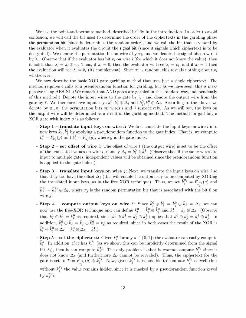
We use the point-and-permute method, described briefly in the introduction. In order to avoidconfusion, we will call the bit used to determine the order of the ciphertexts in the garbling phasethe permutation bit (since it determines the random order), and we call the bit that is viewed bythe evaluator when it evaluates the circuit the signal bit (since it signals which ciphertext is to bedecrypted). We denote the permutation bit on wire i by πi, and we denote the signal bit on wire iby λi. Observe that if the evaluator has bit vi on wire i (for which it does not know the value), thenit holds that λi = πi ⊕ vi. Thus, if πi = 0, then the evaluator will see λi = vi, and if πi = 1 thenthe evaluation will see λi = vi (its complement). Since πi is random, this reveals nothing about viwhatsoever.
We now describe the basic XOR gate garbling method that uses just a single ciphertext. Themethod requires 4 calls to a pseudorandom function for garbling, but as we have seen, this is inex-pensive using AES-NI. (We remark that AND gates are garbled in the standard way, independentlyof this method.) Denote the input wires to the gate by i, j and denote the output wire from thegate by `. We therefore have input keys k0
i , k0i ⊕∆i and k0
j , k0j ⊕∆j . According to the above, we
denote by πi, πj the permutation bits on wires i and j respectively. As we will see, the keys onthe output wire will be determined as a result of the garbling method. The method for garbling aXOR gate with index g is as follows:
- Step 1 – translate input keys on wire i: We first translate the input keys on wire i intonew keys k0
i , k1i by applying a pseudorandom function to the gate index. That is, we compute
k0i = Fk0
i(g) and k1
i = Fk1i(g), where g is the gate index.
- Step 2 – set offset of wire `: The offset of wire ` (the output wire) is set to be the offsetof the translated values on wire i, namely ∆` = k0
i ⊕ k1i . (Observe that if the same wires are
input to multiple gates, independent values will be obtained since the pseudorandom functionis applied to the gate index.)
- Step 3 – translate input keys on wire j: Next, we translate the input keys on wire j sothat they too have the offset ∆` (this will enable the output key to be computed by XORingthe translated input keys, as in the free XOR technique). Thus, we set k
πjj = F
kπjj
(g) and
kπjj = k
πjj ⊕∆`, where πj is the random permutation bit that is associated with the bit 0 on
wire j.
- Step 4 – compute output keys on wire `: Since k0i ⊕ k1
i = k0j ⊕ k1
j = ∆`, we can
now use the free-XOR technique and can define k0` = k0
i ⊕ k0j and k1
` = k0` ⊕ ∆`. (Observe
that k1i ⊕ k1
j = k0` as required, since k0
i ⊕ k1i = k0
j ⊕ k1j implies that k0
i ⊕ k0j = k1
i ⊕ k1j . In
addition, k0i ⊕ k1
j = k1i ⊕ k0
j = k1` as required, since in both cases the result of the XOR is
k0i ⊕ k0
j ⊕∆` = k0` ⊕∆` = k1
` .)
- Step 5 – set the ciphertext: Given kai for any a ∈ {0, 1}, the evaluator can easily computekai . In addition, if it has k
πjj (as we show, this can be implicitly determined from the signal
bit λi), then it can compute kπjj . The only problem is that it cannot compute k
πjj since it
does not know ∆` (and furthermore ∆` cannot be revealed). Thus, the ciphertext for thegate is set to T = F
kπjj
(g) ⊕ kπjj . Now, given kπjj it is possible to compute k
πjj as well (but
without kπjj the value remains hidden since it is masked by a pseudorandom function keyed
by kπjj ).
13

In order to evaluate a XOR gate g with ciphertext T , given a key ki on wire i and a key kj on wirej, the evaluator simply needs to compute ki = Fki(g) and either kj = Fkj (g) if it has signal bit 0,
or kj = Fkj (g) ⊕ T if it has signal bit 1. Then, the key on the output wire is obtained by finally
computing k` = ki ⊕ kj .The computational cost of garbling the gate is 4 pseudorandom function computations, and
the computational cost of evaluating the gate is 2 pseudorandom function computations. Mostsignificantly, the gate table includes only a single ciphertext.
Reducing the number of PRF calls to 3. Observe that the pseudorandom function is used toensure independence of the ∆ values between different gates. If we were to just take ∆` = k0
i ⊕ k1i ,
then the output ∆ from two different gates with the same input wire i would be the same, and onceagain correlation robustness or a related key assumption would be needed. Thus, it is necessaryto compute k0
i = Fk0i(g) and k1
i = Fk1i(g). In contrast, k
πjj can be taken to simply be k
πjj and
the pseudorandom function computation is not needed. This is because ∆` is fixed independentlyof wire j. Using this method, we can reduce the computational cost of garbling the XOR gatefrom 4 pseudorandom function computations to 3 pseudorandom function computations (and thecomputational cost of evaluating the gate is decreased from 2 to either 1 or 2 PRF computations).The proof of security with this optimization is somewhat more involved, and we therefore prove itseparately from the basic scheme.6
Garbling NOT Gates. When using free XOR, it is possible to efficiently garble NOT gates bysimply defining them to be XOR with a fixed wire that is always given value 1. Since the XORgates are free, this is highly efficient. However, since we are not using free XOR, a different methodneeds to be found. Fortunately, NOT gates can still be computed for free, and with no additionalassumption. In order to see this, let g be a NOT gate with input wire i and output wire j, andlet k0
i , k1i be the garbled values on wire i. Then, we simply define k0
j := k1i and k1
j := k0i . During
the garbling of the circuit, any gates receiving wire j as input will used these “reversed” values.Furthermore, when evaluating the circuit, if the value k0
i is given on wire i, then the result of theNOT gate is k1
j which equals k0i . Thus, nothing needs to be done. This trivially preserves security
since no additional information is provided in the garbled circuit.
3.3 Garbling Scheme Definitions
We use the notation of Bellare et al. [3] in which a garbling scheme consists of 4 algorithms:
- Garble(1n, c) → (C, e, d) is an algorithm that takes as input a security parameter 1n and adescription of a boolean circuit c, and returns a triple (C, e, d), where C represents a garbledcircuit, e represents input encoding information (i.e., all the keys on the input wires) and drepresents output decoding information (i.e., all the keys on the output wires).
6It may be tempting to propose that one of k0i , k
1i will also remain the same; i.e., set kπii = kπii and kπii = F
kπii
(g).
However, in this case, if the evaluator happens to have kπii and kπjj then it can compute T ⊕F
kπii
(g)⊕Fkπjj
(g). Note
that T = Fkπjj
(g) ⊕ kπjj = Fkπjj
(g) ⊕ kπjj ⊕ ∆` = Fkπjj
(g) ⊕ kπjj ⊕ kπii ⊕ Fkπii (g) and so the result obtained by the
evaluator is kπjj ⊕ k
πii = k
πjj ⊕ k
πii . If these keys are used in other gates, then an attacker sees the XOR of two keys
and encryptions computed with each key separately. This is once again a related-key type assumption.
14

- Encode(e, x) → X is a function that takes as input encoding information e and input x andreturns garbled input (i.e., the keys on the input wires that are associated with the concreteinput x).
- Eval(C,X) → Y is a function that takes as input a garbled circuit C and garbled input Xand returns garbled output Y (i.e., the keys on the output wires that are associated with theconcrete output y = c(x)).
- Decode(Y, d)→ y is a function that takes as input decoding information d and garbled outputY and returns either the real output y of the circuit or ⊥.
A secure garbling scheme should satisfy three security requirements:
- Privacy: The triple (C,X, d) should not reveal any information about x that cannot belearned directly from c(x). More formally, there exists a simulator S that receives input(1n, c, c(x)) and outputs a simulated garbled circuit with garbled input and decoding infor-mation that is indistinguishable from (C,X, d) generated using the real garbling functionsGarble(1n, c) and Encode(e, x). Observe that S knows the output c(x) and does not know theinput x.
- Obliviousness: (C,X) should not reveal any information about x. More formally, thereexists a simulator S that receives input (1n, c) and outputs a simulated garbled circuit withgarbled input that is indistinguishable from (C,X) generated using the real garbling functionsGarble(1n, c) and Encode(e, x). Observe that S here is not even given the output.
- Authenticity: Given (C,X) as input, no adversary should be able to produce garbled outputY that when decoded provides a value that does not equal c(x) or abort, except with negligibleprobability.
For each security definition we define an experiment that formalizes the adversary’s task. Inthe following, G denotes a garbling scheme that consists of the 4 algorithms stated above, and Sdenotes a simulator.
15

The privacy experiment ExptprivG,A,S(n):
1. Invoke adversary A: compute (c, x)← A(1n)2. Choose a random β ∈ {0, 1}3. If β = 0: compute (C, e, d)← Garble(1n, c) and X ← Encode(e, x)
Else: compute (C,X, d)← S(1n, c, c(x))4. Give A the challenge (C,X, d) and obtain its guess: β′ ← A(C,X, d)5. Output 1 if and only if β′ = β
The obliviousness experiment ExptoblvG,S,A(n):
1. Invoke adversary: (c, x)← A(1n)2. Choose a random β ∈ {0, 1}3. If β = 0: compute (C, e, d)← Garble(1n, c) and X ← Encode(e, x)
Else: compute (C,X)← S(1n, c)4. Give A the challenge (C,X) and obtain its guess: β′ ← A(C,X)5. Output 1 if and only if β′ = β
The authenticity experiment ExptauthG,A (n):
1. Invoke adversary: (c, x)← A(1n)2. Compute (C, e, d)← Garble(1n, c) and X ← Encode(e, x)
3. Give A the challenge (C,X) and obtain its output: Y ← A(C,X)
4. Output 1 if and only if Decode(Y , d) /∈ {⊥, c(x)}
The basic non-triviality requirement for a garbling scheme, called correctness, is that for everycircuit c and input x ∈ {0, 1}poly(n), it holds that Decode(Eval(C,Encode(e, x)), d) = c(x) exceptwith negligible probability, where (C, e, d)← Garble(1n, c).
Definition 3.1 (Garbled Circuit Security) A garbling scheme is secure if it is correct, andachieves privacy, obliviousness and authenticity as follows:
1. A garbling scheme G achieves privacy if for every probabilistic polynomial-time adversary Athere exists a probabilistic-polynomial time simulator S and a negligible function µ such thatfor every n ∈ N:
Pr[Exptpriv
G,A,S(n) = 1]≤ 1
2+ µ(n).
2. A garbling scheme G achieves obliviousness if for every probabilistic polynomial-time adversaryA there exists a probabilistic-polynomial time simulator S and a negligible function µ suchthat for every n ∈ N:
Pr[Exptoblv
G,A,S(n) = 1]≤ 1
2+ µ(n).
3. A garbling scheme G achieves authenticity if for every probabilistic polynomial-time adversaryA there exists a negligible function µ such that for every n ∈ N:
Pr[Exptauth
G,A (n) = 1]< µ(n)
16

3.4 Our Garbling Scheme in Detail
In this section, we provide a full specification of our garbling scheme. In this description, we usethe standard 4-3 row reduction technique. In later sections, we will incorporate our new 4-2 rowreduction scheme. Our garbling scheme uses a pseudorandom function that takes an n-bit key, andhas input and output of length n + 1. That is, F : {0, 1}n × {0, 1}n+1 → {0, 1}n+1 (formally, weconsider a family of functions, where for every n ∈ N the function is of this type). We denote byFk(x)[1..n] the first n bits of the output of Fk(x), and we denote by x‖y the concatenation of xwith y. We begin by defining the method for garbling XOR and AND gates in Figures 1 and 2 (forsimplicity we only consider XOR, AND and NOT gates; the AND gate method can be extendedto any gate type), and then proceed to the high-level garbling algorithm in Figure 3. Finally, wedescribe the encoding, evaluation and decoding algorithms.
Procedure GbXOR(k0i , k
1i , k
0j , k
1j , πi, πj):
1. Set the output wire permutation bit for the bit ‘0’: π` := πi ⊕ πj
2. Compute translated keys for wire i: k0i := Fk0
i(g‖πi)[1..n] and k1
i := Fk1i(g‖πi)[1..n]
3. Compute new offset for the output wire: ∆` := k0i ⊕ k1
i
4. Compute translated keys for wire j and the ciphertext for this gate:
(a) If πj = 0, set k0j := Fk0
j(g‖0)[1..n], k1
j := k0j ⊕∆` and T := Fk1
j(g‖1)[1..n]⊕ k1
j
(b) If πj = 1, set k1j := Fk1
j(g‖0)[1..n], k0
j := k1j ⊕∆` and T := Fk0
j(g‖1)[1..n]⊕ k0
j
5. Compute the keys for the output wire `: k0` := k0
i ⊕ k0j and k1
` := k0` ⊕∆`
6. Return (k0` , k
1` , π`, T )
Figure 1: Garbling XOR gates
Procedure GbAND(k0i , k
1i , k
0j , k
1j , πi, πj):
1. Compute K0 = Fkπii(g‖00)⊕ F
kπjj
(g‖00)
2. Set the output wire keys and permutation bits:
(a) If πi = πj = 1, then choose a random k0`‖π` ← {0, 1}n+1 and set k1
` := K0[1..n]
(b) Else, set k0`‖π` := K0 and choose a random k1
` ← {0, 1}n
Denote K0` = k0
`‖π` and K1` = k1
`‖π`.
3. Compute the gate ciphertexts: Let g(·, ·) denote the gate function. Then,
T1 = Fkπii(g‖01)⊕ F
kπjj
(g‖01)⊕Kg(πi,πj)`
T2 = Fkπii(g‖10)⊕ F
kπjj
(g‖10)⊕Kg(πi,πj)`
T3 = Fkπii(g‖11)⊕ F
kπjj
(g‖11)⊕Kg(πi,πj)`
4. Return (k0` , k
1` , π`, T1, T2, T3)
Figure 2: Garbling AND gates
17

The garbling algorithm Garble(1n, c):
1. For each input wire j in c:
(a) Choose two random keys: k0j , k
1j ← {0, 1}n
(b) Choose a permutation bit for the bit ‘0’: πj ← {0, 1}(c) Prepare the encoding information: e[j, 0] := k0
j‖πj and e[j, 1] := k1j‖πj
2. In topological order, for each gate g in circuit c:
(a) If g is a XOR gate with input wires i, j and output wire `:
i. (k0` , k
1` , π`, T )← GbXOR(k0
i , k1i , k
0j , k
1j , πi, πj)
ii. Set the keys on the output wire ` to be k0` , k
1` and the permutation bit to be π`
iii. Set the garbled table for the gate: C[g] := T
(b) If g is an AND gate with input wires i, j and output wire `:
i. (k0` , k
1` , π`, T1, T2, T3)← GbAND(k0
i , k1i , k
0j , k
1j , πi, πj)
ii. Set the keys on the output wire ` to be k0` , k
1` and the permutation bit to be π`
iii. Set the garbled table for the gate: C[g] := (T1, T2, T3)
(c) If g is a NOT gate with input wire i and output wire `:
i. Set k0` = k1
i and k1` = k0
i and set π` = πi
ii. There is no garbled gate
3. For each circuit-output wire j in c, prepare the decoding information: d[j, 0] := Fkπjj
(out‖πj) and
d[j, 1] := Fkπjj
(out‖πj)
4. Return (C, e, d)
Figure 3: The full garbling algorithm
We now proceed to describe the encoding, evaluation and decoding algorithms. The encodingand decoding algorithms are straightforward and consist merely of mapping the plaintext bit to thegarbled value and vice versa. Observe that in the evaluation algorithm we refer to the signal bitλi on wire i. The difference between λi here and πi used in the garbling is that λi is the “public”signal bit that the evaluator sees. The invariant over this value is that λi always equals the XORof πi and the actual value on the wire (associated with the encoding X).
Procedure Encode(e, x):
1. For i=1 to |x|: X[i] := e[i, xi]
2. Return X
Figure 4: The encoding algorithm
18

Procedure Eval(C,X):
1. For every input wire j in c, set kj‖λj := X[j]
2. For each gate g in c, in topological order:
(a) If g is a XOR gate with input wires i, j and output wire `:
i. Compute the output wire key: k` := Fki(g‖λi)[1..n]⊕ Fkj (g‖λj)[1..n]⊕ λj · C[g]
ii. Compute the output wire signal bit: λ` := λi ⊕ λj(b) If g is an AND gate with input wires i, j and output wire `:
i. Compute the output wire key and signal bit: k`‖λ` := T ⊕Fki(g‖λiλj)⊕Fki(g‖λiλj), whereT is the entry T2λi+λj in C[g] (note that if λi = λj = 0 then implicitly we define T = 0).
(c) If g is a NOT gate with input wire i and output wire `, then set k` := ki and λ` = λi
3. For each output wire j in c, set Y [j] := Fkj (out‖λj)
4. Return Y
Figure 5: The evaluation algorithm
Procedure Decode(Y, d):
1. For i=1 to |Y |:
(a) If Y [i] = d[i, 0], then y[i] := 0
(b) Else, if Y [i] = d[i, 1], then y[i] := 1
(c) Else, return ⊥
2. Return y
Figure 6: The decoding algorithm
Correctness. We begin by demonstrating correctness. This is immediate for AND and NOTgates; we therefore show that it also holds for XOR gates. Observe that the ciphertext in aXOR gate with input wires i, j and output wire ` equals C[g] = F
kπjj
(g‖1)[1..n] ⊕ kπjj . However,
kπjj = k
πjj ⊕∆` = F
kπjj
(g‖0)[1..n]⊕∆` and ∆` = kπii ⊕ kπii = Fkπii
(g‖0)[1..n]⊕Fkπii
(g‖1)[1..n]. Thus,
C[g] = Fkπii(g‖0)[1..n]⊕ F
kπii
(g‖1)[1..n]⊕ Fkπjj
(g‖0)[1..n]⊕ Fkπjj
(g‖1)[1..n] (1)
where πi, πj are the permutation bits that are associated with the bit 0 on wires i, j respectively.Now, assume that the evaluator holds the keys kvii and k
vjj that are associated with the (plain)
bits vi, vj . Then, according to procedure Eval, it computes: Fkvii(g‖λi)[1..n] ⊕ F
kvjj
(g‖λj)[1..n] ⊕λjC[g]. Thus, if λj = 0 then it computes
Fkvii(g‖λi)[1..n]⊕ F
kvjj
(g‖0)[1..n] (2)
and if λj = 1 then it computes
Fkvii(g‖λi)[1..n]⊕F
kvjj
(g‖1)[1..n]⊕Fkπii (g‖0)[1..n]⊕Fkπii
(g‖1)[1..n]⊕Fkπjj
(g‖0)[1..n]⊕Fkπjj
(g‖1)[1..n]. (3)
19

Recall that λj = vj ⊕ πj . Thus, if λj = 1 then vj = πj ⊕ 1 = πj , and if λj = 0 then vj = πj .Likewise, for λi, vi and πi.
We first consider the case that λj = 0. Note that in wire i, we have that kvii = Fkvii(g‖πi⊕vi)[1..n]
(see Step 2 in Procedure GbXOR). Thus, by the above relation between λi, vi and πi, it follows thatkvii = Fkvii
(g‖λi)[1..n]. Furthermore, by Step 4 in Procedure GbXOR, we have that kπjj = F
kπjj
(g‖0).
In this case of λj = 0 we have that vj = πj and thus kvjj = F
kvjj
(g‖0). Combining this with Eq. (2),
we conclude that when λj = 0, the evaluator computes
Fkvii(g‖λi)[1..n]⊕ F
kvjj
(g‖0)[1..n] = kvii ⊕ kvjj .
Now consider λj = 1. Observe that Fkvii(g‖λi)[1..n] ∈
{Fkπii
(g‖0)[1..n], Fkπii
(g‖1)[1..n]}
and that
if λi = 0 then vi = πi and otherwise vi = πi. Thus, Fkvii(g‖λi)[1..n] cancels out and
Fkvii(g‖λi)[1..n]⊕ Fkπii (g‖0)[1..n]⊕ F
kπii
(g‖1)[1..n] = Fkvii
(g‖λi)[1..n].
If vi = 0 then λi = πi and we have Fkvii
(g‖λi)[1..n] = Fk1i(g‖πi)[1..n], which is exactly k1
i ac-
cording to Step 2 of Procedure GbXOR. If vi = 1 then λi = πi and we have Fkvii
(g‖λi)[1..n] =
Fk0i(g‖πi)[1..n], which is exactly k0
i . In both cases, we receive kvii . Likewise Fkvjj
(g‖1)[1..n] =
Fkπjj
(g‖1)[1..n] because λj = 1 and so vj = πj . Thus, this element cancels out and
Fkvjj
(g‖1)[1..n]⊕ Fkπjj
(g‖0)[1..n]⊕ Fkπjj
(g‖1)[1..n] = Fkπjj
(g‖0)[1..n] = kπjj = k
vjj .
where the second last equality is from Step 4 in Procedure GbXOR. We conclude that when λj = 1
the evaluator receives kvii ⊕ kvjj .
Since k0i ⊕ k1
i = k0j ⊕ k1
j , we conclude that the output equals kvii ⊕ kvjj for both values of λj .
The fact that this yields the correct output is immediate from the way the output wire values arechosen for the gate.
Intuition For security. As just explained, the ciphertext in a XOR gate is the result of XORingthe four outputs of the pseudorandom function:
C[g] = Fkπii(g‖0)[1..n]⊕ F
kπii
(g‖1)[1..n]⊕ Fkπjj
(g‖0)[1..n]⊕ Fkπjj
(g‖1)[1..n]
Each one of these four computations uses a different key, from which only two keys are known tothe evaluator. Since we use the gate index as an input to the function, we are guaranteed thatwhen a wire enters multiple gates, the pseudorandom values we compute will be different in eachof the gates. Thus, the ciphertext looks like a random string to the evaluator. In addition, theoutput-wire key values are determined by the result of the pseudorandom function computationas well. Thus, they are new keys that do not appear elsewhere in the circuit. We stress that thefour values in the equation above are not the four new translated keys. If that was the case, thenXORing them would yield 0, because the same offset is used in both wires after the translation.Instead, the first three values are the translated keys, but the last value is just a pseudorandomstring that is used to mask them in a “one-time pad”-like encryption.
20

A similar argument applies for AND gates. Since the evaluator can compute only two of the eightPRF computations using the two keys it holds, and since the values that are used in computing thegarbled table are unique and do not appear elsewhere in the circuit (again, this is ensured by usingthe gate index and the permutation bits as input to each pseudorandom function computation),the gate ciphertexts that are not associated with the keys known to the evaluator, look random tothe evaluator.
3.5 Proof of Security
3.5.1 Preliminaries
We begin by defining an experiment based on pseudorandom functions that will be convenient forproving security of the garbling scheme. As we have mentioned, we consider a family of functionsF = {Fn}n∈N where for every n it holds that Fn : {0, 1}n × {0, 1}n+1 → {0, 1}n+1. For clarity, wedrop the subscript and write Fk(x) where k ∈ {0, 1}n instead of Fn(k, x).
We now define the experiment, call 2PRF . In this experiment, the distinguisher/adversaryis given access to four oracles, divided into two pairs. The second and fourth oracles are alwayspseudorandom functions Fk1 and Fk2 , respectively. In contrast, the first and third oracles are eitherthe same pseudorandom functions Fk1 and Fk2 , respectively, or independent truly random functionsf1 and f3. Clearly, if A can make the same query to the first and second oracle, or to the third andfourth oracle, then it can easily distinguish the cases. The security requirement is that as long as itdoes not make such queries, it cannot distinguish the cases. We prove that this property holds forany pseudorandom function. The experiment is formally defined in Figure 7, and 2PRF security isformalized in Definition 3.2.
Experiment Expt2PRFF ,A (n, σ) :
1. Choose random keys k1, k2 ← {0, 1}n for the pseudorandom function, and choose two trulyrandom functions f1, f2. If σ = 0, set (O(1),O(2),O(3),O(4)) = (Fk1 , Fk1 , Fk2 , Fk2); else, set(O(1),O(2),O(3),O(4)) = (f1, Fk1 , f
2, Fk2)
2. The adversary A is invoked upon input 1n
3. When A makes a query (j, x) to its oracles with j ∈ {1, 2, 3, 4} and x ∈ {0, 1}n+1, answer asfollows:
• if j ∈ {1, 2} and x was already queried to {1, 2} \ {j}, return ⊥• if j ∈ {3, 4} and x was already queried to {3, 4} \ {j}, return ⊥• Otherwise, return O(j)(x)
4. A outputs a bit σ′, and this is the output of the experiment
Figure 7: The 2PRF experiment
Definition 3.2 Let F = {Fn}n∈N be an efficient family of functions where for every n, Fn :{0, 1}n × {0, 1}n+1 → {0, 1}n+1. Family F is a 2PRF if for every probabilistic-polynomial time
21

adversary A there exists a negligible function µ such that for every n,∣∣Pr[Expt2PRFF ,A (n, 1) = 1]− Pr[Expt2PRFA (n, 0)] = 1∣∣ < µ(n)
The following lemma shows that pseudorandomness of Fk is sufficient for it to be 2PRF as well.
Lemma 3.3 If F is a family of pseudorandom functions, then it is a 2PRF.
Proof: Assume that F is a PRF. Denote by Exptg1,g2,g3,g4
A (n) the experiment where A is givenoracle access to functions g1, g2, g3, g4 (under the input limitations outlined in the experiment).
Using this notation, we have that Expt2PRFF ,A (n, 0) = ExptFk1
,Fk1,Fk2
,Fk2A (n) and Expt2PRFF ,A (n, 1) =
Exptf1,Fk1
,f2,Fk2A (n).
First, a straightforward reduction to the security of the pseudorandom function (with a hybridfor two pseudorandom functions) yields that for every probabilistic-polynomial time adversary Athere exists a negligible function µ such that for every n,∣∣∣Pr
[Expt
Fk1,Fk1
,Fk2,Fk2
A (n) = 1]− Pr
[Exptf
1,f1,f2,f2
A (n) = 1]∣∣∣ ≤ µ(n).
Note that oracle access to the same random function twice or to two different random functions isidentical when there is a constraint that the same input cannot be supplied to both oracles. Thus,for every adversary A and for every n,
Pr[Exptf
1,f1,f2,f2
A (n) = 1]
= Pr[Exptf
1,f3,f2,f4
A (n) = 1].
Next, we claim that for every probabilistic-polynomial time adversary A there exists a negligiblefunction µ such that for every n,∣∣∣Pr
[Exptf
1,f3,f2,f4
A (n) = 1]− Pr
[Expt
f1,Fk1,f2,f4
A (n) = 1]∣∣∣ ≤ µ(n).
This follows from a direct reduction to the pseudorandomness of F (the reduction simulatesf1, f3, f4 itself and uses its oracle to either have f2 or Fk1). Likewise, a direction reduction yieldsthat for every probabilistic-polynomial time adversary A there exists a negligible function µ suchthat for every n,∣∣∣Pr
[Expt
f1,Fk1,f2,f4
A (n) = 1]− Pr
[Expt
f1,Fk1,f2,Fk2
A (n) = 1]∣∣∣ ≤ µ(n).
Here the reduction simulates f1, Fk1 , f2 itself. Combining all of the above, we conclude that for
every adversary A there exists a negligible function µ such that for every n,∣∣Pr[Expt2PRFF ,A (n, 0) = 1
]− Pr
[Expt2PRFF ,A (n, 1) = 1
]∣∣=
∣∣∣Pr[Expt
Fk1,Fk1
,Fk2,Fk2
A (n) = 1]− Pr
[Expt
f1,Fk1,f2,Fk2
A (n) = 1]∣∣∣ ≤ µ(n).
22

3.5.2 The Proof of Security of Our Garbling Scheme
We begin by proving that our garbling scheme achieves privacy. Let G denote our garbling scheme.Our proof follows the high-level structure of [18], with modifications as needed for our garblingscheme.
Theorem 3.4 If F is a family of pseudorandom functions, then the garbling scheme G achievesprivacy.
Proof: We begin by describing a simulator S for the Exptpriv privacy experiment. S is invokedwith input (1n, c, c(x)) and works as follows. As we will show, S will define an active key on everywire. This key will be the one that is “obtained” in the evaluation procedure. The other key is notactive, and is actually never explicitly defined. Rather, all the ciphertexts in the gates that are not“decrypted” in the evaluation are chosen at random.
1. For each input wire j in circuit c:
(a) Choose an active key: kj ← {0, 1}n
(b) Choose an active signal bit λj ← {0, 1}(c) Prepare the garbled input data: X[j] = kj‖λj
2. In topological order, for each gate g in c:
(a) If g is a XOR gate with input wires i, j and output wire `:
i. Compute the active output-wire signal bit: λ` := λi ⊕ λjii. Compute a translated new key for wire i: ki := Fki(g‖λi)[1..n]
iii. Compute a translated new key for wire j, and the ciphertext for this gate:
A. If λj = 0, set kj := Fkj (g‖0)[1..n] and C[g]← {0, 1}n (in this case, the translatedkey is obtained by computing F and so is correctly computed, but the ciphertextis not used and so is random)
B. If λj = 1, set kj ← {0, 1}n and C[g] := Fkj (g‖1)[1..n] ⊕ kj (in this case, thetranslated key is obtained via the ciphertext, and so the ciphertext is correctlycomputed, but using a random key)
iv. Compute the output wire active key: k` := ki ⊕ kj(b) If g is an AND gate with input wires i, j and output wire `:
i. Set the output-wire active key and signal bit:
A. If λi = λj = 0, set k`‖λ` := Fki(g‖00)⊕ Fkj (g‖00) (in this case, the output keyis computed via F and so must be set in this way)
B. Else, set k`‖λ` ← {0, 1}n+1 (in this case, the output key is computed from theciphertexts and is chosen at random)
ii. Compute the gate’s ciphertexts (they are random except for the one that is openedaccording to the active signal bits):
A. If 2λi + λj 6= 0, then T2λi+λj := Fki(g‖λiλj)⊕ Fkj (g‖λiλj)⊕ k`‖λ`B. For α ∈ {1, 2, 3} \ {2λi + λj} : Tα ← {0, 1}n+1
C. C[g]← T1, T2, T3
23
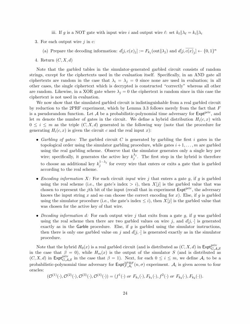
iii. If g is a NOT gate with input wire i and output wire `: set k`‖λ` = ki‖λi
3. For each output wire j in c:
(a) Prepare the decoding information: d[j, c(x)j ] := Fkj (out‖λj) and d[j, c(x)j ]← {0, 1}n
4. Return (C,X, d)
Note that the garbled tables in the simulator-generated garbled circuit consists of randomstrings, except for the ciphertexts used in the evaluation itself. Specifically, in an AND gate allciphertexts are random in the case that λi = λj = 0 since none are used in evaluation; in allother cases, the single ciphertext which is decrypted is constructed “correctly” whereas all otherare random. Likewise, in a XOR gate where λj = 0 the ciphertext is random since in this case theciphertext is not used in evaluation.
We now show that the simulated garbled circuit is indistinguishable from a real garbled circuitby reduction to the 2PRF experiment, which by Lemma 3.3 follows merely from the fact that Fis a pseudorandom function. Let A be a probabilistic-polynomial time adversary for Exptpriv, andlet m denote the number of gates in the circuit. We define a hybrid distribution Hi(c, x) with0 ≤ i ≤ m as the triple (C,X, d) generated in the following way (note that the procedure forgenerating Hi(c, x) is given the circuit c and the real input x):
• Garbling of gates: The garbled circuit C is generated by garbling the first i gates in thetopological order using the simulator garbling procedure, while gates i+ 1, . . . ,m are garbledusing the real garbling scheme. Observe that the simulator generates only a single key per
wire; specifically, it generates the active key kλjj . The first step in the hybrid is therefore
to choose an additional key k1−λjj for every wire that enters or exits a gate that is garbled
according to the real scheme.
• Encoding information X: For each circuit input wire j that enters a gate g, if g is garbledusing the real scheme (i.e., the gate’s index > i), then X[j] is the garbled value that waschosen to represent the jth bit of the input (recall that in experiment Exptpriv, the adversaryknows the input string x and so can choose the correct encoding for x). Else, if g is garbledusing the simulator procedure (i.e., the gate’s index ≤ i), then X[j] is the garbled value thatwas chosen for the active key of that wire.
• Decoding information d: For each output wire j that exits from a gate g, if g was garbledusing the real scheme then there are two garbled values on wire j, and d[j, ·] is generatedexactly as in the Garble procedure. Else, if g is garbled using the simulator instructions,then there is only one garbled value on j and d[j, ·] is generated exactly as in the simulatorprocedure.
Note that the hybrid H0(x) is a real garbled circuit (and is distributed as (C,X, d) in ExptprivG,A,S
in the case that β = 0), while Hm(x) is the output of the simulator S (and is distributed as(C,X, d) in Exptpriv
G,A,S in the case that β = 1). Next, for each 0 ≤ i ≤ m, we define Ai to be a
probabilistic-polynomial time adversary for Expt2PRFF ,Ai (n, σ) experiment. Ai is given access to fouroracles:
(O(1)(·),O(2)(·),O(3)(·),O(4)(·)) = (f1(·) or Fk1(·), Fk1(·), f2(·) or Fk2(·), Fk2(·)).
24
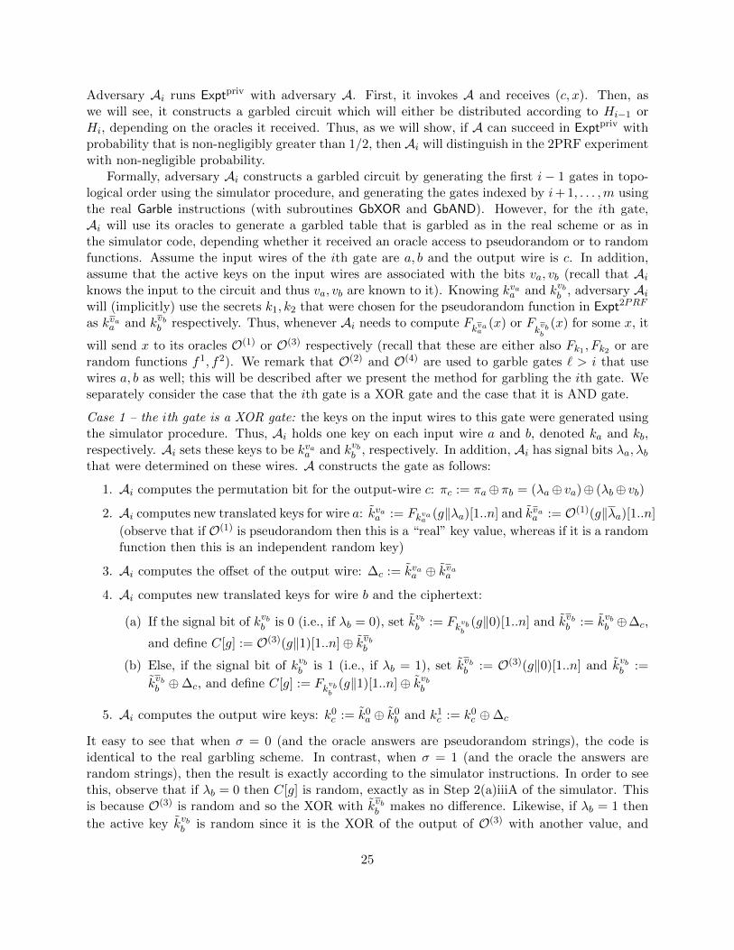
Adversary Ai runs Exptpriv with adversary A. First, it invokes A and receives (c, x). Then, aswe will see, it constructs a garbled circuit which will either be distributed according to Hi−1 orHi, depending on the oracles it received. Thus, as we will show, if A can succeed in Exptpriv withprobability that is non-negligibly greater than 1/2, then Ai will distinguish in the 2PRF experimentwith non-negligible probability.
Formally, adversary Ai constructs a garbled circuit by generating the first i− 1 gates in topo-logical order using the simulator procedure, and generating the gates indexed by i+ 1, . . . ,m usingthe real Garble instructions (with subroutines GbXOR and GbAND). However, for the ith gate,Ai will use its oracles to generate a garbled table that is garbled as in the real scheme or as inthe simulator code, depending whether it received an oracle access to pseudorandom or to randomfunctions. Assume the input wires of the ith gate are a, b and the output wire is c. In addition,assume that the active keys on the input wires are associated with the bits va, vb (recall that Aiknows the input to the circuit and thus va, vb are known to it). Knowing kvaa and kvbb , adversary Aiwill (implicitly) use the secrets k1, k2 that were chosen for the pseudorandom function in Expt2PRF
as kvaa and kvbb respectively. Thus, whenever Ai needs to compute Fkvaa
(x) or Fkvbb
(x) for some x, it
will send x to its oracles O(1) or O(3) respectively (recall that these are either also Fk1 , Fk2 or arerandom functions f1, f2). We remark that O(2) and O(4) are used to garble gates ` > i that usewires a, b as well; this will be described after we present the method for garbling the ith gate. Weseparately consider the case that the ith gate is a XOR gate and the case that it is AND gate.
Case 1 – the ith gate is a XOR gate: the keys on the input wires to this gate were generated usingthe simulator procedure. Thus, Ai holds one key on each input wire a and b, denoted ka and kb,respectively. Ai sets these keys to be kvaa and kvbb , respectively. In addition, Ai has signal bits λa, λbthat were determined on these wires. A constructs the gate as follows:
1. Ai computes the permutation bit for the output-wire c: πc := πa⊕πb = (λa⊕ va)⊕ (λb⊕ vb)
2. Ai computes new translated keys for wire a: kvaa := Fkvaa (g‖λa)[1..n] and kvaa := O(1)(g‖λa)[1..n]
(observe that if O(1) is pseudorandom then this is a “real” key value, whereas if it is a randomfunction then this is an independent random key)
3. Ai computes the offset of the output wire: ∆c := kvaa ⊕ kvaa4. Ai computes new translated keys for wire b and the ciphertext:
(a) If the signal bit of kvbb is 0 (i.e., if λb = 0), set kvbb := Fkvbb(g‖0)[1..n] and kvbb := kvbb ⊕∆c,
and define C[g] := O(3)(g‖1)[1..n]⊕ kvbb(b) Else, if the signal bit of kvbb is 1 (i.e., if λb = 1), set kvbb := O(3)(g‖0)[1..n] and kvbb :=
kvbb ⊕∆c, and define C[g] := Fkvbb(g‖1)[1..n]⊕ kvbb
5. Ai computes the output wire keys: k0c := k0
a ⊕ k0b and k1
c := k0c ⊕∆c
It easy to see that when σ = 0 (and the oracle answers are pseudorandom strings), the code isidentical to the real garbling scheme. In contrast, when σ = 1 (and the oracle the answers arerandom strings), then the result is exactly according to the simulator instructions. In order to seethis, observe that if λb = 0 then C[g] is random, exactly as in Step 2(a)iiiA of the simulator. Thisis because O(3) is random and so the XOR with kvbb makes no difference. Likewise, if λb = 1 then
the active key kvbb is random since it is the XOR of the output of O(3) with another value, and
25

C[g] is the XOR of this key with the appropriate output from Fkvbb. Thus, this is also exactly as in
Step 2(a)iiiB of the simulator.
Case 2 – the ith gate is an AND gate: As before, for wires a and b, Ai has two keys kvaa , kvbb , two
signal bits λa, λb and the bits va, vb that are on the wires. Then it does the following:
1. Compute the values K0, . . . ,K3:
K2λa+λb := Fkvaa (g‖λaλb)⊕ Fkvbb (g‖λaλb) K2λa+λb:= Fkvaa (g‖λaλb)⊕O(3)(g‖λaλb)
K2λa+λb:= O(1)(g‖λaλb)⊕ Fkvbb (g‖λaλb) K2λa+λb
:= O(1)(g‖λaλb)⊕O(3)(g‖λaλb)
2. Set the output wire keys and permutation bits:
(a) Compute: πa = va ⊕ λa and πb = vb ⊕ λb(b) If πa = πb = 1, set k0
c‖πc ← {0, 1}n+1 and k1c := K0[1..n]
(c) Else, set k0c‖πc := K0 and k1
c ← {0, 1}n
Denote K0c := k0
c‖πc and K1c := k1
c‖πc
3. Compute the ciphertexts: For α ∈ {1, 2, 3},
(a) If α = 2πa + πb, then Tα := Kα ⊕K1c
(b) Else: Tα := Kα ⊕K0c
Set C[g]← {T1, T2, T3}
As in the previous case, when σ = 0, the code is identical to real garbling scheme. When σ = 1,the answers of the oracles are random strings, and therefore all the rows in the garbled table arerandom as well, except for the row that is pointed to by the signal bits of the active keys (the rowT2λa+λb where the adversary computes the value of K2λa+λb directly using the keys it holds). Thus,the gate is garbled as in the simulation.
We conclude that when σ = 0, the ith gate is garbled as in the real garbling scheme, while whenσ = 1 the ith gate is garbled as in the simulator procedure. However, to complete the constructionof the garbled circuit, Ai needs to construct all the gates ` > i. For a gate ` > i with input-wiresthat are output from the ith gate and greater, Ai has both keys on the wires and so can computethe gate just like in the real garbling procedure. If a gate ` > i has an input-wire that is output froma gate j < i that does not equal a or b, then Ai simply chooses the (inactive) key at random, like inthe hybrid definition. Finally, for a gate that has an input wire a or b, the gate is constructed usedoracles O(2) and O(4) and the same code for gate i (except with these oracles instead of O(1) andO(3)). Since these oracles always use the pseudorandom functions, it follows that the computationof the gate is always according to the real garbling method. (Note that when garbling the `th gate,each of the queries to these oracles includes the gate’s number. Thus we are guaranteed that thesequeries were not sent to O(1) and O(3) when Ai garbled the ith gate, as required in Expt2PRFF ,A (n, σ)experiment.)
Concluding the proof, when σ = 0, Ai constructs the hybrid Hi−1(x), while when σ = 1,Ai constructs the hybrid Hi(x). We therefore construct a single adversary A′ for 2PRF whochooses a random i and then runs Ai with adversary A. By a standard hybrid argument, if A
26

succeeds with non-negligible probability in Exptpriv then A′ distinguishes between Expt2PRFF ,A (n, 0)
and Expt2PRFF ,A (n, 1), with non-negligible probability. This contradicts the assumption that F is afamily of pseudorandom functions.
Achieving obliviousness and authenticity. In order to satisfy the obliviousness requirement,we need to construct a simulator that outputs (C,X) given only c as an input. Note that thesimulator S constructed above for the privacy requirement outputs the triple (C,X, d). However,S uses c only for generating (C,X), and in particular the output c(x) is used only for generatingd. Thus, we can simply remove the generation of the decoding information from S’s instruction,and we obtain a simulator that generates only (C,X) as required. Proving that this simulator’soutput is indistinguishable from (C,X) generated by the real scheme, is the same as in the proofof privacy.7
Regarding authenticity, we need to show that a probabilistic-polynomial time adversary A thatis given (C,X) as input can output Y such that Decode(Y , d) /∈ {c(x),⊥} with at most negligibleprobability. Note that if we give A the pair (C,X) generated by our simulator, it can succeed onlywith probability at most 2−n. This is due to the fact that in the simulated garbled circuit, for eachoutput wire j corresponding to the jth output bit, d[j, c(x)j ] is a random string. Now, if given the
real (C,X), the adversary can output such a Y with non-negligible probability, then it could be usedby an adversary given (C,X, d), to break the privacy property, in contradiction to Theorem 3.4.Observe that since the adversary in the privacy experiment is given all of the decoding informationd, it can efficiently verify if A output a Y with the property that Decode(Y , d) /∈ {c(x),⊥}.
3.6 XOR Gates with Only Three PRF Computations
Our garbling method requires four calls to the pseudorandom function for garbling XOR gates,where each call uses a different key. In this section we show that it is possible to remove one ofthese calls by leaving one of the input keys unchanged. Recall that our ciphertext for a XOR gateg with input wires i, j and output wire ` is:
C[g] = Fkπii(g‖0)[1..n]⊕ F
kπii
(g‖1)[1..n]⊕ Fkπjj
(g‖0)[1..n]⊕ Fkπjj
(g‖1)[1..n] (4)
Assume the evaluator has the keys kvii , kvjj and the signal bits λi, λj when computing the gate.
Then, using the ciphertext C[g] it computes C[g]⊕ Fkvii (g‖λi)[1..n]⊕ Fkvjj
(g‖λj)[1..n] and obtains
Fkvii
(g‖λi)[1..n] ⊕ Fkvjj
(g‖λj), which is the XOR of two pseudorandom values. If we leave, for
example, the value of kvjj unchanged – i.e., use it in Eq. (4) instead of F
kvjj
(g‖λj) – the evaluator
will be able to compute Fkvii
(g‖λi)[1..n]⊕kvjj . Observe that the evaluator still cannot learn anything
since one of the two values is a new pseudorandom value that does not appear anywhere else inthe circuit (taking the gate index g as an input to F ensures that if a wire i or j enters multiplegates, then we compute a different value for each gate). Therefore, the ciphertext is pseudorandomas required. In addition, since the two keys on wire i are still translated to new keys, the outputwire keys, generated in the same way as before, are guaranteed to obtain new fresh values. (See
7Recall that in the reduction the adversary Ai knows the input x. However, in the experiment in the proof ofobliviousness, A also outputs x and so it is known. Thus, the same reduction works.
27

Footnote 6 as to why we cannot use the same method to remove one of the pseudorandom functioncalls on wire i as well.)
The modified garbling scheme. Denote the modified scheme where only three pseudorandomfunction calls are made by G′. Figure 8 presents the modifications in G′ compared to our basescheme; only the items in GbXOR and Eval that were changed appear, and the actual changesappear in bold. The procedure GbXOR is changed by not changing the key on wire j that representsthe bit vj when vj ⊕ πj = 0; i.e., k0
j is set to k0j instead of Fk0
j(g‖0)[1..n]. Consequently, in the Eval
procedure, the evaluator uses the signal bit it holds to decide whether to translate the key on wirej into a new key or not.
Procedure GbXOR(k0i , k
1i , k
0j , k
1j , πi, πj):
4. Compute translated new keys for wire j and the garbled value for this gate:
(a) If πj = 0, set k0j := k0j , k1j := k0
j ⊕∆`, and T := Fk1j(g‖1)[1..n]⊕ k1
j
(b) If πj = 1, set k1j := k1j , k0j := k1
j ⊕∆`, and T := Fk0j(g‖1)[1..n]⊕ k0
j
Procedure Eval(C,X):
2. For each gate g in c, in topological order:
(a) If g is a XOR gate with input wires i, j and output wire `:
i. Compute the output wire key:
A. If λj = 0, set k` := Fki(g‖λi)[1..n]⊕ kj ⊕ λjC[g]
B. Else, set k` := Fki(g‖λi)[1..n]⊕ Fkj (g‖1)[1..n]⊕ λjC[g]
ii. Compute the output wire signal bit: λ` := λi ⊕ λj
Figure 8: The Improved Garbling Scheme G′
Security proof. We now prove security of the modified scheme.
Theorem 3.5 If F is a family of pseudorandom functions, then the garbling scheme G′ achievesprivacy.
Proof Sketch: The proof is very similar to the proof of Theorem 3.4 for G. We describe the mainchanges that are needed in order to make the proof valid for our modified scheme G′. First, let S ′be a simulator that is identical to the simulator S from the proof of Theorem 3.4, except that whensimulating XOR gates in step 2.(a).iii, when λj = 0, it sets kj = kj (instead of as Fkj (g‖0)[1..n]).In order to prove that the output of S ′ is indistinguishable (C,X, d) generated by the garblingscheme G′, we reduce the security to Expt2PRF , as in Theorem 3.4. Specifically, the same hybriddistribution Hi(x) that was defined in the proof of theorem 3.4 is used here. Then, we define aprobabilistic-polynomial time adversary Ai for Expt2PRF .Ai garbles the first i−1 gates using the instructions of simulator S ′. When Ai needs to construct
the ith gate with input wires a, b and output wire c, Ai holds two active keys kvaa , kvbb , two signal
bits λa, λb and the actual bits that are on the wire va, vb. If g is an AND gate, then Ai proceedsexactly as in the proof of Theorem 3.4. If g is a XOR gate, then Ai proceeds differently, depending
28

on the value of λb. If λb = 0 (i.e, the key that Ai holds on wire b has the signal bit ‘0’), then inorder to generate the ciphertext C[g], the adversary Ai needs to use its oracle (see Step 4a of Ai inthe case that the ith gate is a XOR gate). In this case, it sets kvbb := kvbb and sets the other key kvbband the ciphertext C[g] exactly as in the proof of Theorem 3.4. However, if λj = 1, then Ai does
not use the oracle anymore in order to generate kvbb (see Step 4b of Ai in the case that the ith gate
is a XOR gate) since this value is not translated. Thus, Ai just chooses kvbb randomly and uses thisinstead of the call to O(3). This is the only difference to Ai (note that when constructing gates for` > i where b is an input wire, Ai does not use O(3) or O(4) but rather uses kvbb as chosen above).
The remainder of the proof is the same.
4 Simple and Fast 4-2 GRR for non-XOR gates
4.1 Overview
Abstractly, gate garbling typically works by generating four pseudorandom masks K0,K1,K2,K3,corresponding to the four possible input combinations (in some permuted order). In the notationwe have used so far – see Procedure GbAND – we have that K0 = Fkπii
(g‖00)⊕ Fkπjj
(g‖00), K1 =
Fkπii(g‖01) ⊕ F
kπjj
(g‖01), and so on (note that K1 equals the value used to mask the output key
kg(πi,πj)` in T1). The evaluator of the circuit is able to compute one of these four masks, and can
also use the signal bits to identify the index of that mask. Namely, it computes a pair (i,Ki) (butis unable to identify the real input combination corresponding to the value that it computed).
In our base scheme described in the previous section, we garbled non-XOR gates with threeciphertexts for each garbled gate. One of the ciphertexts was “removed” by setting one of thekeys on the output wire to actually be K0 rather than using K0 to mask the key (this is calledgarbled row reduction, or GRR for short). In this section we improve on this by applying a 4-2row reduction technique on these gates in order to remove an additional ciphertext. There are twoknown such techniques: The 4-to-2 reduction technique method of [21] and the new “Half-Gates”approach of [23]. The “Half-Gates” technique was designed to be compatible with the free-XORtechnique and actually requires free-XOR; as such, it is based on the circularity assumption and sois not suitable for this paper. In contrast, the 4-2 GRR technique of [21] does not require free-XOR;it has been proved relying on a standard assumption only and can be incorporated into our scheme.However, in this technique, the generation of the garbled table by the circuit garbler, as well asthe computation of the output wire key given two ciphertexts of the gate table and the K value,are carried out by interpolating a degree 2 polynomial. We describe here a different 4-to-2 garblingmethod where the garbling and evaluation of the gate use only simple XOR operations. This ispreferable for two major reasons:
• Efficiency: Polynomial interpolation uses three finite field multiplications and two additions(after the Lagrange coefficients are precomputed). The overhead of computing the multiplica-tions is rather high, even when implemented in GF (2128). For example, our implementationof this task, which used the PCLMULQDQ Intel instruction, needed about half as manycycles as AES encryption.
• Simpler coding: Efficient implementation of polynomial interpolation, especially overGF (2128),and using machine instructions rather than calling a software library, requires some expertise
29

and is significantly harder to code than a few XOR operations.
Gate evaluation. We first describe the process of evaluating a gate. We will then describethe garbling procedure which enables this gate evaluation procedure. Although this is somewhatreversed (as one would expect a description of how garbling is computed first), we present it thisway as we find it clearer.
The gate evaluator receives as input a gate table with two entries [T1, T2], an index i ∈ {0, 1, 2, 3},and a value Ki computed from the two garbled values of the input wires (note, T1, T2,Ki are all128 bit strings). It computes the garbled output wire key kout in the following way:
• If i = 0 then kout = K0
• If i = 1 then kout = K1 ⊕ T1
• If i = 2 then kout = K2 ⊕ T2
• If i = 3 then kout = K3 ⊕ T1 ⊕ T2
Garbling. We now show how to garble AND gates so that the evaluation described above providescorrect evaluation. Due to the random permutation applied to the rows (via the permutation bit),the single output bit “1” of these gates might correspond to any of the masks K0,K1,K2,K3.Denote the index of that mask as s ∈ {0, 1, 2, 3}, and denote by k0
out, k1out the output wire keys. We
need to design a method for computing the garbled output key from the garbled table of this gateand the Ki values, such that
• The method applied toKs outputs k1out, and when applied to any otherK value it outputs k0
out.
• Given Ks and the gate table, the value k0out is pseudorandom. Similarly, given any other K
value and the gate table, k1out value is pseudorandom.
Our starting point is the basic garbled gate procedure without row reduction, and so with agate table of four entries [T0, T1, T2, T3]. We denote the output garbled value associated with theith entry of the table by k[Ti], meaning that if Ti is the one “decrypted”, then the key obtained isk[Ti]. It holds that one k[Ti] value is equal to k1
out, and the other three k[Ti] values are equal tok0out. The table contains the four entries Ti = Ki ⊕ k[Ti].
In the 4-to-3 row reduction method, the garbled-gate entry T0 is always 0, and therefore (1)there is no need to store and communicate that entry, and (2) it always holds that k[T0] = K0. Ifk[T0] = k0
out then k1out can be defined arbitrarily, whereas if k[T0] = k1
out then k0out can be defined
arbitrarily. (If the free-XOR method is used then the output wire key different than k[T0] must beset to k[T0]⊕∆ where ∆ is constant for all gates, and cannot be set arbitrarily.)
In our new garbling method we use the freedom in choosing the second output wire key toalways set it to K1 ⊕K2 ⊕K3. As a result, and as will be explained below, the garbled table willhave the property that entry T3 of the table satisfies T3 = T1 ⊕ T2. Therefore T3 can be computedin run-time by the evaluator and need not be stored or sent. In summary, garbling is carried outas follows:
• If k[T0] = k0out then k0
out = K0 and k1out = K1 ⊕K2 ⊕K3
• Else, k1out = K0 and k0
out = K1 ⊕K2 ⊕K3
30

This fully defines the garbled table, as follows:
• If k[T1] = k0out = K0 then T1 = K0 ⊕ K1 (since K0 = kout = K1 ⊕ T1). Else, we have
k[T1] = K1 ⊕K2 ⊕K3 implying that T1 = K2 ⊕K3.
• If k[T2] = k0out = K0 then T2 = K0 ⊕ K2 (since K0 = kout = K2 ⊕ T2). Else, we have
k[T2] = K1 ⊕K2 ⊕K3 implying that T2 = K1 ⊕K3.
See Table 4 for the full definition of the garbled table [T1, T2] and the definition of the output wires,depending on the permutation (recall that s is the index such that Ks = k1
out). It is easy to verifycorrectness by tracing the computation in each case according to the table.
s truth T1 T2 k0out k1
outtable
3 0001 K0 ⊕K1 K0 ⊕K2 K0 K1 ⊕K2 ⊕K3
2 0010 K0 ⊕K1 K1 ⊕K3 K0 K1 ⊕K2 ⊕K3
1 0100 K2 ⊕K3 K0 ⊕K2 K0 K1 ⊕K2 ⊕K3
0 1000 K2 ⊕K3 K1 ⊕K3 K1 ⊕K2 ⊕K3 K0
Table 4: Garbling the gate table
An alternative way to verify that the new scheme is correct is to observe that the output wirekey computed for K3 is always
k[T3] = K3 ⊕ T1 ⊕ T2
= K3 ⊕ (k[T1]⊕K1)⊕ (k[T2]⊕K2)
= K1 ⊕K2 ⊕K3 ⊕ k[T1]⊕ k[T2]
If k[T1] 6= k[T2] then k[T1]⊕ k[T2] = K0 ⊕ (K1 ⊕K2 ⊕K3). In this case, k[T3] should equal K0
(since one of k[T1], k[T2] equals k1out and thus k3
out = k0out), and this indeed follows from the equation.
If k[T1] = k[T2], then by the equation we have that k[T3] = K1 ⊕K2 ⊕K3. If k[T3] = k1out then
this is correct since k0out = K0. Furthermore, if k[T3] = k0
out then since k[T1] = k[T2] they bothalso equal k0
out. This implies that k[T0] = k1out = K0 and so k[T3] = K1 ⊕ K2 ⊕ K3, as required.
Intuitively, the first case (where k[T3] = k1out) corresponds to the case that the 0-key is K0 and the
1-key is K1 ⊕K2 ⊕K3, whereas the second case (where k[T3] = k0out) corresponds to the case that
the 0-key is K1 ⊕ k2 ⊕K3 and the 1-key is K0.
Encoding the permutation bits. The permutation bits can be encoded in a similar way tothat suggested in [21]. Two changes are applied to the basic garbling scheme:
• The garbled values are only n bits long, whereas the values Ki are still n + 1 bits long(concretely here, we use n = 127). Therefore, the function used for generating the Ki inputshas n-bit inputs and an n+1-bit output. We denote the least significant bit of Ki by mi. Onlyn bits of Ki are used for computing the garbled key of the output wire, using the proceduredescribed above. Consequently, the values T1, T2 of the garbled table are also only n bitslong.
• We add 4 bits to the table. The ith of these bits is the XOR of mi with the permutation bitof the corresponding output value.
31

The total length of a gate table is now 2n+4 = 2n+4 bits (concretely 258 bits). The evaluation of agate is performed by computingKi; using its most significant n bits for computing the correspondinggarbled output value; and using its least significant bit mi for computing the corresponding signalbit.
As for security, note that the mi bits are pseudorandom, and are used only for the encryptionof the permutation/signal values.
Intuition for Security. Recall that the 4-to-3 garbled row reduction scheme enables an arbitrarychoice of the output wire key that is not k[T0]. The new 4-to-2 garbled row reduction scheme thatwe present is a special case, where we define that output wire key to be equal to K1 ⊕K2 ⊕K3.Note that the evaluator can compute one of the Ki values using the two keys it holds, and canobtain two of the other three using T1, T2. However, in order to learn the other output wire key itneeds the one Ki value that it cannot compute. Thus, from the point of view of the evaluator, theother output wire key, is a random string as required.
4.2 The Garbling Scheme
The changes need to be made at the Garble and Eval procedures in order to incorporate our 4-2GRR technique are presented in Figure 9. We denote the improved scheme by G′′.
4.3 Proof of Security
Next, we prove that G′′ satisfies the privacy requirement. As before, we present the modificationsneeded to the proof of Theorem 3.4.
Theorem 4.1 If F is a family of pseudorandom functions, then the garbling scheme G′′ achievesprivacy.
Proof Sketch: Let S ′′ be a simulator that is identical to the simulator S from the proof ofTheorem 3.4 (or to S ′ from Theorem 3.5 if the XOR gates are computed as in G′), except thatwhen S ′′ needs to simulate the garbling of an AND gate, holding the active keys ki, kj and signalbits λi, λj , it does the following:
1. S ′′ computes K||m := Fki(g||λiλj)⊕ Fkj (g||λiλj)
2. S ′′ sets the output wire active key and signal bit:
(a) λ` ← {0, 1}(b) If 2λi + λj = 0, then set k` := K
(c) Else, set k` ∈ {0, 1}n
3. Set T1, T2:
(a) If 2λi + λj = 0, set T1, T2 ← {0, 1}n
(b) If 2λi + λj = 1, set T1 := K ⊕ k` and T2 ← {0, 1}n
(c) If 2λi + λj = 2, set T1 ← {0, 1}n and T2 := K ⊕ k`(d) If 2λi + λj = 3, set T1 ← {0, 1}n and T2 := K ⊕ k` ⊕ T1
32

Garble(1n, c):
Procedure GbAND(k0i , k
1i , k
0j , k
1j , πi, πj):
1. Compute: K0||m0 := Fkπii(g||00)⊕ F
kπjj
(g||00) K2||m2 := Fkπii
(g||10)⊕ Fkπjj
(g||01)
K1||m1 := Fkπii(g||01)⊕ F
kπjj
(g||01) K3||m3 := Fkπii
(g||11)⊕ Fkπjj
(g||11)
2. Compute the location of ‘1’ in the truth table: s := 2πi + πj
3. Set the output wire keys and permutation bits:
(a) Choose the permutation bit for the wire: π` ← {0, 1}(b) If s 6= 0, set k0
` := K0 and k1` := K1 ⊕K2 ⊕K3
(c) Else, (if s = 0), set k0` := K1 ⊕K2 ⊕K3 and k1
` := K0
4. Compute T1, T2:
(a) If s = 3, set T1 := K0 ⊕K1 and T2 := K0 ⊕K2
(b) If s = 2, set T1 := K0 ⊕K1 and T2 := K1 ⊕K3
(c) If s = 1, set T1 := K2 ⊕K3 and T2 := K0 ⊕K2
(d) If s = 0, set T1 := K2 ⊕K3 and T2 := K1 ⊕K3
5. Compute the additional 4 bits: set ts := ms ⊕ π`, and for α ∈ {0, 1, 2, 3} \ {s} set tα := mα ⊕ π`6. Return (k0
` , k1` , π`, T1, T2, t0, t1, t2, t3)
Note that GbAND returns 2 ciphertexts and 4 bits (instead of 3 ciphertexts as in G).
Procedure Eval(C,X):
2. (b) If g is an AND gate with inputs wires i, j and output wire ` (and table T1, T2, t0, t1, t2, t3):
i. Compute: K||m := Fki(g||λiλj)⊕ Fkj (g||λiλj)ii. Compute the output wire key:
A. If 2λi + λj = 0, set k` := K
B. If 2λi + λj = 1, set k` := K ⊕ T1
C. If 2λi + λj = 2, set k` := K ⊕ T2
D. If 2λi + λj = 3, set k` := K ⊕ T1 ⊕ T2
iii. Compute the output wire signal bit: λ` := m⊕ t2λi+λj
Figure 9: The Improved Garbling Scheme G′′
4. Compute the additional 4 bits: set t2λi+λj := m⊕ λ`, and for α ∈ {0, 1, 2, 3} \ (2λi + λj) settα ← {0, 1}
5. Set C[g]← T1, T2, t0, t1, t2, t3
Note that in the AND gates generated by S ′′ code, the ciphertexts are computed so that theresult of Eval will always be k`. (For example, according to Eval, if 2λi+λj = 1 then k` is computedas K⊕T1. In such a case, S ′′ sets T1 := K⊕k` and thus indeed K⊕T1 = k`.) Beyond this constraint,
33

the values are uniformly random. In particular, if 2λi + λj = 0 then both ciphertexts are random,and otherwise the single ciphertext not used in Eval is random. In addition, the 4 bits that maskthe output wire permutation bits are chosen randomly except for the the bit that is pointed to bythe input wire’s active signal bits.
We now define a hybrid Hi as in the proof of Theorem 3.4, and construct an adversary Ai forthe experiment Expt2PRF . Adversary Ai garbles the first i− 1 gates in topological order using theinstructions of S ′′. When Ai reaches the ith gate with input wires a, b and output wire c, it holdstwo active keys kvaa , k
vbb , two signal bits λa, λb and the actual bits that are on the wire va, vb. Now,
if g is a XOR gate, the Ai garbled the gate exactly as in the proof of Theorem 3.4 (or Theorem 3.5).If g is an AND gate, then Ai works as follows:
1. Ai computes:K2λa+λb ||m2λa+λb := Fkvaa (g||λaλb)⊕ Fkvbb (g||λaλb)
K2λa+λb||m2λa+λb
:= Fkvaa (g||λaλb)⊕O(3)(g||λaλb)
K2λa+λb||m2λa+λb
:= O(1)(g||λaλb)⊕ Fkvbb (g||λaλb)
K2λa+λb||m2λa+λb
:= O(1)(g||λaλb)⊕O(3)(g||λaλb)
2. Ai computes the location of ‘1’ in the truth table: s := 2πa + πb = 2(va ⊕ λa) + (va ⊕ λa)
3. Ai runs steps (3)–(5) from procedure GbAND in G′′
4. Ai outputs the garbled table C[g]← T1, T2, t0, t1, t2, t3
It clear that when σ = 0 in Expt2PRF , the result is identical to the real scheme G′′. In contrast,when σ = 1, the answers of the oracles are random strings, and we have that all of the K valuesare independent random strings except for the value of K2λa+λb which Ai computes by itself usingthe keys it holds. (Observe that in each of the K values except for K2λa+λb , oracles O(3) and O(1)
are invoked on different inputs, resulting in independent random outputs.)The output from the garbling of the gate by S ′′ is kc, λc (the active key used in garbling gates
with wire c along with its signal) and the garbled table T1, T2, t0, t1, t2, t3. In contrast, the output ofAi is k0
c , k1c , πc along with T1, T2, t0, t1, t2, t3. Since the actual value vc on the output wire is given,
we can compute the actual signal bit λc (which equals πc ⊕ vc) and the active wire kvcc . Thus, weneed to show that the joint distribution over (kc, λc, T1, T2, t0, t1, t2, t3) generated by S ′′ in this caseof σ = 1 is identical to the joint distribution over (kvcc , λc, T1, T2, t0, t1, t2, t3) generated by Ai. Inorder to understand the following, we remark that given 2λa +λb (the row pointed to by the signalbits) and s (the row in which the ‘1’-key is “encrypted”), the active key on the output wire can bedetermined. This is because if s = 2λa + λb then the active key on the output wire is k1
c (since thesignal bits point to the 1-key), and otherwise it is k0
c (since the signal bits point to the 0-key).We consider four cases:
1. Case 1 – 2λa + λb = 0: In this case, Ai computes K0 using keys kvaa , kvbb whereas K1,K2,K3
are independent random strings. Now, in this case, S ′′ sets kc := K where K is computedexactly like K0 by Ai. In addition, S ′′ chooses T1, T2 ← {0, 1}n at random. Since K1,K2,K3
are independent and random, it follows that all four ways of setting T1, T2 depending on sthat are described in Step 4 of GbAND of G′′ yield two independent keys. Thus, K0, T1, T2
generated by Ai are distributed identically to K0, T1, T2 generated by S ′′. Now, if s 6= 0, then
34

Ai sets k0c = K0 while if s = 0 then Ai sets k1
c = K0. Since 2λa + λb = 0 it follows that ifs 6= 0 then the active key is k0
c and if s = 0 then the active key is k1c . Thus, in both cases the
active output key is K0, exactly like S ′′.
2. Case 2 – 2λa + λb = 1: In this case, Ai computes K1 using keys kvaa , kvbb whereas K0,K2,K3
are independent random strings. When s ∈ {2, 3}, the active key k0c on the output wire is set
by Ai in Step 3 to be equal to K0, and T1 = K0⊕K1. When s ∈ {0, 1} the active key on theoutput wire equals K1⊕K2⊕K3 (because when s = 0, the active key is k0
c := K1⊕K2⊕K3
while when s = 1, the active key is k1c := K1 ⊕K2 ⊕K3), and T1 = K2 ⊕K3. In both cases,
we have that K1 ⊕ T1 equals the active key on the output wire. In addition, in all casesT2 is computed by Ai by XORing two strings, of which at least one of them is random andindependent of T1 and K1. (To be exact, T2 is actually the XOR of one of the output-wirekeys with K2. However, since K2 is random, and since there is at least one random string thatappears in T1 or T2 but not in both, we have that T2 is completely independent of all othervalues.) In summary, kc, T1, T2 are all random strings under the constraint that kc = T1⊕K1.
In contrast, S ′′ sets kc to be random, sets T1 = K ⊕ kc and T2 to be random. Thus, K ⊕ T1
equals the active key on the output wire, and we have that kc, T1, T2 are also all randomunder the constraint that kc = T1 ⊕K. Thus, the distributions are identical.
3. Case 3 – 2λa + λb = 2: In this case, Ai computes K2 using keys kvaa , kvbb whereas K0,K1,K3
are independent random strings. Using the same analysis as the previous case, we obtain thatwhen s ∈ {0, 2} the active key on the output wire is set by Ai to be K1 ⊕K2 ⊕K3 (becausewhen s = 2, the active key is k1
c , while when s = 0 the active key is k0c ; in both cases it equals
K1 ⊕K2 ⊕K3), and T2 = K1 ⊕K3. In contrast, when s ∈ {1, 3}, the active key k0c on the
output wire is set to be K0, and T2 = K0⊕K2. Denoting the active key by kc in all cases, wehave that kc and T2 are random under the constraint that kc ⊕ T2 = K2. In all cases, as inthe previous case with T2, ciphertext T1 is random and independent of kc, T2 since it involvesan independent random value each time (K0, K1 or K3). Thus, kc, T1, T2 are independentrandom strings, under the constraint that kc ⊕ T2 = K2.
Regarding S ′′, it chooses kc and T1 uniformly at random, and sets T2 = K ⊕ kc. Thus,kc, T1, T2 have exactly the same distribution as that generated by Ai.
4. Case 4 – 2λa + λb = 3: In this case, Ai computes K3 using keys kvaa , kvbb whereas K0,K1,K2
are independent random strings. In this case, if s ∈ {0, 3} then the active key kc on theoutput wire is set by Ai to be K1 ⊕K2 ⊕K3 (since if s = 0 the active key is k0
c whereas ifs = 3 the active key is k1
c ), and T1 ⊕ T2 = K1 ⊕K2 (see Step 4 in GbAND). Furthermore, ifs ∈ {1, 2} then the active key kc on the output wire is K0 and T1 ⊕ T2 = K0 ⊕K3. In bothcases, kc ⊕ T1 ⊕ T2 = K3. Apart from this constraint, the values are random. Thus, we havethat kc, T1, T2 are random under the constraint that kc ⊕ T1 ⊕ T2 = K3.
Regarding S ′′, in this case it chooses kc and T1 independently at random and sets T2 =K⊕kc⊕T1. Thus, as above, kc, T1, T2 are random under the constraint that kc⊕T1⊕T2 = K3.
We conclude that kc, T1, T2 is identically distributed when generated by the adversary Ai in thecase of σ = 1 and when generated by the simulator S ′′ (note that K2λa+λb is always the exact samevalue since it is fixed by the incoming keys). In addition, in Ai’s code all of the m values, exceptfor the value of m2λa+λb are random. Thus, the bits t1, t2, t3, t4 are random except for t2λa+λb , and
35

the distribution over their values is the same as when they are generated by S ′′. We conclude thatwhen σ = 1, adversary Ai constructs gate i exactly according to S ′′.
The remaining gates j > i are garbled using the real garbling scheme G′′, with Ai using itsoracles O(2), O(4) to garble the other gates which wires a and b enters. We conclude that whenσ = 0, adversary Ai constructs the Hi−1 hybrid, while when σ = 1 it constructs the Hi hybrid.The rest of the proof is the same as the proof of Theorem 3.4.
5 Garbling With Related-key Security
5.1 Background
When using the free-XOR technique, a constant difference is used between the garbled values onevery wire (i.e., there exists a random ∆ such that for every wire i, k0
i ⊕ k1i = ∆). As a result,
the keys used for encryption in non-XOR gates are correlated with each other, and also with theplaintext that they encrypt (observe that ∆ appears in the garbled values on both the input andoutput wires). Thus, a strong circularity related-key assumption is needed for proving that thetechnique is secure. As we have seen, if we want to rely on a pseudorandom function assumptiononly, then the keys on the wires have to be uniformly and independently chosen. In this section,we consider garbling schemes that rely on related keys, but do not require the stronger circularityassumption. In order to achieve this, keys on the input wires of each gate are allowed to be related,but no relation is allowed between input wire keys and the output wire keys they encrypt. Thisrelaxation allows us to garble some of the XOR gates for free, and yields results that are betterthan when garbling under a pseudorandom function assumption only, but worse than garbling allthe XOR gates for free which requires circularity. The work in this section builds strongly on thefleXOR technique of [14], and provides a more complete picture regarding the trade-off betweenefficiency and the security assumptions used in circuit garbling. (Specifically, we consider thecost of garbling under the hierarchy of assumptions, from public random permutation to circularrelated-key security to related-key security to a pseudorandom function assumption).
In the work of [14], they showed that in order to avoid circularity it suffices to apply a monotonerule on the wire ordering of the circuit. This monotone rule states that when a certain differencevalue ∆ is used on the input wires to a non-XOR gate, then the ∆ on the output wire must bedifferent (actually, it has to be a ∆ that has not appeared previously in the garbling of gates thatare in the path to the current gate). Denote L different difference values by ∆1, ...,∆L. Then, awire ordering is defined to be a function φ that takes a wire as its input and returns an element ofthe set {1, .., L} (with the interpretation that on wire i, the difference between the garbled valuesis ∆φ(i)). We formally define a monotone ordering as follows.
Definition 5.1 Let C be a garbled circuit, and let I be the set of circuit wires. A wire orderingfunction φ : I → {1, .., L} is called monotone if:
1. For every non-XOR gate with input wires i, j and output wire `: φ(`) > max(φ(i), φ(j))
2. For every XOR gate with input wires i, j and output wire `: φ(`) ≥ max(φ(i), φ(j))
Now, assume that a wire ordering was fixed, and consider a XOR gate g. If φ(`) = φ(i) = φ(j)then the gate is garbled and computed using the free-XOR technique. However, if φ(`) 6= φ(i)(or likewise if φ(`) 6= φ(j)) then wire i’s keys are translated into new keys k0
i , k1i such that k0
i =
36

Fk0i(g) and k1
i = k0i ⊕ ∆φ(`), yielding a garbled gate entry Fk1
i(g) ⊕ k1
i (to be more exact, the
way of computing k0i , k
1i can be reversed, depending on the permutation bit). Once the input
and output wires all have difference ∆φ(`), the free XOR technique can once again be used. Itfollows that a translation from ∆input wire to ∆output wire can be carried out with one ciphertextand two encryptions. Thus XOR gates can be garbled using 0, 1 or 2 ciphertexts and using 0, 2or 4 encryptions (for the cases where no translation is needed, where one translation is needed andwhere two translations are needed, in respectively), depending on the wire ordering that was chosenfor the circuit. This is a “flexible approach” since many different wire orderings can be chosen, andhence its name “fleXOR”.8 Since the specific ordering determines the cost, this introduces a newalgorithmic goal which is to find a monotone wire ordering that is optimal; i.e., that minimizes thesize of the circuit while satisfying the monotone property.
Unfortunately, it is NP-hard to find an optimal monotone wire ordering [14]. Thus, [14] de-scribed heuristic techniques for finding a good monotone ordering. Briefly, their heuristic is basedon the observation that only non-XOR gates increase the wire ordering number. They thereforedefine the non-XOR-depth of a wire i to be the maximum number of non-XOR gates on all directedpaths from i to an output wire. Then, they set the wire ordering so that φ(i)+non-XOR-depth(i) isconstant for all wires. Algorithmically, they set the wire ordering value of each XOR gate’s outputwire to be equal to the maximal ordering value of its input wires, and they make the wire orderingvalue of each AND gate’s output to equal a value that maintains the constant. For more details,see [14].
5.2 Safe and Monotone Wire Orderings
The goal of constructing a good monotone wire ordering is to assign, whenever possible, the samewire ordering number to input wires and output wires of XOR gates, so that the communicationand computation cost at XOR gates will be minimized. However, such a strategy is not compatiblewith 4-2 row reduction techniques (the technique in this paper and in [21] require that both outputvalues be arbitrary unlike here, and the half-gates method of [23] works only under a circularityassumption which is exactly what we are trying to avoid here). Thus, an optimized monotone wireordering may result in most AND gates being garbled with 3 ciphertexts (4-2 row reduction couldbe used in AND gates where the difference on the output wire is “new”). In circuits with manyXOR gates relative to AND gates, such a strategy may be worthwhile. However, in circuits wherethere are more AND gates than XOR gates (like the SHA256 circuit), the result may be a largercircuit than that obtained by using our scheme based on pseudorandom functions alone that costs2 ciphertexts per AND gate and 1 ciphertext per XOR gate.
This motivates the search for wire orderings that enable 4-2 row reduction in AND gates. Sucha wire ordering is called safe and was defined by [14] for this purpose; intuitively, a wire orderingis safe if the values on the output wires of AND gates can be determined arbitrarily. Formally, werequire that the ∆ in the output of a non-XOR gate different to all previous gates, implying thatit is not yet determined:
Definition 5.2 Let C be a garbled circuit, and let I be the set of circuit wires. A wire ordering
8This is the real difference between the fleXOR approach and our standard assumption based scheme: our schemeis not flexible; all XOR gates are garbled in the same way such that for each wire there will be an independent newoffset that is set pseudorandomly when garbling each gate, and not in advance as in the fleXOR approach. As aresult, our scheme requires 4 (or 3) encryptions even though only one ciphertext is required.
37

function φ : I → {1, .., L} is called safe if for every non-XOR gate g with output wire `, it holdsthat for every wire i that precedes it in the topological order of the circuit φ(i) < φ(`).
Note that a wire ordering that is safe does not necessarily avoid circularity; thus free-XORtogether with half-gates will always be preferable (note that the notion of a safe ordering was intro-duced before the half-gates construction was discovered, and this made it redundant). Nevertheless,in order to both avoid circularity and potentially reduce the number of ciphertexts in AND gates,we are interested in wire orderings that are simultaneously safe and monotone. Such wire orderingswere not considered in the work of [14], and we will dedicate the rest of this section to introducingtwo simple heuristics that satisfy these two properties.9
Safe and monotone heuristics. Our goal is to find a “good” safe and monotone wire orderingheuristic that will allow us to garble AND gates using our 4-2 row-reduction technique, and togarble XOR gates using the fleXOR approach. When we say a “good” heuristic, we mean that itminimizes the average number of ciphertexts per XOR gate. Recall that in the fleXOR approach,XOR gates are garbled using 0,1 or 2 ciphertexts. Thus, a wire ordering will only be reasonableif the average number of ciphertexts per XOR gate is lower than 1; otherwise, it is better to usethe scheme presented earlier that garbles XOR gates with 1 ciphertext and under a pseudorandomfunction assumption only.
Observe that in a safe and monotone wire ordering, if there are L non-XOR gates in the circuitthen there are L+ 1 different delta values {∆0,∆1, ..,∆L}, where ∆0 is a random value that is setat the beginning of the garbling process and is assigned to the input wires of the circuit, and therest of the ∆ values are assigned to each non-XOR gate in topological order as determined by thegarbling row-reduction method in the associated gate. We define two variables φmini , φmaxi for everywire i in the circuit, where φmini (resp., φmaxi ) is the minimal (resp., maximal) value that φ(i) canhave in any safe and monotone wire ordering in the circuit. In Figure 10 we present an algorithmthat computes the exact value of φmini and φmaxi for each wire.
Initialization algorithm:
1. Initialize AND index := 0
2. For every input wire i, set: φmini = φmaxi := 0
3. For every gate g in topological order (with input wires i, j and output wire `):
(a) If g is an AND gate:
i. Set AND index := AND index+ 1
ii. Set φmin` = φmax` := AND index
(b) If g is a XOR gate:
i. Set φmin` := max{φmini , φminj }ii. Set φmax` := AND index
Figure 10: Initialization algorithm for the safe and monotone wire ordering heuristic
9We remark that the proof of [14] that the problem of finding an optimal monotone ordering is NP-hard does notgo through for monotone and safe. We do not know if the problem of finding an optimal safe and monotone orderingis NP hard.
38

To understand why the algorithm computes φmini and φmaxi correctly, recall that for each ANDgate the wire ordering number is fixed in a safe wire ordering, and is equal to its index in the orderof AND gates in the circuit. Thus, φmin` = φmax` := AND index as set in step 3(a). For XORgates, note that in our algorithm, setting the value of φmin` for each XOR gate’s output wire tobe the maximum φ of its inputs, means that it is increased only by AND gates that are in a pathfrom a circuit input wire to the gate. Therefore, if there exists a wire ordering that assigns φmin`
a smaller value than our algorithm, it will assign it a wire ordering number that is smaller thana wire ordering number of an AND gate’s output wire that is in a path that leads to it, therebybreaking monotonicity (as in Definition 5.1). In addition, since we cannot assign a wire with a ∆whose value will be determined at a later stage (due to the safe condition), the highest possiblewire-ordering value that a XOR gate’s output wire ` can have equals the number of AND gatesthat appears before it in the topological order of the circuit. This maximum value is exactly thevalue of the variable AND index in the algorithm, which is assigned to φmax` in step 3(b).
Next, observe that a heuristic that assigns each wire the value φmini , as well as a heuristic thatassigns each wire the value φmaxi , both yield valid safe and monotone wire orderings. Moreover,taking φmini at every gate ensures that each XOR gate will have at most one ciphertext (becausethe output-wire value equals at least one of the input-wire values). Thus, this heuristic – that wecall the pure min-heuristic – guarantees that the average number of ciphertexts per XOR gate isless than or equal to 1.10 This means that, not surprisingly, heuristics that yield a more efficientgarbling scheme than our scheme based only on a pseudorandom function assumption do exist.However, our aim is to do better than the pure min-heuristic, and we suggest two heuristics thatuse φmini and φmaxi as initialization values for the wire ordering values, and then improve uponthem by traversing the circuit gate by gate from the output to the input, and setting the value ofeach gate-output wire based on the existing values given so far.
The idea behind both heuristics is that, starting with the output wires and going backwards, wetry to group as many wires as possible to have the same wire ordering number. We do this by tryingto assign a wire i the same value as one of the output wires of a gate that it enter (specifically,we try give it the minimal value among all the values on the output wires that it enter; takingthe minimal ensures monotonicity). When this fails – measured by the fact this yields a valuenot between φmini and φmaxi – we set its wire ordering number to be the maximum between theinitialization values of its input wires.
In the first heuristic, called SafeMon1, each wire i is given the initial ordering value φ(i) =φmini . Then, starting with the circuit’s output wires and going backwards in reverse topologicalorder, we compute for every wire i that is not a circuit-output wire:
φi := min{φ(k) | ∃ gate g with input wire i and output wire k
}This value is in fact the maximal value φ(i) can have without breaking monotonicity since theinput wire i to a gate cannot have a higher value than its output wire `. Then, we set φ(i) = φi ifφi ≤ φmaxi , and set φ(i) = φmini if φi > φmaxi (this ensures that we don’t break the safe property).
The second heuristic, called SafeMon2, works in the same way except that the wires areinitialized with φmaxi instead of φmini . (Observe that in the initialization, φmin` = max(φmini , φminj
and thus in SafeMon1 setting φ` = φmin` is the same as setting it to be max{φmini , φminj } as inSafeMon2.) The full description of the heuristic appears in Figure 11.
10Note that taking φmaxi at every gate does not guarantee at most 1 ciphertext per XOR gate.
39

1. Run the initialization heuristic to obtain for each wire i the values φmini , φmaxi
2. For every circuit output wire i set: φ(i) :=
{φmini for SafeMon1φmaxi for SafeMon2
3. For every wire g in reverse topological order (with input wires i, j and output wire `):If ` is not a circuit output wire, then:
(a) Compute φ` := min{φ(k) | ∃ gate g with input wire ` and output wire k
}(b) If φ` ≤ φmax` then, set: φ(`) := φ`
Else, set: φ(`) :=
{φmin` for SafeMon1max
{φmaxi , φmaxj
}for SafeMon2
Figure 11: Heuristics for finding safe and monotone wire orderings
5.3 Choosing the Best Heuristic
We have described three heuristics for generating wire orderings that yield garbled circuits that aresecure based on a related-key assumption and without circularity (the monotone heuristic from [14]and two new heuristic SafeMon1 and SafeMon2). We ran these heuristics on three differentcircuits, and compared the results with our garbling scheme based only on pseudorandom functionsand with the monotone heuristic of [14]. The circuits we tested the heuristics on are AES, SHA-256and Min-Cut 250,000. The circuits have 6,800, 90,825 and 999,960 AND gates, respectively, and25,124, 42,029 and 2,524,920 XOR gates, respectively [1]. The performance of each heuristic wasmeasured by the size of the circuit it yields. Table 5 shows the results of the comparison. It canbe seen that the monotone heuristic of [14] gives the best result for the AES circuit, while theSafeMon2 heuristic yields the smallest garbled circuit for the SHA-256 and Min-Cut circuits.Observe that in the SHA-256 circuit, which has a high percentage of AND gates, all the heuristicsfail to significantly reduce the size of the garbled circuit, relative to the size of the circuit constructedunder the pseudorandom function assumption only. This is due to the fact that in such circuits thehigh amount of AND gates impose many constraints on the wire ordering, and so we are forced tohave many different deltas that are “spread” between a small amount of XOR gates. In such cases,not much is gained by using a related-key assumption, versus pseudorandom functions only.
As we described above, safe and monotone heuristics are expected to beat the pure monotoneheuristic of [14] only when there are more AND gates than XOR gates. Indeed, if we measure onlythe effect on XOR gates (see the numbers in the parentheses in Table 5), then the monotone-onlyheuristic always results in less ciphertexts on average for the XOR gates. This is because it imposesless constraints on the wire ordering and focuses only on the XOR gates. In the AES circuit, wherethere are only 6800 AND gates and 25124 XOR gates, the average number of ciphertexts per XORgates is only 0.15 (which is very impressive). Thus, even though the AND gates require 3 ciphertextseach, the overall result is the best. The safe and monotone heuristics that we present here alsotake into consideration the cost of AND gates (at the expense of XOR gates), and so achieve betterresults when there is a higher percentage of AND gates.
In Table 6, we show the computation cost of garbling XOR gates (number of pseudorandomfunction computations) when using the wire orderings that each heuristic generated. We onlyconsider XOR gates in this computation, since all the methods used for garbling AND gates requirethe same computational work. Recall that in the fleXOR method, garbling XOR gates may need0, 2 or 4 calls to the pseudorandom function. Thus, the computation cost is measured by the
40

AES SHA-256 Min-Cut
PRF only 1.21 (1) 1.68 (1) 1.28 (1)
Monotone [14] 0.76 (0.15) 2.26 (0.76) 1.13 (0.4)
SafeMon1 0.93 (0.64) 1.64 (0.97) 1.19 (0.87)
SafeMon2 1.19 (0.97) 1.53 (0.86) 1.07 (0.7)
Table 5: Comparison of the size of the garbled circuit that each heuristic generated (including abase comparison to the cost under a pseudorandom function assumption only). The main numberin each cell shows the average number of ciphertexts per gate. The number in the parenthesesshows the average ciphertexts per XOR gate only. The best result for each circuit is bolded.
average number of calls to the encryption function per XOR gate. Observe that for this measure,all heuristics are considerably better than the scheme relying only on a pseudorandom functionassumption. This is because in the fleXOR approach, only two calls to the pseudorandom functionare needed when garbling a XOR gate with one ciphertext, in contrast to three in the scheme basedonly on pseudorandom functions. However, we remark that when using AES-NI and pipelining,this actually makes little difference to the overall time. Also, observe that the monotone heuristicis better than the other heuristics when comparing computational cost. As explained before, thisis because the monotone heuristic focuses solely on minimizing the cost at XOR gates, rather thanminimizing the cost for the entire circuit, thus achieving better results when measuring the effecton XOR gates only.
AES SHA-256 Min-Cut
PRF only 3 3 3
Monotone [14] 0.31 1.55 0.79
SafeMon1 1.29 1.95 1.75
SafeMon2 1.96 1.73 1.41
Table 6: Comparison of the average number of calls to the pseudorandom function per XOR gate,for each heuristic
We conclude that in circuits with many XOR gates relative to AND gates, the use of a related-key assumption yields an improvement over the scheme relying on pseudorandom functions only.For example, in the AES circuit the smallest result is 24% smaller, and in the min-cut circuit thesize of the circuit is approximately 16% smaller.
Optimal algorithms. We stress that we did not prove anything regarding the optimality of theheuristics we described. Indeed, adding the requirement that the ordering be safe is just a way toforce the heuristic to take AND gates into account. However, it is possible that a better result canbe achieved with an ordering that is not safe. However, as we have mentioned, finding an optimalmonotone ordering is NP-hard. Thus, finding better heuristics or optimization algorithms is leftfor future work.
41

6 Experimental Results and Discussion
In the previous sections, we presented four tools that can optimize the performance of garbledcircuits without relying on any additional cryptographic assumption beyond the existence of pseu-dorandom functions: (1) pipelined garbling ; (2) pipelined key-scheduling ; (3) XOR gates with oneciphertext and three encryptions; and (4) improved 4-2 GRR for AND gates. In this section, wepresent the results of an experimental evaluation of these methods – together and separately – andcompare their performance to that of other garbling methods.
Table 7 shows the time it takes to run the full Yao semi-honest protocol [18, 22] on threedifferent circuits of interest: AES, SHA-256 and Min-Cut 250,000. The circuits have 6,800, 90,825and 999,960 AND gates, respectively, and 25,124, 42,029 and 2,524,920 XOR gates, respectively.The number of input bits for which OTs are performed are 128, 256 and 250,000, respectively [1].We remark that our implementation of the semi-honest protocol of Yao utilizes the highly optimizedOT extension protocol of [2].
Assumption SchemeAES SHA-256 Min-Cut
VA-VA VA-IRE VA-VA VA-IRE VA-VA
PRF1 Pipe-garbl; XOR-3; AND-3 (naıve) 20 203 68 303 19472 Pipe-garbl+KS; XOR-1; AND-3 16 200 54 236 11953 Pipe-garbl+KS; XOR-1; AND-2 16 200 50 229 1047
Circularity4 Pipe-garbl; free-XOR; AND-3 16 198 45 222 7535 Pipe-garbl+KS; free-XOR; AND-3 16 198 36 221 7016 Pipe-garbl+KS; free-XOR; HalfGates 16 196 27 206 546
Public Random 7 Fixed-key; free-XOR; AND-3 16 196 27 214 596Permutation 8 Fixed-key; free-XOR; Halfgates 16 195 20 199 460
Table 7: Summary of experimental results (times are for a full semi-honest execution in milliseconds). Thefirst row is for naıve garbling. Rows 2,3,5 and 6 are based on our improvements. The rows marked in boldfacehighlight the best schemes under each set of assumptions.
Assumption Scheme AES SHA-256 Min-Cut
PRF1 Pipe-garbl; XOR-3; AND-3 (naıve) 1.46 6.08 161.362 Pipe-garbl+KS; XOR-1; AND-3 0.69 4.80 84.303 Pipe-garbl+KS; XOR-1; AND-2 0.59 3.41 69.04
Related key4 Monotone 0.37 4.58 60.785 SafeMon1 0.45 3.32 64.036 SafeMon2 0.58 3.10 57.55
Circularity7 Pipe-garbl; free-XOR; AND-3 0.31 4.16 45.778 Pipe-garbl+KS; free-XOR; AND-3 0.31 4.16 45.779 Pipe-garbl+KS; free-XOR; HalfGates 0.21 2.77 30.5
Public Random 10 Fixed-key; free-XOR; AND-3 0.31 4.16 45.77Permutation 11 Fixed-key; free-XOR; Halfgates 0.21 2.77 30.5
Table 8: Summary of garbled-circuit size in Megabytes, according to scheme. The schemes are as in Table 7,with the addition of the results of the heuristics in Section 5. (Note that for the related-key schemes, thereis no single method that is always best.)
We examined eight different schemes, described using the following notation: [pipe-garble]for the pipelined garbling method; [pipe-garble+KS] for pipelined garbling and pipelined key-scheduling; [fixed-key] where all PRF evaluations were performed using the fixed-key technique de-scribed in [5]; [XOR-3] where XOR gates were garbled using a simple 4-3 GRR method; [XOR-1]
42

where XOR gates were garbled using our method of garbling with one ciphertext; [free-XOR]where the free-XOR technique was used; [AND-3] where AND gates were garbled using simple 4-3GRR; [AND-2] where our 4-2 GRR method was used to garble AND gates; and finally, [AND-HalfGates] where the “half-gates” technique of [23] was used to garble AND gates. Note that thehalf-gates method is only used in conjunction with free-XOR since this is a requirement.
The first scheme in Table 7 is the most “naıve”, where a simple 4-3 GRR was used for bothAND and XOR gates and the garbling was pipelined but not the key-scheduling. In contrast, thelast scheme is the most efficient as it uses fast fixed-key encryption and the half-gates approach toachieve two ciphertexts per AND gates and none for XOR gates. However, this scheme is based onthe strongest assumption, that fixed-key AES behaves like a public random permutation. The thirdscheme in the table uses all our optimizations together, and thus it is the most efficient scheme thatis based on a standard PRF assumption. The sixth scheme in the table shows the best that canbe achieved while assuming circularity and related key security, but without resorting to a publicrandom permutation.
The experiments were performed on Amazon’s c4.8xlarge compute-optimized machines (withIntel Xeon E5-2666 v3 Haswell processors) running Windows. The measurements include the timeit takes to garble the circuit, send it to the evaluator and compute the output. Since communicationis also involved, this measures improvements both in the encryption technique and in the size ofcircuit. Each scheme was tested on the three circuits in two different settings: the Virginia-Virginia(VA-VA) setting where the two parties running the protocol are located at the same data center,and the Virginia-Ireland (VA-IRE) setting where the physical distance between the parties is large.(We omitted the results of running the large min-cut circuit in the VA-IRE setting as they werenot consistent and had a high variability.) Each number in the table is an average of 20 executionsof the indicated specific scenario.
The table rows marked in boldface highlight the best schemes under each set of assumptions.Looking at the results, we derive the following observations:
• Best efficiency: As predicted, the fixed key + half-gates implementation (8) is the fastestand most efficient in all scenarios. (This seems trivial, but when using fixed-key AES, theEval procedure at AND gates requires one more encryption than in a simple 4-3 GRR. Thus,this confirms the hypothesis that the communication saved is far more significant than anadditional encryption, that is anyway pipelined.)
• Small circuits: In small circuits (e.g., AES) the running time is almost identical in allschemes and in both communication settings. In particular, using our optimizations (3) yieldsthe same performance result as that of the most efficient scheme (8), in both the VA-VA andVA-IRE settings. This is due to the fact that in small circuits, running the OT protocol is thebottleneck of the protocol (even if, as in our experiments, optimize OT-extension [2] is used).This means that for small circuits there is no reason to rely on a non-standard cryptographicassumption.
• Medium circuits: In the larger SHA-256 circuit, where the majority of the gates are ANDgates, there was a difference between the results in the two communication settings. In theVA-VA setting the best scheme based on PRF alone (3) has performance that is closer to thatof the naıve scheme (1) than to that of the schemes based on the circularity or the publicrandom permutation assumptions (schemes 6 and 8). In contrast, in the VA-IRE setting thePRF based scheme performs close to schemes 6 and 8. This is explained by observing that
43

when the parties are closely located, communication is less dominant and garbling becomesa bigger factor. Thus, garbling XOR gates for free improves the performance of the protocol.In contrast, when the parties are far from each other, communication becomes the bottleneck,thus the PRF based scheme (3) yields a significant improvement compared to the naıve case(1) and its performance is not much worse than that of the best fixed-key based scheme(and since there are fewer XOR gates, the overhead of an additional ciphertext per gate isreasonable).
• Large circuits: In the large Min-Cut circuit, the run time of our best PRF based scheme(3) is closer to the best result (8) than to the naıve result (1). This is explained by thefact that the circuit is very large and so bandwidth is very significant. This is especiallytrue since the majority of gates are XOR gates, and so the reduction from 3 ciphertexts to1 ciphertext per XOR gate has a big influence. (Observe that the size of the garbled circuitsent in (8) is 30.5 MB, the size of the garbled circuit sent in (3) is 69 MB, while the sizeof the garbled circuit sent in (1) is 161.4 MB.) Observe that schemes (6) and (8) have thesame bandwidth; the difference in cost is therefore due to the additional cost of the AESkey schedules and encryptions. Note, however, that despite the fact that there are 1,000,000AND gates, the difference between the running-times is 15%, which is not negligible but alsonot overwhelming.
• Removing the public random permutation assumption: Comparing scheme (8), whichis the most efficient, to scheme (6) which is the most efficient scheme that does not depend onthe public random permutation assumption, shows that in all scenarios removing the fixed-keytechnique causes only a minor increase in running time.
We conclude that strengthening security by removing the public random permutation assump-tion does not noticeably affect the performance of the protocol. Thus, in many cases, two-partysecure computation protocols do not need to use the fixed-key method. Further security strength-ening by not depending on a circularity assumption (i.e., “paying” for XOR gates) does come witha cost. Yet, in scenarios where garbling time is not the bottleneck (e.g.,, small circuits, largeinputs, communication constraints), one should consider using a more conservative approach assuggested in this work. In any case, we believe that our ideas should encourage future research onachieving faster and more efficient secure two-party computation based on standard cryptographicassumptions.
Acknowledgements
We express our deepest gratitudes to Meital Levy for her great efforts in implementing the differentmethods and running the experiments.
References
[1] Circuits of Basic Functions Suitable For MPC and FHE, http://www.cs.bris.ac.uk/
Research/CryptographySecurity/MPC.
44

[2] G. Asharov, Y. Lindell, T. Schneier and M. Zohner. More Efficient Oblivious Transfer andExtensions for Faster Secure Computation. In the 20th ACM Conference on Computer andCommunications Security (ACM CCS), pages 535–548, 2013.
[3] M. Bellare, V.T. Hoang and P. Rogaway. Foundations of garbled circuits. In the 19th ACMConference on Computer and Communications Security (ACM CCS, pages 784–796, 2012.
[4] J. Black. The Ideal-Cipher Model, Revisited: An Uninstantiable Blockcipher-Based HashFunction. In FSE 2006, Springer (LNCS 4047), pages 328–340, 2006.
[5] M. Bellare, V.T. Hoang, S. Keelveedhi and P. Rogaway. Efficient Garbling from a Fixed-KeyBlockcipher. In the IEEE Symposium on Security and Privacy 2013, pages 478–492, 2013.
[6] A. Biryukov, D. Khovratovich and I. Nikolic. Distinguisher and Related-Key Attack on theFull AES-256. In CRYPTO 2009, Springer (LNCS 5677), pages 231–249, 2009.
[7] S.G. Choi, J. Katz, R. Kumaresan and H. Zhou. On the Security of the “Free-XOR” Tech-nique. In the 9th TCC, Springer (LNCS 7194), pages 39–53, 2012.
[8] S. Gueron. Intel Advanced Encryption Standard (AES) Instructions Set, Rev 3.01.(2012) https://software.intel.com/en-us/articles/intel-advanced-encryption-
standard-aes-instructions-set
[9] S. Gueron. Intel’s New AES Instructions for Enhanced Performance and Security. In the16th FSE (FSE 2009), Springer (LNCS 5665), pages 51–66, 2009.
[10] S. Gueron. Optimized implementation of AES 128/192/256 key expansion. Software patchin https://bugzilla.mozilla.org/show bug.cgi?id=1122903 (2015).
[11] Y. Huang, D. Evans, J. Katz and L. Malka. Faster Secure Two-Party Computation UsingGarbled Circuits. In the 20th USENIX Security Symposium, 2011.
[12] Y. Ishai, J. Kilian, K. Nissim and E. Petrank. Extending Oblivious Transfer Efficiently. InCRYPTO 2003, Springer (LNCS 2729), pages 145–161, 2003.
[13] L.R. Knudsen and V. Rijmen. Known-Key Distinguishers for Some Block Ciphers. In ASI-ACRYPT 2007, Springer (LNCS 4833), pages 315–324, 2007.
[14] V. Kolesnikov, P. Mohassel and M. Rosulek. FleXOR: Flexible Garbling for XOR GatesThat Beats Free-XOR. In CRYPTO 2014, Springer (LNCS 8617), pages 440–457, 2014.
[15] V. Kolesnikov and T. Schneider. Improved Garbled Circuit: Free XOR Gates and Applica-tions. In the 35th ICALP, Springer (LNCS 5126), pages 486–498, 2008.
[16] V. Kolesnikov and T. Schneider. Secure Function Evaluation Techniques For Circuits Con-taining XOR Gates With Applications To Universal Circuits. Patent No. US 8,443,205 B2,2013.
[17] B. Kreuter, A.Shelat, and C. Shen. Billion-Gate Secure Computation with Malicious Ad-versaries. In the 21st USENIX Security Symposium, 2012.
45

[18] Y. Lindell and B. Pinkas. A Proof of Yao’s Protocol for Secure Two-Party Computation.In the Journal of Cryptology, 22(2):161–188, 2009.
[19] Y. Lindell, B. Pinkas and N. Smart. Implementing Two-Party Computation Efficiently withSecurity Against Malicious Adversaries. In the 6th Conference on Security and Cryptographyfor Networks, Springer (LNCS 5229), pages 2–20, 2008.
[20] M. Naor, B. Pinkas and R. Sumner. Privacy Preserving Auctions and Mechanism Design.In the ACM Conference on Electronic Commerce, pages 129–139, 1999.
[21] B. Pinkas, T. Schneider, N.P. Smart and S.C. Williams. Secure Two-Party Computation IsPractical. In ASIACRYPT 2009, Springer (LNCS 5912), pages 250–267, 2009.
[22] A. Yao. How to Generate and Exchange Secrets. In the 27th FOCS, pages 162–167, 1986.
[23] S. Zahur, M. Rosulek and D. Evans. Two Halves Make a Whole - Reducing Data Trans-fer in Garbled Circuits Using Half Gates. In EUROCRYPT 2015, Springer (LNCS 9057),pages220–250, 2015. pages 220–250, 2015.
46