fault-tolerant elastic plastic lattice material
TRANSCRIPT
royalsocietypublishing.org/journal/rsta
ResearchCite this article: Ryvkin M, Slesarenko V,Cherkaev A, Rudykh S. 2019 Fault-tolerantelastic–plastic lattice material. Phil. Trans. R.Soc. A 378: 20190107.http://dx.doi.org/10.1098/rsta.2019.0107
Accepted: 22 July 2019
One contribution of 12 to a theme issue‘Modelling of dynamic phenomena andlocalization in structured media (part 2)’.
Subject Areas:mechanical engineering, materials science,mathematical modelling, appliedmathematics
Keywords:fault tolerance, elastic–plastic lattice, designof inhomogeneous lattice, experimental dateof failure, stages of destruction
Author for correspondence:Andrej Cherkaeve-mail: [email protected]
Fault-tolerant elastic–plasticlattice materialMichael Ryvkin1, Viacheslav Slesarenko2,3, Andrej
Cherkaev4 and Stephan Rudykh5
1School of Mechanical Engineering, Tel Aviv University, Ramat Aviv69978, Israel2Faculty of Aerospace Engineering, Technion, Haifa, Israel3Lavrentyev Institute of Hydrodynamics SB RAS, Novosibirsk,630090, Russia4Department of Mathematics, University of Utah, Salt Lake City,UT 94112, USA5Department of Mechanical Engineering, University ofWisconsin–Madison, Madison, WI, USA
AC, 0000-0001-7824-445X; SR, 0000-0002-4568-8326
The paper describes a fault-tolerant design of a specialtwo-dimensional beam lattice. The morphology ofsuch lattices was suggested in the theoretical papers(Cherkaev and Ryvkin 2019 Arch. Appl. Mech. 89,485–501; Cherkaev and Ryvkin 2019 Arch. Appl. Mech.89, 503–519), where its superior properties werefound numerically. The proposed design consistsof beam elements with two different thicknesses;the lattice is macro-isotropic and stretch dominated.Here, we experimentally verify the fault-tolerantproperties of these lattices. The specimens were three-dimensional-printed from the VeroWhite elastoplasticmaterial. The lattice is subjected to uniaxial tensileloading. Due to its morphology, the failed beams areevenly distributed in the lattice at the initial stageof damage; at this stage, the material remains intact,preserves its bearing ability, and supports relativelyhigh strains before the final failure. At the initialphase of damage, the thinner beams buckle; thenanother group of separated thin beams plasticallyyield and rupture. The fatal macro-crack propagatesafter the distributed damage reaches a critical level.This initial distributed damage stage allows for abetter energy absorption rate before the catastrophicfailure of the structure. The experimental resultsare supported by simulations which confirm thatthe proposed fault-tolerant material possessesexcellent energy absorption properties thanksto the distributed damage stage phenomenon.
2019 The Author(s) Published by the Royal Society. All rights reserved.
2
royalsocietypublishing.org/journal/rstaPhil.Trans.R.Soc.A378:20190107
................................................................
This article is part of the theme issue ‘Modelling of dynamic phenomena and localization instructured media (part 2)’.
1. IntroductionThe majority of engineering materials fail due to cracking. A catastrophic macro-crack propagatesthrough a homogeneous specimen subjected to uniform tensile loading. In both cases of brittleas well as ductile materials, the crack propagates due to strain localization. We design andexperimentally test a fault-tolerant material that resists crack propagation: the damage developsslowly, and the strain localization stage is preceded by a phase where damage is evenlydistributed in the material volume. Consequently, the specimen remains intact while experiencinglarge irreversible deformations and large energy dissipation. The prominent examples of naturalfault-tolerant materials with the distributed damage stage are bone tissues [1,2] and nacre [3]. Thefault tolerance response in these materials is thanks to their specific microstructure. They possesssacrificial links [4,5] or soft interfaces [6–8], which fail first, while the material remains intact ata macro scale. Similarly, some polymer materials possess distributed sacrificial links, failure ofwhich does not destroy the material’s integrity [9].
Fault (damage) tolerant materials are of significant interest to modern engineering practices[10]. Non-localized distributed damage stage materials are especially beneficial because theyallow monitoring of the structural health of the material and detecting damage before fatalcollapse [11].
A one-dimensional structural illustration of the idea of sacrificial links was presented in [12],where after partial damage of sacrificial rods, the loading was carried by the initially inactivecurved rods called ‘waiting links’. Dynamics and waves of damage in a chain with sacrificiallinks are described in [13,14]. Activation of these rods in a partially damaged structure increasesthe local stiffness and leads to distributed damage and damage waves. The dynamics of damagewas numerically investigated in the paper [15]. Rational design of the elements of such structuresagainst waves of damage was investigated in [16]. A helicoidal structure with increasing energyabsorption was suggested in [17]. The designs of impact-protecting structures with waiting linkswere described in [18,19].
The waiting links are not initially activated, which reduces the stiffness of an undamagedstructure. In [20,21], another approach is used. All beams in the lattice are initially active andresist the load, but some of them are broken if the external load exceeds a threshold, whichcreates distributed patterns of localized damage. In [21], the design of a two-dimensional materialwith the microstructure providing the fault-tolerant response for a biaxial tension was suggestedand numerically tested. The superior fracture toughness was achieved by redistributing thematerial between links, resulting in the periodic heterogeneous beam lattice (bi-lattice) consistingof beams with different thicknesses. The resulting uneven stresses in neighbouring elements leadto many isolated faults that do not grow into cracks during the first stage of damage but consumesignificant impact energy.
The primary goal of the present work is to get an experimental verification of the theoreticalresults obtained in [21]. The experiment is performed for slightly different boundary conditionsthan in that theoretical paper, and the parent material is not brittle, but the arrangement of thinsacrificial elements is the same. The expected result, fault tolerance of the specimen, is observed inthe experiment. This result provides evidence that the design concept developed in [21] is robust;one might expect this because the concept is geometrical and could apply to various materials.
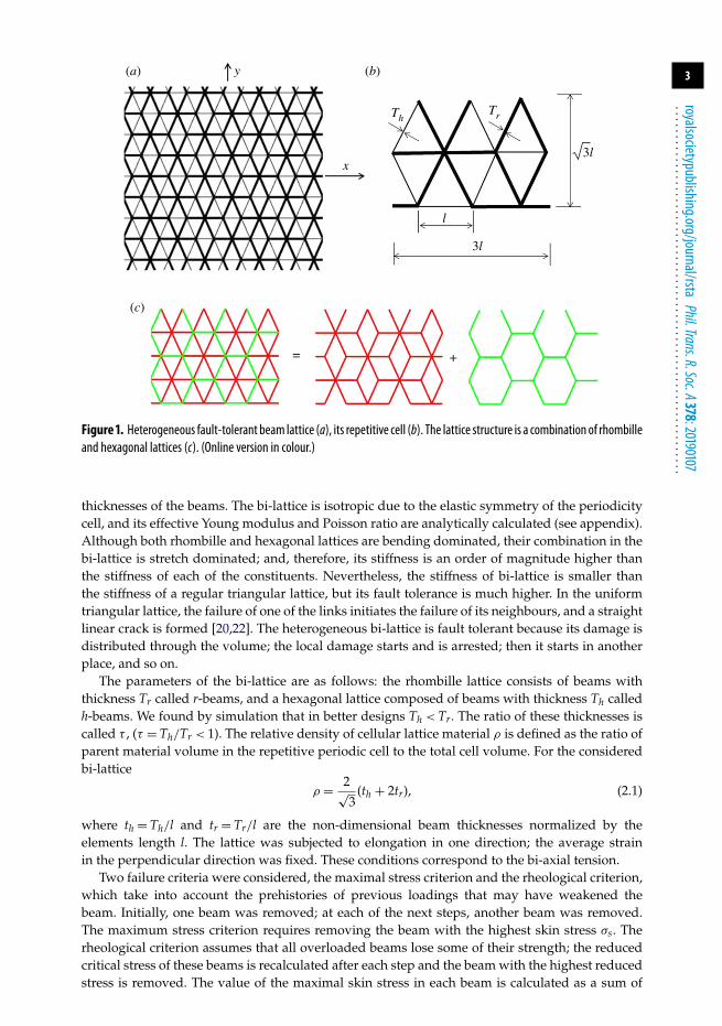
2. The theoretical result for the bi-axial tension of brittle latticeThe design of a heterogeneous brittle fault-tolerant lattice, which was found in [21] is presentedin figure 1. This lattice (bi-lattice) is a superposition of two basic lattices (figure 1c) with different
3
royalsocietypublishing.org/journal/rstaPhil.Trans.R.Soc.A378:20190107
................................................................
TrTh
x
l
3l
3l
y (b)(a)
(c)
= +
Figure 1. Heterogeneous fault-tolerant beam lattice (a), its repetitive cell (b). The lattice structure is a combination of rhombilleand hexagonal lattices (c). (Online version in colour.)
thicknesses of the beams. The bi-lattice is isotropic due to the elastic symmetry of the periodicitycell, and its effective Young modulus and Poisson ratio are analytically calculated (see appendix).Although both rhombille and hexagonal lattices are bending dominated, their combination in thebi-lattice is stretch dominated; and, therefore, its stiffness is an order of magnitude higher thanthe stiffness of each of the constituents. Nevertheless, the stiffness of bi-lattice is smaller thanthe stiffness of a regular triangular lattice, but its fault tolerance is much higher. In the uniformtriangular lattice, the failure of one of the links initiates the failure of its neighbours, and a straightlinear crack is formed [20,22]. The heterogeneous bi-lattice is fault tolerant because its damage isdistributed through the volume; the local damage starts and is arrested; then it starts in anotherplace, and so on.
The parameters of the bi-lattice are as follows: the rhombille lattice consists of beams withthickness Tr called r-beams, and a hexagonal lattice composed of beams with thickness Th calledh-beams. We found by simulation that in better designs Th < Tr. The ratio of these thicknesses iscalled τ , (τ = Th/Tr < 1). The relative density of cellular lattice material ρ is defined as the ratio ofparent material volume in the repetitive periodic cell to the total cell volume. For the consideredbi-lattice
ρ = 2√3
(th + 2tr), (2.1)
where th = Th/l and tr = Tr/l are the non-dimensional beam thicknesses normalized by theelements length l. The lattice was subjected to elongation in one direction; the average strainin the perpendicular direction was fixed. These conditions correspond to the bi-axial tension.
Two failure criteria were considered, the maximal stress criterion and the rheological criterion,which take into account the prehistories of previous loadings that may have weakened thebeam. Initially, one beam was removed; at each of the next steps, another beam was removed.The maximum stress criterion requires removing the beam with the highest skin stress σs. Therheological criterion assumes that all overloaded beams lose some of their strength; the reducedcritical stress of these beams is recalculated after each step and the beam with the highest reducedstress is removed. The value of the maximal skin stress in each beam is calculated as a sum of
4
royalsocietypublishing.org/journal/rstaPhil.Trans.R.Soc.A378:20190107
................................................................
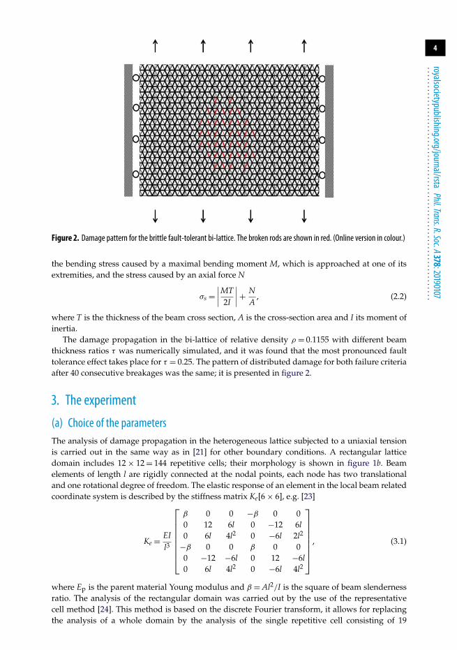
Figure 2. Damage pattern for the brittle fault-tolerant bi-lattice. The broken rods are shown in red. (Online version in colour.)
the bending stress caused by a maximal bending moment M, which is approached at one of itsextremities, and the stress caused by an axial force N
σs =∣∣∣∣MT2I
∣∣∣∣ + NA
, (2.2)
where T is the thickness of the beam cross section, A is the cross-section area and I its moment ofinertia.
The damage propagation in the bi-lattice of relative density ρ = 0.1155 with different beamthickness ratios τ was numerically simulated, and it was found that the most pronounced faulttolerance effect takes place for τ = 0.25. The pattern of distributed damage for both failure criteriaafter 40 consecutive breakages was the same; it is presented in figure 2.
3. The experiment
(a) Choice of the parametersThe analysis of damage propagation in the heterogeneous lattice subjected to a uniaxial tensionis carried out in the same way as in [21] for other boundary conditions. A rectangular latticedomain includes 12 × 12 = 144 repetitive cells; their morphology is shown in figure 1b. Beamelements of length l are rigidly connected at the nodal points, each node has two translationaland one rotational degree of freedom. The elastic response of an element in the local beam relatedcoordinate system is described by the stiffness matrix Ke[6 × 6], e.g. [23]
Ke = EIl3
⎡⎢⎢⎢⎢⎢⎢⎢⎣
β 0 0 −β 0 00 12 6l 0 −12 6l0 6l 4l2 0 −6l 2l2
−β 0 0 β 0 00 −12 −6l 0 12 −6l0 6l 4l2 0 −6l 4l2
⎤⎥⎥⎥⎥⎥⎥⎥⎦
, (3.1)
where Ep is the parent material Young modulus and β = Al2/I is the square of beam slendernessratio. The analysis of the rectangular domain was carried out by the use of the representativecell method [24]. This method is based on the discrete Fourier transform, it allows for replacingthe analysis of a whole domain by the analysis of the single repetitive cell consisting of 19
5
royalsocietypublishing.org/journal/rstaPhil.Trans.R.Soc.A378:20190107
................................................................
x
y
Dy
smax – smin
smin
Dx
(b)(a)
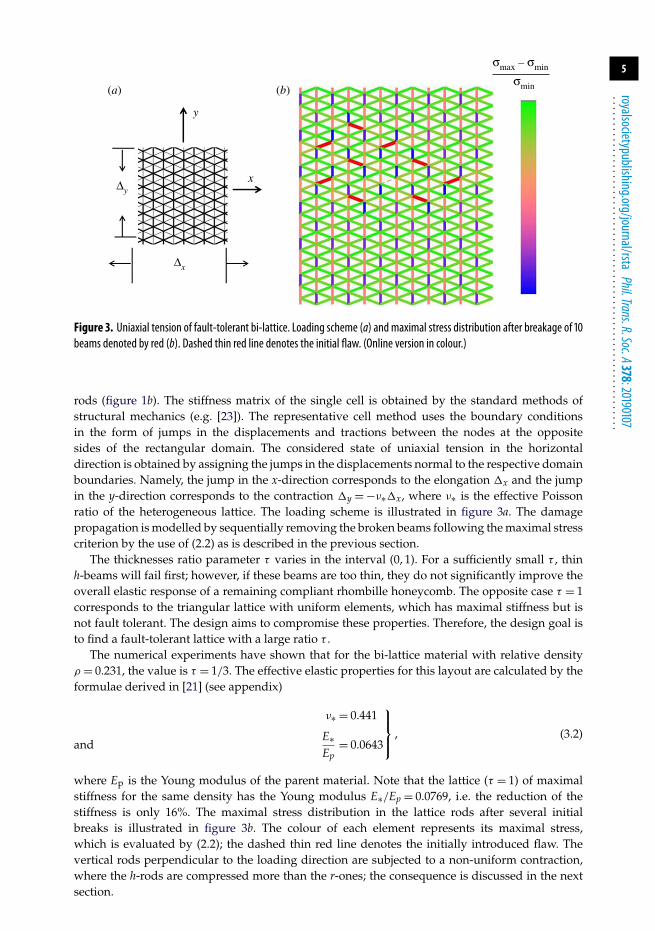
Figure 3. Uniaxial tension of fault-tolerant bi-lattice. Loading scheme (a) and maximal stress distribution after breakage of 10beams denoted by red (b). Dashed thin red line denotes the initial flaw. (Online version in colour.)
rods (figure 1b). The stiffness matrix of the single cell is obtained by the standard methods ofstructural mechanics (e.g. [23]). The representative cell method uses the boundary conditionsin the form of jumps in the displacements and tractions between the nodes at the oppositesides of the rectangular domain. The considered state of uniaxial tension in the horizontaldirection is obtained by assigning the jumps in the displacements normal to the respective domainboundaries. Namely, the jump in the x-direction corresponds to the elongation �x and the jumpin the y-direction corresponds to the contraction �y = −ν∗�x, where ν∗ is the effective Poissonratio of the heterogeneous lattice. The loading scheme is illustrated in figure 3a. The damagepropagation is modelled by sequentially removing the broken beams following the maximal stresscriterion by the use of (2.2) as is described in the previous section.
The thicknesses ratio parameter τ varies in the interval (0, 1). For a sufficiently small τ , thinh-beams will fail first; however, if these beams are too thin, they do not significantly improve theoverall elastic response of a remaining compliant rhombille honeycomb. The opposite case τ = 1corresponds to the triangular lattice with uniform elements, which has maximal stiffness but isnot fault tolerant. The design aims to compromise these properties. Therefore, the design goal isto find a fault-tolerant lattice with a large ratio τ .
The numerical experiments have shown that for the bi-lattice material with relative densityρ = 0.231, the value is τ = 1/3. The effective elastic properties for this layout are calculated by theformulae derived in [21] (see appendix)
ν∗ = 0.441
andE∗Ep
= 0.0643
⎫⎪⎬⎪⎭
, (3.2)
where Ep is the Young modulus of the parent material. Note that the lattice (τ = 1) of maximalstiffness for the same density has the Young modulus E∗/Ep = 0.0769, i.e. the reduction of thestiffness is only 16%. The maximal stress distribution in the lattice rods after several initialbreaks is illustrated in figure 3b. The colour of each element represents its maximal stress,which is evaluated by (2.2); the dashed thin red line denotes the initially introduced flaw. Thevertical rods perpendicular to the loading direction are subjected to a non-uniform contraction,where the h-rods are compressed more than the r-ones; the consequence is discussed in the nextsection.
6
royalsocietypublishing.org/journal/rstaPhil.Trans.R.Soc.A378:20190107
................................................................
0
0
5
10
15
20
25
30
stre
ss, M
Pa (
initi
al c
ross
sec
tion)
35
40
45
50
55
0.2epy0.4 0.6
type IV
strain (by CCD tracking)
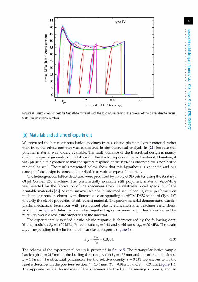
Figure 4. Uniaxial tension test for VeroWhite material with the loading/unloading. The colours of the curves denote severaltests. (Online version in colour.)
(b) Materials and scheme of experimentWe prepared the heterogeneous lattice specimen from a elastic–plastic polymer material ratherthan from the brittle one that was considered in the theoretical analysis in [21] because thispolymer material was widely available. The fault tolerance of the theoretical design is mainlydue to the special geometry of the lattice and the elastic response of parent material. Therefore, itwas plausible to hypothesize that the special response of the lattice is observed for a non-brittlematerial as well. The results presented below show that this hypothesis is validated and ourconcept of the design is robust and applicable to various types of materials.
The heterogeneous lattice structures were produced by a Polyjet 3D printer using the StratasysObjet Connex 260 machine. The commercially available stiff polymeric material VeroWhitewas selected for the fabrication of the specimens from the relatively broad spectrum of theprintable materials [25]. Several uniaxial tests with intermediate unloading were performed onthe homogeneous specimens with dimensions corresponding to ASTM D638 standard (Type IV)to verify the elastic properties of this parent material. The parent material demonstrates elastic–plastic mechanical behaviour with pronounced plastic elongation after reaching yield stress,as shown in figure 4. Intermediate unloading–loading cycles reveal slight hysteresis caused byrelatively weak viscoelastic properties of the material.
The experimentally verified elastic–plastic response is characterized by the following data:Young modulus Ep = 1650 MPa, Poisson ratio νp = 0.42 and yield stress σpy = 50 MPa. The strainεpy corresponding to the limit of the linear elastic response (figure 4) is
εpy = σpy
Ep= 0.0303. (3.3)
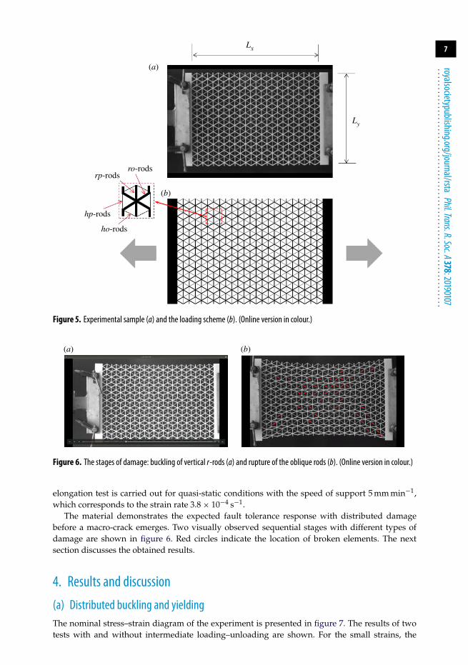
The scheme of the experimental set-up is presented in figure 5. The rectangular lattice samplehas length Lx = 217 mm in the loading direction, width Ly = 157 mm and out-of-plane thicknesslo = 1.5 mm. The structural parameters for the relative density ρ = 0.231 are chosen to fit theresults described in the previous section: l = 10.5 mm, Th = 0.94 mm and Tr = 0.3 mm (figure 1b).The opposite vertical boundaries of the specimen are fixed at the moving supports, and an
7
royalsocietypublishing.org/journal/rstaPhil.Trans.R.Soc.A378:20190107
................................................................
Ly
ro-rodsrp-rods
hp-rods
ho-rods
Lx
(b)
(a)
Figure 5. Experimental sample (a) and the loading scheme (b). (Online version in colour.)
(b)(a)
Figure 6. The stages of damage: buckling of vertical r-rods (a) and rupture of the oblique rods (b). (Online version in colour.)
elongation test is carried out for quasi-static conditions with the speed of support 5 mm min−1,which corresponds to the strain rate 3.8 × 10⁻⁴ s−1.
The material demonstrates the expected fault tolerance response with distributed damagebefore a macro-crack emerges. Two visually observed sequential stages with different types ofdamage are shown in figure 6. Red circles indicate the location of broken elements. The nextsection discusses the obtained results.
4. Results and discussion
(a) Distributed buckling and yieldingThe nominal stress–strain diagram of the experiment is presented in figure 7. The results of twotests with and without intermediate loading–unloading are shown. For the small strains, the
8
royalsocietypublishing.org/journal/rstaPhil.Trans.R.Soc.A378:20190107
................................................................
121086–ex (%)
–(3)ex–(2)ex
–(1)ex
2 400
0.01
0.02
0.03
0.04
–sxspy
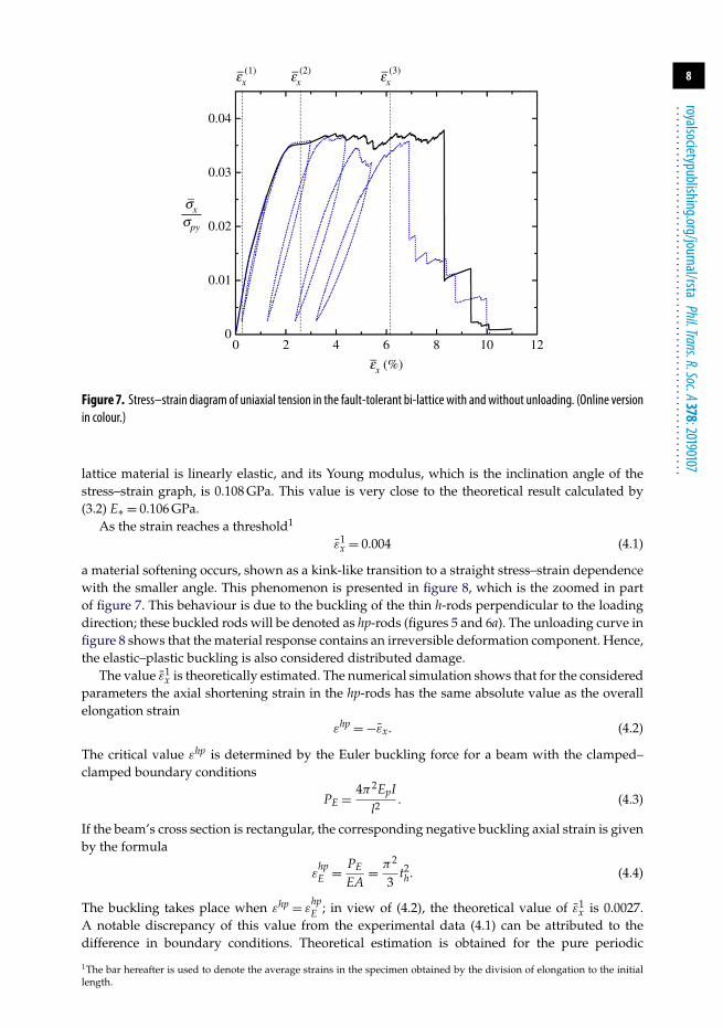
Figure 7. Stress–strain diagram of uniaxial tension in the fault-tolerant bi-lattice with and without unloading. (Online versionin colour.)
lattice material is linearly elastic, and its Young modulus, which is the inclination angle of thestress–strain graph, is 0.108 GPa. This value is very close to the theoretical result calculated by(3.2) E∗ = 0.106 GPa.
As the strain reaches a threshold1
ε̄1x = 0.004 (4.1)
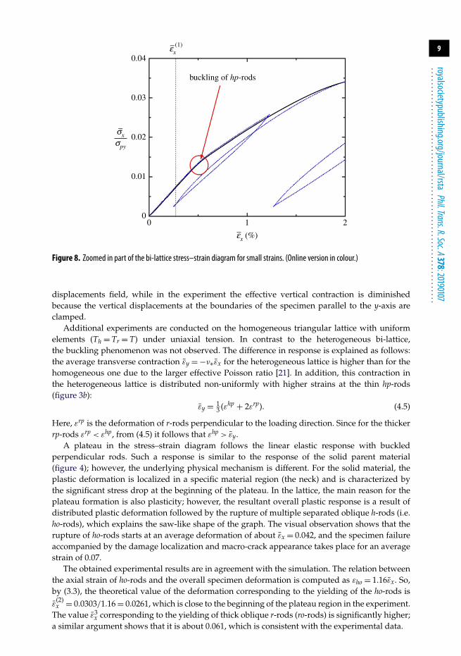
a material softening occurs, shown as a kink-like transition to a straight stress–strain dependencewith the smaller angle. This phenomenon is presented in figure 8, which is the zoomed in partof figure 7. This behaviour is due to the buckling of the thin h-rods perpendicular to the loadingdirection; these buckled rods will be denoted as hp-rods (figures 5 and 6a). The unloading curve infigure 8 shows that the material response contains an irreversible deformation component. Hence,the elastic–plastic buckling is also considered distributed damage.
The value ε̄1x is theoretically estimated. The numerical simulation shows that for the considered
parameters the axial shortening strain in the hp-rods has the same absolute value as the overallelongation strain
εhp = −ε̄x. (4.2)
The critical value εhp is determined by the Euler buckling force for a beam with the clamped–clamped boundary conditions
PE = 4π2EpI
l2. (4.3)
If the beam’s cross section is rectangular, the corresponding negative buckling axial strain is givenby the formula
εhpE = PE
EA= π2
3t2h. (4.4)
The buckling takes place when εhp = εhpE ; in view of (4.2), the theoretical value of ε̄1
x is 0.0027.A notable discrepancy of this value from the experimental data (4.1) can be attributed to thedifference in boundary conditions. Theoretical estimation is obtained for the pure periodic
1The bar hereafter is used to denote the average strains in the specimen obtained by the division of elongation to the initiallength.
9
royalsocietypublishing.org/journal/rstaPhil.Trans.R.Soc.A378:20190107
................................................................
–ex (%)
–(1)ex
–sxspy
0
0.01
0.02
0.03
buckling of hp-rods
0.04
1 20
Figure 8. Zoomed in part of the bi-lattice stress–strain diagram for small strains. (Online version in colour.)
displacements field, while in the experiment the effective vertical contraction is diminishedbecause the vertical displacements at the boundaries of the specimen parallel to the y-axis areclamped.
Additional experiments are conducted on the homogeneous triangular lattice with uniformelements (Th = Tr = T) under uniaxial tension. In contrast to the heterogeneous bi-lattice,the buckling phenomenon was not observed. The difference in response is explained as follows:the average transverse contraction ε̄y = −ν∗ε̄x for the heterogeneous lattice is higher than for thehomogeneous one due to the larger effective Poisson ratio [21]. In addition, this contraction inthe heterogeneous lattice is distributed non-uniformly with higher strains at the thin hp-rods(figure 3b):
ε̄y = 13 (εhp + 2εrp). (4.5)
Here, εrp is the deformation of r-rods perpendicular to the loading direction. Since for the thickerrp-rods εrp < εhp, from (4.5) it follows that εhp > ε̄y.
A plateau in the stress–strain diagram follows the linear elastic response with buckledperpendicular rods. Such a response is similar to the response of the solid parent material(figure 4); however, the underlying physical mechanism is different. For the solid material, theplastic deformation is localized in a specific material region (the neck) and is characterized bythe significant stress drop at the beginning of the plateau. In the lattice, the main reason for theplateau formation is also plasticity; however, the resultant overall plastic response is a result ofdistributed plastic deformation followed by the rupture of multiple separated oblique h-rods (i.e.ho-rods), which explains the saw-like shape of the graph. The visual observation shows that therupture of ho-rods starts at an average deformation of about ε̄x = 0.042, and the specimen failureaccompanied by the damage localization and macro-crack appearance takes place for an averagestrain of 0.07.
The obtained experimental results are in agreement with the simulation. The relation betweenthe axial strain of ho-rods and the overall specimen deformation is computed as εho = 1.16ε̄x. So,by (3.3), the theoretical value of the deformation corresponding to the yielding of the ho-rods isε̄
(2)x = 0.0303/1.16 = 0.0261, which is close to the beginning of the plateau region in the experiment.
The value ε̄3x corresponding to the yielding of thick oblique r-rods (ro-rods) is significantly higher;
a similar argument shows that it is about 0.061, which is consistent with the experimental data.
10
royalsocietypublishing.org/journal/rstaPhil.Trans.R.Soc.A378:20190107
................................................................
–ex (%)
–sxspy
0
0.02
0.04
0.06
0.08
0.10
0.12
triangular
rhombille
bi-lattice
8 162 4 6 10 12 14
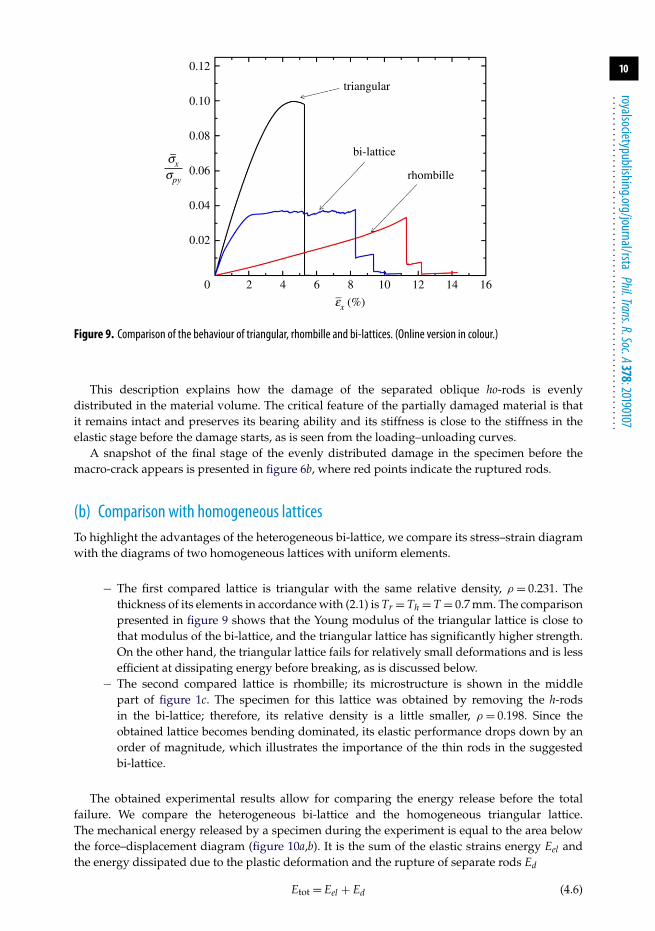
Figure 9. Comparison of the behaviour of triangular, rhombille and bi-lattices. (Online version in colour.)
This description explains how the damage of the separated oblique ho-rods is evenlydistributed in the material volume. The critical feature of the partially damaged material is thatit remains intact and preserves its bearing ability and its stiffness is close to the stiffness in theelastic stage before the damage starts, as is seen from the loading–unloading curves.
A snapshot of the final stage of the evenly distributed damage in the specimen before themacro-crack appears is presented in figure 6b, where red points indicate the ruptured rods.
(b) Comparison with homogeneous latticesTo highlight the advantages of the heterogeneous bi-lattice, we compare its stress–strain diagramwith the diagrams of two homogeneous lattices with uniform elements.
− The first compared lattice is triangular with the same relative density, ρ = 0.231. Thethickness of its elements in accordance with (2.1) is Tr = Th = T = 0.7 mm. The comparisonpresented in figure 9 shows that the Young modulus of the triangular lattice is close tothat modulus of the bi-lattice, and the triangular lattice has significantly higher strength.On the other hand, the triangular lattice fails for relatively small deformations and is lessefficient at dissipating energy before breaking, as is discussed below.
− The second compared lattice is rhombille; its microstructure is shown in the middlepart of figure 1c. The specimen for this lattice was obtained by removing the h-rodsin the bi-lattice; therefore, its relative density is a little smaller, ρ = 0.198. Since theobtained lattice becomes bending dominated, its elastic performance drops down by anorder of magnitude, which illustrates the importance of the thin rods in the suggestedbi-lattice.
The obtained experimental results allow for comparing the energy release before the totalfailure. We compare the heterogeneous bi-lattice and the homogeneous triangular lattice.The mechanical energy released by a specimen during the experiment is equal to the area belowthe force–displacement diagram (figure 10a,b). It is the sum of the elastic strains energy Eel andthe energy dissipated due to the plastic deformation and the rupture of separate rods Ed
Etot = Eel + Ed (4.6)
11
royalsocietypublishing.org/journal/rstaPhil.Trans.R.Soc.A378:20190107
................................................................
3025displacement (mm)
displacement (mm)
20151050
200
400
600
800
forc
e (N
)
1000
1200
0
200
400
600
800
forc
e (N
)
forc
e (N
)
1000
1200
3025displacement (mm)
Fcr
Ed Eel
DeDd
2015105
(b)(a)
(c)
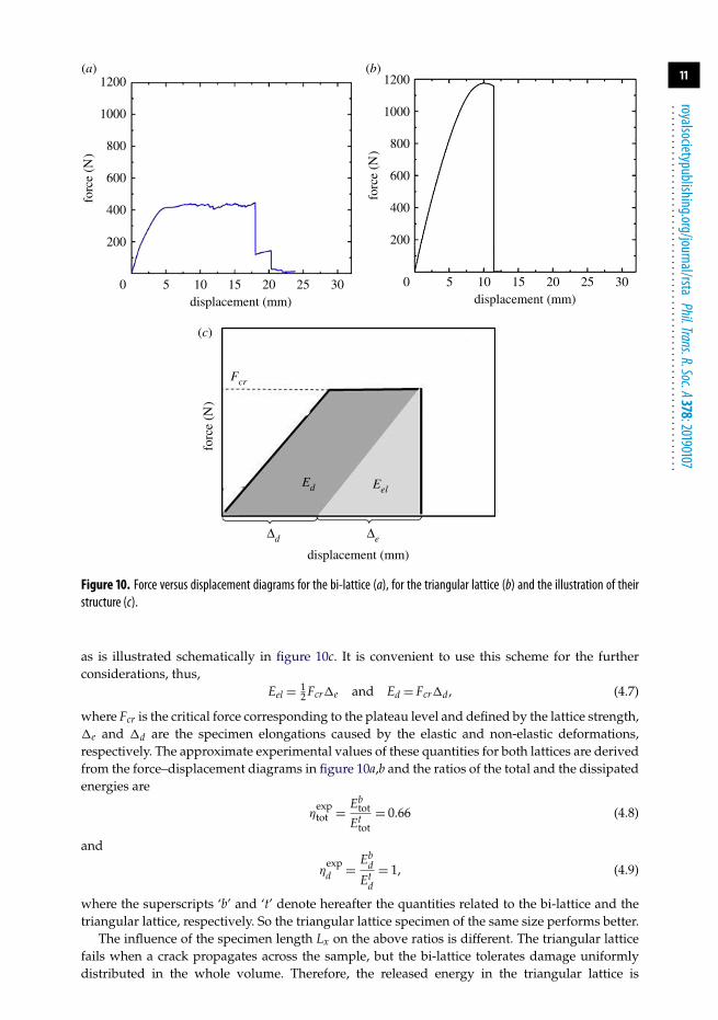
Figure 10. Force versus displacement diagrams for the bi-lattice (a), for the triangular lattice (b) and the illustration of theirstructure (c).
as is illustrated schematically in figure 10c. It is convenient to use this scheme for the furtherconsiderations, thus,
Eel = 12 Fcr�e and Ed = Fcr�d, (4.7)
where Fcr is the critical force corresponding to the plateau level and defined by the lattice strength,�e and �d are the specimen elongations caused by the elastic and non-elastic deformations,respectively. The approximate experimental values of these quantities for both lattices are derivedfrom the force–displacement diagrams in figure 10a,b and the ratios of the total and the dissipatedenergies are
ηexptot = Eb
tot
Ettot
= 0.66 (4.8)
and
ηexpd = Eb
d
Etd
= 1, (4.9)
where the superscripts ‘b’ and ‘t’ denote hereafter the quantities related to the bi-lattice and thetriangular lattice, respectively. So the triangular lattice specimen of the same size performs better.
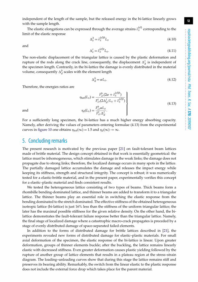
The influence of the specimen length Lx on the above ratios is different. The triangular latticefails when a crack propagates across the sample, but the bi-lattice tolerates damage uniformlydistributed in the whole volume. Therefore, the released energy in the triangular lattice is
12
royalsocietypublishing.org/journal/rstaPhil.Trans.R.Soc.A378:20190107
................................................................
independent of the length of the sample, but the released energy in the bi-lattice linearly growswith the sample length.
The elastic elongations can be expressed through the average strains ε̄(el)x corresponding to the
limit of the elastic response�b
e = ε̄(el)bx Lx (4.10)
and�t
e = ε̄(el)tx Lx. (4.11)
The non-elastic displacement of the triangular lattice is caused by the plastic deformation andrupture of the rods along the crack line, consequently, the displacement �t
d is independent ofthe specimen length. Contrarily, in the bi-lattice the damage is evenly distributed in the materialvolume, consequently �b
d scales with the element length
�bd = αLx. (4.12)
Therefore, the energies ratios are
ηtot(Lx) = Fbcr(2α + ε̄
(el)bx )
Ftcr(2�t
d/Lx + ε̄(el)tx )
and ηd(Lx) = FbcrαLx
Ftcr�
td
.
⎫⎪⎪⎪⎪⎪⎬⎪⎪⎪⎪⎪⎭
(4.13)
For a sufficiently long specimen, the bi-lattice has a much higher energy absorbing capacity.Namely, after deriving the values of parameters entering formulae (4.13) from the experimentalcurves in figure 10 one obtains ηtot(∞) = 1.5 and ηd(∞) → ∞.
5. Concluding remarksThe present research is motivated by the previous paper [21] on fault-tolerant beam latticesmade of brittle material. The design concept obtained in that work is essentially geometrical: thelattice must be inhomogeneous, which stimulates damage in the weak links; the damage does notpropagate due to strong links; therefore, the localized damage occurs in many spots in the lattice.The partially damaged lattice accumulates the damage and releases the impact energy whilekeeping its stiffness, strength and structural integrity. The concept is robust; it was numericallytested for a elastic-brittle material, and in the present paper, experimentally verifies this conceptfor a elastic–plastic material and finds consistent results.
We tested the heterogeneous lattice consisting of two types of beams. Thick beams form arhombille bending-dominated lattice, and thinner beams are added to transform it to a triangularlattice. The thinner beams play an essential role in switching the elastic response from thebending dominated to the stretch dominated. The effective stiffness of the obtained heterogeneousisotropic lattice (bi-lattice) is just 16% less than the stiffness of the uniform triangular lattice; thelater has the maximal possible stiffness for the given relative density. On the other hand, the bi-lattice demonstrates the fault-tolerant failure response better than the triangular lattice. Namely,the final stage of localized damage where a catastrophic macro-crack propagates is preceded by astage of evenly distributed damage of space-separated failed elements.
In addition to the forms of distributed damage for brittle lattices described in [21], theexperiments revealed new forms of distributed damage for elastic–plastic materials. For smallaxial deformation of the specimen, the elastic response of the bi-lattice is linear. Upon greaterdeformation, groups of thinner elements buckle; after the buckling, the lattice remains linearlyelastic with decreased stiffness. Even greater deformation causes plastic yielding followed by therupture of another group of lattice elements that results in a plateau region at the stress–straindiagram. The loading–unloading curves show that during this stage the lattice remains stiff andpreserves its bearing ability. Remarkably, the switch from the linear elastic to the plastic responsedoes not include the external force drop which takes place for the parent material.
13
royalsocietypublishing.org/journal/rstaPhil.Trans.R.Soc.A378:20190107
................................................................
The comparison of the failure of the fault-tolerant inhomogeneous bi-lattice and thehomogeneous triangular one shows that the bi-lattice is preferable from the total energyrelease point of view thanks to the extended stage of evenly distributed damage. Its excellentenergy absorption capacity becomes pronounced for the energy irreversibly dissipated by plasticdeformation and rupture of lattice elements. Note that the heterogeneous microstructure of theconsidered bi-lattice with thin h-beams surrounded by thicker r-beams is a discrete analogue ofthe biocalcite-like composite, characterized by soft inclusions embedded in a stiff matrix. Theadvantage of such a microstructure for increasing the defect tolerance ability of a composite inthe framework of fracture problems was emphasized in [26].
This work investigates distributed damage in fault-tolerant heterogeneous latticesexperimentally. The considered bi-lattice is less stiff and less strong than uniform triangular one,but it remains intact for the relatively high deformations, its damage is not catastrophic, and itpossesses an excellent energy absorption capacity. Future research will investigate the design ofthree-dimensional fault-tolerant trusses.
Data accessibility. This article has no additional data.Authors’ contributions. V.S. and S.R. prepared samples and conducted experiments. M.R. and A.C. developed atheory of fault-tolerant lattices and found their optimal parameters; M.R. conducted numerical simulation.Competing interests. We declare we have no competing interests.Funding. The authors gratefully acknowledge support by DMS, National Science Foundation, award no.1515125 and by Israel Science Foundation, grant no. 1494/16. Stephan Rudykh gratefully acknowledges thesupport of Grainger Institute for Engineering and the University of Wisconsin–Madison.
Appendix AThe effective elastic moduli of the heterogeneous bi-lattice with the microstructure shown infigure 1b are given by the following formulae, see [21]
ν∗ = 4t2r ((1 − t2
r ) + 4t2h((1 − t2
h) + t3r th(1 − 9t2
h) + trth(1 + 7t2h)
P1(tr, th)(A 1)
andE∗Ep
= 2(2tr + th)(8t4r + 9trth + t3
r th + trt3h + 9t3
r t3h + 8t4
h)√3P1(tr, th)
, (A 2)
whereth = Th/l, tr = Tr/l
andP1(tr, th) = 4t2
r P2(tr) + trth(19 + 9t2h) + (3t3
r + 4th2)P2(th), P2(t) = 1 + 3t2.
References1. Reilly GC, Currey JD. 1999 The development of microcracking and failure in bone depends
on the loading mode to which it is adapted. J. Exp. Biol. 202, 543–552.2. Ziopos P, Currey JD. 1994 The extent of microcracking and the morphology of microcracks in
damaged bone. J. Mater. Sci. 29, 978–986. (doi:10.1007/BF00351420)3. Barthelat F. 2007 Biomimetics for next generation materials. Phil. Trans. R. Soc. A 365, 2907–
2919. (doi:10.1098/rsta.2007.0006)4. Currey J. 2001 Sacrificial bonds heal bone. Nature 414, 699. (doi:10.1038/414699a)5. Thompson JB, Kindt JH, Drake BHansma, Hansma PK. 2001 Bone indentation recovery time
correlates with bond reforming time. Nature 414, 773–776. (doi:10.1038/414773a)6. Slesarenko V, Kazarinov N, Rudykh S. 2017 Distinct failure modes in bio-inspired 3D-
printed staggered composites under non-aligned loadings. Smart Mater. Struct. 26, 035053.(doi:10.1088/1361-665X/aa59eb)
7. Barthelat F. 2014 Designing nacre-like materials for simultaneous stiffness, strength andtoughness: optimum materials, composition, microstructure and size. J. Mech. Phys. Solids 73,22–37. (doi:10.1016/j.jmps.2014.08.008)
14
royalsocietypublishing.org/journal/rstaPhil.Trans.R.Soc.A378:20190107
................................................................
8. Slesarenko V, Volokh KY, Aboudi J, Rudykh S. 2017 Understanding the strength of bioinspiredsoft composites. Int. J. Mech. Sci. 131-132, 171–178. (doi:10.1016/j.ijmecsci.2017.06.054)
9. Kothari K, Hu Y, Gupta S, Elbanna A. 2018 Mechanical response of two-dimensional polymernetworks: role of topology, rate dependence, and damage accumulation. J. Appl. Mech. 85,031008-1–031008-11. (doi:10.1115/1.4038883)
10. McGugan M, Pereira G, Sorensen BF, Toftegaard H, Branner K. 2015 Damage tolerance andstructural monitoring for wind turbine blades open access. Phil. Trans. R. Soc. A 373, 20140077.(doi:10.1098/rsta.2014.0077)
11. Worden K, Farrar CR. 2007 An introduction to structural health monitoring. Phil. Trans. R. Soc.A 365, 303–315. (doi:10.1098/rsta.2006.1938)
12. Cherkaev A, Slepyan L. 1995 Waiting element structures and stability under extension. Int. J.Damage Mech. 4, 58–82. (doi:10.1177/105678959500400104)
13. Cherkaev A, Cherkaev E, Slepyan L. 2005 Transition waves in bistable structures: I.Delocalization of damage. J. Mech. Phys. Solids 53, 383–405. (doi:10.1016/j.jmps.2004.08.002)
14. Slepyan L, Cherkaev A, Cherkaev E. 2005 Transition waves in bistable structures: II.Analytical solution, wave speed, and energy dissipation. J. Mech. Phys. Solids 53, 407–436.(doi:10.1016/j.jmps.2004.08.001)
15. Cherkaev A, Zhornitskaya L. 2004 Dynamics of damage in two-dimensional structures withwaiting links. In Asymptotics, singularities and homogenisation in problems of mechanics (ed. ABMovchan), pp. 273–284. Dordrecht, the Netherlands: Kluwer.
16. Cherkaev A, Vinogradov V, Leelavanichkul S. 2006 The waves of damage in elastic-plastic lattices with waiting links: design and simulation. Mech. Mater. 38, 748–756.(doi:10.1016/j.mechmat.2005.06.017)
17. Leelavanichkul S, Cherkaev A, Adams D, Solzbacher F. 2009 Energy absorption of a helicoidalbistable structure. J. Mech. Mater. Struct. 5, 305–321. (doi:10.2140/jomms)
18. Cherkaev A, Cherkaev E, Leelavanichkul S. 2011 Principle of optimization of structuresagainst an impact. J. Phys.: Conf. Ser. 319, 1–16. (https://doi.org/10.1088/1742-6596/319/1/012021)
19. Cherkaev A, Leelavanichkul S. 2012 An impact protective structure with bistable links. Int. J.Damage Mech. 21, 697–711. (doi:10.1177/1056789511410458)
20. Cherkaev A, Ryvkin M. 2019 Damage propagation in 2d beam lattices: 1. Uncertainty andassumptions. Arch. Appl. Mech. 89, 485–501. (doi:10.1007/s00419-018-1429-z)
21. Cherkaev A, Ryvkin M. 2019 Damage propagation in 2d beam lattices: 2. Design of anisotropic fault-tolerant lattice. Arch. Appl. Mech. 89, 503–519. (doi:10.1007/s00419-018-1428-0)
22. Lipperman P, Ryvkin M, Fuchs MB. 2007 Nucleation of cracks in two-dimensional periodiccellular materials. Comput. Mech. 39, 127–139. (doi:10.1007/s00466-005-0014-9)
23. Fuchs MB. 2016 Structures and their analysis. Switzerland: Springer International Publishing.24. Ryvkin M, Fuchs MB, Nuller B. 1999 Optimal design of infinite repetitive structures. Struct.
Optim. 18, 202–209. (doi:10.1007/BF01195995)25. Slesarenko V. 2018 Towards mechanical characterization of soft digital materials for
multimaterial 3D-printing. Int. J. Eng. Sci. 123, 62–72. (doi:10.1016/j.ijengsci.2017.11.011)26. Sen D, Buehler MJ. 2011 Structural hierarchies define toughness and defect- tolerance
despite simple and mechanically inferior brittle building blocks. Sci. Rep. (Nature) 35, 1–15.(doi:10.1038/srep00035)