fec26 field equipment controllers installation...
TRANSCRIPT

FEC26 Field Equipment Controllers Installation InstructionsMS-FEC2611-x, MS-FEC2621-x, MS-FEC2611-xET
Part No. 24-10143-144, Rev. LIssued November 2017
Refer to the QuickLIT website for the most up-to-date version of this document.
ApplicationThe FEC26 controllers are part of theMetasys® systemField Equipment Controller (FEC) family. Thesecontrollers run pre-engineered and user-programmedapplications and provide the inputs and outputs requiredto monitor and control a wide variety of HVAC and otherfacility equipment.
The FEC controllers operate on an RS-485 BACnet®Master-Slave/Token-Passing (MS/TP) Bus as BACnetApplication Specific Controllers (B-ASCs) and integrateinto Johnson Controls® and third-party BACnet systems.
The FEC26 controller is available with or without anintegral LCD and push button user interface.
Important: In Metasys system smoke controlapplications, use only the MS-FEC2611-0Uand MS-FEC2621-0U at Metasys Release8.1 that are UL 864 UUKL/UUKLC 10thEdition Smoke Control Listed. ForMetasyssystem smoke control applications, youmust refer to the Metasys System UL 864UUKL Tenth Edition Smoke Control SystemTechnical Bulletin (LIT-12012487) fordetailed requirements and procedures forinstalling, commissioning, and operating UL864 UUKL ListedMetasys system devices.The UL 864 UUKL listing for Smoke ControlEquipment is voided if (1) you do not usethe required software tools at the requiredversions; or (2) you do not meet therequirements or do not follow theprocedures as documented in the MetasysSystemUL 864 UUKL Tenth Edition SmokeControl System Technical Bulletin(LIT-12012487).
Switchable CommunicationsProtocolsBy default, theMetasys® system FEC Family Controllersand network sensors communicate using either thestandard BACnet protocol based on the ANSI/ASHRAE135-2004, or the BACnet/IP protocol.
The BACnet protocol is a standard for ANSI, ASHRAE,and the International Standards Organization (ISO) forbuilding controls.
FEC, VMA16, VMA18, andmost IOM field controllers areBTL-listed as BACnet Application Specific Controllers(B-ASCs). FAC Field Controllers and the VMA1930 FieldController are BTL-listed as BACnet Advanced ApplicationControllers (B-AACs). The NS Series Sensors areBTL-listed as BACnet Smart Sensors (B-SSs).
Release 10.1 and later of the Controller ConfigurationTool (CCT) can be used to switch the Field Buscommunications protocol in supported FEC Family FieldControllers to be either the standard BACnet MS/TP orthe N2 protocol. All new controllers use BACnet MS/TPas the default communications protocol. Switchablecommunications protocols in the MS/TP models providea cost-effective upgrade and modernization path forcustomers with existing N2 controllers.
The N2-capable FEC Family Controllers can be used asfunctional replacements for legacy N2 controllers. TheN2-capable FEC Family Controllers:• have the input and output (I/O) quantities and
characteristics of the FEC Family Controllers• must be programmed with CCT, which has similar,
but not identical programming capabilities asHVACPro, GX9100, GPL, and other legacy tools
• support SA Bus devices• support WRZ wireless sensors from the controller
using the WRZ-7860 receiver (most models)• are available in Buy American versions (most models)• are listed for UL864 UUKL/UUKLC (some models).
N2 is supported as part of theMetasys® Tenth Editionlisting for Smoke Control System Equipment. Fordetails, refer to the Metasys System UL 864 10thEdition UUKL/ORD-C100-13 UUKLC Smoke ControlSystem Technical Bulletin (LIT-12012487).
The N2-capable controllers:• do not support Zone Bus (for example, TMZ sensors
and M100 actuators) or XT-Bus (System 91) devices(for example, XT, XTM, and XP modules)
• do not support a wireless connection to the N2 bus• do not support NxE passthrough
1FEC26 Field Equipment Controllers Installation Instructions

North American EmissionsCompliance
CanadaThis Class (A) digital apparatus meets all therequirements of the Canadian Interference-CausingEquipment Regulations.
Cet appareil numérique de la Classe (A) respecte toutesles exigences du Règlement sur le matériel brouilleurdu Canada.
United StatesThis equipment has been tested and found to complywith the limits for a Class A digital device pursuant toPart 15 of the FCC Rules. These limits are designed toprovide reasonable protection against harmfulinterference when this equipment is operated in acommercial environment. This equipment generates,uses, and can radiate radio frequency energy and, if notinstalled and used in accordance with the instructionmanual, may cause harmful interference to radiocommunications. Operation of this equipment in aresidential areamay cause harmful interference, in whichcase the users will be required to correct the interferenceat their own expense.
InstallationObserve these guidelines when installing a field controller:
• Transport the controller in the original container tominimize vibration and shock damage.
• Verify that all parts shipped with the controller.• Do not drop the controller or subject it to physical
shock.
Parts Included• one field controller with removable terminal blocks
(Power, SA bus, and FC bus are removable)• one installation instructions sheet
Materials and Special Tools Needed• three fasteners appropriate for the mounting surface
(M4 screws or #8 screws)• one 20 cm (8 in.) or longer piece of 35 mm DIN rail
and appropriate hardware for DIN rail mount (only)• small straight-blade screwdriver for securing wires in
the terminal blocks
MountingObserve these guidelines when mounting a fieldcontroller:
• Ensure the mounting surface can support thecontroller, DIN rail, and any user-supplied enclosure.
• Mount the controller horizontally on 35 mm DIN railwhenever possible.
• Mount the controller in the proper mounting position(see Figure 1).
• Mount the controller on a hard, even surfacewhenever possible in wall-mount applications.
• Use shims or washers to mount the controller securelyand evenly on the mounting surface.
• Mount the controller in an area free of corrosivevapors and observe the Ambient Conditionsrequirements (see Table 11).
• Provide for sufficient space around the controller forcable and wire connections for easy cover removaland good ventilation through the controller (50 mm[2 in.] minimum on the top, bottom, and front of thecontroller).
• Do not mount the controller on surfaces prone tovibration, such as duct work.
• Do not mount the controller in areas whereelectromagnetic emissions from other devices orwiring can interfere with controller communication.
Observe these additional guidelines when mounting afield controller in a panel or enclosure:
• Mount the controller so that the enclosure walls donot obstruct cover removal or ventilation through thecontroller.
• Mount the controller so that the power transformerand other devices do not radiate excessive heat tothe controller.
• Do not install the controller in an airtight enclosure.
Figure 1: Field Controller Mounting Positions
2FEC26 Field Equipment Controllers Installation Instructions

DIN Rail Mount ApplicationsMounting the field controller horizontal on 35 mmDIN railis the preferred mounting method.
To mount a controller on 35 mm DIN rail:
1. Securely mount a 20 cm (8 in.) or longer section of35 mm DIN rail horizontal and centered in theappropriate location so that the controller mounts inthe horizontal position shown in Figure 1.
2. Pull the two bottom mounting clips outward from thecontroller to the extended position.
3. Hang the controller on the DIN rail by the hooks atthe top of the (DIN rail) channel on the back of thecontroller(see Figure 2), and position the controllersnugly against the DIN rail.
4. Push the bottommounting clips inward (up) to securethe controller on the DIN rail.
To remove the controller from the DIN rail, pull thebottom mounting clips out to the extended positionand carefully lift the controller off the DIN rail.
Wall Mount ApplicationsTo mount a field controller directly on a wall or other flatvertical surface:
1. Pull the two bottom mounting clips outward andensure they are locked in the extended position asshown in Figure 2.
2. Mark the mounting hole locations on the wall usingthe dimensions in Figure 2 and one of the mountpositions shown in Figure 1. Or hold the controller up
to the wall or surface in a proper mount position andmark the hole locations through the mounting clips.
3. Drill holes in the wall or surface at the markedlocations, and insert appropriate wall anchors in theholes (if necessary).
4. Hold the controller in place, and insert the screwsthrough the mounting clips and into the holes (oranchors). Carefully tighten all of the screws.
Important: Do not overtighten themounting screws.Overtightening the screwsmay damagethe mounting clips.
Figure 2: Back of Controller Showing ExtendedMounting Clips, DIN Rail Channel, and Mounting
Dimensions, mm (in.)
3FEC26 Field Equipment Controllers Installation Instructions

Figure 3: FEC2621 Physical Features
Table 1: FEC2621 Physical FeaturesPhysical Feature: Description and ReferencesCalloutBinary Output (BO) Source Power Selection Jumper Pin Blocks, 3 – BO Jumper Pin Blocks. See Table 4 for moreinformation.
1
Device Address DIP Switch Block. See Setting the Device Addresses for more information.2
Mounting Clip. See Mounting for more information.3
Configurable Output (COs) Terminal Blocks. See Table 4 for more information.4
Analog Outputs (AOs) Terminal Block. See Table 4 for more information.5
24 VAC, Class 2 Supply Power Terminal Block. See Table 6 for more information.6
Cover Lift Tab (One of Two). See Removing the Controller Cover for more information.7
Display Navigation Buttons. See Setting Up an Integral or Local Display.
Note: Not available on all FEC models.
8
Liquid Crystal Display (LCD) Display Area
Note: Not available on all FEC models.
9
Field Controller (FC) Bus Terminal Block. (See FC Bus Terminal Block.)10
Sensor Actuator (SA) Bus Terminal Block. (See SA Bus Terminal Block.)11
Sensor Actuator (SA) Bus (RJ-12 6-pin Modular Jack). See Sensor Port.12
Binary Input (BI) Terminal Block, 2 – Binary Inputs. See Table 4 for more information.13
Universal Input (UI) Terminal Blocks, 6 – Universal Inputs. See Table 4 for more information.14
LED Status Indicators. See Table 9 for more information.15
Field Controller (FC) Bus Port (RJ-12 6-pin Modular Jack). See FC Bus Port for more information.16
Binary Output (BO) Terminal Blocks. See Table 4.17
4FEC26 Field Equipment Controllers Installation Instructions

Wiring
Risk of Electric Shock: Disconnect the power supplybefore making electrical connections to avoid electricshock.
Mise En Garde: Risque de décharge électrique:Débrancher l'alimentation avant de réaliser toutraccordement électrique afin d'éviter tout risque dedécharge électrique.
Risk of Property Damage: Do not apply power to thesystem before checking all wiring connections. Shortcircuited or improperly connected wires may result inpermanent damage to the equipment.
Mise En Garde: Risque de dégâts matériels: Ne pasmettre le système sous tension avant d'avoir vérifié tousles raccords de câblage. Des fils formant un court-circuitou connectés de façon incorrecte risquentd'endommager irrémédiablement l'équipement.
Important: Do not exceed the controller electricalratings. Exceeding controller electricalratings can result in permanent damage tothe controller and void any warranty.
Important: Use copper conductors only. Make all wiringin accordance with local, national, andregional regulations.
Important: Electrostatic discharge can damagecontroller components. Use properelectrostatic discharge precautions duringinstallation, setup, and servicing to avoiddamaging the controller.
For detailed information on configuring and wiring anMS/TP Bus, FC bus, and SA bus, refer to the MS/TPCommunications Bus Technical Bulletin (LIT-12011034).
Terminal Blocks and Bus PortsSee Figure 3 for terminal block and bus port locations onthe controller. Observe the following guidelines whenwiring a controller.
Input and Output Terminal BlocksAll of the fixed input terminal blocks are mounted on thebottom of the controller and the output terminal blocksare mounted on the top of the controller. See Table 4 formore information about I/O terminal functions,requirements, and ratings.
FC Bus Terminal BlockThe FC Bus terminal block is a blue, removable,4-terminal plug that fits into a board-mounted jack.
Wire the removable FC bus terminal block plugs on thecontroller, and other controllers in a daisy-chainconfiguration using 3-wire twisted, shielded cable asshown below. See Table 6 for more information.
Figure 4: FC Bus Terminal Block Wiring
Note: The FC bus Shield (SHLD) terminal is isolatedand can be used to connect (daisy chain) theshields for FC bus wiring.
SA Bus Terminal BlockThe SA Bus terminal block is a brown, removable,4-terminal plug that fits into a board-mounted jack.
Wire the removable SA Bus terminal block plugs on thecontroller and other SA Bus devices in a daisy-chainconfiguration using 4-wire twisted, shielded cable asshown in the following figure. See Table 6 for moreinformation.
5FEC26 Field Equipment Controllers Installation Instructions

Figure 5: SA Bus Terminal Block Wiring
Note: The SA PWR terminal supplies 15 VDC. The SAPWR terminal can be used to connect (daisychain) the 15 VDC power leads on the SA bus.
FC Bus PortThe FC bus port on the front of the controller is an RJ-12,6-position modular jack that provides a connection forthe Wireless Commissioning Converter, or ZFR/ZFR ProWireless Field Bus Router.
The FC bus port is connected internally to the FC busterminal block. See Comm Bus and Power SupplyTerminal Block Rating and Requirements Table for moreinformation. The FC bus Port pin assignment is shownin Figure 6.
Figure 6: Pin Number Assignments for Sensor,FC Bus, and SA Bus Ports on Controllers
Sensor PortThe Sensor (SA Bus) port on the bottom of the controller() is an RJ-12, 6-position modular jack that provides aconnection for the Wireless Commissioning Converter,the VAV Balancing Tool, specified network sensors, orother SA Bus devices with RJ-12 plugs.
When the FEC is configured for N2 communication, theSA Bus port must be used to download and commissionthe controller. A DIS1710 Local Controller Display alsocan be connected to the SA Bus port (but only on FECmodels without integral display and push buttons).
The Sensor port is connected internally to the SA busterminal block. See Table 6 for more information. TheSensor Port pin assignment is shown in Figure 6.
Supply Power Terminal BlockThe 24 VAC supply power terminal block is a gray,removable, 3-terminal plug that fits into a board-mountedjack on the top right of the controller.
Wire the 24 VAC supply power wires from the transformerto the HOT and COM terminals on the terminal plug asshown below. The middle terminal on the supply powerterminal block is not used. See Table 6 for moreinformation about the Supply Terminal Block.
Figure 7: 24 VACSupply Power Terminal BlockWiring
Note: The supply power wire colors may be different ontransformers from other manufacturers. Refer tothe transformer manufacturer’s instructions andthe project installation drawings for wiring details.
6FEC26 Field Equipment Controllers Installation Instructions

Important: Connect 24 VAC supply power to thecontroller and all other network devices sothat transformer phasing is uniform acrossthe network devices. Powering networkdevices with uniform 24 VAC supply powerphasing reduces noise, interference, andground loop problems. The field controllerdoes not require an earth groundconnection.
Wireless Network ApplicationsThe controller can also be installed in a wirelessapplication using a ZFR/ZFR Pro Wireless Field BusRouter.
Important: Wireless operation is not approved forsmoke control applications. Refer to theMetasys System UL 864 UUKL TenthEdition Smoke Control System TechnicalBulletin (LIT-12012487) for detailedrequirements and procedures for installing,commissioning, and operating UL 864UUKL/UUKLC Listed Metasys systemdevices.
To configure a controller for use with the ZFR/ZFR ProSeries Wireless Field Bus system:
1. Wire the input/output terminals and SA bus.
Note: In wireless network applications, do notconnect any wires to the FC bus terminalblock. (Connect the SA/FC terminal block onan IOM to an SA bus only.)
2. Connect the ZFR/ZFR ProWireless Field Bus Routerto the FC bus port (RJ-12 modular jack) on the frontof the controller.
3. Ensure that the controller's device address DIPswitches are set to the correct device address. SeeSetting the Device Addresses.
4. Set DIP switch 128 to ON, which enables wirelessoperation on the field controller.
For more information on the ZFR Pro Wireless FieldBus system, refer to theWNC1800/ZFR182x ProSeries Wireless Field Bus System Product Bulletin(LIT-12012320).
For more information on the ZFR 1800Wireless FieldBus system, refer to the ZFR1800 Series WirelessField Bus System Product Bulletin (LIT-12011336).
Termination DetailsA set of Johnson Controls® termination diagrams provides details for wiring inputs and outputs to the controllers.See the figures in this section for the applicable termination diagrams.
Table 2: Termination DetailsTermination DiagramsType of
Input/OutputType of Field Device
UITemperature Sensor
UIVoltage Input - ExternalSource
7FEC26 Field Equipment Controllers Installation Instructions

Table 2: Termination DetailsTermination DiagramsType of
Input/OutputType of Field Device
UIVoltage Input - InternalSource
UIVoltage Input(Self-Powered)
UICurrent Input - ExternalSource (Isolated)
UICurrent Input - InternalSource (2-wire)
UICurrent Input - InternalSource (3 wire)
UICurrent Input - ExternalSource (in Loop)
8FEC26 Field Equipment Controllers Installation Instructions

Table 2: Termination DetailsTermination DiagramsType of
Input/OutputType of Field Device
UIFeedback fromEPP-1000
UI or BIDry Contact (BinaryInput)
CO or AO0–10 VDC Output toActuator (ExternalSource)
CO or AO0–10 VDC Output toActuator (InternalSource)
CO or AO4–20 mA Output toActuator
9FEC26 Field Equipment Controllers Installation Instructions

Table 2: Termination DetailsTermination DiagramsType of
Input/OutputType of Field Device
CO or AO4–20 mA Output toActuator
AOVoltage (AnalogOutput)
AOAnalogOutput (Current)
CO or AO24 VAC Triac Output(Switch Low, ExternalSource)
CO or AOIncremental Control toActuator (Switch Low,Externally Sourced)
CO or AO24 VAC Binary Output(Switch High, ExternallySourced)
CO or AOIncremental Control toActuator (Switch High,Externally Sourced)
10FEC26 Field Equipment Controllers Installation Instructions

Table 2: Termination DetailsTermination DiagramsType of
Input/OutputType of Field Device
BOIncremental Control toActuator (Switch Low,Externally Sourced)
BO24 VAC Binary Output(Switch Low, ExternallySourced)
BOIncremental Control toActuator (Switch High,Externally Sourced)
BO24 VAC Binary Output(Switch High, ExternallySourced)
SA BusNetwork Stat withPhone Jack (FixedAddress = 199)
11FEC26 Field Equipment Controllers Installation Instructions

Table 2: Termination DetailsTermination DiagramsType of
Input/OutputType of Field Device
SA BusNetwork Stat withTerminals Addressable
SA BusNetwork Stat withTerminals (FixedAddress = 199)
12FEC26 Field Equipment Controllers Installation Instructions

Terminal Wiring Guidelines,Functions, Ratings, andRequirements
Input and Output Wiring GuidelinesTable 4 provides information and guidelines about thefunctions, ratings, and requirements for the controllerinput and output terminals; it also references guidelinesfor determining proper wire sizes and cable lengths.
In addition to the wiring guidelines in Table 4, observethese guidelines when wiring controller inputs andoutputs:
• Run all low-voltage wiring and cables separate fromhigh-voltage wiring.
• All input and output cables, regardless of wire size ornumber of wires, should consist of stranded, insulated,and twisted copper wires.
• Shielded cable is not required for input or outputcables.
• Shielded cable is recommended for input and outputcables that are exposed to high electromagnetic orradio frequency noise.
• Inputs/outputs with cables less than 30 m (100 ft)typically do not require an offset in the software setup.Cable runs over 30 m (100 ft) may require an offsetin the input/output software setup.
FEC26 Series Point Type Counts per ModelThe following table shows the different point types and counts available in the FEC2511 and FEC26 and Seriescontrollers.
Table 3: FEC26 Series Point Type Counts per ModelFEC26(Asia Only model)Signals AcceptedPoint Types64 (Does not support Current
Mode)Analog Input, Voltage Mode,0–10 VDC
Analog Input, Current Mode,4–20 mA
Analog Input, Resistive Mode,0–2k ohm, resistancetemperature detector (RTD) (1kNI [Johnson Controls], 1k PT,A99B SI), negative temperaturecoefficient (NTC) (10k Type L,2.252k Type 2)
Binary Input, Dry ContactMaintained Mode
Universal Input (UI)
26Dry Contact Maintained Mode
Pulse Counter/AccumulatorMode (High Speed), 100 Hz
Binary Input (BI)
22Analog Output, Voltage Mode,0–10 VDC
Analog Output, Current Mode,4–20 mA
Analog Output (AO)
32 (Ext Power only)24 VAC TriacBinary Output (BO)
42Analog Output, Voltage Mode,0–10 VDC
Binary Output Mode, 24 VACTriac
Configurable Output (CO)
13FEC26 Field Equipment Controllers Installation Instructions
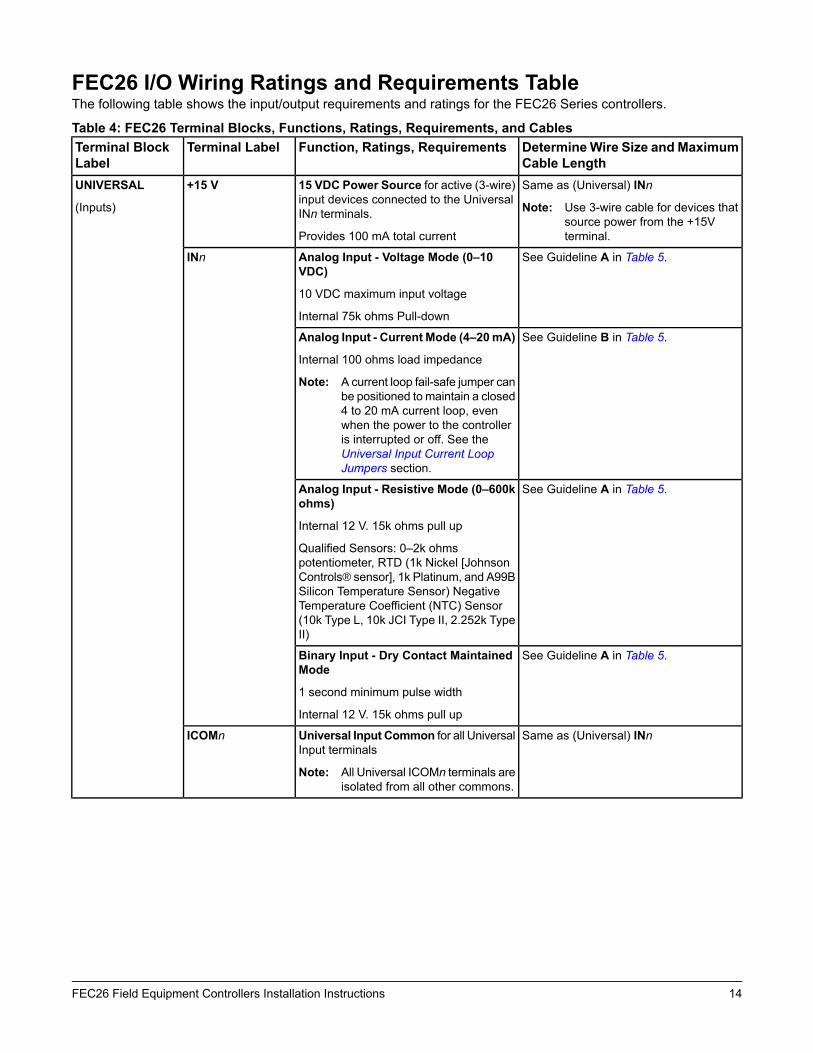
FEC26 I/O Wiring Ratings and Requirements TableThe following table shows the input/output requirements and ratings for the FEC26 Series controllers.
Table 4: FEC26 Terminal Blocks, Functions, Ratings, Requirements, and CablesDetermineWire Size and MaximumCable Length
Function, Ratings, RequirementsTerminal LabelTerminal BlockLabel
Same as (Universal) INn
Note: Use 3-wire cable for devices thatsource power from the +15Vterminal.
15 VDC Power Source for active (3-wire)input devices connected to the UniversalINn terminals.
Provides 100 mA total current
+15 VUNIVERSAL
(Inputs)
See Guideline A in Table 5.Analog Input - Voltage Mode (0–10VDC)
10 VDC maximum input voltage
Internal 75k ohms Pull-down
INn
See Guideline B in Table 5.Analog Input - Current Mode (4–20mA)
Internal 100 ohms load impedance
Note: A current loop fail-safe jumper canbe positioned to maintain a closed4 to 20 mA current loop, evenwhen the power to the controlleris interrupted or off. See theUniversal Input Current LoopJumpers section.
See Guideline A in Table 5.Analog Input - Resistive Mode (0–600kohms)
Internal 12 V. 15k ohms pull up
Qualified Sensors: 0–2k ohmspotentiometer, RTD (1k Nickel [JohnsonControls® sensor], 1k Platinum, and A99BSilicon Temperature Sensor) NegativeTemperature Coefficient (NTC) Sensor(10k Type L, 10k JCI Type II, 2.252k TypeII)
See Guideline A in Table 5.Binary Input - Dry Contact MaintainedMode
1 second minimum pulse width
Internal 12 V. 15k ohms pull up
Same as (Universal) INnUniversal Input Common for all UniversalInput terminals
Note: All Universal ICOMn terminals areisolated from all other commons.
ICOMn
14FEC26 Field Equipment Controllers Installation Instructions
Table 4: FEC26 Terminal Blocks, Functions, Ratings, Requirements, and CablesDetermineWire Size and MaximumCable Length
Function, Ratings, RequirementsTerminal LabelTerminal BlockLabel
See Guideline A in Table 5.Binary Input - Dry Contact MaintainedMode
0.01 second minimum pulse width
Internal 18 V. 3k ohms pull up
INnBINARY
(Inputs)
Binary Input - PulseCounter/Accumulator Mode
0.01 second minimum pulse width
(50 Hz at 50% duty cycle)
Internal 18 V. 3k ohms pull up
Binary Input Common for all Binary Input(IN) terminals
Note: All Binary ICOMn terminals areisolated from all other commons,except the Configurable Output(CO) common (OCOMn) when theCO is defined as an AnalogOutput.
ICOMn
See Guideline C in Table 5.Analog Output - Voltage Mode (0–10VDC)
10 VDC maximum output voltage
10 mA maximum output current
Required an external load of 1,000 ohmsor more.
Note: The Analog Output (AO) operatesin the Voltage Mode whenconnected to devices withimpedances greater than 1,000ohms. Devices that drop below1,000 ohms may not operate asintended for Voltage Modeapplications.
OUTnANALOG
(Outputs)
Analog Output - Current Mode (4–20mA)
Requires and external load between0–300 ohms.
Note: The AO operates in Current Modewhen connected to devices withimpedances less than 300 ohms.Devices that exceed 300 ohmsmay not operate as intended forCurrent Mode applications.
Analog Output Signal Common for allAnalog OUT terminals.
Note: All Analog Output Commonterminals (OCOMn) are isolatedfrom all other commons.
OCOMn
15FEC26 Field Equipment Controllers Installation Instructions
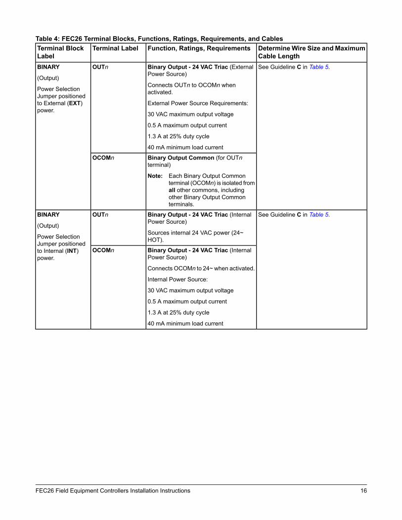
Table 4: FEC26 Terminal Blocks, Functions, Ratings, Requirements, and CablesDetermineWire Size and MaximumCable Length
Function, Ratings, RequirementsTerminal LabelTerminal BlockLabel
See Guideline C in Table 5.Binary Output - 24 VAC Triac (ExternalPower Source)
Connects OUTn to OCOMn whenactivated.
External Power Source Requirements:
30 VAC maximum output voltage
0.5 A maximum output current
1.3 A at 25% duty cycle
40 mA minimum load current
OUTnBINARY
(Output)
Power SelectionJumper positionedto External (EXT)power.
Binary Output Common (for OUTnterminal)
Note: Each Binary Output Commonterminal (OCOMn) is isolated fromall other commons, includingother Binary Output Commonterminals.
OCOMn
See Guideline C in Table 5.Binary Output - 24 VAC Triac (InternalPower Source)
Sources internal 24 VAC power (24~HOT).
OUTnBINARY
(Output)
Power SelectionJumper positionedto Internal (INT)power.
Binary Output - 24 VAC Triac (InternalPower Source)
Connects OCOMn to 24~ when activated.
Internal Power Source:
30 VAC maximum output voltage
0.5 A maximum output current
1.3 A at 25% duty cycle
40 mA minimum load current
OCOMn
16FEC26 Field Equipment Controllers Installation Instructions

Table 4: FEC26 Terminal Blocks, Functions, Ratings, Requirements, and CablesDetermineWire Size and MaximumCable Length
Function, Ratings, RequirementsTerminal LabelTerminal BlockLabel
See Guideline A in Table 5.Analog Output - Voltage Mode (0–10VDC)
10 VDC maximum output voltage
10 mA maximum output current
Required an external load of 1,000 ohmsor more.
OUTnCONFIGURABLE
(Outputs)
See Guideline C in Table 5.Binary Output - 24 VAC Triac (ExternalPower Source only)
Connects OUTn to OCOMn whenactivated.
External Power Source Requirements:
30 VAC maximum output voltage
0.5 A maximum output current
1.3 A at 25% duty cycle
40 mA minimum load current
Same as (Configurable) OUTn.Analog Output Signal Common AllConfigurable Outputs (COs) defined asAnalog Outputs (AOs) are isolated fromall other commons except the Binary Inputcommon.
OCOMn
Binary Output Signal Common AllConfigurable Outputs (COs) defined asBinary Outputs are isolated from all othercommons, including other CO commons.
17FEC26 Field Equipment Controllers Installation Instructions

Cable and Wire Length GuidelinesTable 5 defines cable length guidelines for the various wire sizes that may be used for wiring low-voltage (<30 V)input and outputs.Table 5: Cable Length Guidelines for Recommended Wire Sizes for Low-Voltage (<30 V) Inputs and Outputs
AssumptionsMaximum CableLength and Type
Wire Size/Gauge and TypeGuideline
100 mV maximum voltage drop
Depending on cable and the connected inputor output device, you may have to define anoffset in the setup software for the input oroutput point.
457 m (1,500 ft) twistedwire
1.0 mm (18 AWG) stranded copperA
297 m (975 ft) twisted wire0.8 mm (20 AWG) stranded copper
183 m (600 ft) twisted wire0.6 mm (22 AWG) stranded copper
107 m (350 ft) twisted wire0.5 mm (24 AWG) stranded copper
100 mV maximum voltage drop
Depending on cable and the connected inputor output device, you may have to define anoffset in the setup software for the input oroutput point.
229 m (750 ft) twisted wire1.0 mm (18 AWG) stranded copperB
137 m (450 ft) twisted wire0.8 mm (20 AWG) stranded copper
91 m (300 ft) twisted wire0.6 mm (22 AWG) stranded copper
61 m (200 ft) twisted wire0.5 mm (24 AWG) stranded copper
N/ASee Figure 8 to determinecable length. Use twistedwire cable.
See Figure 8 to select wire size/gauge.Use stranded copper wire
C
Maximum Cable Length versus Load CurrentUse Figure 8 to estimate the maximum cable length relative to the wire size and the load current (in mA) when wiringinputs and outputs.
Note: Figure 8 applies to low-voltage (<30 V) inputs and outputs only.
Figure 8: Maximum Wire Length for Low-Voltage (<30 V) Inputs and Outputs by Current and Wire Size
18FEC26 Field Equipment Controllers Installation Instructions

SA/FC Bus and Supply PowerWiring GuidelinesTable 6 provides information about the functions, ratings,and requirements for the communication bus and supplypower terminals; and guidelines for wire sizes, cabletypes, and cable lengths when wiring the controller'scommunication buses and supply power.
In addition to the guidelines in Table 6, observe theseguidelines when wiring an SA or FC bus and the 24 VACsupply power:
• Run all low-voltage wiring and cables separate fromhigh-voltage wiring.
• All SA and FC bus cables, regardless of wire size,should be twisted, insulated, stranded copper wire.
• Shielded cable is strongly recommended for all SAand FC bus cables.
• Refer to the MS/TP Communications Bus TechnicalBulletin (LIT-12011034) for detailed informationregarding wire size and cable length requirements forthe SA and FC buses.
Table 6: Communications Bus and Supply Power Terminal Blocks, Functions, Ratings, Requirements, andCables
Recommended Cable TypeFunction, Electrical Ratings/RequirementsTerminalLabels
TerminalBlock/PortLabel
0.6 mm (22 AWG) stranded, 3-wiretwisted, shielded cablerecommended
FC Bus Communications+
-FC BUS1
Signal Reference (Common) for Bus communicationsCOM
Isolated terminal (optional shield drain connection)SHLD
Wireless Commissioning Converterretractable cable or 24 AWG 3-pairCAT 3 Cable <30.5 m (100 ft)
RJ-12 6-Position Modular Connector provides:
FC Bus Communications
FC Bus Signal Reference and 15 VDC Common
15 VDC, 180 mA, Power for Wireless CommissioningConverter or ZFR181x/ZFR182x Wireless Router
FC BusFC BUS1
(Port)
0.6 mm (22 AWG) stranded, 4-wire(2 twisted-pairs), shielded cablerecommended.
Note: The + and - wire are onetwisted pair, and the COMand SA PWR are thesecond twisted pair ofwires.
SA Bus Communications+
-SA BUS1
SA Bus Signal Reference and 15 VDC CommonCOM
15 VDC Supply Power for Devices on the SA Bus
(Maximum total current draw for SA Bus is 240 mA.)
SA PWR
24 AWG 3-pair CAT3 cable <30.5m (100 ft)
RJ-12 6-Position Modular Connector provides:
SA Bus Communications
SA Bus Signal Reference and 15 VDC Common
15 VDC Power for devices on the SA bus and WirelessCommissioning Converter
SensorSensor1
0.8 mm to 1.0 mm
(18 AWG) 2-wire
24 VAC Power Supply - Hot
Supplies 20–30 VAC (Nominal 24 VAC)
HOT24~
24 VAC Power Supply Common (Isolated from all otherCommon terminals on controller)
35 VA
COM
1 The SA Bus and FC Bus wiring recommendations in this table are for MS/TP bus communications at 38.4k baud. For moreinformation, refer to the MS/TP Communications Bus Technical Bulletin (LIT-12011034).
19FEC26 Field Equipment Controllers Installation Instructions

Setup and Adjustments
Setting the Device AddressesMetasys® field controllers are master devices on MS/TP(SA or FC) buses. Before operating field controllers ona bus, you must set a valid and unique device addressfor each controller on the bus. You set a controller'sdevice address by setting the positions of the switcheson the DIP switch block at the top of the controller (Figure1). Device addresses 4 through 127 are the validaddresses for these controllers.
The DIP switch block has eight switches numbered 128,64, 32, 16, 8, 4, 2, and 1 (Figure 9). Switches 64 through1 are device address switches. Switch 128 is a modeswitch that enables a controller to operate on a ZFR/ZFRPro Series Wireless Field Bus. Switch 128 must be setto off for all hard-wired SA and FC bus applications. Setswitch 128 to ON for wireless FC bus applications only.
Figure 9: Device Address DIP Switch Block Set toAddress 21
Note: Metasys field controllers ship with switch 128 ONand the remaining address switches off renderingthe controllers wired slave devices, which do notoperate on MS/TP buses, but will not interferewith bus operation. Set a valid and unique deviceaddress on the controller before applying powerto the controller on the bus.
To set the device addresses onMetasys field controllers:
1. Set all of the switches on the address DIP switchblock (128 through 1) to OFF.
2. Set one or more of the seven address switches (64though 1) to ON, so that the sum of the switchnumbers set to ON equals the intended deviceaddress. See Table 7.
Set the highest number switch that is less than orequal to the intended device address to ON. Thencontinue setting lower-numbered switches until thetotal equals the intended address. For example, if theintended device address is 21, set switch 16 to ONfirst, then set switch 4 ON, followed by switch 1(16+4+1= 21). See Figure 9.
3. Set switch 128 to ON only for controllers on aZFR/ZFR Pro Series Wireless Field Bus application.For all hard-wired SA and FC bus applications, ensurethat switch 128 is set to OFF.
Note: Do not connect a controller with switch 128set to ON to an active (hard-wired) SA or FCbus. When a controller with switch 128 set toON and a device address from 4 to 127 isconnected to a wired field bus, the entire fieldbus is rendered inoperable until the controlleris disconnected or switch 128 is set to OFF.
Note: Refer to theWNC1800/ZFR182x Pro SeriesWireless Field Bus System Technical Bulletin(LIT-12012356) for more information on deviceaddresses in wireless applications.
4. Set a unique and sequential device address for eachof the controllers connected on the SA or FC busstarting with device address 4.
To ensure the best bus performance, set sequentialdevice addresses with no gaps in the device addressrange (4, 5, 6, 7, 8, 9, and so on). The controllers donot need to be physically connected on the bus intheir numerical device address order.
5. Write each field controller's device address on thewhite label below the DIP switch block on thecontroller's cover.
Table 7 describes the FC bus and SA bus devicesaddresses for Johnson Controls MS/TPcommunications bus applications.
Table 7: SA/FC Bus Device Address DescriptionsUse on DescriptionDevice
AddressReserved for FC Bus Supervisory Controller(not for use on field controllers).
0
(Switch128 Off)
Reserved for peripheral devices (not for useon field controllers).
1 to 3
(Switch128 Off)
Used for MS/TPmaster devices (field) that arehardwired to an SA Bus or FC Bus.
4 to 127
(Switch128 Off)
20FEC26 Field Equipment Controllers Installation Instructions

Table 7: SA/FC Bus Device Address DescriptionsUse on DescriptionDevice
AddressReserved addresses for wired slave devices(not for use on field controllers).
Note: Metasys field controllers ship withswitch 128 ON and the remainingaddress switches off rendering thecontrollers wired slave devices, whichdo not operate on MS/TP buses.
0 to 3
(Switch128 ON)
Valid for MS/TPMaster controllers onwirelessFC Buses only.
Note: Do not connect a field controller withswitch 128 ON to an active(hard-wired) SA or FC Bus. When acontroller with switch 128 ON and adevice address from 4 to 127 isconnected to a wired field bus, theentire field bus is rendered inoperableuntil the controller is disconnected orswitch 128 is set to off.
4 to 127
(Switch128 ON)
Setting the N2 Controller Address tobe Greater than 127N2-configured controllers support the full range ofpossible N2 device addresses provided by the N2 protocolstandard (1–255). However, these controllers requirespecial configuration for addresses above 127.
Use the following instructions for controllers greater than127.Note: Before you perform this procedure, make sure
that your controller has been converted fromBACnet to N2 protocol first. Refer to theModernization Guide for Legacy N2 Controllers(LIT-12012005) for more information.
Note: This special configuration is required becausecontroller addresses above 127 were originallyintended for use with the Wireless Field Bussystem.
1. Disconnect the 24 VAC supply from the controller.2. Remove the FC Bus connector from the controller.3. Set the address switch set to the desired N2 address.4. Set the address switch segment labeled 128 to OFF.5. Reconnect the 24 VAC supply to the controller.6. Using an SA bus connection, download the firmware
and controller application file. The download processasks to confirm switching the communication protocolto N2.
7. Click OK.8. After the download is finished, disconnect the 24
VAC supply to the controller.9. Set the address switch segment labeled 128 to ON.10. Reattach the FC Bus connector to the controller.11. Reconnect the 24 VAC supply to the controller.
21FEC26 Field Equipment Controllers Installation Instructions

Removing the Controller CoverImportant: Electrostatic discharge can damage
controller components. Use properelectrostatic discharge precautions duringinstallation, setup, and servicing to avoiddamaging the controller.
Important: Disconnect all power sources to thecontroller before removing cover andchanging the position of any jumper or theEOL switch on the controller. Failure todisconnect power before changing a jumperor EOL switch position can result in damageto the controller and void any warranties.
The controller cover is held in place by four plastic latchesthat extend from the base and snap into slots on theinside of the housing cover.
To remove the controller cover:
1. Place your fingernails under the two cover lift tabs onthe sides of the housing cover and gently pry the topof the cover away from the base to release the coverfrom the two upper latches.
2. Pivot the top of the cover further to release it from thelower two latches.
3. Replace the cover by placing it squarely over thebase, and then gently and evenly push the cover onto the latches until they snap into the latched position.
Figure 10: FEC26 with Cover Removed Showing EOLSwitch and Jumper Positions
Setting the End-of-Line (EOL) SwitchEach controller has an EOL switch, which, when set toON, sets the controller as a terminating device on thebus. See Figure 10 for the EOL switch location. Thedefault EOL switch position is OFF.
Figure 11: End-of-Line Switch Positions
To set the EOL switch on a field controller:
1. Determine the physical location of the controller onthe FC bus.
2. Determine if the controller must be set as aterminating device on the bus.
Note: Refer to the MS/TP Communications BusTechnical Bulletin (LIT-12011034)for detailedinformation regarding EOL termination rulesand EOL switch settings on FC buses.
3. If the controller is a terminating device on the FC bus,set the EOL switch to ON. If the controller is not aterminating device on the bus, set the EOL switch toOFF.
When a field controller is connected to power with itsEOL switch set to ON, the amber EOL LED on thecontroller cover is lit.
Setting the Input and OutputJumpers
Binary Output (BO) Source PowerSelection Jumpers
Risk of Electric Shock: Disconnect supply power tothe field controller before attempting to adjust the BinaryOutput Source Power Selection Jumpers. Failure todisconnect the supply power may result in electric shock.
Mise En Garde: Risque de décharge électrique:Débrancher l'alimentation de l'controller avant toutréglage du Binary Output Source Power SelectionJumpers. Le non-respect de cette précaution risque deprovoquer une décharge électrique.
22FEC26 Field Equipment Controllers Installation Instructions

Important: Do not connect an external power sourceto a BO when the BO power source jumperis in the internal power (INT) position.Connecting external power to a BO thatsources internal power can damage thecontroller and void any warranties.
The BO source power selection jumpers determinewhether a BO provides internal power (sourced from thecontroller) to the output load (INT position) or requiresan external power source (EXT position) for the outputload. Figure 12 shows an example of a controller BOsand the associated power selection jumpers to the rightof the BOs terminal block.
Figure 12: Example Binary Outputs and theAssociated Source Power Jumper Positions
Universal Input Current Loop JumpersThe Universal Input (UI) current loop fail-safe jumpersare on the circuit board under the controller cover nearthe UI terminals (Figure 10). When a UI is defined (in thesystem software) as a 4-20 mA Analog Input and the UI’scurrent loop jumper is in the Disabled (default) position(Figure 13), the 4-20 mA current loop circuit openswhenever power to the controller is interrupted or off.
Figure 13: Current Loop Jumper Positions
Setting the current loop jumper to the Enabled position(Figure 13) connects an internal 100 ohm resistor acrossthe UI terminals, which maintains the 4-20 mA currentloop circuit even when power to the controller isinterrupted or off.
Important: Current Loop jumpers must be in theDisabled (default) position for all UIs thatare not set up to operate as 4-20 mA analoginputs.
Table 8 identifies the current loop jumpers associatedwith each UI on the FEC26 controller.
Table 8: FEC26 UI Inputs and Jumper LabelsJumper Label on Circuit BoardUniversal Input
LabelJ20IN1
J21IN2
J22IN3
J23IN4
J24IN5
J25IN6
Setting Up an Integral or LocalDisplayFEC2621 models have an integral LCD and push buttonuser interface that allows you to set up and monitor theFEC, the FEC I/O points, and the modules and I/O pointsconnected on the SA bus. FEC2611 models do not havean integral display, but can be connected to a DIS1710Local Controller Display. For detailed information onsetting up and operating either an integral user interfaceor a remotely connected DIS1710 display, refer to theDIS1710 Local Controller Display Technical Bulletin(LIT-12011270).
Commissioning Field ControllersYou commission field controllers with the ControllerConfiguration Tool (CCT) software, via a Bluetooth®Wireless Commissioning Converter, a USB dongle withZigBee®, Ethernet connection, or in BACnet router modewhen connected to an NAE or NCE. Refer to theController Tool Help (LIT-12011147) for detailedinformation on commissioning controllers.
23FEC26 Field Equipment Controllers Installation Instructions

Troubleshooting FieldControllers Observe the Status LEDs on the front of the fieldcontroller and see Table 9 to troubleshoot the controller.To troubleshoot a local controller display, refer to theDIS1710 Local Controller Display Technical Bulletin(LIT-12011270).
Table 9: Status LEDs and Descriptions of LED StatesDescription of LED StatesNormal LED
StateLED ColorLED Label
Off Steady = No Supply Power or the controller’s polyswitch/resettable fuseis open. Check Output wiring for short circuits and cycle power to controller.
On Steady = Power Connected
On SteadyGreenPOWER
Off Steady = No Faults
On Steady = Device Fault; no application loaded; Main Code downloadrequired, if controller is in Boot mode, or a firmware mismatch exists betweenthe FEC and the ZFR1811 Wireless Field Bus Router.
Blink - 2 Hz = Download or Startup in progress, not ready for normal operation
Off SteadyRedFAULT
Blink - 2 Hz = Data Transmission (normal communication)
Off Steady = No Data Transmission (N/A - auto baud not supported)
On Steady = Communication lost, waiting to join communication ring
Blink - 2 HzGreenSA BUS
Blink - 2 Hz = Data Transmission (normal communication)
Off Steady = No Data Transmission (auto baud in progress)
On Steady = Communication lost, waiting to join communication ring
Blink - 2 HzGreenFC BUS
On Steady = EOL switch in ON position
Off Steady = EOL switch in Off position
Off (Except onterminatingdevices)
AmberEOL
Repair InformationIf a controller fails to operate within its specifications,replace the controller. For a replacement controller,contact your Johnson Controls representative.
For the MS-FEC2611-0U and MS-FEC2621-0U modelsthat are UL 864 10th Edition UUKL/ORD-C100-13UUKLClisted for smoke control, contact the Johnson ControlsRepair Center in Louisville, Kentucky, at 1-502-671-7312.
AccessoriesSee Table 10 for controller accessories ordering information.Table 10: Accessories Ordering Information
DescriptionProduct Code NumberLocal Controller Display (for use with MS-FEC2611 model only)MS-DIS1710-0
Transformer, 120 VAC Primary to 24 VAC secondary, 20 VA, Wall PlugTP-2420
Transformer, 120/208/240 VAC Primary to 24 VAC Secondary, 40 VA, Foot Mount, 8 in.Primary Leads and Secondary Screw Terminals, Class 2
Note: Additional Y6x-x Series transformers are also available. Refer to the Series Y63,Y64, Y65, Y66, and Y69 Transformers Product Bulletin (LIT-125755) for moreinformation.
Y65T31-0
Power transformer (Class 2, 24 VAC, 50 VA maximum output), no enclosureAS-XFR050-0
Replacement SA Bus Terminal Blocks, 4-Position, Brown, Bulk Pack of 10AP-TBK4SA-0
Replacement FC Bus Terminal Blocks, 4-Position, Blue, Bulk Pack of 10AP-TBK4FC-0
24FEC26 Field Equipment Controllers Installation Instructions

Table 10: Accessories Ordering InformationDescriptionProduct Code NumberReplacement Power Terminal Blocks, 3-Position, Gray, Bulk Pack of 10AP-TBK3PW-0
This system is used for installations that support BACnet/IP but can also coexist with theZFR1800 Series when installed under the same supervisor (i.e., network engine). Referto theWNC1800/ZFR182x Pro Series Wireless Field Bus System Product Bulletin(LIT-12012320) for a list of available products.
WNC1800/ZFR182x Pro Wirelessfield Bus System
This system is used for installations that only support BACnet MS/TP. Refer to the ZFR1800Series Wireless Field Bus System Product Bulletin (LIT-12011336) for a list of availableproducts.
ZFR1800 Series Wireless FieldBus System
Refer to theNS Series Network Sensors Product Bulletin (LIT-12011574) for specific sensormodel descriptions.
NS Series Network Sensors
Refer to theWRZ Series Wireless Room Sensors Product Bulletin (LIT-12000653) forspecific sensor model descriptions.
WRZ Series Wireless RoomSensors
Technical SpecificationsTable 11: FEC26 Technical Specifications
MS-FEC2611-0: 17-Point FEC
MS-FEC2611-0ET: FEC2611 Extended Temperature controller for rooftopapplications. Supports Operational Temperature Range of -40 °C to 70 °C (-40 °Fto 158°F).
MS-FEC2621-0: 17-Point FEC with integral display and pushbutton user interface.
Smoke Control Models:
MS-FEC2611-0U
MS-FEC2621-0U
Product Code Numbers
24 VAC (nominal, 20 VAC minimum/30 VAC maximum), 50/60 Hz, power supplyClass 2 (North America), Safety Extra-Low Voltage (SELV) (Europe)
Supply Voltage
14 VA maximum for FEC2611 only
20 VA maximum for FEC2621 (with integral display) only
Note: VA rating does not include any power supplied to the peripheral devicesconnected to Binary Outputs (BOs) or Configurable Outputs (COs), whichcan consume up to 12 VA for each BO or CO; for a possible totalconsumption of an additional 84 VA (maximum).
Power Consumption
FEC26 Field Equipment Controller:
Operating: 0 to 50°C (32 to 122°F); 10 to 90% RH noncondensing
Storage: -40 to 80°C (-40 to 176°F); 5 to 95% RH noncondensing
FEC26 Extended Temperature Field Equipment Controller:
Operating: - 40 to 70°C (-40 to 158°F); 10 to 90% RH noncondensing
Storage: -40 to 80°C (-40 to 176°F); 5 to 95% RH noncondensing
Ambient Conditions
BACnet® MS/TP: DIP switch set; valid field controller device addresses 4–127(Device addresses 0–3 and 128–255 are reserved and not valid controller addresses.)
N2: DIP switch set; valid controller device addresses 1–255
Addressing
25FEC26 Field Equipment Controllers Installation Instructions

Table 11: FEC26 Technical SpecificationsRS-485, field selectable between BACnet MS/TP and N2 communications:
3-wire FC Bus between supervisory controller and field controllers.
4-wire SA Bus between field controller, network sensors, and other sensor/actuatordevices, includes a lead to source 15 VDC supply power (from field controller) tobus devices.
N2 Open Protocol:
N2/FC Bus: 1.0mm (18 AWG) standard 3-wire, twisted, shielded cable recommendedbetween the supervisory controller and field controllers
Communications Bus
FEC26 Series: H8SX/166xR Renesas® 32-bit microcontrollerProcessor
640 KB flash memory and 128 KB RAMMemory
FEC26 Series:
6 - Universal Inputs: Defined as 0–10 VDC, 4-20 mA, 0–600k ohm, or Binary DryContact
2 - Binary Inputs:Defined as Dry Contact Maintained or Pulse Counter/AccumulatorMode
3 - Binary Outputs: Defined as 24 VAC Triac (selectable internal or external sourcepower)
4 - Configurable Outputs: Defined as 0–10 VDC or 24 VAC/DC Field-EffectTransistor (FET) BO
2 - Analog Outputs: Defined as 0–10 VDC or 4–20 mA
Input and Output Capabilities
Input: 16-bit resolution
Output: 16-bit resolution, +/- 200 mV accuracy in 0-10 VDC applications
Analog Input/AnalogOutput Resolutionand Accuracy
Input/Output: Fixed Screw Terminal Blocks
SA/FC Bus and Supply Power: 4-Wire and 3-Wire Pluggable Screw TerminalBlocks
SA/FC Bus Port: RJ-12 6-Pin Modular Jacks
Terminations
Horizontal on single 35 mmDIN rail mount (preferred), or screwmount on flat surfacewith three integral mounting clips on controller
Mounting
Enclosure material: ABS and polycarbonate, Rating V0 minimum
Protection Class: IP20 (IEC529)
Housing
FEC26 Series: 150 x 190 x 53 mm (5-7/8 x 7-1/2 x 2-1/8 in.) including terminals andmounting clips
Note: Mounting space requires an additional 50 mm (2 in.) space on top, bottomand front face of controller for easy cover removal, ventilation and wireterminations.
Dimensions(Height x Width x Depth)
0.5 kg (1.1 lb)Weight
26FEC26 Field Equipment Controllers Installation Instructions

Table 11: FEC26 Technical SpecificationsUnited States: UL Listed, File E107041, CCN PAZX, UL 916, Energy ManagementEquipment; UL Listed, File S4977, UUKL 864 - 10th Edition, Smoke ControlEquipment (MS-FEC2611-0U and MS-FEC2621-0U models only)
FCC Compliant to CFR47, Part 15, Subpart B, Class A
Compliance
Canada: UL Listed, File E107041, CCN PAZX7 CAN/CSA C22.2 No.205, SignalEquipment
Industry Canada Compliant, ICES-003
Europe: Johnson Controls declares that this product is in compliance with theessential requirements and other relevant provisions of the EMC Directive.
Australia and New Zealand: RCM Mark, Australia/NZ Emissions Compliant
BACnet International: BACnet Testing Laboratories (BTL) Protocol Revision 9Listed BACnet Application Specific Controller (B-ASC)
The performance specifications are nominal and conform to acceptable industry standard. For application at conditionsbeyond these specifications, consult the local Johnson Controls® office. Johnson Controls shall not be liable fordamages resulting from misapplication or misuse of its products.
APAC Single Point of Contact:NA/SA Single Point of Contact:European Single Point of Contact:JOHNSON CONTROLS
C/O CONTROLS PRODUCTMANAGEMENT
NO. 22 BLOCK D NEW DISTRICT
WUXI JIANGSU PROVINCE 214142
CHINA
JOHNSON CONTROLS
507 E MICHIGAN ST
MILWAUKEE WI 53202
USA
JOHNSON CONTROLS
WESTENDHOF 3
45143 ESSEN
GERMANY
Building Technologies & Solutions507 E. Michigan Street, Milwaukee, WI 53202
Johnson Controls® is a registered trademark of Johnson Controls.All other marks herein are the marks of their respective owners.© 2017 Johnson Controls
www.johnsoncontrols.comPublished in U.S.A.
27FEC26 Field Equipment Controllers Installation Instructions