fedex flight 647
TRANSCRIPT


CC: Chairman Ellen Engleman Conners Member Mark V. Rosenker Member Carol J. Carmody Member Richard F. Healing Member Deborah A. P. Hersman Tom Haueter, NTSB John Clark, NTSB T.R. Proven, FAA Alan W. Ray, FedEx Express William C. Steelhammer, The Boeing Company Thomas E. Wallace, Memphis-Shelby County Airport Authority
3
ATTACHMENT 1 - FINDINGS FINDINGS
1. The MD-10 program has effectively improved the capability and service life of the DC-10 airframes, however, the program does not change the flying characteristics of the MD-11 or MD-10 enough to enable them to be called the same aircraft.
2. While the MD-10 and MD-11 are certified as the same type, no changes were made to the
wings, flight controls or engines of the MD-10 from the DC-10. Therefore, DC-10 wind corrections should be used for the MD-10. Using the wind additive appropriate for the MD-11 reduces airspeed safety margins on MD-10 aircraft especially at low altitude while on approach.
3. The handling characteristics of the MD-11 are distinctly different than the handling
characteristics of the DC/MD-10. This is due to a longer wing with winglets, a longer fuselage and a horizontal stabilizer that is 60 percent the size of the DC-10. Additionally the MD-11 has an auto pitch trim system, Longitudinal Stability Augmentation System (LSAS) with the feature that auto trims when hand flying.
4. In order to receive a common type rating, the FAA required that the MD-11 and MD-10
have flying and handling characteristics that were similar. The easiest way to accomplish this was to change the MD-11 Flight Control Computer (FCC) software to make the MD-11 fly similar to the MD-10. New FCC software, the FCC-908 load, was introduced and is required in order to fly both the MD-11 and MD-10. While most of the FCC-908 load changes have improved the handling characteristics of the MD-11, the changes have not made the MD-11 fly like the DC/MD-10.
5. Until November 2004, FedEx IOE (Initial Operating Experience) students were not
required to fly more than one of the MD-10/11 type variants (MD-11, or either the MD-10-10 or the -30). The entire IOE may well have been conducted in just one version.
6. At the time the First Officer was trained, the first time a FedEx pilot performed an MD-
10 landing was in the actual aircraft, and could have been many months after completing differences training.
7. The FedEx MD10-30 simulator is not being used for Proficiency Checks (PCs) due to
considerations of the FAA-certified MD-11 and MD-10 training syllabus.
8. Many MD-11 pilots, especially those acting frequently as Relief First Officers (RFO's), have not been able to maintain currency in the aircraft and must get their required three takeoffs and three landings in the simulator.

4
9. Certifying the MD-10 with a same type rating as the MD-11 and not requiring currency in both aircraft has resulted in pilots going months and in some cases years between flying each aircraft. The First Officer in this accident was conducting only her third landing in the MD-10 in the preceding 12 months, including the one the day before.
10. Due to the FedEx fleet being composed largely of aircraft that started out with other
carriers, the escape slide configurations and procedures for manual deployment vary from aircraft to aircraft. This can lead to confusion or improper deployment of the escape slide system.
11. The slides on the accident aircraft were certified to a lower standard than required by
current slide requirements. These slides did not meet the current wind requirements. One slide was unusable due to fire, and the other blew under the aircraft fuselage when deployed, rendering it useless, and forcing the crew to find another means of egress from a burning aircraft.
12. Since the slide was unusable, the crew had to rely on egressing out the Captain’s and
First Officer’s clearview windows using escape tape.
13. Because of the construction of escape tape, a thin ribbon of reinforced synthetic material, one of the crew suffered burns to the hands. If a crewmember had been incapacitated, there would have been no means to evacuate him or her safely from the burning wreckage.
14. One crewmember was injured by falling while trying to use the escape tape.
15. Prior to January 2004 there was no girt bar attached to the girt bar locking brackets at the
doorsill on the FedEx MD-10 door training equipment at the Memphis, Tennessee training facility. Without the girt bar, crews are unable to train for manual slide inflation on a door that accurately models the actual aircraft.
16. During the investigation, it was found that FedEx MD-11 and MD-10 crews were not
getting “hands-on” experience with escape slide manual inflation. A flight-training manager at FedEx stated that when the girt bar flap had been installed on the MD-10 door training equipment, the use of the manual inflation handle was not part of the Emergency Procedures Training (EPT) hands-on drill.
17. A FedEx check airman stated that he recalled that procedures for operating the manual
lanyards attached to the slide were taught during classroom instruction. He said that demonstration and practical application of those procedures were not practiced.
18. ATC informed the Chief of Airport Fire Station #33 that there were only 3 souls on board
the airplane, based solely on an erroneous assumption, not on information obtained from the flight crew or dispatch. This resulted in a smaller ARFF response in the early stages of the accident.
5
19. The Rural Metro Fire Department (RMFD), located on the FedEx ramp, had difficulties
responding to the accident due to an incoming airplane on runway 27/9. ATC allowed that aircraft to land which delayed the RMFD fire truck for about 1 – 1½ minutes.
20. The aircraft encountered strong, variable and gusting winds during the last 60 seconds of
flight.
21. According to FDR data there was a 47 degree wind shift, from 291 degrees to 338 degrees, just six seconds prior to touchdown.
22. The FDR also recorded wind gusts with speeds ranging from 24 to 33 knots one minute
before touchdown.
23. Between ten and six seconds before touchdown, the FDR recorded wind speed drops from 33 knots down to 17 knots, a 16 knot decrease.
24. Two seconds before touchdown, the FDR recorded a wind increase to 21 knots, and then
falls to 15 knots just after touchdown.
25. The wind sensor, one mile away from the accident site, recorded gusty and variable winds at its location during the last 10 seconds of flight.
26. At the sensor location there was a 55 degree wind shift followed by another 45 degree
shift at the sensor location, during the last 10 seconds of flight.
27. At the same sensor location, wind speed drops 16 knots during the final 10 seconds of flight.
28. The aileron position data recorded on the FDR does not comply with FAA requirements.
6
ATTACHMENT 2 – SAFETY RECOMMENDATIONS SAFETY RECOMMENDATIONS ALPA offers the following Safety Recommendations to attempt to correct deficiencies identified during the course of this accident investigation. To the Federal Aviation Administration (FAA) 1. Require an immediate review of wind additives for the MD-11 and MD-10 be conducted to
insure the MD-10 is being operated safely. 2. When a second MD-10 simulator is added, it should be in an MD-10-10 configuration. 3. Require that operators of the MD-10 train so that IOE legs are flown in the MD-11 and both
MD-10 variants. 4. Require that operators, who fly MD-11 and MD-10 aircraft, give pilots annual recurrent
training on the differences in MD-10 piloting technique if they have not flown the aircraft during the previous year.
5. Require modification to the MD-10 and MD-11 windshear alert and guidance system
(WAGS) to make it active until touchdown. 6. Require that all aircraft equipped with escape slides be retrofitted with slides that meet the
current FAR 25.810 requirements. 7. Require operators and aircraft manufacturers to install an inertia reel at slide equipped doors
to function as a backup in the event of escape slide malfunction. This will allow evacuation without the risk of “rope burns” or falling to the ground. This will also aid in evacuation of passengers or crew who may have become incapacitated.
8. Require that operators install the “Emergency Evacuation Checklist” on the pilots chart
holder on both yokes. It should be printed in luminescent print to allow for visibility in low-light conditions.
9. Emergency evacuation training should be conducted by all operators on all Proficiency
Training and Proficiency Checks. 10. Require operators to add training on manual inflation of the escape slide as part of the
Emergency Procedures Training (EPT) hands-on drill.
7
11. Require all escape slide simulators to be configured and painted to more closely resemble the installation in the actual aircraft.
12. Communicate with all ARFF and air traffic control tower personnel at airports that wide
body cargo aircraft operate from and convey that they sometimes transport as many as 27 persons on their wide body airplanes, many of which will be in the aft section of the plane.
13. Develop an addition to the flight training syllabus at cargo carriers that carry occupants in the
rear of the aircraft, to create awareness on the part of the crewmembers on how to deal with an emergency evacuation involving passengers occupying the seat pallets in the rear of the aircraft.
14. Verify that all airports and ARFF stations have received a copy of FAA CertAlert No. 04-01,
“Passengers and Crew on Cargo Aircraft”. 15. The NTSB and FAA should reexamine Safety Recommendation A-03-016, which
recommends that the FAA survey all other aircraft required to have flight data recorders to ensure they meet the requirements of 14 CFR Part 121.344 Appendix M, and determine if the alternate action is truly acceptable.
16. The FAA should mandate that the aircraft manufacturer should either use a different source
for the aileron position data with a refresh rate at least as high as the sampling requirement, or change the current system so that it updates at a high enough rate to meet the requirement.

SUBMISSION OF THE
AIR LINE PILOTS ASSOCIATION
TO THE
NATIONAL TRANSPORTATION SAFETY BOARD
REGARDING THE ACCIDENT INVOLVING
FedEx Flight 647
At MEMPHIS, TENNESSEE
ON DECEMBER 18, 2003

i
TABLE OF CONTENTS FedEx Flight 647 SUBMISSION
1. HISTORY OF FLIGHT................................................…………………………1 2. OPERATIONS..................................................................………………..…….……2
A. Operations and Training…...........................................………………………..2 B. Approach Speed Addition Differences on the MD-11, MD-10 and DC-10….5
C. Full Authority Digital Engine Control (FADEC)..............................................5 D. Currency........................................................................................................6 E. Handling Characteristics................................................................................6 F. Windshear Alert and Guidance System.........................................................7 G. Simulator Back Drive Activity........................................................................ 7
3. METEOROLOGY………………........................................................................9 A. General Synopsis..........................................................................................9
4. SURVIVAL FACTORS......................................................................………… 10 A. Escape Slide Issues………..……..……....................................................…. 10 B. FedEx Slide Training and Training Aids………….…………………………….11 C. ARFF Response………..……………………………………..…………………. 12 D. Evacuation Checklist………..………………………………..……………….….13
5. AIRWORTHINESS….………….......................................................................15
6. LIGHT DATA RECORDER (FDR)......................……………………….……..15 A. Wind Recorded on the FDR………………………....................................….. 15 B. Aileron Sampling ....................................................................................….. 17
7 COCKPIT VOICE RECORDER (CVR)......................…….…………………. 20 8 AIRCRAFT PERFORMANCE........................................................................ 20 9. MATERIALS LABORATORY REPORT.......................................................21
10. FINDINGS.........................………………………………..……………………… 21
11. SAFETY RECOMMENDATIONS.................………...………..…………….. 23

ii
LIST OF FIGURES
Wind Direction – Figure 1………………………..........………………………….…...16 Wind Speed – Figure 2...................................................................................................17
LIST OF APPENDICES
Correspondence on Common Type Rating............…………...…...APPENDIX A FAA CertAlert No. 04-01, “Passengers and Crew on Cargo Aircraft”........APPENDIX B

1
1. HISTORY OF FLIGHT On December 18, 2003, at approximately 1226 CST, a McDonnell Douglas MD-10-10F, N364FE, operated by FedEx as Flight No. 647, crashed during landing at Memphis International Airport (MEM), Memphis, Tennessee. The right main landing gear collapsed during the landing rollout on Runway 36 Right approximately 15 seconds after touchdown. The airplane ultimately veered off the right side of the runway and was destroyed during a subsequent fire. Flight No. 647 was being operated under the provisions of 14 Code of Federal Regulations (CFR) Part 121 on an instrument flight rules flight plan. Of the two flightcrew members and five passengers onboard the airplane, two suffered minor injuries during the evacuation. ALPA believes that this accident, like all others, was the combination of many factors. This event appears to have been caused by strong, gusting winds in the final 60 seconds of flight which, along with the crew’s unsuccessful attempt to arrest a high sink rate in the last ten seconds of flight. The available evidence also suggests that the flying pilot’s input during the landing flare was ineffective due to her lack of experience (in both training and operations) in this variant of the aircraft The accident occurred on the fourth day of the flight crew’s three leg trip pairing. The captain of the flight was a company check airman who was conducting a multi-leg line check for the first officer. In addition to the flight crew, a FedEx DC-10 captain occupied the cockpit right observer jumpseat and four FedEx pilots occupied the courier seats located in the cabin directly aft of the cockpit. The first leg was conducted in an MD-11 and departed Memphis on the evening of December 15th, 2003, with the captain acting as the pilot flying (PF). The second leg was flown in an MD-10 and departed Indianapolis on the afternoon of December 16th, 2003, bound for Oakland International Airport, Oakland, California (OAK). The flight crew remained in OAK on December 17, 2003. The accident flight was flown in an MD-10 and departed OAK on December 18, 2003, at 0632 PST for MEM. The first officer was the PF on this leg, and the flight was scheduled to arrive in MEM at 1350 CST on December 18th. According to the flight crew, the takeoff, taxi, climb, enroute and descent segments of the flight from OAK to MEM were normal. The descent and initial approach to MEM were conducted using the autopilot and autothrottles. The crew also stated that below 10,000 feet mean sea level (MSL), they experienced light to moderate turbulence that “would come and go.” The captain stated that he received the Memphis weather via the automated terminal information service (ATIS) several times before landing at MEM. The first ATIS broadcast indicated the wind from 290 degrees at 18 knots, with gusts to 23 knots. After a discussion with the first officer, the captain programmed the flight management system (FMS) for a landing on runway 27. In the descent, the captain received an updated ATIS that indicated the wind from 320 degrees at 18 knots, with gusts to 23 knots and noted that windshear advisories were in effect.

2
The captain then reprogrammed the FMS for a landing on runway 36L. Memphis approach control initially advised the crew to expect runway 36L, but later switched them to runway 36R for landing. When the flight was approximately 10 miles from touchdown, approach control cleared the crew for a visual approach to runway 36R, and they were instructed to contact the air traffic control tower. The crew contacted the MEM tower when the flight was approximately seven miles from touchdown. At that time, the tower cleared the crew to land on runway 36R and advised that there was a “gain and loss of ten knots on short final.” The first officer reported that there was a brief aural “windshear” alert, generated by the airplane’s central aural warning system (CAWS), at 1460 feet AGL. The captain stated that the alert lasted only about two seconds. Following that alert, the crew decided that conditions were still acceptable to continue the approach. According to the flight crewmembers, the visual approach to runway 36R was normal and the airplane was stabilized throughout the approach from above 1,000 feet above ground level (AGL). The crew had also made the correct wind correction/addition based on the reported winds. The crewmembers stated that the initial rollout appeared normal, but after several seconds, the airplane began to bank and turn to the right. They said that they were unable to steer the airplane back to the left and it skidded off the right side of the runway and came to a stop in the grass. Shortly after coming to a stop, the captain stated that there was a “huge explosion”, and a fire developed on the right side to the airplane. All seven individuals on the airplane were able to successfully evacuate the airplane using the cockpit windows.
2. OPERATIONAL FACTORS The intent of the program to convert the DC-10 to the MD-10 was to extend the capability and service life of the DC-10 airframes. The conversion process entails numerous changes to the way systems operate and the cockpit layout and displays, all with the goal of turning a three-pilot aircraft (the DC-10) into a two-pilot aircraft (the MD-10). The flight characteristics of the MD-10 remain the same as the DC-10. In an attempt to achieve a common type rating, the flight control computer software of the MD-11 was altered with the intent of making the MD-11 and MD-10 have similar handling qualities. In ALPA’s view, the changes to both aircraft do not successfully change the MD-11 or MD-10 enough to enable them to be flown as though they were the same aircraft. In fact, the three variants (MD-11, MD-10-10 and MD-10-30) all have unique characteristics, including: engines, fuselage and wing span differences, as well as weight differences. A. Operations and Training The modifications to the DC-10 system controls have resulted in the elimination of the requirement for a flight engineer by automating a number of aircraft system control functions. While these changes help a two pilot crew monitor systems, because of the inherent differences of the MD-10 and MD-11, not only is the workload higher for the crew, but the two aircraft

3
actually fly very differently. The FAA has determined that the MD-10 and MD-11 may be operated under a common type rating. In other words a pilot with an MD-11 type rating can fly both the MD-11 the MD-10 after completing difference training for the MD-10. Currency on each aircraft individually is not required by the FAA or the operator. In practice, this means FedEx pilots may fly only one of the two for an extended period, and then fly the other with no requirement for any refresher training. It may also mean that a pilot may fly both aircraft (MD-11 and MD-10) on the same trip, in some cases on back-to-back legs. The FedEx Pilots Association (FPA), which represented the pilots flying for FedEx Express until mid-2002, and has since merged with the Air Line Pilots Association, International, had several major concerns with the common type rating for the MD-11 and MD-10. The FPA made these objections known to the FAA1. The FAA responded that these FPA concerns would be taken into account by the FOEB, but in the end, they were not adequately addressed (APPENDIX A). 2,3 While there are many commonalities between the MD-10 & MD-11, there are differences that are of a safety concern. These differences were not individually considered to be safety critical items by the FAA. However, ALPA feels that all the differences in combination could lead to confusion on the flight deck as well as increased pilot workload and the consequent distraction from basic flying tasks, especially during a critical phase of flight. These differences include:
• Full Authority Digital Engine Control (FADEC) - the MD-10 is not modified with FADEC, but the MD-11 is.
• Autobrakes - only some MD-10s have autobrakes; all MD-11s have autobrakes. • Handling Characteristics - the MD-11 has distinctly different handling characteristics
than the DC/MD-10 because of a longer wing with winglets, a longer fuselage, and a horizontal stabilizer that is 60 percent the size of the DC-10. Additionally the MD-11 has an auto pitch trim system, Longitudinal Stability Augmentation System (LSAS), with the feature that auto trims when hand flying. The MD-10 versions require manual trim inputs.
The FAA also required that the MD-11 and MD-10 have flying and handling characteristics that were similar. The easiest way to accomplish this was to change the MD-11 Flight Control Computer (FCC) software load and make the MD-11 fly more like the MD-10. Early in the program, the MD-11 FCC software was known as the FCC-907 load and did not achieve the goal of making the MD-11 fly like a DC-10. A new FCC-908 load was introduced and is required in
1 3 Feb. 2001 letter from Michael Weiland, Pres. FPA to Jane F. Garvey FAA Administrator 2 23 Feb. 2001 letter from Jane F. Garvey FAA Administrator to Michael Weiland, Pres. FPA 3 4 Jan. 2001 letter from Thomas E. McSweeny FAA Associate Admin. For Regulation and
Certification To Michael Weiland, Pres. FPA

4
order to fly both the MD-11 and MD-10. A number of the changes in the FCC-908 load reflect the attempt to correct for differences in pitch and speed control of the two aircraft. These changes include:
• Pitch Rate Damper (PRD) 30 percent active below 16,500 feet, instead of phasing out by 15,000 feet .
• Pitch Attitude Protection down to 0 feet.
• Positive Nose Lowering (PNL) of 3 degrees nose down elevator on landing with main
wheel spin-up and additional 1-degree nose down elevator with spoilers greater then 10 degrees.
• Auto Throttle and AP/FD Speed Protection.
The Pitch Rate Damper and leverage of the elevators, due to the longer fuselage on the MD-11, have not substantially countered the reduced size of the elevator and horizontal stabilizer. During the flare and landing phase most pilots use some power to counter the sink rate instead of applying elevator as used in many aircraft. While most of the FCC-908 load changes have improved the handling characteristics of the MD-11, the changes have not made the MD-11 fly like the DC/MD-10. ALPA feels the training available to the accident crew was inadequate. Originally, in FedEx Transition/Upgrade training, the student was not required to fly all three variants (MD-11, MD-10-30, and MD-10-10) during Initial Operating Experience (IOE). He or she may well have flown all of the IOE in only one of the variants, and not operate the others for an extended period of time. Although this has been changed since the accident, many pilots may not have flown all of the versions of the common type rating and may still not be current, much less proficient in one version or the other. For recurrent training, the annual Proficiency Checks (and the associated Warm-Up) are conducted only in the MD-11 simulators. The Proficiency Training (PT) session may be accomplished in the MD-10-30 simulator. The MD-10-30 simulator is not currently being used for Proficiency checks due to constraints of the FAA-approved syllabus. FedEx has only one MD-10 trainer, a MD-10-30, not the more distinctly different MD-10-10. It is also significant that flying, much less landing, an MD-10 was not even required by the FAA or FedEx to be part of Initial Operating Experience (IOE) for the flight crew. A pilot could do any or all of his or her IOE in any one of the variants, or any combination of them, but there was no FAA or FedEx requirement to fly more than one to become fully qualified. This deficiency has now been remedied by FedEx Express, and FedEx IOE students are, as of November 2004, now required to fly several MD-10 as well as MD-11 legs.
5
B. Approach Speed Addition Differences on the MD-11, MD-10 and DC-10 In the DC-10, as with most transport aircraft, crews adjust the approach speed for winds by adding half the steady wind component plus the full gust to the reference speed per the certified flight manual (CFM), page 7-1-6-2. The MD-11 requirement is to adjust the approach speed by adding the greater of half the steady wind component over 20 knots or the full gust to the reference speed (CFM 7-1-5-2). The MD-10, in spite of having the same wing and tail as the DC-10, uses the MD-11 procedure. All variants use a minimum of reference plus 5 knots for the approach speed. For example, per the CFM, an approach to runway 36 with winds of 360 degrees at 30 knots would use a VREF plus 15 knots for the DC-10. The MD-10, however, would fly 10 knots slower for the same reference speed (half the wind over 20 knots equals 5 knots). Similarly, a five knot gust would raise the DC-10 speed an additional five knots, but would result in no speed change at all for the MD-10, which would still use the standard 5 knots added to VREF for the approach speed. On the accident flight, the crew added four knots above what was required by the CFM. Even with this addition, the speed was below what would have been required by the DC-10 CFM. This puts the crew in a very dangerous position by giving them an approach speed below what the DC-10 would have required. C. Full Authority Digital Engine Control (FADEC) The MD-11 includes the installation of FADEC, while the MD-10 does not. The engines used on the MD-10 are a generation older than those used on the MD-11. Because of this, the pilot’s throttle input and the functioning of the auto-throttles are very different between the two aircraft. This, coupled with issues of currency on each aircraft type, can lead to pilot difficulties during high workload phases of flight. The MD-11 has FADEC; the MD-10 has a hydro-mechanical fuel control and basic auto-throttle, which does not control each engine individually. Without FADEC the first engine that reaches the selected N1 rating/limit, causes all power lever movement to stop. Thus all engines will remain at that setting and may not have advanced to their individual rating/limit. Additionally, there is no engine performance limiting with the auto-throttle disengaged as is the case with FADEC equipped engines. Should an emergency rapid increase of the thrust levers be required, pilot attention is needed to adjust the engines instead of directing attention to flight path and/or mechanical problems. With FADEC, pilots can simply push the power levers to the FADEC “bar”, which provides protection for the engines from damage without further attention or concern of over boosting. With only a 2 person crew on the MD-10, the absence of FADEC can be critical in a high-workload situation. At least one pilot must divert his or her attention to engine fine-tuning while FADEC would allow both pilots to pay attention to the take-off or landing task, and not be

6
distracted. Additionally, should a crew switch from an MD-11 to an MD-10 during a turn-around, or infrequently fly the MD-10, absence of FADEC could lead to exceeding engine limits inadvertently, especially in an emergency where it may be difficult to immediately recall that FADEC is not installed, and where no FADEC “bar” would prevent firewall thrust from being selected. D. Currency Maintaining landing currency in both the MD-11 and MD-10 is not required. Attempting to gain experience in both types has proven to be challenging for pilots because of the long stage lengths and the limited number of landings on some pairings. With the FAA authorizing the MD-10 and MD-11 to have a common type rating, it is possible and legal for a pilot to go months or even years without landing an MD-10 or an MD-11, and yet still be considered fully qualified in both aircraft. The different piloting techniques in the two aircraft can lead to hard landings in the MD-10 versions if a pilot is not accustomed to the increased control inputs required in the shorter aircraft. The First Officer in this accident was conducting her third landing in an MD-10 in the last 12 months. Her previous MD-10 landing was two days before the accident, and prior to that she had not been the landing pilot in an MD-10 since 23 April, 2003, her first MD-10 landing since 2 December, 2002. E. Handling Characteristics The MD-11 is a derivative of the DC-10. The MD-11 fuselage is lengthened and the horizontal tail reduced to approximately 60%. The tail reduction is partially offset by the additional leverage and is intended to reduce aerodynamic drag. The smaller tail, however, also reduces stability. The MD-11 also has an auto pitch trim system known as LSAS. This system assists the pilot in hand flying the aircraft. The two versions of the MD-10, the -10 and the -30, also have differences in their wing designs, size and also their engine power available, resulting in yet more significant changes in pilot technique, especially in the landing phase. The pilot must always keep aware of which aircraft version (MD-10-10, MD-10-30, and MD-11) is being flown in order to apply the right amount of flight control input at the right time. If these differences are not kept in the forefront of the pilot’s mind, the incorrect landing technique can result in tail strikes or hard landings. Because of numerous tail strikes in the MD-11, FedEx and Boeing developed special training for all MD-11 pilots. This training has greatly reduced the number of tail strikes by retraining pilots to arrest high sink rate with power instead of pitch. This action is unnatural and much different than the MD-10 procedures and techniques. The MD-11 pilot must also override the auto-throttles, and not apply additional elevator to arrest the sink rate. This action could cause confusion to a pilot who is assigned to fly the MD-10 after regularly flying the MD-11. The digital flight data recorder (DFDR) showed that the first officer did make an attempt at a flare at about 30 feet, but that there was no noticeable change in pitch or rate of descent. Per the
7
MD-10 manual, 30 feet is the right height to begin the flare. The flare and throttle technique are necessarily different for the MD-10 and MD-11 for the reasons discussed above. ALPA feels that the inputs made by the flying pilot in this accident may well have been appropriate for the MD-11, but were ineffective for the MD-10 she was actually flying. This is the crux of our concerns of differences between the MD-10 and the MD-11, and the more subtle but definitely present differences between the MD-10-10 and the MD-10-30. F. Windshear Alert and Guidance System Both the MD-10 and MD-11 are equipped with a windshear alert and guidance system (WAGS) However, during landing approach, the system is only active until 50 feet AGL. On some other aircraft types (for example the 747-400), WAGS remains active until landing. Thus, in performing the landing maneuver, an MD-11 or MD-10 pilot has no cues that suggest a hazardous wind condition unless one of the pilots sees an abrupt change in airspeed that may indicate such a condition. In order to identify that abrupt change, one pilot’s attention would have to be focused almost exclusively on the airspeed, excluding all other parameters. G. Simulator Back Drive Activity On September 30th, 2004, the Operations Group met at the Boeing simulator facility in Long Beach, California, to observe a simulator “back drive” activity in which the data from the FedEx 647 accident was used to drive the simulator. However, the activity was conducted in an MD-11 simulator, using an MD-10-30 database, which was selectively adjusted (the Boeing representative describe the adjustments as “degraded”) to replicate an MD-10-10. The simulation was run multiple times, from an altitude of 500 feet to two seconds after touchdown. The aircraft appeared to be aligned with the centerline at approximately 130-140 feet. The simulator then showed the aircraft drifting to the right and crabbing slightly into the wind. At touchdown, it appeared that the ailerons and rudders were close to the neutral position. As was noted in the Operations Group Factual report, based on what was observed in the simulator sessions, the group was unable to reach consensus on what, if any, different crew actions would have been appropriate. Because this activity was conducted in an MD-11 simulator, using adjusted MD-10-30 data, ALPA is concerned about the fidelity of the simulation. The group discovered during the activity that the simulator will fly like an MD-10 with the autopilot engaged, but when off, it reverts to an MD-11. The simulation was flown to runway 25 Right at LAX rather than the accident runway. Since the simulated approach was not conducted into runway 36 Right at MEM, any combined effects of terrain and winds were not included in the analysis and thus remain unknown. The wind data used for the simulation was derived from the aircraft’s flight data recorder. Since the data was derived, and not actually sampled at the rate used in the simulation, the effect of wind on the flight cannot be conclusively determined. Also, the thrust lever angle (TLA) is not recorded on the FDR. The simulation used data from the N1 parameter on the FDR. Without TLA, the accuracy of the power inputs by the crew in the simulation
8
cannot be known. At touchdown, the primary flight display (PFD) indicated 7 degrees of pitch, but the FDR only indicated 5.6 degrees. This discrepancy on a basic flight parameter in the simulation suggests the simulator activity was, at best, an approximation of actual events and should not be used to form specific conclusions. Findings:
• The MD-10 program has effectively improved the capability and service life of the DC-10 airframes, however, the program does not change the flying characteristics of the MD-11 or MD-10 enough to enable them to be called the same aircraft.
• While the MD-10 and MD-11 are certified as the same type, no changes were made to the
wings, flight controls or engines of the MD-10 from the DC-10. Therefore, DC-10 wind corrections should be used for the MD-10. Using the wind additive appropriate for the MD-11 reduces airspeed safety margins on MD-10 aircraft especially at low altitude while on approach.
• The handling characteristics of the MD-11 are distinctly different than the handling
characteristics of the DC/MD-10. This is due to a longer wing with winglets, a longer fuselage and a horizontal stabilizer that is 60 percent the size of the DC-10. Additionally the MD-11 has an auto pitch trim system, Longitudinal Stability Augmentation System (LSAS) with the feature that auto trims when hand flying
• In order to receive a common type rating, the FAA required that the MD-11 and MD-10
have flying and handling characteristics that were similar. The easiest way to accomplish this was to change the MD-11 Flight Control Computer (FCC) software to make the MD-11 fly similar to the MD-10. New FCC software, the FCC-908 load, was introduced and is required in order to fly both the MD-11 and MD-10. While most of the FCC-908 load changes have improved the handling characteristics of the MD-11, the changes have not made the MD-11 fly like the DC/MD-10.
• Until November 2004, FedEx IOE (Initial Operating Experience) students were not
required to fly more than one of the MD-10/11 type variants (MD-11, or either the MD-10-10 or the -30). The entire IOE may well have been conducted in just one version.
• At the time the First Officer was trained, the first time a FedEx pilot performed an MD-
10 landing was in the actual aircraft, and could have been many months after completing differences training.
• The FedEx MD10-30 simulator is not being used for Proficiency Checks (PCs) due to
considerations of the FAA-certified MD-11 and MD-10 training syllabus.

9
• Many MD-11 pilots, especially those acting frequently as Relief First Officers (RFO's), have not been able to maintain currency in the aircraft and must get their required three takeoffs and three landings in the simulator.
• Certifying the MD-10 with a same type rating as the MD-11 and not requiring currency
in both aircraft has resulted in pilots going months and in some cases years between flying each aircraft. The First Officer in this accident was conducting only her third landing in the MD-10 in the preceding 12 months, including the one the day before.
Recommendations: 1. Require an immediate review of wind additives for the MD-11 and MD-10 be conducted to
insure the MD-10 is being operated safely. 2. When a second MD-10 simulator is added, it should be in an MD-10-10 configuration. 3. Require that operators of the MD-10 train so that IOE legs are flown in the MD-11 and both
MD-10 variants. 4. Require that operators, who fly MD-11 and MD-10 aircraft, give pilots annual recurrent
training on the differences in MD-10 piloting technique if they have not flown the aircraft during the previous year.
5. Require modification to the MD-10 and MD-11 windshear alert and guidance system
(WAGS) to make it active until touchdown. 3. METEOROLOGY By looking at the meteorological data gathered during the investigation, it is evident that while the winds that appear to have been present during landing were within limits, the exact winds affecting the aircraft during the landing flare were not measured outside the aircraft. The shifting, gusty winds contributed to the sequence of events that led to the accident. A. General Synopsis Wind Measuring Equipment (formerly part of a Low Level Wind Shear Alert System [LLWAS]) located at MEM provided information about the wind speed and direction on the day of the accident. The sensor is located approximately 1 statute mile northwest of the accident site and is mounted 80 feet above the ground. Data derived from the sensor is a 2-minute average updated approximately every 10 seconds. It should be noted that a gust will not be registered unless it is 9.6 knots or greater than the sustained wind. This system only gives a sample of winds at 80 feet, one mile northwest from where the aircraft came to rest, not in the actual approach path of the aircraft.

10
Data from the sensor indicated that the sustained wind speed increased from 14 knots at 1824:53Z (1224:53 LST) to about 23 knots at 1826:45Z (1226:45 LST). During this period of time, a maximum gust of 29 knots was registered. Graphical display of all data showed that there were numerous shifts in the sustained wind from 1800Z to 1845Z, as well as a number of reported gusts. According to the Meteorology factual report, during the last 10 seconds of the approach, the sustained winds were out of 320 degrees at a speed of 18 - 19 knots, with gusts to 29 knots. The Aircraft Performance Group factual report presents winds shifting from 295 degrees to approximately 350 degrees and back to 305 degrees, all within the last 10 seconds of flight. Also during this time, the wind speed at the sensor location starts at 33 knots, goes down to 17 knots at landing with a 24 knot gust five seconds before landing. Findings:
• The wind sensor, one mile away from the accident site, recorded gusty and variable winds at its location during the last 10 seconds of flight.
• At the sensor location there was a 55 degree wind shift followed by another 45 degree
shift at the sensor location, during the last 10 seconds of flight.
• At the same sensor location, wind speed drops 16 knots during the final 10 seconds of flight.
4. SURVIVAL FACTORS Thanks to the fast and professional response of the fire and rescue crews that responded to the accident, there were no serious injuries. Since this was a nonfatal accident, this serves as an excellent opportunity to look at the survival factors aspects of the accident, as well as the ARFF response. The accident crew had difficulty exiting the aircraft due to an evacuation slide failure. In addition, there was confusion about how many people were on board the aircraft. Neither of these issues resulted in a fatal or serious injury in this accident, but the potential hazard is clear. Finally, ALPA’s review of the overall evacuation experience suggests that there are several improvements that could be made to aid the crew in the event of an emergency evacuation. A. Escape Slide Issues
Due to the FedEx fleet being composed largely of aircraft that started out with other carriers, the escape slide configurations and procedures for manual deployment vary from aircraft to aircraft. This can lead to confusion for occupants or improper deployment of the escape slide system. The slides on the accident aircraft were certified to a lower standard than the current slide requirements, and does not meet the current wind requirements. After the accident, one of the

11
two installed slides was not useable to the presence of fire, and the other blew under the aircraft fuselage when deployed, rendering it useless and forcing the crew to find another means of egress from a burning aircraft. The FedEx MD-10-10 involved in this accident was equipped with both escape slides and escape tape. The escape slides are located at doors L1 and R1, and are activated when the slide system is armed and the door is opened. The slides can be manually deployed by using the manual deploy handles. A DC-10 Jumpseat Briefing Guide was found in a pocket on the back of the lavatory door. Figure 6 in the briefing guide, under “Emergency Exits”, illustrated how to inflate the slide if it does not automatically inflate. The figure shows an arrow pointing to the girt bar flap assembly that instructs the user to 1. Lift Flap, and 2. Pull Handle. In the diagram on the Jumpseat Briefing Guide, it is difficult to determine which handle to pull: the one marked “PULL” or the red triangular handle (the red triangular handle is the one that should be pulled). This diagram is misleading, and could cause the crew to pull the wrong handle, releasing the slide from the aircraft. Two aircraft escape tapes (thin ribbons of reinforced synthetic material) are located above the clearview windows in the cockpit. These are intended to allow crewmembers to evacuate escape from the aircraft by rappelling down the fuselage. If one of the crewmembers had been injured or unconscious after the accident, there would have been no safe way to evacuate that person from the aircraft. If the L1 slide had not malfunctioned, other crewmembers could have assisted in evacuating an injured or unconscious person from the aircraft. The L1 doorsill of this MD-10 was too high after the accident (16 feet, 10 inches) to be easily used to evacuate an injured or unconscious person without causing greater injuries. While there are risks to persons using evacuation slides, it is unlikely that two crewmembers would have been injured as was experienced in the evacuation of FedEx 647. The first officer suffered second degree friction burns to her hands while using the escape tape. One of the jumpseat riders also suffered abrasions to his shoulder, neck and back during the evacuation. Because of the risks of using the escape tape, and the inability of incapacitated crewmembers to use it, a safer alternate egress method, such as inertia reels, must be incorporated. An inertia reel would allow an injured or incapacitated crew member to be slowly lowered to the ground. The inertia reels allows a speed-controlled descent from the aircraft cabin to the ground, reducing the potential for injuries from escape tape and impact with the ground. B. FedEx Slide Training and Training Aids When the Survival Factors group visited the FedEx training center in Memphis, they determined that prior to January 2004, there was no girt bar attached to the girt bar locking brackets at the doorsill on the MD-10 door training device. Without the girt bar, crews are unable to properly train for manual slide inflation. A flight-training manager at FedEx stated that when the girt bar flap had been installed on the MD-10 door trainer, the use of the manual inflation handle was not part of the Emergency Procedures Training (EPT) hands-on exercise. A FedEx check airman stated that he recalled that procedures for operating the manual lanyards attached to the
12
slide were taught during classroom instruction. He said that demonstration and practical application of those procedures were not practiced. It was also noted that the escape slide simulator at FedEx was not configured and painted to closely resemble the installation in the actual aircraft. This can lead to difficulties when attempting to manually inflate the escape slide.
C. ARFF Response 1. Confusion about Souls on Board The Chief of Memphis Airport Station #33 was originally informed by the Memphis air traffic control tower (ATCT) that there were 3 people on board flight 647. The ARFF Chief further stated that he was not aware of any FedEx airplanes that carried more than 10 people on board their flights. During the investigation, FedEx representatives informed the Safety Board that they sometimes transport as many as 27 persons on their wide body airplanes. Because of this, the FAA issued CertAlert No. 04-01, “Passengers and Crew on Cargo Aircraft” (Attachment B) on March 1, 2004. This CertAlert states:
A recent aircraft accident has demonstrated a potential problem with determining the passenger and crew loading on cargo aircraft. The incident aircraft was a cargo MD-10 (old DC-10). At the time of this incident, the ARFF crew at the airport assumed that the cargo MD-10 would have no more than 3 crew members aboard, total. When the incident occurred, it became a no notice Alert 3, without time for Air Traffic (ATCT) personnel to request the routine Alert information including “souls on board.” Arriving ARFF units were surprised to see 7 personnel egress the aircraft. A briefing with the cargo operator after the accident revealed that on its MD-10 aircraft, there could be as many as 27 personnel on board, at any time. Additionally, in some configurations personnel are located in the rear of the fuselage section. This is usually used during livestock transportation with the handlers in the rear, but may occur for other reasons. If, after the accident, the crew was unable to advise ARFF of the total personnel on board, some passengers could be trapped based on an assumption of expected and limited crew. The FAA suggests that airport operators and/or ARFF crews contact their cargo operators and explore avenues to determine the number of personnel that could possibly be expected on a particular aircraft. If possible, pre-plan with cargo operations for a way to obtain personnel manifests for incoming flights. At the minimum, expect that there could be a far greater number of personnel aboard than expected.

13
If there had been additional occupants in the rear of the aircraft, and with the length of time that the fire crews experienced knocking down the fire, there could have been occupants or crew that possibly could not have been rescued. It is necessary to educate ARFF and ATCT personnel at all airports, that a cargo aircraft can contain more than just the operating crew, and that it should be given the same response that a passenger aircraft would receive. 2. ARFF and ATC Communications The Rural Metro Fire Department (RMFD), located on the FedEx ramp, had difficulties responding to the accident due to an incoming airplane on runway 27/9. ATC allowed that aircraft to land which delayed the RMFD fire truck for about 1 – 1½ minutes. The Manager of Airport Operations commented on why he thought the Memphis Air Traffic Control Tower (MATCT) required RMFD to hold at Runway 9/27 and await the landing of a commercial airplane before proceeding to the accident site. He thought that the MATCT may have not understood the magnitude of the accident or the intensity of the airplane fire, and there may have been some confusion when the MATCT first communicated with RMFD. D. Evacuation Checklist Based on our review of all survival factors in this accident, ALPA feels it would be appropriate to install the “Emergency Evacuation Checklist” on the pilots chart holder on both yokes. It should be printed in luminescent print to allow for visibility in low-light conditions. This simple change could save a crew a couple of minutes, resulting in increased survival prospects for the crew as well as any other occupants. Findings:
• Due to the FedEx fleet being composed largely of aircraft that started out with other carriers, the escape slide configurations and procedures for manual deployment vary from aircraft to aircraft. This can lead to confusion or improper deployment of the escape slide system.
• The slides on the accident aircraft were certified to a lower standard than required by
current slide requirements. These slides did not meet the current wind requirements. One slide was unusable due to fire, and the other blew under the aircraft fuselage when deployed, rendering it useless, and forcing the crew to find another means of egress from a burning aircraft.
• Since the slide was unusable, the crew had to rely on egressing out the Captain’s and
First Officer’s clearview windows using escape tape.
• Because of the construction of escape tape, a thin ribbon of reinforced synthetic material, one of the crew suffered burns to the hands. If a crewmember had been incapacitated,

14
there would have been no means to evacuate him or her safely from the burning wreckage.
• One crewmember was injured by falling while trying to use the escape tape.
• Prior to January 2004 there was no girt bar attached to the girt bar locking brackets at the
doorsill on the FedEx MD-10 door training equipment at the Memphis, Tennessee training facility. Without the girt bar, crews are unable to train for manual slide inflation on a door that accurately models the actual aircraft.
• During the investigation, it was found that FedEx MD-11 and MD-10 crews were not
getting “hands-on” experience with escape slide manual inflation. A flight-training manager at FedEx stated that when the girt bar flap had been installed on the MD-10 door training equipment, the use of the manual inflation handle was not part of the Emergency Procedures Training (EPT) hands-on drill.
• A FedEx check airman stated that he recalled that procedures for operating the manual
lanyards attached to the slide were taught during classroom instruction. He said that demonstration and practical application of those procedures were not practiced.
• ATC informed the Chief of Airport Fire Station #33 that there were only 3 souls on board
the airplane, based solely on an erroneous assumption, not on information obtained from the flight crew or dispatch. This resulted in a smaller ARFF response in the early stages of the accident.
• The Rural Metro Fire Department (RMFD), located on the FedEx ramp, had difficulties
responding to the accident due to an incoming airplane on runway 27/9. ATC allowed that aircraft to land which delayed the RMFD fire truck for about 1 – 1½ minutes.
Recommendations: 1. Require that all aircraft equipped with escape slides be retrofitted with slides that meet the
current FAR 25.810 requirements. 2. Require operators and aircraft manufacturers to install an inertia reel at slide equipped doors
to function as a backup in the event of escape slide malfunction. This will allow evacuation without the risk of “rope burns” or falling to the ground. This will also aid in evacuation of passengers or crew who may have become incapacitated.
3. Require that operators install the “Emergency Evacuation Checklist” on the pilots chart
holder on both yokes. It should be printed in luminescent print to allow for visibility in low-light conditions.

15
4. Emergency evacuation training should be conducted by all operators on all Proficiency Training and Proficiency Checks.
5. Require operators to add training on manual inflation of the escape slide as part of the
Emergency Procedures Training (EPT) hands-on drill. 6. Require all escape slide simulators to be configured and painted to more closely resemble the
installation in the actual aircraft. 7. Communicate with all ARFF and air traffic control tower personnel at airports that wide
body cargo aircraft operate from and convey that they sometimes transport as many as 27 persons on their wide body airplanes, many of which will be in the aft section of the plane.
8. Develop an addition to the flight training syllabus at cargo carriers that carry occupants in the
rear of the aircraft, to create awareness on the part of the crewmembers on how to deal with an emergency evacuation involving passengers occupying the seat pallets in the rear of the aircraft.
9. Verify that all airports and ARFF stations have received a copy of FAA CertAlert No. 04-01,
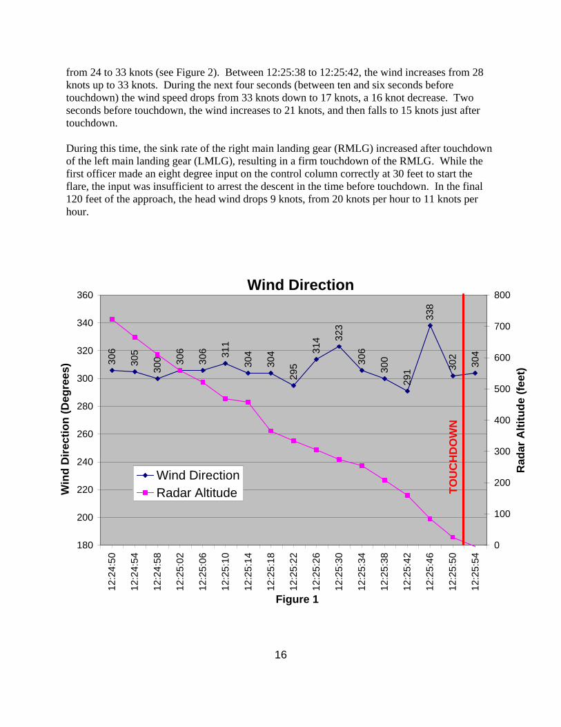
“Passengers and Crew on Cargo Aircraft”. 5. AIRWORTHINESS There were no preexisting structural problems with the aircraft, and it was airworthy at touchdown. The right main landing gear contacted the runway at approximately 14.4 feet per second which exceeded the structural limits of the landing gear. 6. FLIGHT DATA RECORDER This section is intended to provide an analysis of the data obtained from the Flight Data Recorder (FDR) installed on this aircraft. This was accomplished through a review of the FDR data and review of the FDR Study. A. Wind Recorded on the FDR During the final 62 seconds of the approach, the aircraft encountered strong, gusty winds. The wind shifted from 295 degrees to 323 degrees between 12:25:22 and 12:25:30 (see Figure 1). In the next four seconds the wind continues to shift directions, going to 338 degrees, a 47 degree shift, just six seconds prior to touchdown. The wind then shifts back to 302 degrees approximately two seconds from touchdown. At the same time, there are several wind gusts. The wind for the final minute of flight averages approximately 28 knots, with speeds ranging
16
from 24 to 33 knots (see Figure 2). Between 12:25:38 to 12:25:42, the wind increases from 28 knots up to 33 knots. During the next four seconds (between ten and six seconds before touchdown) the wind speed drops from 33 knots down to 17 knots, a 16 knot decrease. Two seconds before touchdown, the wind increases to 21 knots, and then falls to 15 knots just after touchdown. During this time, the sink rate of the right main landing gear (RMLG) increased after touchdown of the left main landing gear (LMLG), resulting in a firm touchdown of the RMLG. While the first officer made an eight degree input on the control column correctly at 30 feet to start the flare, the input was insufficient to arrest the descent in the time before touchdown. In the final 120 feet of the approach, the head wind drops 9 knots, from 20 knots per hour to 11 knots per hour.
Wind Direction
306
305
300 30
6
306 31
1
304
304
295
314 32
3
306
300
291
338
302
304
180
200
220
240
260
280
300
320
340
360
12:2
4:50
12:2
4:54
12:2
4:58
12:2
5:02
12:2
5:06
12:2
5:10
12:2
5:14
12:2
5:18
12:2
5:22
12:2
5:26
12:2
5:30
12:2
5:34
12:2
5:38
12:2
5:42
12:2
5:46
12:2
5:50
12:2
5:54
0
100
200
300
400
500
600
700
800
Wind DirectionRadar Altitude
TO
UC
HD
OW
N
Win
d D
irec
tio
n (
Deg
rees
)
Figure 1
Rad
ar A
ltit
ud
e (f
eet)

17
Wind Speed (Knots)
26
29
27
24
33 32
29
25 26
29 28
17
21
15
24
31
33
0
5
10
15
20
25
30
35
40
12:2
4:50
12:2
4:54
12:2
4:58
12:2
5:02
12:2
5:06
12:2
5:10
12:2
5:14
12:2
5:18
12:2
5:22
12:2
5:26
12:2
5:30
12:2
5:34
12:2
5:38
12:2
5:42
12:2
5:46
12:2
5:50
12:2
5:54
0
100
200
300
400
500
600
700
800
Wind SpeedRadar Altitude
B. Aileron Sampling While not a factor in the accident, the FDR group found that the parameters recorded for aileron position on this recorder does not meet the requirements of 14 CFR Part 121.344 Appendix M. The FDR is recording values 4 times per second for each aileron position; however, the update rate of the data source is not sufficient. The FDR Study found:
The values for each aileron form 6 sets of triplets followed by a doublet of repeated values over a 5 second period. This is an update rate of approximately 700 ms, not the required 500 ms rate. The Safety Board has found similar problems with other aircraft FDR systems and has issued Safety Recommendation A-03-015, which addresses the other specific aircraft with this problem, and Safety Recommendation A-03-016, which recommends that the FAA survey all other aircraft required to have flight data recorders to ensure they meet the requirements of 14 CFR Part 121.344 Appendix M.
The FAA conducted a study into the cost of complying with Safety Recommendation A-03-016. The FAA replied in a letter to the NTSB dated August 11th, 2004:
TO
UC
HD
OW
N
Win
d S
pee
d (
Kn
ots
)
Figure 2
Rad
ar A
ltit
ud
e (f
eet)

18
The FAA conducted a preliminary review of the impact of complying with this safety recommendation. To do what the Board is asking will require evaluating more than 6,500 aircraft, with an approximate cost of $3,500 to analyze each aircraft. This is an enormous economic impact on the industry. Consequently, my staff contacted your staff to discuss this safety recommendation. It was agreed that it would be more cost effective to query the aircraft manufacturers on design criteria for data collection on their individual aircraft models rather than evaluate specific aircraft for compliance with the parameter requirements of 14 CFR 121.344, Appendix M. Consequently, the FAA will request that aircraft manufacturers not covered in the response to Safety Recommendation A-03-15 provide the FAA with design criteria on their flight data recorders for obtaining Appendix M data. Upon completion of this design assessment, the FAA will be able to identify necessary changes to bring affected aircraft into compliance. I will keep the Board informed of the FAA's progress on this safety recommendation.
The NTSB responded to the FAA in a letter dated January 28th, 2004. The letter stated:
The Safety Board notes that the FAA conducted a preliminary review of the financial impact of complying with this safety recommendation. This review showed there is an enormous economic impact on the industry for collecting this information. As a more cost-effective alternative, the FAA plans to request that aircraft manufacturers provide the FAA with design criteria for their FDR systems. Upon completion of this design assessment, the FAA will identify necessary changes to bring affected aircraft into compliance. The Safety Board agrees that the FAA's proposal to query manufacturers on design criteria for data collecting on their individual aircraft models is a cost-effective alternative method of satisfying this recommendation. The Board urges the FAA to include cockpit display manufacturers in the planned design assessment. The Board believes that the involvement of these manufacturers is critical in identifying the fundamental cause of the FDR discrepancies. Pending completion of the survey of manufacturers on FDR design criteria for obtaining Appendix M data, and the identification and mandating of necessary changes to bring affected aircraft into compliance with Part 121.344, Appendix M, Safety Recommendation A-03-16 is classified "Open-Acceptable Alternate Response."
While the financial burden may be high for a study of all installed FDRs, this accident makes it clear that some additional action must be take in order to ensure that FDR systems accurately and reliably receive and record actual aircraft system performance parameters. The NTSB and FAA should reexamine this recommendation, and determine if the alternate action is truly acceptable. According to the NTSB, it has been suggested that one solution to the repeating values in the aileron parameters would be to selectively ignore several of the samples of the recorded data resulting in the aileron positions being alternately sampled. This would provide the required sample rate, but would not give good data. The FDR Study found:
19
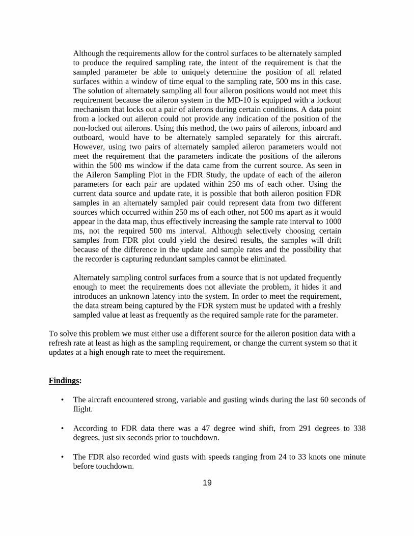
Although the requirements allow for the control surfaces to be alternately sampled to produce the required sampling rate, the intent of the requirement is that the sampled parameter be able to uniquely determine the position of all related surfaces within a window of time equal to the sampling rate, 500 ms in this case. The solution of alternately sampling all four aileron positions would not meet this requirement because the aileron system in the MD-10 is equipped with a lockout mechanism that locks out a pair of ailerons during certain conditions. A data point from a locked out aileron could not provide any indication of the position of the non-locked out ailerons. Using this method, the two pairs of ailerons, inboard and outboard, would have to be alternately sampled separately for this aircraft. However, using two pairs of alternately sampled aileron parameters would not meet the requirement that the parameters indicate the positions of the ailerons within the 500 ms window if the data came from the current source. As seen in the Aileron Sampling Plot in the FDR Study, the update of each of the aileron parameters for each pair are updated within 250 ms of each other. Using the current data source and update rate, it is possible that both aileron position FDR samples in an alternately sampled pair could represent data from two different sources which occurred within 250 ms of each other, not 500 ms apart as it would appear in the data map, thus effectively increasing the sample rate interval to 1000 ms, not the required 500 ms interval. Although selectively choosing certain samples from FDR plot could yield the desired results, the samples will drift because of the difference in the update and sample rates and the possibility that the recorder is capturing redundant samples cannot be eliminated. Alternately sampling control surfaces from a source that is not updated frequently enough to meet the requirements does not alleviate the problem, it hides it and introduces an unknown latency into the system. In order to meet the requirement, the data stream being captured by the FDR system must be updated with a freshly sampled value at least as frequently as the required sample rate for the parameter.
To solve this problem we must either use a different source for the aileron position data with a refresh rate at least as high as the sampling requirement, or change the current system so that it updates at a high enough rate to meet the requirement. Findings:
• The aircraft encountered strong, variable and gusting winds during the last 60 seconds of flight.
• According to FDR data there was a 47 degree wind shift, from 291 degrees to 338
degrees, just six seconds prior to touchdown.
• The FDR also recorded wind gusts with speeds ranging from 24 to 33 knots one minute before touchdown.

20
• Between ten and six seconds before touchdown, the FDR recorded wind speed drops
from 33 knots down to 17 knots, a 16 knot decrease.
• Two seconds before touchdown, the FDR recorded a wind increase to 21 knots, and then falls to 15 knots just after touchdown.
• The aileron position data recorded on the FDR does not comply with FAA requirements.
Recommendations:
1. The NTSB and FAA should reexamine Safety Recommendation A-03-016, which recommends that the FAA survey all other aircraft required to have flight data recorders to ensure they meet the requirements of 14 CFR Part 121.344 Appendix M, and determine if the alternate action is truly acceptable.
2. The FAA should mandate that the aircraft manufacturer should either use a different
source for the aileron position data with a refresh rate at least as high as the sampling requirement, or change the current system so that it updates at a high enough rate to meet the requirement
7. COCKPIT VOICE RECORDER
Not a factor. 8. AIRPLANE PERFORMANCE The airplane encountered strong, gusting winds in the final 60 seconds of flight. These winds produced significant, rapid changes in both the headwind and crosswind components acting on the aircraft. These rapid changes, in turn, affected the airplane performance and the ability of the flying pilot to react to the changes. DFDR data shows that a flare was begun at the appropriate height of 30 feet, but the control input was insufficient to arrest the sink rate prior to ground contact. The First Officer manipulated the aileron and rudder consistent with the crosswind that appears to have been present, i.e. left aileron with right rudder. The airplane touched down first on the left main landing gear, followed by the right. The performance group identified elevator movement from approximately 2 3/4 deg airplane nose up to 12 ¾ degree airplane nose up at about the same time that the right gear touches down. The right main landing gear contact occurred at approximately 14.4 feet per second, exceeding the structural limits of the landing gear.

21
9. MATERIALS LABORATORY REPORT Not a factor. 10. FINDINGS 1. The MD-10 program has effectively improved the capability and service life of the DC-10
airframes, however, the program does not change the flying characteristics of the MD-11 or MD-10 enough to enable them to be called the same aircraft.
2. While the MD-10 and MD-11 are certified as the same type, no changes were made to the wings, flight controls or engines of the MD-10 from the DC-10. Therefore, DC-10 wind corrections should be used for the MD-10. Using the wind additive appropriate for the MD-11 reduces airspeed safety margins on MD-10 aircraft especially at low altitude while on approach.
3. The handling characteristics of the MD-11 are distinctly different than the handling characteristics of the DC/MD-10. This is due to a longer wing with winglets, a longer fuselage and a horizontal stabilizer that is 60 percent the size of the DC-10. Additionally the MD-11 has an auto pitch trim system, Longitudinal Stability Augmentation System (LSAS) with the feature that auto trims when hand flying
4. In order to receive a common type rating, the FAA required that the MD-11 and MD-10 have flying and handling characteristics that were similar. The easiest way to accomplish this was to change the MD-11 Flight Control Computer (FCC) software to make the MD-11 fly similar to the MD-10. New FCC software, the FCC-908 load, was introduced and is required in order to fly both the MD-11 and MD-10. While most of the FCC-908 load changes have improved the handling characteristics of the MD-11, the changes have not made the MD-11 fly like the DC/MD-10.
5. Until November 2004, FedEx IOE (Initial Operating Experience) students were not required
to fly more than one of the MD-10/11 type variants (MD-11, or either the MD-10-10 or the -30). The entire IOE may well have been conducted in just one version.
6. At the time the First Officer was trained, the first time a FedEx pilot performed an MD-10
landing was in the actual aircraft, and could have been many months after completing differences training.
7. The FedEx MD10-30 simulator is not being used for Proficiency Checks (PCs) due to
considerations of the FAA-certified MD-11 and MD-10 training syllabus. 8. Many MD-11 pilots, especially those acting frequently as Relief First Officers (RFO's), have
not been able to maintain currency in the aircraft and must get their required three takeoffs and three landings in the simulator.

22
9. Certifying the MD-10 with a same type rating as the MD-11 and not requiring currency in
both aircraft has resulted in pilots going months and in some cases years between flying each aircraft. The First Officer in this accident was conducting only her third landing in the MD-10 in the preceding 12 months, including the one the day before.
10. Due to the FedEx fleet being composed largely of aircraft that started out with other carriers,
the escape slide configurations and procedures for manual deployment vary from aircraft to aircraft. This can lead to confusion or improper deployment of the escape slide system.
11. The slides on the accident aircraft were certified to a lower standard than required by current
slide requirements. These slides did not meet the current wind requirements. One slide was unusable due to fire, and the other blew under the aircraft fuselage when deployed, rendering it useless, and forcing the crew to find another means of egress from a burning aircraft.
12. Since the slide was unusable, the crew had to rely on egressing out the Captain’s and First
Officer’s clearview windows using escape tape. 13. Because of the construction of escape tape, a thin ribbon of reinforced synthetic material, one
of the crew suffered burns to the hands. If a crewmember had been incapacitated, there would have been no means to evacuate him or her safely from the burning wreckage.
14. One crewmember was injured by falling while trying to use the escape tape. 15. Prior to January 2004 there was no girt bar attached to the girt bar locking brackets at the
doorsill on the FedEx MD-10 door training equipment at the Memphis, Tennessee training facility. Without the girt bar, crews are unable to train for manual slide inflation on a door that accurately models the actual aircraft.
16. During the investigation, it was found that FedEx MD-11 and MD-10 crews were not getting
“hands-on” experience with escape slide manual inflation. A flight-training manager at FedEx stated that when the girt bar flap had been installed on the MD-10 door training equipment, the use of the manual inflation handle was not part of the Emergency Procedures Training (EPT) hands-on drill.
17. A FedEx check airman stated that he recalled that procedures for operating the manual
lanyards attached to the slide were taught during classroom instruction. He said that demonstration and practical application of those procedures were not practiced.
18. ATC informed the Chief of Airport Fire Station #33 that there were only 3 souls on board the
airplane, based solely on an erroneous assumption, not on information obtained from the flight crew or dispatch. This resulted in a smaller ARFF response in the early stages of the accident.

23
19. The Rural Metro Fire Department (RMFD), located on the FedEx ramp, had difficulties responding to the accident due to an incoming airplane on runway 27/9. ATC allowed that aircraft to land which delayed the RMFD fire truck for about 1 – 1½ minutes.
20. The aircraft encountered strong, variable and gusting winds during the last 60 seconds of
flight. 21. According to FDR data there was a 47 degree wind shift, from 291 degrees to 338 degrees,
just six seconds prior to touchdown. 22. The FDR also recorded wind gusts with speeds ranging from 24 to 33 knots one minute
before touchdown. 23. Between ten and six seconds before touchdown, the FDR recorded wind speed drops from 33
knots down to 17 knots, a 16 knot decrease. 24. Two seconds before touchdown, the FDR recorded a wind increase to 21 knots, and then falls
to 15 knots just after touchdown. 25. The wind sensor, one mile away from the accident site, recorded gusty and variable winds at
its location during the last 10 seconds of flight. 26. At the sensor location there was a 55 degree wind shift followed by another 45 degree shift at
the sensor location, during the last 10 seconds of flight. 27. At the same sensor location, wind speed drops 16 knots during the final 10 seconds of flight. 28. The aileron position data recorded on the FDR does not comply with FAA requirements. 11. SAFETY RECOMMENDATIONS ALPA offers the following Safety Recommendations to attempt to correct deficiencies identified during the course of this accident investigation. To the Federal Aviation Administration (FAA) 1. Require an immediate review of wind additives for the MD-11 and MD-10 be conducted to
insure the MD-10 is being operated safely. 2. When a second MD-10 simulator is added, it should be in an MD-10-10 configuration. 3. Require that operators of the MD-10 train so that IOE legs are flown in the MD-11 and both
MD-10 variants.

24
4. Require that operators, who fly MD-11 and MD-10 aircraft, give pilots annual recurrent training on the differences in MD-10 piloting technique if they have not flown the aircraft during the previous year
5. Require modification to the MD-10 and MD-11 windshear alert and guidance system
(WAGS) to make it active until touchdown. 6. Require that all aircraft equipped with escape slides be retrofitted with slides that meet the
current FAR 25.810 requirements. 7. Require operators and aircraft manufacturers to install an inertia reel at slide equipped doors
to function as a backup in the event of escape slide malfunction. This will allow evacuation without the risk of “rope burns” or falling to the ground. This will also aid in evacuation of passengers or crew who may have become incapacitated.
8. Require that operators install the “Emergency Evacuation Checklist” on the pilots chart
holder on both yokes. It should be printed in luminescent print to allow for visibility in low-light conditions.
9. Emergency evacuation training should be conducted by all operators on all Proficiency
Training and Proficiency Checks. 10. Require operators to add training on manual inflation of the escape slide as part of the
Emergency Procedures Training (EPT) hands-on drill. 11. Require all escape slide simulators to be configured and painted to more closely resemble the
installation in the actual aircraft. 12. Communicate with all ARFF and air traffic control tower personnel at airports that wide
body cargo aircraft operate from and convey that they sometimes transport as many as 27 persons on their wide body airplanes, many of which will be in the aft section of the plane.
13. Develop an addition to the flight training syllabus at cargo carriers that carry occupants in the
rear of the aircraft, to create awareness on the part of the crewmembers on how to deal with an emergency evacuation involving passengers occupying the seat pallets in the rear of the aircraft.
14. Verify that all airports and ARFF stations have received a copy of FAA CertAlert No. 04-01,
“Passengers and Crew on Cargo Aircraft”. 15. The NTSB and FAA should reexamine Safety Recommendation A-03-016, which
recommends that the FAA survey all other aircraft required to have flight data recorders to ensure they meet the requirements of 14 CFR Part 121.344 Appendix M, and determine if the alternate action is truly acceptable.

25
16. The FAA should mandate that the aircraft manufacturer should either use a different source for the aileron position data with a refresh rate at least as high as the sampling requirement, or change the current system so that it updates at a high enough rate to meet the requirement.

APPENDIX B
APPENDIX A
Correspondence on Common Type Rating
APPENDIX A

FEBRUARY 3,ZOOO
VIA @4ERNIGHT LETTERJane F, Garvey, AdministratorFederal Aviation AdministrationNational Headquarters
800 Independence Ave., S.W.Washington, D.C. 20591 .
.
Dear Administrator Garvey:
On behalf of tk 3fsoo Pilots it Wfesen&, the FEDEX PILOTS A~~~~\AT!oN (FPA) urgescareful deliberation and caution regarding &I Same-type rating certification for the MD-IOand the MD-l.1 akrafa. Safety is a c~~~e~f~k~~e of our organization and the pos.sibiiityof this same-type GefiifiCatkn raises significant con~efn~. Previously, we voiced &mayat the overai~ aircraft Gekfk&km pr0CeSS with NTSB Chainnan t~afl, At the time, ourcomments @pressed astonishment that ail aircraft are cefiifi& to land only on bothmain landing gear. (This is Possible onfy when there are no c r o s s w i n d s . ) T h i sdiscussion arose out Qf a meeting on the hS of a Fed& MD-1 1 aircraft during landingat Newark Airport. Sirs that time, We have bst another MD-~ 1 in a landing accident atSubic Bay, Philippines. In the intereSk of safety and preventable mishaps, we now goon record protesting the single type MD-lOOIMD-1 1 rating.
The Boeing Company, in conjunction with the kderaf Express Corporation (FedEx),has embarked upon a program that WiH ~~~VfXt being DC-JO aircraft to MD-10’s. This~onversk~~ d&&es the Position of flight engineer with, in owr opinion, i n a d e q u a t emeasures to address his or her absence, especially in an e m e r g e n c y si tuat ion.Although the FPA SuPPOflS the EXXUW~~ benefit to FedEx and accepts the conversionof the DC-I 0 aircraft, We oppose the Proposition that a single type rating on both aircraftprovides the same fevel of safety that individual type ratings provide. The differencesbetween the MD-1 1 and MD-70 are too great to w~~rrant a same-type rating. _-
The history of the Boeing MD-1 ‘! speaks for itself. It has the highest rate of fatai eventscompared to other airtjners.’ It SbuId be noted that the MD-1 1DC-IO, an aircMt with tl-b 2”’ h ighest ra te of fata! evPntS 2
is a derivative of theThe FPA believes
The MD-1 I can currentfy be dispatched with CVI& one system in “manual” m&e inacknowledgement of the high wdd~ad on the pilots in critical phases of flight. The MD-10 would a/Ways have at least One system i n “manuai.” During an e m e r g e n c y ,automation is supposed to Provide the SQJPOe Or’ the missing third pilot. Obviously, thethird pilot is not availabk On the MD-KJ or the MD-? I-. On the MD-q& .automation maynot be there either. These are very diffkdt aircraft to ffy in the best of circumstances,and the FPA maintains that safety is best served when the pilots are special&din anincjividual aircraft. _The MD-1 0. and the. MD-1 1 are not the same ‘aircraft.
Pilots that are required to fly the majority Of their carzers in the middle of the night arc;continualJy faced with the iSSLE Uf fatigue. As YOLJ are aware, pilots under supp/ementaf
ruks are not guaranteed predepafiure CreWrest and are often unsure of what time ofday 07 night they will be cakd to duty.oversight in desperate need of correction.
This inexplicable lapse in protection is anAn ~D-lO/M~l~ same-type rating w4d
have a detrimentaf impact On a tired PilUt's response time. The differences on the flight&& will have few ViSUaf Cues, but in actual aiicraft response, the differences would bestriking and potentiaily dangerous.
Pag2 2 of 3

. ‘3. k_ ,. *.
Very truly yours, .I
. 2ff4 ‘*President; FEDEX PILOTS ASSOCIATION
.
cc: Chairman Hall, National Transporktion Safety BoardCongressman James L. OberstxCongressman Ralph M. HallRobert Coweli, principal operation Inspebr, Federal Aviation &jministrationCaptain Duane Woeeh, President, Air Line Pilots AssociationCaptain Robert Miller, President, Independent Pilots AssociationCaptain Dave web FPA Safety Committee Chairmar,First Officer Dan DeLane, FPA Accident Investigation Comm#ee ChairmanEdgar N. James, Attorney .
Page 3 of 3


- . . .-- ---- . . . . -. .- ..-._ .-
. . . _ c .,- ---B.S.. -- -m-e...-... . -.- - w-L- - - . . w.
.

APPENDIX B
APPENDIX B - FAA CertAlert No. 04-01, “Passengers and Crew on Cargo Aircraft”
C E R T A L E R T
ADVISORY CAUTIONARY NON-DIRECTIVE
FOR INFORMATION, CONTACT Ben Castellano , AAS-300 (202) 267.8728
DATE: March 1, 2004 No. 04-01
TO: Airport Operators, Airport Rescue Firefighter Mgmt, FAA Airport Certification Safety Inspectors
TOPIC: PASSENGERS AND CREW ON CARGO AIRCRAFT A recent aircraft accident has demonstrated a potential problem with determining the passenger and crew loading on cargo aircraft. The incident aircraft was a cargo MD-10 (old DC-10). At the time of this incident, the ARFF crew at the airport assumed that the cargo MD-10 would have no more than 3 crew members aboard, total. When the incident occurred, it became a no notice Alert 3, without time for Air Traffic (ATCT) personnel to request the routine Alert information including “souls on board.” Arriving ARFF units were surprised to see 7 personnel egress the aircraft. A briefing with the cargo operator after the accident revealed that on its MD-10 aircraft, there could be as many as 27 personnel on board, at any time. Additionally, in some configurations personnel are located in the rear of the fuselage section. This is usually used during livestock transportation with the handlers in the rear, but may occur for other reasons. If, after the accident, the crew was unable to advise ARFF of the total personnel on board, some passengers could be trapped based on an assumption of expected and limited crew. The FAA suggests that airport operators and/or ARFF crews contact their cargo operators and explore avenues to determine the number of personnel that could possibly be expected on a particular aircraft. If possible, pre-plan with cargo operations for a way to obtain personnel manifests for incoming flights. At the minimum, expect that there could be a far greater number of personnel aboard than expected. _____________OSB ___________________ 3/1/2004 Benedict D. Castellano, Manager Airport Safety and Operations, AAS-300