ferastrau circular_cs 315
DESCRIPTION
Manual utilizare Ferastrau Circular_cs 315TRANSCRIPT

'.:-Ì
@
Operating manualGircular metal saw
cs 275 Ft
cs 315 r-i
Page 1


3.5.23.5.33.5.4
3.5.53.5.6
Operation4.1 Safety4.2 Control and indicating elements CS 275lCS 315
4.3 lnsertworkpiece....................4.4 Saw blade speed........,
4.4.1 Speed change4.4.2 Select the toothing and the shape of the toothSwitching on the machineSwitching off the machineSawing of anglesCooling
Maintenance5.1 Safety
5.1.1 Preparation5.1.2 Restarting............
5.2 lnspectionandmaintenance...............5.3 Mounting and replacing the saw blade
5.3.1 Dimensions of sawing flange
5.4 Repair........
Ersatzteile - Spare parts6.1 Ersatzteilzeichnung - Explosion drawing........,.....
6.1.1 Einzelteile - Spare parts...........
6.2 Schaltplan - Wiring diagram6.2.1 Ersatzteilliste - Spare parts list - CS 275....
6.2.2 Ersalzteilliste - Spare parts list - CS 315....
Anomalies7.1 Anomalies in the circular metal saw
Appendix8.1 Copyright...8.2 Terminology/Glossary8.3 Liability claims for defects / warranty...8.4 Note regarding disposal / options to reuse:........,
8.4.1 Decommissioning.........8.4.2 Disposal of the packaging of new devices8.4.3 Disposing of the old device8.4.4 Disposal of electrical and electronic components8.4.5 Disposal of lubricants and coo|ants..............
Direction of the saw teeth ..........Check the oil level in the worm gear.............Fill in coolant.................
Power supplyCheck the running direction of the saw blade
24
24
25
25
25
26.26
4
4.54.64.74.8
272828
2830
3031
32
343434
35
3B
39
39
5
64041
4344
47
7
I50
5'1
5'1
52525353
535354
5454
5556
DisposalRoHS, 20021951CE.......
Product follow-up
8.5
8.68.7
8.8 EG-Declaration of Conformity....
Page 3

1 Safety
H
Glossary of symbols
ûg¡ gives additional indications
à calls on you to act
enumerations
This part of the operating manual
' explains the meaning and use of the warning references contained in the operating manual,. explains how to use the circular metal saw properly,
' highlights the dangers that might arise for you or others if these instructions are not obeyed,. tells you how to avoid dangers.
ln addition to this operating manual please observe. applicable laws and regulations,. legal regulations for accident prevention,
European standards must be observed during installation, operation, maintenance and repair ofthe circular metal saw.
lf European standards are not applied in the national legislation of the country of destination, thespecific applicable regulations of each country must be observed.
Where necessary the required measures must be taken to comply with the specific regulation ofeach country before the circular metal saw is first used.
ALWAYS KEEP THIS DOCUMENT CLOSE TO THE CIRGULAR METAL SAW FOR FUTUREREFERENCE.
INFORMATION
lf you are not able to solve a problem using this manual, please do not hesitate to contact us forfurther professÍonal advice:
Page 4

1.1 Safety warnings (warning notes)
1.1.1 Classification of hazards
We classify the safety warnings into various levels. The table below gives an overview of the
classification of symbols (pictograms) and warnings for the specific danger and its (possible)
consequences.
ln the case of specific dangers, we replace the pictogram by
rotating parts.
or
general danger with a warningof
injuries tohands,
hazardous elec-trical voltage,
PictogramAlarm expres-
sionDefi nition/Consequences
lmminent danger that will cause serious injury or death topersonnel.DANGER!
WARNING!Risk: A danger that might cause serious injury or death topersonnel.
Danger or unsafe procedure that might cause injury topersonnel or damage to property.CAUTION!
Situation that could cause damage to the machine andproduct and other types of damage.
No risk of injury to personnel.ATTENTION!
o INFORMATION
Application tips and other important or useful informationand notes.
No dangerous or harmful consequences for personnel orobjects.
Page 5

1.1.2 Other pictograms
Caution
slide risk!
Use protectivegloves!
1.2
Pull the mainsplugl
Wear a safety suit!
as@@(O@ß0 ffi
Activation forbid-den!
Use protectiveboots!
Use protectivegoggles!
Protect the envi-ronment!
Use ear protec-tion!
Contact address
Proper user
Usage
WARNING!
lmproper use of the circular metal saw. w¡ll endanger personnel,. w¡ll endanger the machine and other material property of the operator,. may affect proper operation of the machine.
The circular metal saw is designed and manufactured to be used in environments where there isno potential danger of explosion.
The circular metal saw is designed and manufactured to saw cold metals, cast materials andother plastic materials that are not harmfulto health and do not generate dust.
The circular metal saw must not be used on wood.
The pieces to be cut need to be of a shape that will allow them to be securely attached in thework holder vice and ensure that the piece does not come loose when it is being sawed.
The circular metal saw must only be installed and operated in a dry and well-ventilated place.
Page 6

1.3
WARNING!
Very serious injury.
It is forbidden to make any modifications or alterations to the operating values of the cir-cular metalsaw! These could endanger personnel and cause damage to the machine.
Possible dangers caused by the circular meta¡ saw
The circular metal saw is state-ofthe-art, but there is a residual risk, as the circular metal saw isworking with
. electrical voltage and currents
. a running circular metal saw blade.
We have used construction resources and safety techniques to minimise the health risk to per-
sonnel resulting from these hazards.
lf the circular metal saw is used and maintained by staff who are not duly qualified, there may be
a risk resulting from incorrect operation or unsuitable maintenance.
INFORMATION
All staff involved in assembly, commissioning, operation and maintenance must
. be duly qualified,
. follow this operating manual.
ln the event of improper use
. there may be a risk to the staff,
. there may be a risk to the circular metal saw and other material property,
. the proper operation of the circular metal saw may be affected.
Disconnect the circular metal saw whenever cleaning or maintenance work is being carried out
WARNING!
THE CIRCULAR METAL SAW MAY ONLY BE USED WITH THE SAFETY DEVICES ACTI.VATED.
Disconnect the circular metal saw whenever you detect a failure in the safety devices orwhen they are not fitted!All additional installations carried out by the operator must incorporate the prescribedsafety devices.Being the machine operator, this will be your responsibility!o9 "Safety devices" on page 9
1.4 Qualification of personnel
1.4.1 Target group
This manual is addressed to
. users,
. operators,
. maintenance staff.
The warning notes therefore refer to both operation and maintenance of the circular metal saw.
Determine clearly and irrevocably who will responsible for the different activities on the machine(use, maintenance and repair),
Vague or unclear assignment of responsibilities constitute a safety hazardl
Page 7

Obligationsof the opera-
tor
Obligationsof the user
Additionalqualification
require-ments
1.5
Always disconnect the circular metal saw from the power supply and secure the circular metalsaw against restarting.
Authorised personnel
WARNING!
Incorrect use and maintenance of the circular metal saw constitutes a danger for thestaff, objects and the environment.Only authorised personnel may operate the circular metalsaw!
The only staff authorised to use this machine and perform maintenance on it are trained andinstructed technical staff working for the operator and manufacturer.
The operator must
. train staff,
. instruct staff regularly (at least once a year) on- all safety standards that apply to the machine,
- operation,
- accredited technical guidelines,. check staff's understand,. document training/instruction,. require staff to confirm participation in training/instruction by a signature,
' check whether the staff are aware of safety and of dangers in the workplace and whetherthey observe the operating manual.
The user must
. have received training in operation of the circular metal saw,
. know the function and principle of operation,
. before the machine is first used- have read and understood the operating manual,- be familiar with all safety devices and regulations.
For work on the following machine components there are additional requirements:
' Electrical components or devices: This work must only be carried out by a qualified electri-cian or person working under the instructions and supervision of a qualified electrician.Before carrying out work on electric components or operating units the following measuresmust be taken, in the order given.- Disconnect all poles
- Ensure that the machine cannot be turned on again
- Check that there is no voltage
User pos¡t¡ons
The user must stand in front of the circular metal saw
INFORMATION
The mains plug of the circular metal saw must be freely accessible
Page I

1.7
1.6 Safety measures during operation
CAUTION!
Risk due to inhaling of health hazardous dusts and mist.
Dependent on the material which need to be processed and the used auxiliaries dustsand mist may be caused which might impair you health.
Make sure that the generated health hazardous dusts and mist are safely sucked off atthe point of origin and is dissipated or filtered from the working area. Use an appropriatesuction unit.
CAUTION!
Risk of fire and explosion by using flammable materials or cooling lubricants.
Take additional preventive measures in order to safely avoid health hazards beforeprocessing flammable materials (e.9. aluminum, magnesium) or before using flammableadditives (e.9. spirit).
Safety devicesUse the circular metal saw only with properly functioning safety devices.
Stop the circular metal saw immediately if there is a failure in the safety device or if it is not func-tioning for any reason.
It is your responsibility!
lf a safety device has been activated or has failed, the circular metal saw must only be usedwhen
. the cause of the failure has been removed,
. it has been verified that there is no resulting danger for the staff or objects.
WARNING!
The separating protective equipment which is made available and delivered together withthe machine is designed to reduce the risk of workpieces or fractions of them whichbeing expelled, but not to remove them completely.
WARNING!
lf you bypass, remove or override a safety device in any other way, you are endangeringyourself and other staff working with the circular metal saw. The possible consequencesare:. damage as a result of components or parts of components flying off at high speed,. contact with rotating parts,. an electrocution.
Page I

The circular metal saw includes the following safety devices:
. a protective cover on the saw blade
The saw blade of the circularmetal saw is equipped with aprotective cover. The protec-tive cover covers the circula-tory saw blade.
WARNING!
Danger of injury! The teethof the saw belt are sharp.Take great care whenremoving the rear cover tochange the saw belt.
Wear protective gloves.
Rear cover
1.7.1 Lockable main switch
A lockable main switch can be secured bya padlock in the position "0" against switch-ing on by mistake or unauthorized.
The power supply is interrupted by switch-ing off the main plug.
Except for the positions which are markedby the ideogram in the margin.
lllustr.: 1-1 : Rear cover
Main switch
WARNING!
Dangerous voltage even if the main switch is being switched off. ln the positions of theideogram marked in the margin there might be voltage even if the main switch is beingswitched off.
Page 1 0

1.7.2 EMERGENGY-STOP button
The EMERGENCY-STOP button turns thecircular metal saw off.
INFORMATION
After actuation turn the EMERGENCY-STOP button clockwise in order to turn the e¡,¡enceNcy-sropcircular metal saw on again. button
lllustr.: 1-3: EMERGENCY-STOP button
1.7.3 Prohibition, warn¡ng and mandatory labels
INFORMATION
All warning labels must be legible.
Check them regularly.
Positions of labels on the circular metal saw:
lllustr.: 14: circular metal saw CS 315
Check the circular metal saw at least once per shift. lnform the person responsible immediatelyof any damage, defect or change in operating function.
Check all safety devices
. at the beginning of each shift (with the machine stopped),
. once a week (with the machine in operation),
. after every maintenance and repair operation.
Check if the prohibition, warning and information labels and the markings on the circular metalsaw
. can be identified (if not, clean them),
. are complete.
Individual protection gear
For certain work individual protection gear is required. This includes
. safety helmet,
1.8
Page 11

1.9
. protective goggles or face guard,
. protective gloves,
. safety shoes with steel caps,
. ear protection.
Before starting work, make sure that the prescribed individual protection gear is available at theworkplace.
CAUTION!
Dirty or contaminated personal protection gear can cause disease. Glean your personalprotection gear after each use, regularly, at least once a week.
Personal protect¡on gear for special work
Protect your face and eyes: During all work, and specifically work during which your face andeyes are exposed to hazards, a safety helmet with a face guard should be worn.
Use protective gloves when lifting or handling pieces with sharp edges
Wear safety shoes when fitting, dismantling or transporting heavy components
Safety during operat¡onln the description of work with and on the circular metal saw we highlight the dangers specific tothat work.
WARNING!
Prior to activating the circular metal saw please double-check that this will. not endanger anybody,. not cause any damage to property.
Avoid unsafe working practises:
. Make sure yourwork does not endanger anyone.
. The instructions in this manual need to be observed during assembly, handling, mainte-nance and repair.
' Do not work on the circular metal saw if your concentration is reduced, for example, becauseyou are taking medication.
' Observe the rules for preventing accidents issued by your association for the prevention ofoccupational accidents and safety in the workplace or other inspection authorities.
. Stay at the circular metal saw until all rotating parts have come to a halt.
' Use prescribed protection gear. Make sure to wear a well-fitting work suit and, where neces-sary, a hairnet.
. lnform the inspector of any danger or failure.
Page 12

1.10
Report anddocument
any changes
Safety during maintenance
lnform operating staff in good time of any repair and maintenance work.
Report all safety-relevant changes or performance details of the circular metal saw. Documentall changes, have the operating manual changed accordingly and train the machine operators.
1.10.1 Disconnecting the circular metal saw and making it safe
Unplug the circular metal saw from the mains before beginning any maintenance or repair work,
Place a warning sign on the machlne.
1.10.2 Using lifting equ¡pment
WARNING!
Use of unstable lifting equipment and load-suspension devices that break under load cancause very serious injuries or even death.
Check that the lifting and load suspension gear. is of sufficient load capacity,. in pedect condition.Observe the preventing of accidents issued by your association for the prevention ofoccupational accidents and safety in the workplace or other inspection authorities.
Hold the loads properly.
Never walk under suspended loads!
1.10.3 Mechanicalmaintenancework
Remove all protection and safety devices before beginning maintenance work and re-installthem once the work has been completed. They include:
. covers,
. safety indications and warning signs,
. earth (ground) connection.
lf you remove protection or safety devices, refit them immediately after completing the work.
Check that they are working properly!
Page 13

1.11
1.12
Accident reportlnform your superiors immediately in the event ofaccidents, possible sources of danger and any actions which almost led to an accident (nearmisses).
These near misses can have many causes.
The sooner they are notified, the faster the causes can be eliminated.
INFORMATION
ln the descr:iption of the execution of work with and on fhe circular metal saw, we highlight thedangers specific to that work.
Electrical systemHave the machine andlor the electric equipment checked regularly, and at least every sixmonths.
Eliminate immediately all defects such as loose connections, defective wires, etc.
A second person must be present during work on live components, to disconnect the power inthe event of an emergency.
Disconnect the circular metal saw immediately if there are any anomalies in the power supplyl
uF "Maintenance" on page 33, le 'Wir.ing diagram" on page 39
ug lllustr.: l-1: "Rearcovef'on page 10

S ä9 ebla ttd urch messer: Ø 275x2.o ñmDrehzahl 48/96 O/min
Max. öffnungsweite: 110mmMotorleistung: 2.0/1.4 KW,400 Volt -
cs 275ACI{TUNG I
Vor InbËtÍebnahrne dëf;!lasrhire leserr Sre aiie'r cherhrltshinvíér5ê:
on â, o o
"u o
^,o l4t u o *uo ^,n lQp u o
^ ^
4 s"@, o,ao. ^ W"o*ro ^. lâruo ^^Masch, Nr
ZN ncHru¡rc ADatum
1.ffi # {$ ,,r,j$ ie; & A, fg201
2 Technical data
2.1 Type plate
The following information gives the dimensions and weight and are the manufacturer's author-ised machine data.
2.6 Speed of saw blade cs 275 cs 315
Two-step drive engine [m/minl 48 96 19 38
Sägeblattdurchmesser: ø315x2.5ñmDrehzahl 19/38 U/¡i¡Max, öffnungsweitel 14ommMotorle¡stun9: L.5lO.75KW,400Volt-
2r)1
o' â, o,uo ^^ l4l, o*, o ^, lâr, o ^ ^
o t"ru7ox7o m m l4luo*, 0,, ^ lâr, o,-
cqg'{g} {-BJ {.iÞ {.# æ A m¿N ncHruruc zN
Masch, Nr,
Datum
ÀCHTUN G!
Vor lnbêtrìebn.-rhne dér14asclìrrÉ iesen Sie die-<r
c h e rh e rts h ì n lTe rse
2.2 Power connect¡on cs 275 cs 315
Connection
cooling pump
400V -50H22KWl1,4KW
400V -50H21,5 KW/ 0,75 KW
400V -50H2; 0,4 KW
cs 275 cs 3152.3 Cutting range
0o round, max 60 mm 70 mm
0 o rectangular, max. '100 x 60 mm 90x80mm
o o square, max. 60x60 70x70
60 mm 70 mm450 round, max.
450 rectangular, max. 70x60mm 80x70mm
450 square, max. 60x60 70 x70
Cutting angle -450-+450
2.4 General
Cutting angle adjustment
cs 275 cs 315
over turnable bearing block
Feed manually
Material tension manual in the quick-action vice
2.5 Dimensions cs 275 cs 315
u9 "Dimensions of sawing flange" on page 39
Range vice 110 mm '145 mm
Page 1 5

2.7 Environmentalconditions
Temperature
cs 275 cs 315
5-35'C
Humidity 5-80%
cs 275 cs 3152.8 Operating mater¡al
Helical gear Mobilgear 629, viscosity 40'C 150 mm2/s ,
at'100"C'16 mm2is
tso vG 150
Spindle of the machine vice Commercial heavy grease
Plain bearing Commercial heavy grease
Blank steel parts e.g. machine oil (Mobil oil, Fina, ...), motor oil, motor oil isacid-, stain- and resin-free.
2.9 EmissionsThe level of noise (emission) emitted by the circular metal saw is less than 80 dB(A).lf the circular metal saw is installed in an area where various machines are in operation, theacoustic influence (emission) on the operator of the circular metal saw may exceed the legallypermitted peak value of 85 dB(A) in the workplace.
INFORMATION
This numeric value had been measured on a new machine under conventional operating condi-tions. Depending on the age or wear of the machine, the noise behavior of the machine mightchange.
Furthermore, the extent of the noise emission is also depending on manufacturinginfluence factors, such as speed, material and clamping conditions.
INFORMATION
The mentioned numericalvalue is an emission level and not necessarily a safeworking level.
Unless the degree of noise emission and the degree of noise disturbance are depending on oneanother it is not possible to use it in order to reliably determine if it is necessary to take furtherpreventive measures or not.
The folfowing factors influence the actual degree of the noise disturbance of theoperator:
. Characteristics of the working chambe¡ e.g. size or damping behavior,
. Other noise sources, e.g. the number of machines,
. Other processes proceeding nearby and the period during which the operator is exposed tothe noise.
Furthermore, the admissible pollution level may be different from one country to another due tothe national regulations.This information regarding the noise emission should allow the operator of the machine to per-form a better evaluation of the endangerments and risks.
Page 16

Ao
CAUTION!
The machine operator has to wear an appropriate ear protection depending on the overallstress caused by noise and on the basic limit values.We generally recommend using a sound and ear protection.
2.10 Dimensions CS 275
Sdwep nkU Centn of gravity
Getl{üt/Wbigffi m5 [g
.r ^
a f EtL
0 6
\#I
ltç
9fi
Ø
Page 1 7
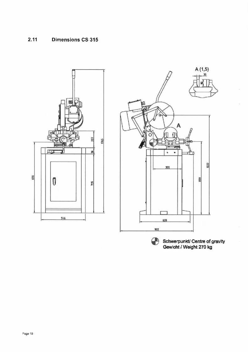
2.11 Dimensions CS 315
e
A (1,5)
Schwerpunkt/ Centre of gravityGewicïrt / Weight 27t kg
trtr==
0 q
Ir èo
¡Eq
l-l F
Page 18

3.1
3 Assembly
INFORMATION
The circular metal saw comes pre-assembled
Extent of supplyWhen the machine is delivered, immediately check that the circular metal saw has not beendamaged during shipping and that all components are included. Also check that no fasteningscrews have come loose.
INFORMATION
ln the default delivery volume, no saw blade is included. lf required, you can order saw blades ofthree different toothings. ne "Spare part list" on page 37
3.2 Transport
O Center of gravity +o Attachment positions (marking the positions for
the attachment position gear)
Prescribed transport position (marking the topside)
o
11O Means of transportation to be used
o Weights
WARNING!
Severe to lethal injuries due to machine parts tilting over or falling down from forklifttrucks or transport vehicles. Please follow the instructions and indications on the trans-portation box:. Center of gravity. Attachment positions. Weighús. Means of transportation to be used. Prescribed transport position
WARNING!
Use of unstable lifting equipment and load-suspension devices that break under load cancause very serious injuries or even death.
Check that the lifting and |oad suspension gear. is of sufficient load capacity,. in perfect condition.
Pagè 1 I

Observe the preventing of accidents issued by your association for the prevention ofoccupational accidents and safety in the workplace or other inspection authorities.Hold the loads properly.
Never walk under suspended loads!
3.3 Storage
ATTENTION!
lmproper storage may cause important parts to be damaged or destroyed.Store packed or unpacked parts only under the intended environmental conditions.Please follow the instructions and indications on the transportation box:
O Fragile goods (goods require careful handling)
O Protect against humidity and humid environments
ts "Environmentalconditions" on page 16
o Prescribed position of the packaging box (markingthe top side - arrows pointing upward)
o Maximum stacking height
Example: non-stackable - do not pile any furtherpackaging boxes on top of the first packaging box
T
11
XI
Page 20

3.4.1
3.4 lnstallation and assembly
Requirements of the installation site
Organise the work area around the circular metal saw in accordance with local safety regula-tions. rg "Dimensions" on page 15
Operation, maintenance and repair in the work area must not be hindered.
INFORMATION
The mains plug of the circular metal saw must be freely accessible.
Fasten the substructure of the circular metal saw GS 275 on the floor
) Fasten the substructure on the floor with shear connector screws M10.
m
47fl
Machine substructureFastening holes
Page 21


3.4.4 Mount the saw on the machine substructure
ATTENTION!
Danger of crushingand overturning.Proceed with cautionduring the workdescribed below.
CAUTION!
The circular metal sawneeds to be mountedon the machine sub-structure by at leasttwo persons.
l\4achine substructure
Hexagon socketscrew
lllustr.: 3-3: Mount the saw on the machine substructure.
à Put the circular metal saw on the machine substructure.
Ð Fasten the circular metal saw with the hexagon socket screws on the machine substructure
3.4.5 Mount the lever arm
) Remove the screw cap on thesaw head.
Ð Mount the lever arm on the sawhead,
à Set up the lever arm.
à Counter the lever arm attachedto the hexagonal nut.
t Connect the cable connectionwith the operating element.
Screw cap
Hand-actuatedauxiliary switch
Lifting arm
Operating element
Connecting cable-hand-actuated
auxiliary switch
Hexagonal nut
Fitting connectingcable
lllustr.: 34: Mount lever arm
Page 23

3.4.6
3.5
3.s.1
3.5.3
Mount the saw blade
> Mount your saw blade rg "Mounting and replacing the saw blade" on page 38
First use
WARNING!
Personnel and equipment may be endangered if the circular metal saw is first used byinexpert staff.We do not take liability for any damage caused by incorrect commissioning.
Checking
) Check the following.
ATTENTION!
Danger of cutting! Proceed with caution during the work described below. Use the pre-scribed protection equipment.
3.5.2 Direction of the saw teeth
; Check the direction ofthe saw teeth. The sawteeth need to be ori-ented in the direction ofthe illustrated arrow.
Running direction
)
Saw blade
lllustration: 3-5: Running direction of saw blade
Check the oil level in the worm gear
à Check the oil level in the worm gear of the circular metal sawtg "Check oil level, change gear oil." on page 35
ì Fill in gear oil, if required.
Page 24

3.5.5
3.5.4 Fill in coolant
CAUTION!
Danger of destroying the pump by dry running.When the circular metalsaw is switched on, the coolant pump is switched on.The pump is lubricated by coolant.Do not operate the pump without coolant.rø "Filling in / Rinsing / Replacing" on page 37
Power supply
Connect the mains plug of the circular metal saw with your power supply. Control the fusing(fuse) of the power supply according to the technical indications for the power input of the circu-lar metal saw.
INFORMATION
For the connection, a 400V-16 A connection cable needs to be connected
CAUTION!
lmperatively make sure that all 3 phases (L1, L2, L3) are connected correctly.Most of the defects on motors are resulting from wrong connections. For insúance, if amotor phase is not correctly clamped or connected to the neutral conductor (N).This may cause:. That the motor is becoming hot very rapidly.. lncreased motor noises.. The motor has no power.
lf the machine is wrongly connected the warrantee will become null and void.
3.s.6 Check the running direction of the saw blade
CAUTION!
Mind the rotary field!The saw blade is running clockwise.Gheck the turning direction of the circular metal saw. The circular metal saw has to turnin direction as described in ta lllustration: 3-5: "Running direction of saw blade" onpage24.lf the turning direction is wrong, please exchange two of the three phases on your cableconnection or on your power supply.Make sure that the turning direction of any other power supply is not wrong. ss' "Qualifi-cation of personnel" on pageT
o@
Page 25

4 Operation
4.1 Safety
Use the circular metal saw only under the following conditions:
. The circular metal saw is in proper working order.
. The circular metal saw is used as prescribed
. The operating manual is followed.
. All safety devices are installed and activated.
Any anomalies should be eliminated immediately, Stop the machine immediately in the event ofany abnormality in operation and make sure it cannot be started up accidentally or withoutauthorisation.
Notify the person responsible immediately of any modification.
r8 "Safety during operation" on page 12
4.2 Control and indicating elements CS 275lCS 315
Hand-actuated auxiliary switch(oN/ oFF)
Lever arm
Main switch
EMERGENCY-STOP button
Machine viceStep switchsaw blade speed
Locking lever cutting angle Oil levelworm gear
Machine stand
Page 26
lllustration: 4-1 : circular metal saw CS 315

4.3 lnsert workpieceThe machine vice servesas clamping device ofthe workpiece.
The machine vice con-sists of
. the working table,
. the clamping jaws,
. the hand wheel.
The clamping jaws at thefront and back aremoved simultaneously,this way the machinevice will clamp the clampparts centrically.
Ð lnsert the workpiecewhich needs to besawed into themachine vice.
ATTENTION!
Danger of overturning of thecircular mefal saw if themachine substructure hadnot been fixed to the floor.
Support long workpiecesbefore pushing the piece tobe cut into the machine vice.
à Turn the hand wheelto theright untilthe workpiece isfirmly clamped.
GAUTION!
Make sure if the workpiece isreally firmly clamped.
lllustralion: 4-2: Machine vice
Workpiecè
Workpiece
Material stand
Workpiece
Hand wheel
lllustration: 4-3: Machine vice
lllustration: 4-4: Hand wheel
Page 27


affD 10 30
f tl 1._JL- o 1 2 3 4 5-3
4
à oõ
I ao
12 o
t
t5 a
50 Massive material
Toothing
lllustration: 4-6: Table for toothing
Example:
Profile materialwall thickness 3 mm = toothing 10
Massive material diameter 40 mm = toothing 12
dD
Page 29

\ ) connect the mains plug with the power supply
4.5 Switching on the machine
à Main switch on
) Select speed level ,,1" or,,2"
à Actuate the hand-actuatedswitch at the handle of thelever arm.
9 Pull the lever arm down-ward towards the workpiece
4.6 Switching off the mach¡ne
> Push the lever arm upward.
) Release the hand-actuatedauxiliary switch at the han-dle of the lever arm.
à Switch the step switch to theposition ,,0".
Ð Main switch off.
lllustration: 4-7'. Hand-acluated auxiliary switch an step switch
Hand-actuated aux-iliary switch
Lever arm
Step switch
Hand-actuated auxil-iary switch
Lever arm
Step switch
lllustration: 4-8: Hand-actuated auxiliary switch and stepswitch
Page 30

4.7 Sawing of anglesThe circular metalsaw can be turned from -45" to 45' in order to allow angular saw cuts.
Angle scale
Locking lever cutting angle
lllustration: 4-9; Setting of angle cut
GAUTION!
Make sure that the saw ís clean and free of chips in the slewing area before adjusting it.
) Loosen the locking lever.
å Turn the saw to the required cutting position with the help of the angle scale.
à Retighten the locking lever
Ð Move the locking lever tothe right in order torelease the bearingblock.
à Adjust the saw to therequired position with thehelp of the angle scale.
à Move the locking lever tothe left in order to rec-lamp the bearing block,
lllustration: 4-10: Releasing clamping lever
Page 31

4.8 Gooling
Coolant pump
Coolant tank
Filling quantity aboutI litres
ATTENTION!
Damage to the pump in the event of dry running.When the circular metalsaw is switched on the coolant pump is switched on.The pump is lubricated by the coolant. Do not start up the pump without coolant.
à Turn the dosing stop valve in direction of the coolant hose until the coolant penetrates.
By the turning move high temperatures are generated at the lip of the tool by the occurring fric-tion heat.
By cooling with an appropriate coolanllubricant agent you will achieve better working resultsand longer tool life of the saw blade.
Dosing stop valve
(Flow blocked)
Coolant hose
lllustration: 4-l nt app
INFORMATION
Use a water-soluble and non-pollutant emulsion as a cooling agent. This can be acquired fromauthorised d istributors.
Make sure that the cooling agent is properly retrieved.
Respect the environment when disposing of any lubricants and cooling agents.
Follow the manufacturer's disposal instructions.
Page 32

5 Maintenance
ln this chapter you will find important information about
. inspection,
. maintenance,
. repair.
The diagram below shows which of these headings each task falls under,
lllustration: 5-1 : Maintenance - definition according to DIN 31051
ATTENTION!
Properly-performed regular maintenance is an essential prerequisite for. safe operation,. fault-free operation,. long service life of the machine and. the quality of the products you manufacture
lnstallations and equipment from other manufacturers must also be in optimum condition
ENVIRONMENTAL PROTECTION
Make sure that when working on the worm gear and on the coolant tank. collection tanks are used where the collecting capacity is appropriate for the quantity
of liquids which needs to be collected.. any spilt liquids and oils are not spilt on the ground.
Clean up any spilt liquid or oils immediately using proper oil-absorption methods and dispose ofthem in accordance with current legal requirements on the environment.
Gleaning up sp¡llages
Do not re-introduce liquids spilt outside the system during repair or as result of leakage from thereserve tank: collect them in a special vessel to be disposed of,
Disposal
Never dump oil or other pollutant substances in water inlets, rivers or channels,
MAINTENANGE
Inspection Maintenance Repair
Measu h cleani
Testing Fine cleaning Replacing
Gonserving Adjusting
Lubricatin
Comp
Readjusting
Page 33

Used oils must be delivered to a collection centre. Consult your superior if you do not knowwhere the collection centre is.
5.1 Safety
WARNING!
The consequences of incorrect maintenance and repair work may include:. Very serious injury to staff working on the machine,. damage to the machine.
Only qualified staff should carry out maintenance and repair work on the machine
5.1.1 Preparation
5.1.2
WARNING!
Only carry out work on the machine if it has been unplugged from the mains power sup-ply.
Attach a warning label.
Restarting
Before restarting, run a safety check.
WARNING!
Prior to activating the machine please double-check that this will. not endanger anybody,. not damage the machine.
Page 34

5.2 lnspection and maintenanceThe type and extent of wear depends to a large extent on individual usage and service condi-tions. For this reason, all the intervals are only valid for the authorised conditions.
WHAT?
(l)oõa_o)'õ s)v0)Êo)PEo5
HOW?
Replace the lubricating oil in the worm gear.Regularly check the oil level on the sight glass.The oil level has to reach at least the middle of the sight glass.
Charg¡ng hole
Worm gear
Oil sight glass
Drain hole
lllustration: 5-2: Oil level worm gear
o INFORMATION
The filling quantity amounts to about 0.5 litresType of the gear oil, ¡s "Operating material" on page 16
INTERVAL
every srxmonths
WHERE?
(5(¡)o)Eo
=
every sixmonths
Eq)
th
îJ)
(úooo)tu
f¿oo)EO
Check the electrical devices / components of the circularmetalsaw.
s€ "Qualification of personnel" on page 7
as required
o)L
-coo
o)c_co(U
E(¡)Eo)cc(!o)
O
) Clean the machine with an appropriate cloth and providerust protection with a conserving type of oil.
u9 "Operating material" on page 16
Page 35

INTERVAL
as required
WHERE?
o)C)
WHAT?
0)c)
c)!
o)cc(úoO
HOW?
; Regularly remove the chips which are accumulating belowthe clamping jaws.
) To do so, use a thin, flat brush.
@CAUTION!
Never clean the vice with compressed air.
as required
l¿oo_oO)c(úo-oo-o
o)(Ilo-o=J
Lubricate the arbor of the bearing block
Lubricat¡ng nipple
Arbor
Bearing block
lllustration: 5-3: Bearing block
as required
oo
oc_c(U
_9!co
U)
Lubricate the spindle of the machine vice at the provided lubricat-ing nipples.Type of lubricating oil, s€ "Operating material" on page 16
as required
Þ(úoEì(Uth.Yoo-oo,cõo
adjust-ing the
endposition
The end position of the saw blade shall be positioned belowthe support face of the machine vice.
à Adjust the end position of the saw head with the screw.Refasten the counternut after readjusting it.
Mechanical end posi-tion of the saw arch
adjusting screw
lllustr.5-4: end position saw arch
Page 36

(')c-õ
_qo_q)É.
cf,cu,cEcg,c
iL
The coolant pump is almost maintenaRce-free.. Replace the cooling agent regularly, depending on ugagê.. Rinse the coolant pump when using coolants which leave resi-
dues.. ln order to exchange the coolant tiquid, pump it into an appropri-
ate collecting vessel and refillthe coolant liquid.
o INFORMATION
The filling quant¡ty amounts to about I litres. Thusthe tank is filled about 213 ol its fillíng capacity.
oE(Ü
a=GU)
o).É.
o)tr'õ(úõ-ot,
$€ r¡u¡orn,'ng and r-eplacing the saw blade" on pagè 38
o INFORMATIONI
The spindle bearing is prelubricated. No lubricating is required

5.3 Mounting and replacing the saw blade
Disconnect the circular metal saw from the electrical supply.
us "Disconnecting the circular metal saw and making it safe" on page 13
ATTENTION!
Danger of cutting,please proceed care-fully when perform-ing the belowdescribed works. Usethe prescribed per-sonal protective gear.
+ Switch the stepswitch to the position0.
à Disconnect themains plug.
Ð Adjust the saw to themaximum top.
Please proceed care-fully when performingthe below describedworks.
Step switch
Cylinder screw
Cutting flange
She s
lllustration: 5-5: Mounting and replacing the saw blade
) Push the shells of the protective device apart.
à Loosen the socket screw M8 from the sawing spindle and remove the cutting flange.
à Remove the sawing blade.
) Thoroughly clean the sawing spindle and the flange.
) Reassemble theparts in reversesequence.
GAUTION!
à Mind the turningdirection of the sawblade.
I Check that the sawis correctly set.
) Close the protectivehood again.
Saw blade
lllustration: 5-6: Mounting and replacing the saw blade
à When mounting the saw blade, make sure that the saw blade is correctly positioned on theflange of the spindle.
Page 38
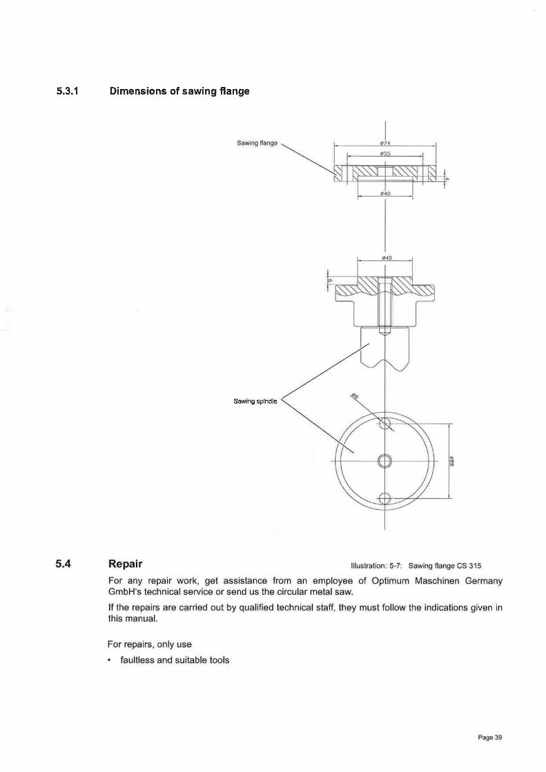
5.3.1 Dimensions of sawing flange
Sawing spindle

6 Ersatzteile - Spare parts
6.1 Ersatzteilzeichnung - Explosion drawing
Abb.6-1 : Übersicht Metallkreissäge - Overview saw - CS 275lCS 315
I¿
D
I
Page 40

6.1.1 Einzelteile - Spare parts
@A lû,60:lI
D (0.s1
Abb.6-2: Vorderansicht - Front view - CS 2751 CS 315
(0,60rlJ
C (0.60'11I
ì
,à
Abb.6-3: Hinteransicht - Opinion behind - CS 2751 CS 315
Page 41

A
A (0,40:11
Abb.6-4: Schnellspannschraubstock - Machine vice - CS 27slCS 315
Page 42
Abb.6-5: Maschinenunterbau - Machine substructure - CS 275lCS 315

- ¿
J
i
6.2 Schaltplan - Wiring diagram
5-_ã
a0
ce¿d
ÉtoEI
¡
Ëgtr :9
r
)-
F
F I
L.ôp
r
Abb.6-6: Wiring diagram
ãr
.J
Page 43

6.2.1 Ersatzteilliste - Spare parts list - CS 275
Menge GrÕsse Art¡kelnummertioo-
Bezeichnung DesignationQty. S¡ze Item no
1 n Socket-head cap screw E MsX1O2 Cover3 Unterlegscheibe Washer t¿54 Kühlmittelschlauch Cooling agent hose Ø1t)5 Kûhlm¡ttelschlauch Cooling agent hose Ø12
u Socket-head cap screw 4 N¡5x1 0
ts Washer 4 ø5Reducer / Hose clip
9-1 Hose clamp 410 Electrical box
1 0-l Abdeckblech Cover plate
11 u Socket-head cap screw 4 Môx2011-1 Unterlegscheibe Washer 4 Ø612 Zylinderschraube SocKet-head Cap screw 4 M5x20
12-1 Unterlegscheibe Washer 4 Ø613 ng PG-screw connection b't4 Maschinenunlerbau Machine stand 1
't5 Ki.r hlmittelbehälter Coolant tank 1
16 Reducer 1
1t Grundplatte Baseplate 1
16 Rrng Ring 1
19 Threaded part 1
20 Hebel Lever 1
21 GflÎf Handle 1
22 Washer 2 Ø1023 Spannmutter I rghten¡ng nut 1
24 Mutter Nut 2 M825 Zylinderschraube SocKet-head cap screw 2 M8x4526 Sechskantschraube Hexagon head screw 2 M 1 0x4027 opener/ uloser (complete) 1
27-1 Griff Gnp 1
27-2 Scheibe Washer 1
27-3 Lock washer 1
2t4 Cylinder bolt ,]
27 -5 Halter (Gr¡ff) Holder (grip) 1
2f -6 Halter Holder 1
D¡chtungsring Gasket 1
2t-ð Stop plate 1
27-9 tslech Ofiner/ Schl¡el3er ) Plate (Opener/ Close0 1
27-10 Scheibe Washer 1
27-11 Zylinderschraube Socket-head cap screw 1 M4x'1027-12 Sche¡be Washer 1
27-13 Scheibe washer 1
27-14 Socket-head cap screw 1 Msx1 02A Tiir Door 1
29 Mutter Nut 1 M203U AbdecKung Cove¡ 1
31 Nabe HUb 1
32 Hebel Lever 4
33 Griff Handle 4
34 Passfeder Key 1 6x1235 Spindel Spindle 1
36 Führungswelle Guide shaft 2
37 Threaded pin 2 M6XlU3B Unterteil Lower part 1
39 Cylindrical pìn 2 241 n Chuck jaws 2
42 ZylrnderschrauÞe Sockeþhead cap scrêw 2 M10x3043 titiltzÞlock Supporting þlock 1
44 Schutzblech Shield ,1
45 Mutter NUT 4 M1046 Chuck jaws 2
47 u Socket-head cap screw 4 N41 0x3048 clamp¡ng jaw 1
48-1 clamp¡ng jaw 1
49 chmrern¡ppel Grease nipple 2 10
49-1 Platte Plate 1
Page 44

Menge Grösse Art¡kelnummertt,oÈ
Bezeichnung DesignationQty Size Item no.
49-2 Skala Scale 1
49-3 O-Ring O-ring 2 828405U Winkelstûck Angle pull-spring 1
51 Sechskantschraube Hexagon head screw 2 M 10x25
52 Unterlegscheibe Washer 2 Ø10
53-'1 Schaltkasten-Gehäuse Eleclr¡c box housing 1
53-2 Schaltkasten-Deckel Electric box cover 1
53-3 lnnensechska ntschrauben Socket-head cap screw 4 M5x10
53-4 ZylinderschrauÞe Socket-head cap screw 4
53-5 Unterlegscheibe Wâsher 4 Ø5
54 PG-Verschraubung PG-screw connection 2 Ø16Ø555 Unterlegsche¡be Washer 4
4 MbXl U56 ZylinderschrauÞe Socket-head cap sGrew
159 ¡J¡chtung Seal1 2Utt0 lvlutter Nul
Gear wheel I Z=17', m=261 LannladKey 1 6x2061 -1 Passfeder
¿ylrndefschraube Socket-head cap screw 4 M10x20ö2
63 Schmiernippel Grease nipple 2 10
ö4 Montagewinkel Assembly angle 1
65 Sechskantschraube Hexagon head screw 2 M 1 0x25
66 Unlerlegscheibe Washer 2 Ø10
67 Feder Spring
68 Sechskantschraube Hexagon head screw 2 M',]0x25
69 Winkelstück Angle pull-spring 1
70 Unterlegsche¡be Washer 2 Ø1071 Mutter NUt 1 M25x1,5
72 Zallnlad Gear wheel 1 ¿=31: m=2
¡J Abstandsring Space r¡ng 1
74 Zylinderschraube socket-head cap screw 4 MUXz5
t5 s icheru ngssche¡ be Lock washer 1
1 32UlA-RS76 Lager Lteanng
1Rrng R¡ng
Ax¡al-thrust beaíng 1 81206la Axrallager1t9 Welle Shaft
Beaflng blocK 1EO LagerÞock
Scale 1u0-1 sö1 Paßfeder Key 1 8x30
ó2 Schneckenwelle Worm shaft 1
83 Nadellager Needle bearing 1 8K302684 S¿igekopfgehäuse Sawing head housing 1
85 Sichtglas Sight glass 1
86 Zylinderschraube Socket-head cap screw 4 M4x8
87 Typenschild Label 1
NP I 3/E88 Stopfen Plug 1
89 Ràndelmutter Knurled nut 1
1 M l Ux/'590 ¿yl¡nderschrauþe Socket-head cap screw
seal I 8456591 Drchtung
92 sâgesprndel Sawing spindle 1
92 Sägespindel seit 2009 Sawing spindle seit 2009 1
92-1 Paßfeder Key 2 1 0x28
93 Sägeblatt Saw blade 1 HSS 4 ZpZo? SägeÞlatt Sâw blade 1 t-lss 6 ¿p¿93 Sägeþlatt Saw blade 1 HSS U ¿PZ
294 zylinderst¡Ît cyl¡ndr¡cal pin
195 sågellansch saw¡ng llangeZyl¡nderschrauÞe Socket-head cap screw I M10x25-LH96
Washer 1 Ø1096-1 unterlegschetÞe
Joint hood 19( GelenKhauÞe
9ö Bolzen Bolt 4
9ö-1 Scheibe Washer 1
99 Kupplungsstange Coupling rod 1
100 Zentrierhillse Centering bushing 1
1 00-1 Schutzhaube Protection hood 1
1U1 Zylinderschraube Sockethead cap screw 3 M 1 0x65
101-1 Unterlegscheibe Washer 3 Ø10
102 Absperrhahn Shut-off valve 1
103 Ring Ring 1
104 Kupplungsstange Coupling rod 1
Pâgê 45

Menge Grösse ArtikelnummertioÈ
Bezeichnung Designationatv Size Item no
10tì Kupplungsstange Coupling rod'lot Abstandscheibe Spacer1Ots Kupplungsstange Coupling Íod
1 Ots-1 S¡cherungsring Snap r¡ng I1U9 Srcherungsring Snap rìng 5 I
1U9-l Gewrndest¡Ît Setscrew'l'l u Schutzhaube Protection hood111 La9ergehäuse Bearing cover112 Sicherungsr¡ng Snap r¡ng 72113 Lager Eear¡ng 32074-RS114 O-Ring o flng l1x2,õ5115 Buchse SocKet'1'1 6 Schneckenrad worm gear116 Schneckenrad seit 2009 Worm gear since 2009117 S icherungsring Snap ring 32x1,5118 Nadellager Needle bearing BK3U2t'12í) Hebelarm Lever arm
120-1 Mutter Nut M22-7H121 Gntt Handle123 S rcherungsr¡ng Snap ring 30
124 Buchse Socket ,1
125 Scheìbe Washer 1
130 Sechskantschraube Hexagon head screw 2 M 1 0x40131 Scheibe Washer 1 10
132 Elektrokabel Electflc cable 1
133 Elektrokabel Electnc cable 1
135 Gummidichtung GasKet 1
136 l\rìotorflansch Motor flange 1
1M1 Sägemotor Sawing motor 1 YIJJl OUL-4/E
1M2 Kühlmittelpumpe Cool¡ng pump 1 Â.ts12159 Stufenschalter Step switch 1 H25-20t4t3ðUV158 Hauptschalter Power switch 1
1K1 l\¡otorschütz Motor contactor 1 LU'I KUg1U1t1 Transformator Transformer 1 400vt24v1t;3 llrucktaster Ein/ Aus Push button ON/ OFF 1 LASl-A1S1 Not-Aus-Schalter Emergency stop switch 1
Page 46

6.2.2 Ersatzteilliste - Spare parts list - CS 315
Menge Grosse ArtikelnummerooÀ
Bezeichnung Designationaty S¡ze Item no.
Socket-head cap screw I MsX'] O
2 Deckel Cover 1 KS31 5-00-34
J Washer 4 Ø5
4 Kü hlmittelschlauch Çooling agent hose 1 {¿10
Kü hlmittelschlauch Cooling agent hose 1 Ø12
M5xlU7 Socket-head cap screw 4
4 to58 Unterlegsche¡Þe WasherKS31 5-00-60q Reducer / Hose clrp 1
49-1 Hose clampElectícal box 1 KS3 1 5-00-52't0
AÞdecKblech Cover plate 1 KS31 5-00-531 U-1
11 ¿ylrndersc Socket-head cap screw 4 M6x20
1',] -1 Unterlegscheibe Washer 4 Ø6
12 Zylinderschraube Socket-head cap screw 4 M5x20
12-1 Unterlegsche¡be Washer 4 Ø6
13 PG-Verschraubung PG screw connection 5 Ø16
14 Machine stand 1 KS3't5-00-2915 K üh lm ittelbehälte r Coolant tank 1 KS315-004716 Reducer 1 KS315-00-ti0
17 Grundplatte Baseplate 1 KS31 5-00-01
18 Ring Rrng 1 KS31 b-00-24
KS31 5-U0-48'19 Threaded part 1
20 Hebel Lever 1 KS315-UU-4',1
KS3',t5-UU-5',121 Grilt l-landle 1
2 Ø1U22 Unterlegscherbe Washer,l KSJl 5-UU-2523 Spannmutter lrghtenrng nut
Nul 2 M824 MutterSocket-head cap screw 2 M8x4525
Hexagon head screw 2 M10x4026 sechsKanlschraubel(omplen) Opener/ Closer (complete) 12t ottner/ schltelser
Gflll Grip 12t-12t-2 Scheibe Washer 1
2t-3 Federscheibe Lock washer 1
2(4 Zylinderstift Cylinder bolt 1
27-5 Halter (Griff) Holder (grip) 1
27-6 Halter Holder 1
27-7 Gasket 'l
27-8 Stop plate 1
27-9 Plate (Opener/ Close0 1
27-10 Scheibe Washer 1
27-11 Socket-head cap screw 1 M4XlU
127-12 Scherbe Washerwasher 127-13 Scherbe
Socket-head cap screw 1 M5x102t-14 zylrndersc
2ó Tür Door 1
2V Mutter Nut 1 l\iì20
JU Cover 1 KS31 5-00-45
31 Nabe Hub 1 KS3 1 5-00-08
32 Hebel Lever 1 KS31 5-00-09
33 Gr¡ff Handle 1
1 6x1234 Key,| KS31 5-00-0535 spindel sprndle
Gutde shalt 1 K5J'] 5-UU-U436 FirhrungswelleThreaded pin 1 M8x103t
3U Unterteil Lower part 1 KS31 5-00-03
39 Zylinderstift Cylindrical pin 2 KS31 5-00-31
41 Spannbacken Chuck jaws 2 KS31 5-00-06
42 Zylinderschraube Socket-head cap screw M 1 0x30
43 Supporting block 1 KS3 1 5-00-07
44 Schutzblech Shield 1 KS3 1 5-00-33
45 Mutter Nut 1 M',ì 0
46 Ghuck jaws 2 KS31 5-00-1 1
47 Socket-head cap screw 4 M 1 0x30
48 Clamping jaw 1 KS315-00-1 0
48-1 Glamping jaw 1 KS31 5-00-30
49 Grease nipple 2 10
49-1 Platte Plate 1 KS31 5-00-46
Page 47

Menge Grösse Art¡kelnummerøoo-
Bezeichnung DesignationQty Size Item no.
49-2 Skala Scale 1 KS31 5-00-5649-3 O-Ring o-flng 1 8284050 Winkelstück Angle pull-spflng 1 KS31 5-00-2ti51 Sechskantschraube Hexagon head screw 2 M10x2552 Unterlegscheibe Washer 2 Ø10
53-1 Schaltkasten - Gehäuse Electrrc box - housrng 1 KS31 b-00-6153-2 Schaltkasten - Deckel Electric box - cover 1 KS31 5-U0-6253-3 Zylinderschraube Socket-head cap screw 4 M5X1 O
53-4 Zyl¡nderschraube Socket-head cap screw 4
53-5 Unterlegscheibe Washer 4 Ø554 PG-Verschraubung PG screw connection 2 ø1655 UnterlegscheiÞe Washer 4 Ø556 Zyl¡nderschrauÞe Socket-head cap screw 4 Msx1 0
59 Drchtung Seal 1
6U Mutter Nut 1 20ö1 ¿añntad Gear wheel 1 KS31 5-00-1 I
6'1-1 Passfeder Key ,1 6x2062 Zylinderschraube !iocKet-head cap screw 4 M10x2063 Schmiernippel Lubncatron lrttrng 2 10
b4 Montagewínkel AssemÞly angle 1 KS315-00-3 /65 Sechskantschraube Hexagon head screw 2 M10x2b66 Untarlegscheibe Washer 4 tò1067 Feder Spring 2 KS3t5-00446E Sechskantschraube Hexagon head scfew 2 Ml0x25tì9 Winkelstück Angle pull-spring 1 KS31 5-00-27to Unterlegsche¡be Washer 2 Ø10t1 Mutter Nut 1 M25x1,5t2 Zahntad Gear wheel 1 KS31 5-00-17
Abstandsr¡ng Space ring 1 KS31 5-00-32t4 Zylrnderschraube SocKet-head cap screw 4 MBx25t5 si rche ru ngssch er be Lock washer 1 KS31 5-00-237ô Lager Bear¡ng 1 32074-RS77 Ring Ring 1 KS31 5-00-2278 Axiallager Axial-thrust Þearing 1 412067S Welle shalt 1 KS31 5-00-1 3
80 Lagerbock Beanng block 1 KS31 5-00-1 280-1 Skala scale K53 1 b-00-4381 Paßfeder Key 1 ux30a2 Schneckenwelle Worm shaft 1 KS3 1 5-U0-1 483 Nadellager Needle bearing 1 8K302684 Sägekopfgehäuse Sawing head housing 1 KS3 1 5-00-1 6
S¡chtglas Sight glass 1 41066 Zylrnderschraube Socket-head cap screw 4 M4xB
öt lypenschrld Labelð6 stopten Plug 2 NPT3/889 Rändelmutter Knurled nut KS31 5-00-36s0 Zylinderschraube Socket-head cap screw M10x2E9l Dichtung !;eal 84b6592 S¿igesp¡ndel Sawing sp¡ndle Kl;31 5-OU-12
92-1 Paßfeder Key 1 0x2893 Sägeblatt Saw blade HSS 4 ZpZ
Sägeblatt Saw blade HSS 6 ZpZságeÞlatt Saw blade HSS 8 ZpZ
v+ ¿yltndersttlt Cylindr¡cal pin 2 KS31 5-00-35OE Sägeflansch saw¡ng llange KS31 5-00-1 2
96 Zylinderschraube Sockèt-head cap screw M10x2596-1 Unterlegscheibe Washer t¿1t)97 Gelenkhaube Joint hood KS31 5-00-28-298 Bolzen Bolt 4 KS3l 5-00-28-1
98-1 Sche¡be Washer KS3 1 5-00-28-199 Kupplungsstange Coupling rod KS31 5-00-38100 Zentrierhúlse Centering bush¡ng KS31 5-00-28-1
1 00-1 Schutzhaube Protection hood KS31 5-00-28-1101 zylinderschfaube Socket-head cap screw 3 M10x65
101-1 unterlegscheiÞe Washef 3 Ø10102 Absperrhahn Shut-off valve 1
'l03 R¡ng Ring 1 KS31 5-00-28-1't 04 Kupplungsstange Coupling rod 1 KS31 5-00-28-5'106 Kupplungsstange Coupling rod 1 KS31 5-00-28-4
Page 48

Menge Grösse Artikelnummertioo-
Bezeichnung Designationaty S¡zE Item no.
107 Abstandscheibe Spacer 1 KS31 5-00-28-1
108 Kupplu ngssüange Coupl¡ng rod 1 KS31 5-00-2U-3'108-1 Sicherungsring snap r¡ng 1
109 Sicherungsring snap r¡ng 1
1 09-1 Gew¡ndestilt Setscrew 1
110 Schutzhaube Protectron hood 1 KS31 5-UU-26-1
KS31 5-UU-1 I111 Lagergehäuse Beanng cover 1
1 t2112 Srcherungsnng snap nng
Beailng 1 32074-RS113 Lager
114 O-Ring O ring I 71x2,65Buchse Socket 1 KS31 5-00-211',]5
1',1ö Schneckenrad Worm gear 1 KS31 5-00-1 5
117 Sicherungsring Snap r¡ng 1 32x1,5
118 Nadellager Needle bearÌng 1 8K3026120 Hebelarm Lever arm 1 KS31 5-00-42
120-1 lvlutter Nut 1 M22-7H
121 Griff Handle 1 KS31 5-00-57
123 S¡cherungsring Snap r¡ng 1 3rJ
124 Buchse Socl(et 1 KS31 5-00-28-1
125 Scherbe Washer 1 KS31 5-0U-28-92 M 1 UX4U130 Sechskantschraube llexagon head screw'l ,]U
131 Scherbe Washer1132 Elektrokabel tlectflc cable1133 EleKtrokabel Electftc caÞle
GasKet 1135 Gummrdrchtung
Motofllansch Motor flange 113ti1M] Sägemotor Sawing motor 1 YDJlOOL4/81M2 Kühlmittelpumpe Cooling pump 1 AB12
Stufenschalter Step switch 1 H25-20t4t380V
156 Hauptschalter Power switch 1
1K1 Motorschú12 Motor contactor 1 LC1 K091 0
1T1 Transformator Transformer 1 400vt24v'I S3 Drucktaster Ein/ Aus Push button ON/ OFF 1 LASl-A151 Not-Aus-Schalter Emergency stop sw¡tch 1
Page 49

7 Anomalies
Anomalies in the circular metal saw7.1
ANORMALTY CAUSE/POSSIBLE EFFECTS
SOLUTION
Saw motor overloaded Suction of motor cooling air hin-deredMotor not correctly fixedPower unit for saw belt not cor-rectly fixed
Check and clean
Requires technical service! Havethe machine repaired in the work-shop
Engine is not running Engine connected incorrectlyRelay or engine defectiveStep switch is switched to positionO/ OFFThermal protection of the engine isdefective
Request help of electrical special-ists
Short life of saw belt
(Teeth blunt)
Quality of saw belt not suitable forthis materialAn incorrect toothing causesbreakage of teeth (the brokentooth in the workpiece blunts theother teeth)Missing coolingCutting speed too high
Saw belt with higher quality
Select correct toothing
Use coolant systemReduce cutting speed
Breaking of teeth Chip space in the saw belt full,toothing incorrect
Use saw belt with different tooth-ing or reduce feed
Twisted cut (saw belt devi-ating)
Saw belt bluntCutting pressure too highSaw belt defective (irregular set)
ReplaceReduceReplace
Saw excessively jerks orbreaks
Cutting speeds too highTeeth too blunt or too small gapsbetween the teethSaw jerks as chips remain in thegaps of the saw bladeThe saw is installed reverse to theturning direction
Have saw grinded and the gapsbetween the teeth polishedTurn round the saw and check theteeth
Cut not rectangula¡ butparallel
Material not resting on both vicerailsVice jaws not adjusted to 90"
Support material properly
Correctly adjust the circular metalSAW
Cooling does not work The valve on the sawing hood isclosedThe pump is not connectedPump defectiveCoolant tank emptySuction tube of the coolant pumpis blockedWrong turning direction of thepump
Page 50

I Appendix
Gopyright@ 2009
This document is copyright. All derived rights are also reserved, especially those of translation,re-impression, use of figures, broadcast, reproduction by photo-mechanieal or similar meãnsand recording in data processing systems, whether partial or total.
The comBany reserves the ríght to make technical alterations without prior notice.
8.1
8.2 Terminology/ Glossary
Clamping jaws
Quick-action vice
Drive motor
High-strength cablegland
. Clamping rail of the machine vice
. Clamping device for the workpiece
. Sawing motor
' Strain relief of the electrical connection


8.4.1 Decommissioning
CAUTION
Used devices need to be decommissioned in a professional way in order to avoid latermisuses and endangerment of the environment or persons. Pull off the mains plug.. Disconnect the connection cable.. Remove all environmentally hazardous operating fluids from the used device.. lf applicable remove batteries and accumulators.. Disassemble the machine if required into easy-to-handle and reusable
assemblies and component parts.. Supply the machine components and operating fluids to the provided disposal routes.
8.4.2 Disposal of the packaging of new devices
All used packaging materials and packaging aids of the machine are recyclable and generallyneed to be supplied to the material reuse.
The packaging wood can be supplied to the disposal or the reuse.
Any packaging components made of cardboard box can be chopped up and supplied to thewaste paper collection.
The films are made of polyethylene (PE) and the cushion parts are made of polystyrene (PS).These materials can be reused after reconditioning if they are forwarded to a collection stationor to the appropriate waste management enterprrse.
Only forward the packaging materials correctly sorted to allow a direct reuse.
8.4.3 Disposing of the old device
INFORMATION
Please make sure in your own interest and in the interest of the environment that all componentparts of the machine will be disposed of in the provided and admitted ways.
Please note that the electrical devices include lots of reusable materials as well as environmen-tally hazardous components. Account for separate and professional disposal of the componentparts. ln case of doubt, please contact your municipal waste management. lf appropriate, call onthe help of a specialist waste disposal company for the treatment of the material.
Disposal of electrical and electronic components
Please make sure that electrical components are disposed of in a professional way according tothe legal requirements.
The device includes electric and electronic components and must not be disposed of with therubbish. According to the European directive 200219618G regarding electrical and electronicused devices and the execution of national rights used electrical tools and electrical machinesneed to be collected separately and be supplied to an environmentally compatible reuse.
Being the machine operator you should obtain information regarding the authorized collection ordisposal system which applies for your company.
Please make sure that the batteries and/or accumulators are disposed of in a professional wayaccording to the legal regulations. Please only throw discharged batteries in the collection boxesin shops or at municipal waste management companres.
8.4.4
Page 53

Ao
8.4.5 Disposal of lubricants and coolants
ATTENTION
Please imperatively make sure to dispose of the used coolant and lubricants in an envi-ronmentally compatible way. Observe the disposal notes of your municipal waste man-agement companies.
INFORMATION
Used coolant emulsions and oils should not be mixed up since it is only possible to reuse usedoils which had not been mixed up without pretreatment.
The disposal notes for the used lubricants are made available by the manufacturer of the lubri-cants. lf necessary, request the product-specific data sheets.
8.5 DisposalDisposal of used electric and electronic machines
(Applicable in the countries of the European Union and other European countries with a sepa-rate collecting system for those devices).
The sign on the product or on its packing indicates that the product must not be handled ascommon household waist, but that is needs to be delivered to a central collection point of recy-cling. Your contribution to the correct disposal of this product will protect the environment andthe health of your fellow men, The environment and the health are endangered by incorrect dis-posal. Recycling of material will help to reduce the consumption of raw materials. Your DistrictOffice, the municipal waste collection station or the shop where you have bought the product willinform you about recycling of this product.
8.6 RoHS ,20021951CEThe sign on the product or on its packing indicates that this product complies with the Europeanguideline 200219518C .
Page 54