ffr chap21
DESCRIPTION
http://www.energyfromthorium.com/pdf/FFR_chap21.pdfTRANSCRIPT
CHAPTER 21
MATERIALS OF CONSTRUCTION-METALLURGY*
21-1. LMFR 1\1ATERIALS
21-1 .1 Metals . Alloy steel . For maximum power production, it is de-sirable to operate an LMFR at the highest possible temperature consistentwith the mechanical properties and corrosion resistance of the materialsof construction. A maximum temperature of 500 °C or higher is deemeddesirable for economically attractive operation of the reactor . A o ma-terials have yet been found that are mechanically strong at these tempera-tures, readily fabricable, and also completely resistant to corrosion by theU-Bi fuel .
This does not mean that there is no hope for obtaining a good materialfor holding bismuth fuel . On the contrary, very significant advances havebeen made in the past few years . It must be realized that before work wasstarted on liquid metal fuel reactors, very little was known about thesolubility and corrosion characteristics of liquid bismuth with referenceto containing materials. There is general optimism that continuing researchand development will lead to suitable materials for containing the U-Bifuel system .
The low-alloy steels offer a good compromise for use in the heat ex-changer, piping, and reactor vessel, particularly since their corrosion re-sistance can be greatly improved by the addition to the fuel of Zr +Mgas corrosion inhibitors . Nickel-containing stainless steels cannot be used,despite their good high-temperature mechanical properties, because ofthe high solubility of Ni in Bi, and the greatly lowered U solubility in thepresence of this dissolved Ni . Extensive engineering and fundamentalstudies have been made on the corrosion of the low alloy steels by inhibitedU-Bi, as well as the mechanism of corrosion inhibition. Radiation effectsare currently being investigated .
Of course, besides steels, there are other materials, notably the rarermetals, which have characteristics making them suitable for certain usesiii a liquid-metal system . However, unless the cost and ability to fabricatethese materials can be improved significantly, heavy dependence will haveto be placed upon alloy steels for the main containment problem .
*Ba ed on contributions by D. H. Gurinsky, D . G. Schweitzer, J . R. Weeks,J. S . Br yner, M . B . Brodsky, C . J . Klamut, J . G. Y. Chow, R. A. Meyer, R . Bour-deau, 0. F. Kammerer, all of Brookhaven National Laboratory ; L. Green, UnitedEngineers & Constructors, Inc ., Philadelphia, Pa . ; and I' . P. Eatherly, M . Janes,and R . L . Mansfield, National Carbon Company, Cleveland, Ohio .
21-1.2 Graphite . In the LMFR, graphite is considered as the principalchoice for the moderating material because of its availability, cost, andknowledge of its characteristics under radiation . However, there are addi-tional special requirements for the graphite in the LMFR system . It notonly is the moderator, but is also the container material for the U-Bisolution in the reactor . Hence it should be impervious to the liquid metaland mechanically strong .
Experimental work at BN L has shown that graphite can be used directlyin contact with the fuel stream without danger of corrosion. By preferen-tially reacting to form ZrC at the fuel-graphite interface, the Zr corrosioninhibitor also prevents reaction of the U and fission products with thegraphite . Special grades of graphite are being developed that appear tohave the desired mechanical strength and low porosity required for use asmoderator and reflector in the reactor . Reactions of graphite with thefuel, and the possible effects of pile radiation on these reactions, are de-scribed in the following sections .
21-2 . STEELS
21-2 .1 Static tests . In order to attack the steel corrosion problem in abasic manner, solubilities of the various components and combinationshave been determined . Most of these solubilities are given in Chapter 20 .However, more solubility work, important from a corrosion point of view,is discussed here .
Solubility of steel components and inhibiting additives in liquid Bi . Iron .The solubilities of iron in Bi, Bi + 0 .1 %Mg, Bi + 0 .2% U + 0.1 %Mg, andBi + 0.1 %Mg+saturation Zr are given in Fig . 21-1 . Uranium and Mg,in the quantities added, have no effect on the iron solubility over thetemperature range 400 to 700 °C . Zirconium increases iron solubilityslightly at temperatures above 500 °C. Titanium (which might be presentas a corrosion inhibitor) has been found to decrease the iron solubility attemperatures above 450 °C, the extent of this decrease being proportional(but not linearly) to the amount of Ti in the liquid . Below 400°C, thereappears to be a considerable increase in the iron solubility . For example,Bi containing 1600 ppm Ti dissolved only 30% as much iron as pure Bi at690°C, while Bi containing 300 ppm Ti (saturation) at 350 °C dissolvedmore than ten times as much iron as pure Bi .
Zirconium . The solubility of Zr in Bi is given in Fig . 20-5. This appearsto be unaffected by the presence of Mg, Cr, or Fe in the liquid metal .Chromium . The solubility of Cr in Bi is given in Fig . 20-6. This also
appears to be unaffected by the presence of Mg, Zr or Fe in the liquidbismuth. However, the presence of Cr in Bi causes a marked reduction inthe iron solubility .

FIG. 21-1 . Solubility of Fe in Bi alloys .
Miscellaneous data . The Fe-Zr intermetallic compound ZrFe2 appearso decompose when added to BI, Zr dissolving approximately to its normalsaturation and Fe somewhat in excess of its normal solubility in the presenceof Zr. The amount of excess Fe present in the liquid metal can possiblyhe attributed to a finite solubility of the undissociated intermetallic com-pound ZrFe2 .
The solubility of Ta in Bi is estimated to be less than 0 .01 ppm (detec-tion limit) at 500°C .
The solubility of Ni in Bi is close to 5% at 500°C and probably greaterthan 1 % at 400°C .
The solubility of MMg in Bi is close to 4% at 500 °C and 2% at 400 °C .,tiarface reactions . Experimental evidence has shown that the corrosion
resistance of steels in Bi is in part due to the formation of insoluble filmson the steel surfaces . The effect of these films on the corrosion behavior ofdifferent steels is not readily determined by thermal convection loop experi-ments because of the relatively low temperatures (400 to 550 °C) and longtimes associated with such tests . The comparative behavior of different
steels and different films is more easily obtained from high-temperature(600 to 850 °C), short-time, static contact tests .
Steel specimens approximately 1/2 in . wide, 2 in . long, and 1/8 in . thickare cleaned and given various surface treatments, such as sandblasting,chemical etches, polishes, etc . Six to ten different materials are then placedin a vacuum furnace, heat-treated as desired, and immersed in a Bi alloycontaining the desired additives . The crucible used to contain the liquidmetal is either a material inert to Bi, such as Mo or graphite, or the samematerial as the specimen . After contacting, the samples are removed fromthe solution at temperature and allowed to cool in He or in vacuum . Theadherent Bi is removed from the steel by immersing in Hg at 200 °C in avacuum or inert atmosphere. After rinsing, the residual adherent Hg iscompletely removed by vacuum distillation at 100 to 200 °C . The cleanedsurfaces are examined by x-ray reflection techniques, utilizing a NorthAmerican Phillips High Angle Diffractometer .
Surface reaction of zirconium, titanium, and magnesium. When pure ironwas contacted with bismuth containing radioactive zirconium tracer for1 hr at 450 °C, a Langmuir type adsorption of the zirconium on the ironcrucible surface was obtained . Increasing the temperature to 520 °C andthe contact time as much as 24 hr showed an increased amount of reaction .The structure of this deposit is not known . On the other hand, when pureiron is contacted in saturated solutions of zirconium in bismuth for timesranging from 100 to 300 hours at 500 to 750°C neither corrosion nor x-raydetectable surface deposits occur. At concentrations of zirconium belowsaturation value, pure iron is extensively attacked .
A tightly adherent, thick, uniform, metallic deposit was found on thesurfaces of pure Fe dipsticks contacted with liquid Bi saturated with Tiat 650 to 790 °C. In all cases the x-ray patterns were the same but couldnot be identified. The 15- to 25-micron layers were carefully scraped offand chemically analyzed . The results corresponded to a compound havingthe composition FeTi4Bi 2 .
Pure Fe and 24% Cr-l% Mo steel samples contacted with 2 .5 w/o Mgin Bi at 700 °C for 250 hr showed no deposit detectable by x-ray diffraction ..Slight uniform intergranular attack was observed on all the samples .Pure Fe samples contacted with Bi solutions containing 0 .56% Mg+ 170 ppm Zr, and 0 .23% Mg + 325 ppm Zr at 700°C were not attackedand did not have detectable surface films. These solutions acted similarlyto those saturated with Zr .
Reactions of steels with UBi solutions . Uranium nitride (UN) depositshave been identified on the surfaces of 5% Cr-1/2% Mo, 2*% Cr-1% Mo,Bessemer, and mild steels, after these samples were contacted with Bisolutions containing U or U + Mg . Extensive attack always accompaniedUN formation, indicating that this film is not protective . Nitrogen analyses
made on these contacted specimens show that depletion of the N in thesteel is much more rapid than it is when the same steels are contacted withsolutions containing Zr .
Reactions of steels with Bi solutions containing combinations of Zr, Mg,U, Th, and Ti . Deposits of ZrN, ZrC, and mixtures of the two have beenidentified on many different steels contacted with Bi solutions containingZr with or without combination of Mg, U, and Th. No corrosion has everbeen observed on such samples contacted at 600 to 850 °C for 20 to 550 hr,nor have films other than ZrN or ZrC been found . When a mild steel wascontacted with Bi containing 1000 ppm Zr and 200 ppm Ti at 650 °C, x-rayexamination showed strong lines for TiN and a less intense pattern of TiC .
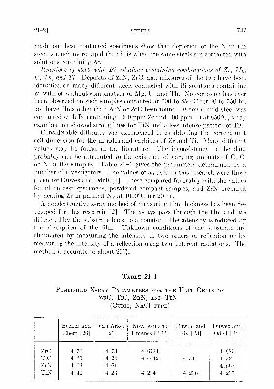
Considerable difficulty was experienced in establishing the correct unitcell dimension for the nitrides and carbides of Zr and Ti . Many differentvalues may be found in the literature . The inconsistency in the dataprobably can be attributed to the existence of varying amounts of C, 0,or N in the samples . Table 21-1 gives the parameters determined by anumber of investigators . The values of a 0 used in this research were thosegiven by Duwez and Odell [1] . These compared favorably with the valuesfound on test specimens, powdered compact samples, and ZrN preparedby heating Zr in purified N2 at 1000 °C for 20 hr .
A nondestructive x-ray method of measuring film thickness has been de-veloped for this research [2] . The x-rays pass through the film and arediffracted by the substrate back to a counter . The intensity is reduced bythe absorption of the film . Unknown conditions of the substrate areeliminated by measuring the intensity of two orders of reflection or bymeasuring the intensity of a reflection using two different radiations . Themethod is accurate to about 20%Jo .
PUBLISHED X-RAY
TABLE
PARAMETERS
21-1
FOR THE UNIT CELLS OFZRC, TIC, ZRN, AND TIN
(CUBIC, NAC1-TYPE
BeckerEbert
and[20]
Van Arkel[21]
KovalskiiUmanskii
and[22]
DawihlRix
and[23]
DuwezOdell
and[24]
zrC 4 .76 4 .73 4 .6734 4 .655TiC 4 .60 4 .26 4 .4442 4 .31 4 .32Zr\ 4 .63 4 .61 4 .567TiN 4 .40 4 .23 4 .234 4 .236 4.237
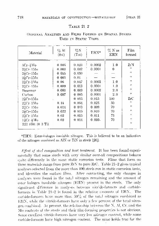
Effect of steel composition and heat treatment . It has been found experi-mentally that some steels with very similar over-all compositions behavequite differently in the same static corrosion tests . Films that form onthese materials range from pure ZrN to pure ZrC . Table 21-2 gives typicalanalyses selected from the more than 100 steels run in static corrosion tests,and identifies the surface films . After contacting, the only changes inanalyses were found in the total nitrogen remaining and the amount ofester halogen insoluble nitrogen (I'HIN) present in the steels . The onlysignificantt difference in analyses between nitride-formers and carbide-formers in Table 21--2 is found in the relative amounts of EHN. Thecarbide-formers have more than 50%jo of the total nitrogen combined asEll-N, while the nitride-formers have only a few percent of the total nitro-gen combined . At present, the relationship between the N, Al, Cr, and theMo contents of the steels and their film-forming properties is not obvious .Some excellent nitride-formers have very low nitrogen content, while somecarbide-formers have high nitrogen content . The same holds true for the
TABLE 21-2
ORIGINAL ANALYSES AND FILMS FORMED ON SPECIAL STEELSUSED IN STATIC TESTS
Material% Al(Sol)
%N(Tot) EHN* % N as
EHNFilm
formed
5Cr- 2'it1o24Cr-IMo24Cr-1Mo24Cr-IMo24Cr-1Mo24Cr-IMoBessemerCarbon24Cr-1Mo24Cr-1Mo24Cr-lMo24Cr-1Mo24Cr-1Mo11Cr-2MoRH 1081 (0 .3 Ti)
0 .0160 .0030 .0550 .0030 .060 .0090 .0030 .007
0 .440.0140.0220 .020.02
0 .0230 .0420 .0500 .010 .0470 .0130 .0090 .0050 .0150 .0540 .0130 .0150 .0150 .014
0 .00020 .0001
0 .00030 .00010 .00020 .00010 .0150 .0250 .0090 .0100 .0110 .010 .
1 .00
1 .01 .02 .02 .0
1005070707570
ZrN"""""""
ZrC""""""
*EHN : Ester-halogen insoluble nitrogen . This is believed to be an indicationof the nitrogen combined as AIN or TiN in steels [26] .

Al, Cr, and J-lo contents of the steels . The 1;IIN content of a steel can bereadily changed by short-time heat treatment at .700°C and higher [3], sothat this variable is controllable within limits .
To a first approximation, the corrosion resistance of a particular steel isenhanced by high "inhibitor" concentrations and,/ or the presence of in-soluble adherent films formed oil the steel surface . The first of these con-ditions is neither desirable nor practical in a solution-type fuel reactor be-cause of the adverse effect of Zr on the Li solubility . At present, work isbeing done to measure quantitatively the effects of different alloying con-stituents on the activities of N and C in steels . Consider the followingreactions :
Zr(Bi) + N(steel)
Zr- (film),
(21-1)
Zr(Bi) + ('(steel)
ZrC(film) .
(21-2)
Assuming that the films are insoluble ill Bi, then at equilibrium
K(ZrN) - (aZr)I(aN)'and
K(Zrc) = (azr) (ac)
(21-3)
If the products of the Zr activity in the Bi with the activities of the N andC in the steel are not sufficient to satisfy the respective equilibrium con-stants, the reactions will not occur, and the steel will not form ZrC orZrN films . If the activity products are greater than the constants, K(ZrC)or K(ZrN), the reactions will proceed until the activities are lowered to thesevalues. Thus, for a fixed Zr activity, the activities of N and C in the steeldetermine whether the carbide and nitride film-producing reactions shouldoccur. The excess of N or C above these equilibrium values should be ameasure of the driving force of reactions (21-1) and (21-2) to the right .
solution rate tests . The solution rates of Fe into Bi, and Bid- Zr and Mg,were measured in crucibles of a carbon steel, a 24% Cr-1% Mo, a 5%Cr-1 . 2 c-( Mo, and an AISI type-410 steel . The crucible, BI, and additiveswere equilibrated at 400 to 425 °C, the temperature rapidly raised to 600 °C,and the concentration of Fe in solution measured as a function of time .Results are shown in Fig. 21-2. In the presence of Zr +Mg, the 5%Cr-1 2"-( Mo and the AISI type-410 steels dissolved at approximatelythe same rate, while the 24% Cr-1% Mo steel dissolved more slowly . Nodetectable dissolution of Fe from the carbon steel was measured in 44 hrat 610°C. These results are parallel to the thermal convection loop results,and consistent with the film-formation studies in that the measured solu-tion rates are inversely proportional to the ability and rate at which thesteels form ZrN films. At present no data are available on rates of solutionfor ZrC-forming steels .
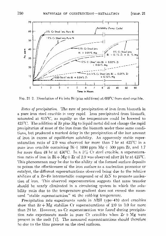
FIG. 21-2 . Dissolution of Fe into Bi (plus additives) at 600 °C from steel crucible .
Rates of precipitation . The rate of precipitation of iron from bismuth ina pure iron steel crucible is very rapid . Iron precipitated from bismuth,saturated at 615 °C, as rapidly as the temperature could be lowered to425°C. The addition of Zr plus Mg to liquid metal did not change the rapidprecipitation of most of the iron from the bismuth under these same condi-tions, but produced a marked delay in the precipitation of the last amountof iron in excess of equilibrium solubility. An apparently stable super-saturation ratio of 2 .0 was observed for more than 7 hr at 425 °C in apure iron crucible containing Bi + 1000 ppm Mg + 500 ppm Zr, and 1 .7for more than 48 hr at 450 °C . In a 5o Cr steel crucible, a supersatura-tion ratio of iron in Bi+Mg+Zr of 2 .9 was observed after 24 hr at 425 °C .This phenomenon may be due to the ability of the formed surface depositsto poison the effectiveness of the iron surface as a nucleation promotor orcatalyst, the different supersaturations observed being due to the relativeabilities of a Zr-Fe intermetallic compound or of ZrN to promote nuclea-tion of iron . This observed supersaturation suggests that mass transfershould be nearly eliminated in a circulating system in which the solu-bility ratio due to the temperature gradient does not exceed the meas-ured "stable supersaturation" at the cold-leg temperature .
Precipitation rate experiments made in AISI type-410 steel cruciblesshow that Zr + Mg stabilize Cr supersaturations of 2 .0 to 3 .0 for morethan 24 hr. However, no Cr supersaturation was found during precipita-tion rate experiments made in pure Cr crucibles when Zr + Mg werepresent in the melt [4] . The measured supersaturations should thereforebe due to the films present on the steel surfaces .
21-2.2 Corrosion testing on steels . The research effort on materials forcontainment of the LMFR has been concerned mainly with low-alloysteels having constituents which have low solubilities in Bi, such as C, Cr,and 11o. Although the solubilities of Fe and Cr are only 28 and 80 ppmrespectively at the intended maximum temperature of operation, severecorrosion and mass transfer are encountered when pure Bi or a U-Bi solu-tion is circulated through a temperature differential in a steel loop. Thisresults from the continuous solution of the pipe material in the hot portionof the system and subsequent precipitation from the supersaturated solu-tion in the colder portions . Zirconium additions to L-13i greatly reducethis corrosion and mass transfer .
The behavior of steels in U-Bi is studied in three types of tests . Thermalconvection loops are used to test materials under dynamic conditions . Inthese, the fuel solution is continuously circulated through a temperaturedifferential in a closed loop of pipe . Variables such as material composi-tion, maximum temperature, temperature differential, and additive con-centrations are studied in this test . More than sixty such loops have nowbeen run at BXL . The principal limitation in these tests is that the veloc-ities obtained by thermal pumping are extremely low when compared withthe I \IFR design conditions .
Forced circulation loops are used to study materials under environmentsmore closely approximating LMFR conditions. Three such loops are nowin operation at BNL and two more are under construction . A very largeloop (-1 in . ID) which will circulate t;-Bi at 360 U .S . gpm and transferihoiit 2 X 10`' watts of heat, is now under construction and is expected togo into operation late this year .
static tests, as discussed previously, in which steels are isothermally im-mer.i d in high-temperature F-Bi containing various additives, are usedto stredy their corrosion resistance and the inhibition process as a functionof additive concentration and steel composition . Most of the tests have1ceu performed on a 24%o Cr-I , itlo steel (Table 21-3) . However, sometests have also been made with higher Cr steels, 14% Cr-1/2% Mo,1 2` ; ('r-1 '2o'c Mo, and carbon steels .
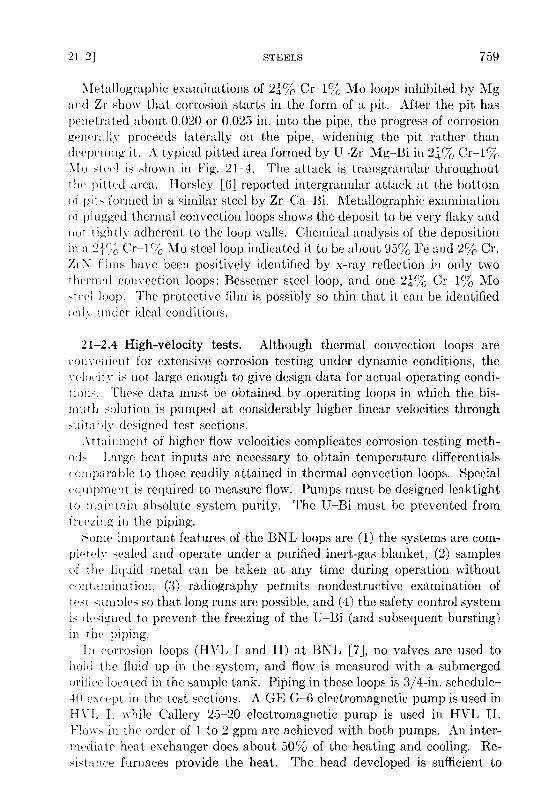
21-2.3 Thermal convection loop tests at BNL . A typical thermal con-vection loop that has been used at BXL is shown in Fig . 21-3. The loopis provided with a double-valve air lock at the top of the vertical sectionhick permits taking liquid metal samples while the loop is running without
contaminating the protective atmosphere . The hot leg is insulated andhe;it is supplied to that section of the loop while the cold leg is exposed andtwo small blowers are utilized to extract heat . The hottest point in theloop is at the "tee" at the upper end of the insulated section, and the coldestin the bottom of the exposed section . The total height of the loop proper is
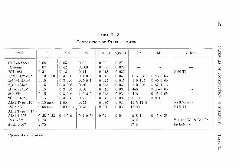
TABLE 21-3
COMPOSITION OF STEELS TESTED
Steel C Mn Si P(max) S(rnax) Cr Mo Others
Carbon SteelBessemerRH 10811/2Cr-1/2Mo*14Cr-1/2Mo*24Cr-lMo*5Cr-1/2Mo*5Cr-Si*9Cr-1Mo*AISI Type 410*18Cr-8NiAISI Type 304*AISI 4130*Rex AA*Stellite 90*
0 .080 .070 .310 .10-0 .200 .150 .150 .150 .150 .150 .15 max0 .08 max
0 .28-0 .330 .732 .75
0 .850 .420 .120 .3-0 .610 .3-0 .60 .3-0 .60 .3-0 .60 .3-0 .60 .3-0 .61 .002 .00 max
0 .4-0 .6
0 .010 .0090 .140 .1-0 .30 .5-0 .10 .500 .501 .0-2 .00 .25-1 .00 .750 .75
0 .2-0 .35
0.090 .0560 .0180 .0450.0450 .0450 .0450 .0450.0450 .0300 .030
0 .04
0 .270 .0220 .0200 .0450 .0450 .0300 .0300 .030 .030 .0300 .030
0 .04
-
0 .5--0 .811 .0-1 .51 .9-2 .64-64-68-10
11 .5-13 .518-20
0 .8-1 .14 .0
27 .0
0 .45-0 .660 .45-0 .660 .87-1 .130 .45-0 .650 .45-0 .650 .9-1 .1--
0 .15-0 .25
-0 30 Ti
Ni 0 .50 maxNi 8-11
V 1 .15 ; «" 18 Bal FeFe balance
*Nominal composition .
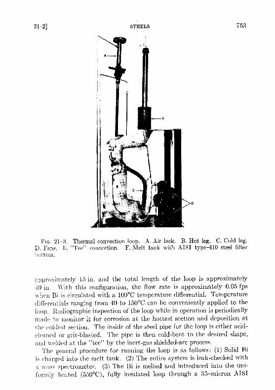
FIG . 21-3 . Thermal convection loop . A. Air lock. B. Hot leg. C. Cold leg .D. Fans. E. "Tee" connection . F. Melt tank with AISI type-410 steel filterbottom .
approximately 15 in . and the total length of the loop is approximately40 in . With this configuration, the flow rate is approximately 0 .05 fps
when BI is circulated with a 100 °C temperature differential. Temperature
differentials ranging from 40 to 150 °C can be conveniently applied to the
loop. Radiographic inspection of the loop while in operation is periodicallymade to monitor it for corrosion at the hottest section and deposition atthe coldest section . The inside of the steel pipe for the loop is either acid-cleaned or grit-blasted . The pipe is then cold-bent to the desired shape,and welded at the "tee" by the inert-gas shielded-arc process .
The general procedure for running the loop is as follows : (1) Solid Bi
is charged into the melt tank . (2) The entire system is leak-checked witha mass spectrometer . (3) The Bi is melted and introduced into the uni-formly heated (550 °C), fully insulated loop through a 35-micron AISI
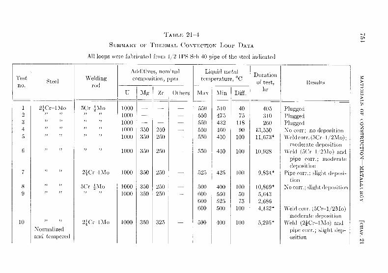
TABLE 21-4
SUMMARY OF THERMAL CONVECTION Loop DATA
All loops were fabricated from 1/2 IPS Sch 40 pipe of the steel indicated
Testno .
Steel Weldingrod
Additives, nominalcomposition, ppm
Liquid metaltemperature, °C
Durationof test,
hrResults
U Mg Zr Others 1V'Iax Min Diff .
1 24Cr-1Mo 5Cr2Mo 1000 - - 550 510 40 405 Plugged2 1000 550 475 75 310 Plugged3 1000 550 432 118 260 Plugged4 1000 350 250 550 460 90 13,550 No corr ; no deposition5 1000 350 250 - 550 450 100 11,673* Weld corr . (5Cr-1/2Mo) ;
moderate deposition6 1000 350 250 550 450 100 10,928 Weld (5Cr-1/2Mo) and
pipe corr . ; moderatedeposition
7 24Cr-l'o 1000 350 250 525 425 100 9,834* Pipe corr . ; slight deposi-tion
8 5Cr2TIo 1000 350 250 500 400 100 10,869* No corr . ; slight deposition9 1000 350 250 600 550 50 5,643
600 525 75 2,686600 500 100 4,152* Weld corr . (5Cr-1/2Mo)
moderate deposition10 24Cr-lMo 1000 350 325 500 400 100 5,295* Weld (21 0-1Mo) and
Normalized pipe corr . ; slight dep-and tempered osition

II
12
13
14
15
16
1718
19202122
23
24
;('r I\lolb In (rt2 . ;('r IMOgraphite insert2 ;Cr 1\l0
240 - -1\Io
2'('i-1\Ionitrided afterwelding210-1Mo
24Cr-1\IoBessemerCarbon steelR111081
2'Cr-zllo14Cr-zJIo14Crz\Io
5Cr-Si
9Cr-1Mo
? . ;('r ~[
i('r .',A10
Carbon steel
RH108114C 1
21014Cr-2Mo14Cr-2Mo
5CrzMo
9Cr-11\1o
1000
1000
1000
1000
1000
1000
10001000
1000100010001000
1000
1000
3511
350
350
350
350
350
350350
350350350350
350
350
i
:350
250
250
250
250
250250
250325400325
250
250
-
500
550
550
525
550
550
650550
450500525500550550
550
400
440
440
400
425
420
500415
415405425400440420
400
100
110
110
125
125
130
150135
13595
100100100130
150
1,631*
15,086
16,906
10,649*
10,425*
5,323
1,18012,356
8,231*8,538*9,194*963
6,240*3,340
6,025
No corr . ; slight deposi-tion
Severe corr . ; moderatedeposition
Corroded through atweld (50-1/2Mo) ;moderate deposition
`\eldcorr.(5Cr-1/2Mo) ;moderate deposition
No corr . ; slight deposi-tion
Heavy pipe corr . ; heavydeposition
Plugged; severe corrosionNo corr . ; no deposition
No corr . ; no depositionNo corr . ; no depositionNo corr . ; slight deposition
No corr . ; slight depositionSlight corr . ; some depo-
sitionSevere corr . ; very heavy
deposition
*Test in progress as of 3/15/58 . Time indicated is duration at temperature differential . Results indicated for these loops arebased on radiographic inspection .
continued
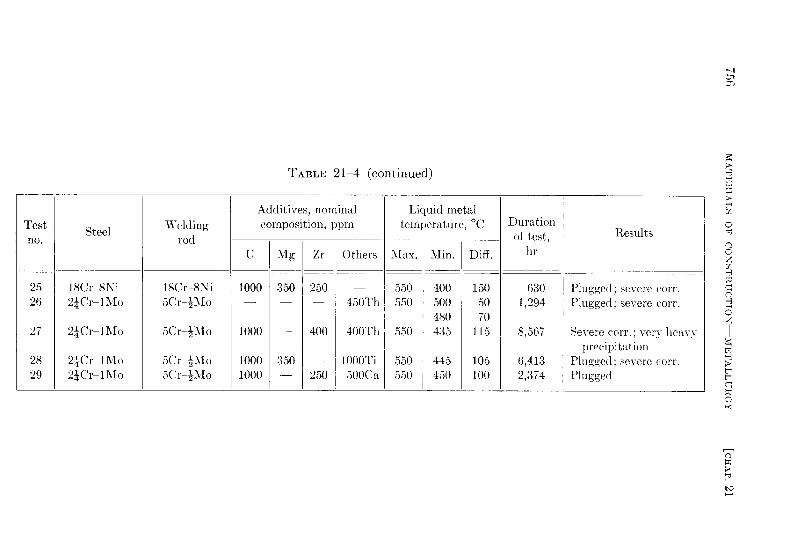
TABLE 21-4 (continued)
Test WeldingAdditives, nominalcomposition, ppm
Liquid metaltemperature, °C Duration
no .Steel
rod of test, Results
U Mg Zr Others Max . Min . Diff . hr
25 18Cr-8Ni l8Cr-8Ni 1000 350 250 550 400 150 630 Plugged ; severe corr .26 24Cr-lMo 5Crz \1o - 450Th 550 500- 50- 1,294 Plugged; severe corr .
480 7027 24Cr-1Mo 5Cr-zMo 1000 - 400 400Th 550 435 115 8,567 Severe corr . ; very heavy
28 24Cr-11\Io 5Cr2Mo 1000 350 - 1000Ti 550 445 105 6,413
prec ipi tation
Plugged ; severe corr .29 24Cr-11M oMo 5Cr zl\1o 1000 - 250 500Ca 550 450 100 2,374 Plugged

type-410 stainless-steel filter. (4) Zr and Mg are introduced into the loopthrough the air lock. (5) The Bi in the loop is sampled, using a graphitesample extractor, to check for additive concentration . (6) Uranium isadded if additive concentrations are as desired ; if necessary, additiveconcentrations are adjusted prior to U addition . (7) The temperature dif-ferential is obtained by removing the insulation from the cold leg andstarting the fans. The temperature differential is usually applied in twosteps, first 40°C and then the differential at which the loop is to operate .(8) The entire loop is radiographed every 750 hr . (9) The liquid metal issampled at regular intervals . (10) After completion of the test the entireloop is sectioned longitudinally and transversely for metallographic ex-amination .In Table 21-4, data from 29 thermal convection loop experiments at
BNL are summarized . The first three loops were fabricated from 24%Cr-1% Mo steel pipe and the U-Bi solution was not inhibited . Loops No. 4to 17 inclusive were made with 24% Cr-1% Mo steel and inhibited withMg and Zr . Loops No. 18 to 25 inclusive were fabricated from varioustypes of steels, ranging from Bessemer to 1870 Cr-8°%0 Ni austenitic steels .Loops No. 26 to 29 were made from 24/0 Cr-1% Mo steel pipe . The pur-pose of these tests was to study the effectiveness of Ca, Th, and Ti as in-hibitors .
It can be seen from the first three tests that deposition in the cold legs ofuninhibited loops after a few hundred hours is sufficient to stop flow . Thesetests show conclusively that uninhibited U-Bi solution causes serious masstransfer of this steel even at a temperature differential as low as 40 °C .Metallographic examination of the hot legs of these loops showed a gen-eralized intergranular attack .
The data from loops inhibited with 350 ppm of Mg and 250 to 350 ppmZr (loops No . 4 to 17) show that mass-transfer rate can be decreased con-siderably by the introduction of these additives . This effect is attributedto the formation of a ZrN film on the steel surface [4,5] . The data demon-strate, however, that this film is not completely protective in 24° 0 Cr-1°%0Mo steel system. Test No . 4 indicates that for a differential in the order of
90°C, the film was sufficiently protective to prevent corrosion or depositionin 1:3,550 hr of test. For temperature differentials of 100°C or higher, in-cipient corrosion can be expected in about 5000 to 6000 hr . Some of the210-1 Mo loop sections were joined with 5 Cr-1/2 Mo welding rod . Thishigher chromium material has lower resistance to inhibited U-Bi than thepipe, so that corrosion generally starts at these welds . Increasing thetemperature of the hot leg seems to increase the rate of corrosion, as il-lustrated by the results of loops No . 5 to 9 inclusive, which were all testedat 100°C temperature differential .

Loop No. 10, which was normalized from 954°C and tempered at 732 °Cafter welding, stood up poorly when compared with other tests . The heat-treating was done in an argon atmosphere, and no subsequent alterationwas made to the surface left by the heat treatment . This heat treatmentwas thought, from some observations in the pumped loops, to improve cor-rosion resistance . It is believed that the poor results of test No . 10 are dueto alteration of the surface during the heat treatment and not to themetallurgical structure of the steel . Loops No. 11 and 12 had Be and graph-ite inserts in the hot leg to study their effect on mass transfer and also thestability of U, Mg, and Zr concentrations . No detrimental effects on eitherhave been observed .Loop No. 15, made of a 24 Cr-I 1\1o steel that was internally nitrided to
a depth of 0 .015 inch, appears to be standing up much better than other24 Cr-1 Mo loops tested at a 125°C temperature differential . The addednitrogen in the steel probably promoted the formation of the ZrN film . Aslight loss in Zr has been observed in this test, but other additive concen-trations have remained constant .
Results of tests No . 18 to 25 show that higher-alloyed steels are inferiorto the carbon steels in inhibited U-Bi . Loop No . 18, fabricated fromBessemer carbon steel, showed exceptional resistance to U-Bi . Metal-lographic examination of this loop indicated no evidence of corrosion ordeposition after 12,356 hr of operation at 135 °C temperature differential .X-ray diffraction studies of a polished insert in this loop indicated that aZrN film was present ; however, no film was detected on the pipe surface .Considerable evidence of structural instability in the form of grain coarsen-ing and graphitization of the Bessemer steel was found in the metal-lographic examination of the loop . A medium carbon steel containing Ti,Rh-1081, also exhibited good resistance to U-Bi corrosion . The lowerchromium steels, such as 1/27c Cr-1/270 Mo and 14% Cr-1/2% Mo(tests No. 20, 21, and 22), also seem to be standing up well to inhibitedU-Bi. The testing of these steels will be increased .Loops No. 26 to 29 were run to study the effectiveness of Th, Th + Zr,
Ti + Mg, and Ca + Zr as inhibitors . It can be seen from these tests thatthese inhibitors were much inferior to Mg and Zr combinations . In testsNo. 27 and 29 it was found that a slow but continuous loss of Zr, Th, andCa occurred . Horsley [6] also ran Bi loops containing Ca and Zr as in-hibitors . He reported similarly that the loops plugged, and that Ca and Zrwere lost from the melt . The results of loop No. 28 indicate that Mg andTi provide some inhibition, but are not nearly as effective as Mg and Zr .Metallographic examination of this loop shows that the corrosion was uni-form and that most of the attack took place 4 to 6 in . downstream from the"tee," in an area which is normally somewhat lower in temperature thanthe "tee ."
Metallographic examinations of 24% Cr-1% Mo loops inhibited by Mgand Zr show that corrosion starts in the form of a pit . After the pit haspenetrated about 0 .020 or 0.025 in . into the pipe, the progress of corrosiongenerally proceeds laterally on the pipe, widening the pit rather thandeepening it . A typical pitted area formed by U-Zr-Mg-Bi in 24% Cr-1%Mlo steel is shown in Fig . 21-4. The attack is transgranular throughoutthe pitted area . Ilorsley [6] reported intergranular attack at the bottomof pits formed in a similar steel by Zr-Ca-Bi. Metallographic examinationof plugged thermal convection loops shows the deposit to be very flaky andnot tightly adherent to the loop walls . Chemical analysis of the depositionin a 24 o Cr-1% Mo steel loop indicated it to be about 951/0 Fe and 270 Cr .ZrA films have been positively identified by x-ray reflection in only twothermal convection loops : Bessemer steel loop, and one 24% Cr-1% Mosteel loop . The protective film is possibly so thin that it can be identifiedonly under ideal conditions .
21-2 .4 High-velocity tests . Although thermal convection loops arecom-enient for extensive corrosion testing under dynamic conditions, thevelocity is not large enough to give design data for actual operating condi-tion. These data must be obtained by operating loops in which the bis-rmuth solution is pumped at considerably higher linear velocities throughsuitahly designed test sections .
Attainment of higher flow velocities complicates corrosion testing meth-od. Large heat inputs are necessary to obtain temperature differentialseoniparable to those readily attained in thermal convection loops . Specialequipment is required to measure flow . Pumps must be designed leaktightto maintain absolute system purity . The U-Bi must be prevented fromfreezing ill the piping .Some important features of the BNL loops are (1) the systems are com-
pletely sealed and operate under a purified inert-gas blanket, (2) samplesof the liquid metal can be taken at any time during operation withoutcontamination, (3) radiography permits nondestructive examination oftest samples so that long runs are possible, and (4) the safety control systemis lesigued to prevent the freezing of the U-Bi (and subsequent bursting)in the piping .
Iii corrosion loops (HVL I and II) at BNL [7], no valves are used tohold the fluid up in the system, and flow is measured with a submergedorifice located in the sample tank . Piping in these loops is 3/4-in . schedule-4O except in the test sections . A GE G-6 electromagnetic pump is used inHVL I. while Callery 25-20 electromagnetic pump is used in HVL II .Flows in the order of 1 to 2 gpm are achieved with both pumps . An inter-mediate heat exchanger does about 50% of the heating and cooling . Re-sistance furnaces provide the heat . The head developed is sufficient to

FIG . 21-4 . Pitted area at "tee" in Loop #12 . (a) Macrograph. (b) Micrograph(original 250X) of pitted areas .

FIG. 21-5 . High-velocity pump test loop .
allow the use of short small-diameter test sections in which velocities up to8 fps are attained .
A third corrosion loop (loop G) uses a canned centrifugal pump to cir-culate the U-Bi, permitting flows up to 4 .8 gpm and velocities up to 14 fpsto be attained . Engineering devices such as bellows-sealed valves andpressure transmitters are being tested in this loop, as well as materials forhigh-velocity corrosion resistance . Heating and cooling is the same as inHVL I and II. The loop is fabricated for the most part of 24% Cr-1% Mosteel . 1-in . schedule-40 piping .
Two more loops (HVL III and IV), similar to loop G, are now underconstruction . These are shown in Fig . 21-5. Flow rates up to 12 gpm,velocities up to 25 fps, and temperature differentials of 150°C will beattainable in these loops. HVL III will be fabricated of 24% Cr-1% Mosteel. while HVL IV will be of 14% Cr-1/2% Mo steel .
While the basic material of construction of these loops is a Cr-Mo steel,test scctlons are usually made up of a variety of steels and weldments .All welds are made by the inert arc process. Cleaning, for the most part,is done by grit-blasting .

TABLE 21-5
RESULTS FROM HIGH VELOCITY Loops
Loop no . Material*
Temp. (Bulk), Temp. Film, Additive cone . Time
testhr
Flow, Remarks
Max Min Max Min Mg Zr U
HVL I:Run 1Run 2
Run 3Run 4
Run 5
HVL II :Run 1
Loop G :Run 1Run 2
24Cr-1Mo24Cr-lMo
24Cr-1Mo24Cr-1Mo
14Cr-zMo(loop refabri-cated)
24Cr-1Mo
24Cr-1Mo
24Cr-1Mo
520520
520544
520
520
525
525
414414
414417
445
445
473
450
525525
525550
525
522
529
526
400400
400400
428
427
458
435
350350
350350
350
350
350
350
300350
300250
250
350
350
250
9201000
10001000
1000
1000
1000
900
10261026
10062591
40001
74001
938
2500t
1 .201 .20
1 .251 .1
4.0
4 .8
No corrosionCavitation pits in high veloc-
ity test sectionNo cavitationSevere pits and mass transfer ;
loop sectionedNo corrosion; some transfer
after 4000 hr
Slight pit corr . i n welds ; trans-fer detected after 2500 hrat AT; loop still in opera-tion 7000 hr
Pt . corr . of 4-6 Cr-11\1o welds ;corr. of AISI 410 SS .
No corr. after 2500 hr
*This is the major material of construction . The actual test section is a composite of many materials .tStill in operation . Test time as of 3/15/58 .
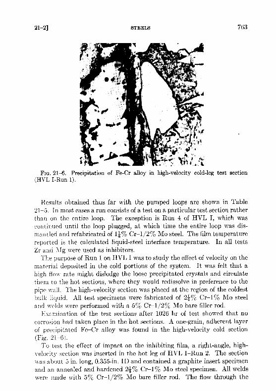
FIG. 21-6 . Precipitation of Fe-Cr alloy in high-velocity cold-leg test section(HVL I-Run 1) .
Results obtained thus far with the pumped loops are shown in Table21-5. In most cases a run consists of a test on a particular test section ratherthan on the entire loop . The exception is Run 4 of HVL I, which wascontinued until the loop plugged, at which time the entire loop was dis-mantled and refabricated of 1*% Cr-1/2% Mo steel. The film temperaturereported is the calculated liquid-steel interface temperature . In all testsZr and Mg were used as inhibitors .
The purpose of Run 1 on HVL I was to study the effect of velocity on thematerial deposited in the cold portions of the system . It was felt that ahigh flow rate might dislodge the loose precipitated crystals and circulatethem to the hot sections, where they would redissolve in preference to thepipe wall . The high-velocity section was placed at the region of the coldestbulk liquid . All test specimens were fabricated of 24% Cr-1% Mo steeland welds were performed with a 5% Cr-1/2% Mo bare filler rod .
Examination of the test sections after 1026 hr of test showed that nocorrosion had taken place in the hot sections . A one-grain, adherent layerof precipitated Fe-Cr alloy was found in the high-velocity cold section(Fig. 21-6) .
To test the effect of impact on the inhibiting film, a right-angle, high-velocity section was inserted in the hot leg of HVL I-Run 2 . The sectionwas about 5 in . long, 0.355-in . ID and contained a graphite insert specimenand an annealed and hardened 24% Cr-1% Mo steel specimen . All weldswere made with 5% Cr-1/2% Mo bare filler rod . The flow through the
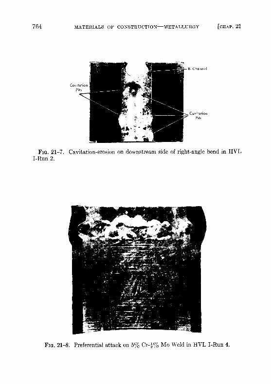
FIG. 21-7 . Cavitation-erosion on downstream side of right-angle bend in HVLI-Run 2 .
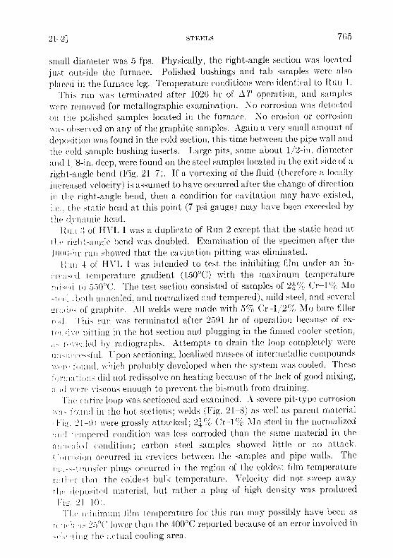
FIG . 21-8. Preferential attack on 5% Cr-2% Mo Weld in HVL I-Run 4 .
small diameter was 5 fps . Physically, the right-angle section was locatedjust outside the furnace . Polished bushings and tab samples were alsoplaced iii the furnace leg . Temperature conditions were identical to Run 1 .
This run was terminated after 1026 hr of AT operation, and sampleswere removed for metallographic examination . 1 o corrosion was detectedon the polished samples located in the furnace . No erosion or corrosion%N - as observed on any of the graphite samples . Again a very small amount ofdeposition was found in the cold section, this time between the pipe wall andthe cold sample bushing inserts . Large pits, some about 1/2-in . diameterand 1,S-in . deep, were found on the steel samples located in the exit side of aright-angle bend (Fig . 21-7) . If a vortexing of the fluid (therefore a locallyincreased velocity) is assumed to have occurred after the change of directionin the right-angle bend, then a condition for cavitation may have existed,i .e ., the static head at this point (7 psi gauge) may have been exceeded bythe dynamic head .Rim :1 of HVL I was a duplicate of Run 2 except that the static head at
the right-angle bend was doubled . Examination of the specimen after the1000-hr run showed that the cavitation pitting was eliminated .
l ;un 4 of HVL I was intended to test the inhibiting film under an in-reaped temperature gradient (150 °C) with the maximum temperature
r:ii<<'d to 550 °C. The test section consisted of samples of 2~2"76 Cr-l'/(, Mol both annealed, and normalized and tempered), mild steel, and several
`r:ules of graphite . All welds were made with 5% Cr-1/2'/'O Mo bare fillerraid . This run was terminated after 2591 hr of operation because of ex-
pitting in the hot section and plugging in the finned cooler section,rf~vve :iled by radiographs . Attempts to drain the loop completely were
ui u i e ful. Upon sectioning, localized masses of intermetallic compounds«- .r(, fund, which probably developed when the system was cooled . These1 ruiations did not redissolve on heating because of the lack of good mixing,ai,d were viscous enough to prevent the bismuth from draining .
The entire loop was sectioned and examined . A severe pit-type corrosiona found in the hot sections ; welds (Fig . 21-8) as well as parent material
21-91 were grossly attacked ; 24%, Cr-1% Mo steel in the normalized: :11(1 capered condition was less corroded than the same material in theaiiiwcled condition ; carbon steel samples showed little or no attack .Cnrrn>ion occurred in crevices between the samples and pipe walls . Them : :- t ansfer plugs occurred in the region of the coldest film temperaturerct hi r than the coldest bulk temperature . Velocity did not sweep awayrlii deposited material, but rather a plug of high density was producedVia. 21-10i .The minimum film temperature for this run may possibly have been as
iici , li : i s 25 °C lower than the 400 °C reported because of an error involved inle tin the actual cooling area .
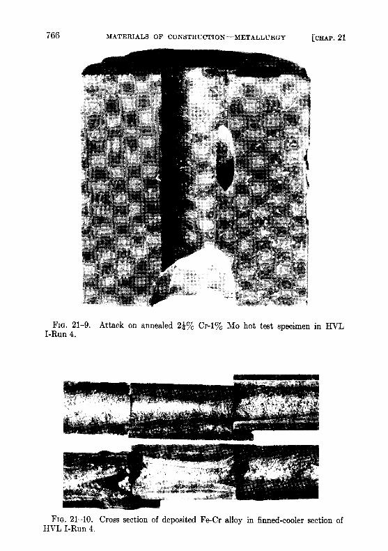
FIG . 21-9 . Attack on annealed 21%o Cr-1% Mo hot test specimen in HVLI-Run 4 .
FIG. 21-10 . Cross section of deposited Fe-Cr alloy in finned-cooler section ofHVL I-Run 4 .
Loop C-Run 1, had a hot-leg test section consisting of specimens of2'c70 Cr-1~' Mo, 14% Cr-1 /2 170 Mo, AISI type-410, and Bessemer steels,joined with welds made with 24c70 Cr-1c70 Mo, I% Cr-1/2c70 Mo, 5%Cr-1 ; 2(,`o Mo, AISI type-410, and mild steel bare filler rods . This run wasterminated after 938 hr of operation at a 75 °C film gradient and a flow of 4fps in the test section. Examination of the test section showed that weldsmade with a 5070 Cr-1/2 (70 Mo rod were severely attacked, while thosemade with a 2',°70 Cr-1% Mo rod and a 14 (70 Cr-1/2%e Mo rod were notattacked. The only other corrosion observed in this run was some slightattack on welds and base material of AISI type-410 steel . Cavitation pitswere also observed on the pump impeller .
Loop C-Run 2, 1IVL I-Run 5, and HVL II-Run 1 are still under test .In these loops are specimens of 24% Cr-1°70 Mo and 14070 Cr-1/2°70 Mosteels having various heat treatments, AIST type-410 and Bessemer steels,and welds made with 14070 Cr-1/2°70 Mo, 2,'070 Cr-1% Mo, 5%0 Cr-1/2%JIo, AISI type-410 and mild steel bare filler rods . No corrosion has beendetected radiographically in the loop C test section after 2500 hr of opera-tion . No corrosion has been detected in the HVL I-Run 5 test section ;however, slight deposition has been detected in the finned cooler . Thisprecipitate was first observed after 1400 hr of operation but is still not seri-ous after 4000 hr .
Pitting of welds made with 5% Cr-1/2% Mo rod and possible corrosionof a 2 -1'- Cr-1(70 Mo weld have been detected in Run 1 of HVL II . Thisloop first operated 2500 hr with a film AT of 75 °C (500 to 425 °C film) withno radiographically detectable corrosion and little or no mass transfer .The temperature differential was then increased to 75 °C bulk (522 to427°(' film) . After 100 hr at this new differential, deposition in the coolerwas observed . Pitting of the 5(70 Cr-1/2(70 Mo weld was detected after2000 hr at the new differential. However, after a total of 7400 hr of tem-perature gradient operation, the amount of pitting and transferred ma-terial was not serious enough to stop loop operation .
The effect of velocity on corrosion and mass transfer is not apparent atthis time. This is mainly due to a lack of tests in which velocity is the onlyvariable . Correlation between the pump loops and thermal convectionloops suggests that velocity has little effect on mass transfer other than onthe type of plug formed, provided conditions for cavitation do not exist .However, results from tests now under way should definitely evaluate thisvariable .
21-2.5 Rapid oxidation of 24°70 Cr-1°/0 Mo steel . In a pumped Bi loopcontaining Mg+Zr, the 24% Cr-1% Mo steel adjacent to a pinhole leak wasfound to be severely oxidized . The appearance of the oxide scale was verysimilar to that reported by Leslie and Fontana [8] . These investigators
found that rapid oxidation of a 16% Cr-25% Ni-6% Mo steel will occur in astagnant atmosphere, and that MoO3 catalyzed the rapid oxidation of thissteel. They also reported that Bi203 could produce a similar effect .
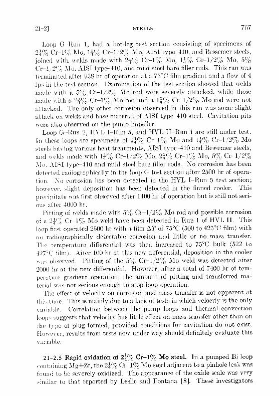
A test simulating a leak in a loop was made to study this phenomenon .A 2 11% Cr-1% Mo steel pipe was filled with Bi containing 1000 ppm U,350 ppm Mg, and 250 ppm Zr . A 1/32-in. hole was drilled in the pipe belowthe Bi level. A patch of asbestos tape 2 in . in diameter was put over thehole . The tube was then heated to 594°C and pressurized to 5 psi to forceout a small amount of Bi . The pressure was dropped as soon as some Bi hadleaked out and the tube was then heated at 594 °C for 1025 hr. The appear-ance of the pipe underneath the asbestos tape patch and a cross section ofthe oxidized area are shown in Fig . 21-11. A complete oxidation throughthe pipe wall has occurred in the area adjacent to the leak .
Tests run at 738 and 816°C in covered crucibles show that chemicallypure Bi203 can promote rapid oxidation in 24% Cr-1% Mo, 14% Cr-1/2/0Mo, and carbon steels . Tube tests and crucible tests are being continued todetermine the minimum temperature at which rapid oxidation is a problem .
21-2 .6 Radiation effects on steels . Since steel will be in direct contactwith the liquid U-Bi fuel, it is important to determine the effects of fissionrecoils and fast neutrons on the rate of corrosion or erosion . If corrosioninhibition is achieved by a layer of ZrN between the Bi and the steel, thereis concern that fission recoil particles might destroy this film . Local heating,resulting from the stopping of the particles, may cause a differentialexpansion between the layer and the steel . Consequently, the layer maybreak away from the steel, leaving the surface exposed to BI attack. Onthe other hand, neutrons should not he detrimental to a thin ZrN layer,pe• se .
Effects of neutrons must also be determined on the mechanical propertiesof the steels at reactor temperatures. radiation-induced increases in tensilestrength and elastic modulus may not anneal out at LMFI- operatingtemperatures . A decrease in the impact strength is not considered tooprobable at these temperatures, although the possibility must beinvestigated .
l'o study the radiation effects on materials, a capsule test has been de-veloped . The capsules, in « - hick samples are inserted in a highly enrichedV--B] solution containing Mg and Zr inhibitors, are exposed in the BNLreactor awl irradiated to the desired level. The test has the advantage ofattaining high temperatures (700 ° (') and aa high fission recoil density .
Samples of l ( c Cr-1 2%Mo acid 2 ;% 01% JIo have been placed inone of these capsules with Bi containing -1000 pprn U, 2500 ppm Zr, and3500 ppm Mg . The exposure was approximately 2 .2 X I VI nvt . Sectioningof this capsule has shown no corrosion of the samples . A second capsule
FIG . 21-11 . Rapid oxidation of 21% G-1% Mo steel pipe after 1025 hr at 594°Cat pinhole leak .
has been put in the BNL pile containing samples of 14% Cr-1/2% Mo andmild steels . Results are not yet available .
Dynamic tests of the reaction between Bi and steel in the presence of aradiation field must be completed before a final selection can be made ofmaterials for the LMFR . The effect of velocity on corrosion is not certainfrom the out-of-pile studies, so that no exact analogy can be made betweenout-of-pile forced circulation loops and in-pile capsules . There has beenlimited work done at Harwell [6] with thermal convection loops in and outof a radiation field . These loops had no U but did contain Ca and Zrinhibitors . The data suggest that pile radiation may have induced someacceleration of mass transfer .

An in-pile, forced-circulation loop has been built at BNL and two othersat Babcock & Wilcox Research Laboratory to test the corrosion stabilityof LMFR materials under conditions to be expected in the reactor experi-ment . In this loop, BI containing approximately 1500 ppm of U 235 , 180 ppmZr, and 350 ppm Mg will be pumped at a rate of 5 to 7 gpm . The bulk01' will be approximately 75°C, with a maximum temperature of 500 °C .There are three sample sections in the loop : one, containing samples of14% Cr-1/2% A~Mo steel, 2 1,% Cr-i% Mo steel, Be, and graphite, will be atthe center of the reactor and will be in a flux of approximately 3 X 10 73thermal neutrons ; one within the shield will see delayed neutrons at atemperature of 500 °C ; and the third section will be outside the reactor at atemperature of 425 °C. This test is presently being assembled, and will beoperating late in 1958 .
21-3 . NONFERROUS METALS
Several nonferrous metals are receiving attention as container materials,principally because of their low solubility in bismuth . At this time only asmall amount of work has been done on testing these metals . The followingis a brief discussion of some of the most important of them .
21-3.1 Beryllium . In the Liquid Metals Handbook, beryllium has beenreported to have a good resistance to attack by liquid bismuth at 500 °Cand probably also at 1000°C. Recent work at Harwell has shown thatberyllium has good resistance to mass transfer by liquid bismuth circulatingthrough a temperature gradient of 500 °C, with a base temperature of300°C. Recent advances in the production technology of beryllium metalhave improved its mechanical properties sufficiently so that it is now pos-sible to consider this metal for reactor core vessel or moderator . However,no data on reaction between beryllium and uranium additives and fissionproducts dissolved in a liquid metal fuel are available . Since uranium isknown to form a stable intermetallic compound with beryllium, the possi-bility of such a reaction must be investigated before beryllium can berecommended as a moderator in contact with a liquid-metal fuel. Statictests on the resistance of Be to attack by U-Bi at 550 and 650 °C showedsome (but not conclusive) evidence of a slight attack (less than 1 mil/yraverage penetration) . A slight attack on Be was noted by Brasunas by a2% U-Bi alloy after 4 hr at 1000 °C .
21-3 .2 Tantalum. Recent work at the Ames Laboratory indicates thattantalum is an excellent material to contain U-Bi . A 5 w/o U in Bi solutionwas circulated through a 3/4-in . OD by 0 .030-in. wall tantalum loop at arate of 800 lb/min . The U-Bi was circulated with an electromagnetic pumpand the temperature differential was 100 °C (950 to 850 °C) .

Liquid metal samples taken during operation showed that the Ta con-centration never exceeded 6 ppm . After 5250 hr of operation, the loop wasshut down and examined metallographically . -No transferred material wasdetected in the cold leg and the corrosion was less than 1 mil . The tantalumremained shiny and ductile throughout the experiment .
liven though the above results are hopeful, the use of tantalum as acontainer material for a U-Bi reactor system is limited by (1) its poor airoxidation resistance, (2) difficulty of fabrication, (3) cost .
21-3 .3 Molybdenum . Molybdenum is also known to be highly resistantto U-Bi. However, its use as a container material is hampered by its pooroxidation resistance and difficult fabrication .Some success has been obtained, however, with Mo applied as a coating
on low-chrome steel. The process was developed by the Vitro Corporationand is described in detail in KLX-10009 . Essentially, the coating is appliedby first electrophoretically depositing 807 Mo + 20% MoO3 on the steel .The coating is then pressed, reduced in a H2 atmosphere, repressed andsintered in an H z + HCl atmosphere .
These specimens have been subjected to static Bi which was temperaturecycled at 550 to 400 °C. Filtered liquid metal samples of the Ri were takenand analyzed for the presence of Fe and Cr . The Bi was allowed to stay atthe 550°C temperature overnight before a liquid metal sample was taken .After 4300 hr at temperature and some 17,000 cycles, the concentrationof Fe was 6.9 ppm and Cr 2 ppm . By comparison, the solubilities of Feand Cr at 550 °C were 30 ppm and 80 ppm respectively .
On the basis of their low solubility in U-Bi such materials as tungsten,tantalum, molybdenum, and beryllium could be classified as containermaterials . Their practical use, however, is governed by their poor airoxidation resistance, fabrication difficulties, availability, and cost .
21-4 . BEARING MATERIALS
The relative bearing properties of materials for use as valve seats, disks,and guides are being determined in Bi containing Mg and Zr . Testing isdone under a boundary lubrication condition .
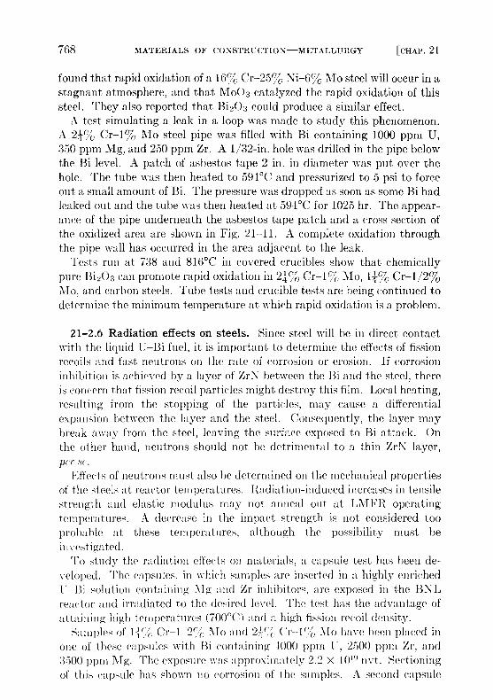
The test apparatus consists of a main test chamber and a sump tank tofacilitate easy handling of the liquid Bi and to permit periodic sampling ofthe liquid metal . The main test chamber, containing the samples and thesample loading mechanism, is shown in the cutaway of Fig . 21-12. Themethod of transmitting the load with air pistons through flexible bellowscan he clearly seen . A second chamber mounted on top of the main testchamber contains a Dc Thymotrol motor which rotates the cylindricalspecimen . The power input versus torque characteristics of the motor when
FIG. 21-12 . Bearing materials test apparatus .
operated in a helium atmosphere using "high-altitude" aircraft brusheshas been determined .
A test consists of contacting the rotating cylindrical specimen with aflat specimen under a constant force for a set period of time under set condi-tions . After the contact run, the Bi is removed from the specimen . Thedegree and kind of scoring, galling, material transfer, and depth of wear onthe surface were noted . Surface roughness measurements are made with aprofilometer . Hardness measurements are made . Coefficients of frictionare calculated from the measured torque data by the equation
f Pr ,
(21-4)
where f = the coefficient of friction, I' = the applied load (lb), r = theradius of sleeve (ft), and T = the torque (ft-lb) .
In general, the hard-to-hard material combinations have shown goodwear resistance except for some scoring . The best hard material testedthus far is A1 203 flame-coated on AISI 4130 steel. When this material wascontacted against itself, no wear or scoring could be detected . This ma-
terial will be thermally cycled and exposed to inhibited L-Bi for long timesto evaluate its utility . Stellite 90 and Rex AA also behaved well. Contactsmade with common die steels and low-alloy steels have exhibited severescoring and wear . Corrosion has also been detected on these samples . Ofthe cemented carbides, only TIC with either a mild steel or 2-, % Cr-1 170 1\1obinder has been tested . This material did not show good wear propertiesand also exhibited some pitting corrosion .
Graphitar versus tool steel and Mo versus Rex AA or Stellite 90 haveshown the best results of the hard versus soft combinations tested . Theresults have been good in that the wear has been very smooth ; however,the wear has been excessive . The use of these combinations would be limitedto very low-load applications .
21-5 . SALT CORROSION
In earlier chapters, it was pointed out that one of the chief advantagesof the LMFR lies in the possibility of easy chemical processing. Severalprocessing techniques have been studied, most of which are based onpyrometallurgical processes. The two chief pyrometallurgical methodsunder consideration are the chloride process, in which the bismuth fuel iscontacted with a ternary mixture of molten chloride salts, and the fluorideprocess, in which the bismuth fuel is contacted with molten fluoride saltscontaining hydrogen fluoride . As may be imagined, the constructionmaterial problem for these plants is very difficult .
A corrosion test program is actively under way at BNL and ArgonneNational Laboratory on the chloride and fluoride processes respectively .At BNL, these tests have consisted principally of rocking furnace and tabexposure tests .
In the rocking furnace test, a piece of tubing approximately 12 in . longand 1 2 in . I1), containing a charge of either salt or a mixture of salt andbismuth, is placed on a rocking rack in a furnace . This rack alternatelytilts to one end for a period of 1 min and then to the other end for a likeamount of time. The two ends of the furnace are kept at 450 and 500 °Cin order to give a temperature differential and thus induce mass-transfercorrosion . The standard test period has been 1000 hr . These tests are partof the initial screening program . When they are completed, the metalswhich have given the best performance will be further evaluated in testloops and pilot-plant equipment .At present, only molybdenum has been satisfactorily tested against a
mixture of salt and bismuth fuel . However, the results are definitely en-couragilig. It has been found that the ternary salt, MgCl z-NaCl-KC1,with or without zirconium and uranium chlorides, can be contained fairlywell in austenitic stainless steels, particularly 347 stainless steel . When a

mixture of bismuth fuel and the ternary salt containing less than 1'/(, BiC13was tested, the ferritic stainless steels were the best materials . Theseinclude 410, 430, and 446 stainless steels. Probably the best of the ferriticsis the 24 % Cr-1'70 Mo stainless steel .
During one step in the chloride chemical process, it is necessary to havethe ternary salt, containing more than 1 17c BiC1 3 , in contact with bismuthfuel. For this mixture only molybdenum has been satisfactory . However,considerably more testing is required before this can be considered asatisfactory material .
The experience in handling salt with larger-sized equipment is quitelimited . A small loop built of 347 stainless steel has been operated satis-factorily for a fairly short time . A much larger loop, loop "N," is nowbeing constructed at BNL . This will contact the chloride salt and thebismuth fuel . The salt part of the loop is constructed of 347 stainless steel .The bismuth fuel section of the unit is constructed of 24 % Cr-1% Mosteel. The actual contacting units are constructed of both 347 and thelow-chrome steels . This pilot plant, when placed in operation, shouldfurnish considerable information on the corrosion characteristics of themolten chloride salt .
The fluoride process also presents difficulties with materials of construc-tion . The mixture of the molten fluoride salts, containing HF, with thebismuth fuel is extremely corrosive . Pure nickel has been found to standup fairly well to the molten fluoride salts alone . However, the combinationof the three materials has proved to be very corrosive even to nickel . Theextensive development program to investigate the materials of constructionfor the fluoride process is continuing .
21-6. GRAPHITE
21-6.1 Mechanical properties . In the proposed LMFR system, themoderator, graphite, is also employed as the container material . Therefore,the graphite should have good physical properties such as strength, hard-ness, and resistance to shock . Since graphite is to be the container materialfor the bismuth solution, it should theoretically be completely imperviousto the solution . For this reason, special graphites, more impervious thanthe usual reactor grades, have been developed and are under development .Physical properties of typical examples of these graphites are given inTable 21-6. In comparison with the usual reactor grade, AGOT, havinga compressive strength of 6000 psi, these impervious grades have a strengthof 6500 to 9700 psi .
Another special requirement for the graphite is that it withstand erosionor pitting by the flowing fuel . Test sections of accurately bored graphitewere placed in test loops where the flow velocity of bismuth was 6 to 8 fps .No observable effect was noted after 1000 hr of test at 550 °C .
Although tests so far have been on rather small samples, the mechanicalproperties of these improved graphites appear sufficiently good for use inLMFR systems. These new graphites must be manufactured ]it large sizesin order to conveniently make up the core of an LiVIh'R . The graphiteindustry in the United States is now developing manufacturing techniquesfor making such large sizes .
21-6 .2 Graphite-to-metal seals. Leaktight joints of steel to graphite arerequired at several places in the core of an LMFR . These seals must with-stand an average of 125 psi at approximately 550 °C. This is done by joiningfinely machined steel and graphite surfaces tinder sufficient spring loadingto prevent bismuth leaking across the seal .
N
Tests were run by i\larkert at the Babcock & Wilcox Research Centerto evaluate such pressure seals . Three-inch and six-inch steel pipes(2.} ` , Cr-l' ; IIo) with machined ends were pressed against a flat surfaceof a block of \IH4LM graphite (Great Lakes Carbon Co ., density 1 .9 g //cc) .The graphite surface had been prepared by sanding and polishing with
o. 000 emery paper . A seal was effected against BI at 438 ° with a pressuredifferential across the seal of 100 psi, and with 1500 psi stress between thegraphite and the steel . The minimum stress that may be used withoutvisible Bi leakage at this pressure differential was found to be as low asGOO psi . It was not necessary to resort to complicated interface configura-tious to obtain a seal. These initial results are very encouraging, andfurther development work is being directed toward more complicated seals .
21-6.3 Graphite reactions. If graphite is to be in direct contact with thet'-Bi fuel, it should be inert to the various fuel constituents and also tofi~>ion products and corrosion products . Work has been done at variouslocations ou these reactions . Thermodynamic data on chemical equilib-rium, when available, have proved to be extremely valuable III guidingthe experiments .
( raniomn-graphite reactions . The reaction between uranium and graph-ite i~ probably the most important one to consider iii the LMFR. Mallett,Gerdh, and Nelson [11] reported that uranium forms three stable carbides :CC . UC >, and U2C3 . Further work on this subject [7,12] indicates thatvvheii less than I'/'C U is present in bismuth, it does not react with graphiteto form carbides at temperatures below 1200 °C .
However, the nitride of uranium, UN, has been identified on graphitecontacted with 0.05°Jc, U in Bi at 850 °C for 28 hr . This nitrogen was un-doubtedly adsorbed on the surface of the graphite and had not been dis-lodged by out gassing at high temperatures and vacuurn .
When zirconium and magnesium are present with uranium iii the bis-muth, zirconium reacts preferentially with the graphite to form ZrC . This

TABLE 21-6
GENEKAL PHYSICAL PROPERTIES OF GRAPHITE AT 20°C
Grade R-0013Base grades
11-0018 ATJ RImpregnated grades
0025 H-0020
ATJ-82
A11141-M-90 L hits
ilanufacturerMax. production size* 40
National Carbon Company40
-National Carbon Cmup'a11\'Great Lakes('1Vl)oIICoo .
48 77 di,t .dia . 40 dia . 20" 24 x 8 rr,
din. 40 din . 20" x 24 x 8
Density- 1 .85
1 .85 1 .73 1 .90
1 .90
1 .88 1 .90 geeElectrical resistivity w 1 . 16
1 .53 1 . 16 1 .'21
1 .49
1 .12 0 . G4 mS?-ema 1 .40
1 .77 1 .43 1 8
1 .64
1 .48 0 .69 111S 2-cal
Thermal conductivity «- 0 .28
0 .21 0 .30 0 .27
0 .22
0 .31 0 .45 cal (sec) (cni)( ° C)a 0 .23
0 .17 0 .22 0 .23
0 .21
0 .22 0 .40 cal (sec) (cm)( °C)Flexural strength w 3250
3400 3300 4000
4100
4600 2750 psi:1 3000
3200 3300 3900
3900
4000 2900 psiCompressive strength w 7500
8700 8400 8600
9100
9700 6650 psia 7500
8700 8500 8500
9000
9700 6250 psiCoefficient of thermal
expansion
NN, 2 .1
2 .3 2 .3 2 .4
2 .4
2 .1 2 .5 X10 - Ti °Ca 2 .5
2 .5 2 .8 2 .9
2 .6
2 .5 2 .7 x10-6 ' °CHelium flow at< p > = 2.7 atm w 240 3 . 2
1 .7
0 . 16 0 .88 all,- min throughAp = 1 atin a 3 .9 160 1 .7
1 .7
0.12 0 .43 i' 1 cm cube
continued
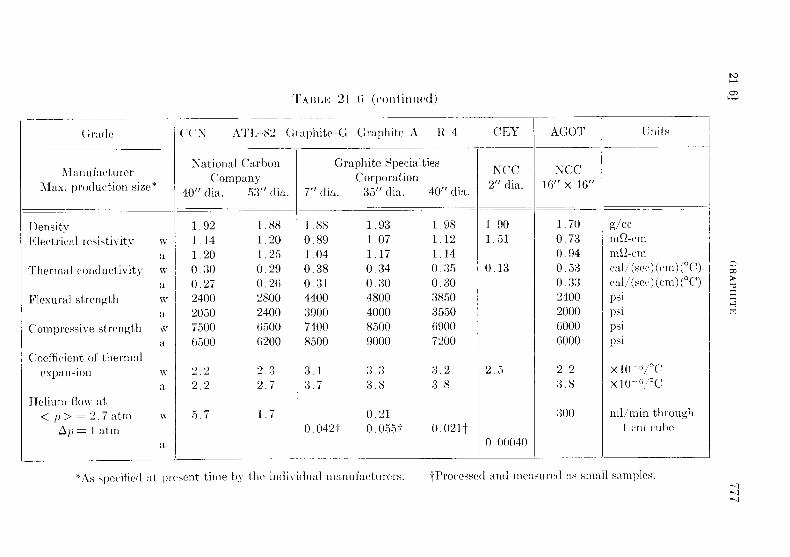
TABL1? 21 - G (cont.InUe(j)
Grade
40
('CNN AT1r-82 Graphite-G Graphite-A R 4
CEY AGOT Units
National CarbonCompany
Graphite SpecialtiesI' CC2" dia . 16"
N CCX 16"
ManufacturerMax. production size * 7" dia .
Corporationp35" dia .
40" dia .dia .
53" dia .
1 .92
1 .881 .14
1 .201 .20
1 .250 .30
0 .290 .27
0 .262400
28002050
24007500
65006500
6200
2 .2
2 .32 .2
2 .7
5 .7
1 .7
1 .880 .891 .040 .380 .314400390074008500
3 .13 .7
0 .0421
1 .93
1 .981 .07
1 .121 .17
1 .140 .34
0 .350 .30
0 .304800
38504000
35508500
69009000
7200
3 .3
3 .23 .8
3 .8
0 .210 .055t
0.021t
1 .901 .51
0 .13
2 .5
0 .00040
1 .700 .730 .940 .530 .332400200060006000
2 .23 .8
300
g/ccnh -cmme-cmcall/ (sec) (cm) ( ° C)cal/ (sec) (cm) ( °C)psipsipsipsi
X 10X 10-°/ °C
nil/ min throughI cm cube
DensityElectrical resistivity
Thermal conductivity
Flexural strength
Compressive strength
Coefficient of thermalexpansion
Helium flow atp > = 2 .7 atrnOp = 1 Am
wawawawa
wa
w
*As specified at present time by the individual manufacturers .
tProcessed and measured as small samples .
is predictable from the chemical thermodynamic data. An experiment inwhich graphite was contacted with 1000 ppm U, 50 pprii Zr, and 300 ppmMg in BI at 1000 °C for 8 hr showed only a single intense x-ray diffractionline corresponding to the most intense line for ZrC . The x-ray analysiswas carried out after the adherent bismuth was removed from the samplesby mercury rinsing .
These experiments indicate that the reaction of uranium with graphiteis not likely to, occur under the LMFR operational conditions and can beprevented by the addition of zirconium to the bismuth .
Zirconium and titanium reactions with graphite . Since zirconium and pos-sibly some titanium will be present in the bismuth, reactions of thesematerials with graphite have been investigated . As described above, zir-conium reacts to form the carbide with a strong negative free energy. Attemperatures around 550°C, ZrC and solid solutions of ZrC and ZrN havebeen identified on graphite surfaces contacted with bismuth solutions con-taining 130 ppm Zr .On the other hand, no reaction between graphite and 1600 ppm Ti in
Bi solutions has been observed up to 800 °C for contact times up to 170 hr .A strong TiC x-ray pattern and a less intense ZrC-ZrN solution patternwere observed on graphite contacted with approximately 0 .27 Ti and0.27 Zr in Bi at 1250 °C for 44 hr .
When steel samples are reacted with U-Bi fuels containing zirconiumand magnesium, the x-ray patterns of the surface are those for pure orvery nearly pure nitrides or carbides . When graphite is contacted with thefuel, however, solid solutions of the carbide and nitride are often found .The unit cells vary from 4.567 Kx* to 4.685 Kx for the zirconium com-pounds and from 4.237 Kx to 4 .320 Kx for the titanium compounds . Theseparameters are low for complete carbon carbide structures .
Parameters for carbon-deficient carbide structures have been reported inthe literature [13] . For ZrC the reported ao varied from 4.376 Kx at 20atomic percent C to 4 .67 Kx at 50 atomic percent C. However, up to thepresent time no evidence of carbon deficient structures has been observedin studying the graphite-fuel experiments . The low parameters are insteadbelieved due to nitrogen replacing the carbon atoms in the carbide lattice(NaCl-type). Parameters for such solid carbide-nitride solutions are de-scribed by Duwez and Odell [1] .
Fission product-graphite reactions . The products of uranium fission mayalso react chemically with graphite to form carbides . A series of experi-ments have shown that materials such as cerium will definitely react withgraphite. When 25 ppm Cc in bismuth was placed in contact with graph-ite at 700 °C for 110 hr, CeC2 was identified as a film on the graphite .Graphite contacted with 140 ppm Sm in bismuth at 800 °C for 140 hr, on
*Kx = 1000x units = 1 .00202 ± 0 .00003A .

the other hand, gave an x-ray diffraction pattern of the graphite surfacewhich could not be identified or indexed . Under similar reaction conditions,neodymium, barium, or beryllium in bismuth solutions have no reactionproduct. However, Miller [12] has shown by an autoradiograph techniquethat 180 ppm irradiated Nd in bismuth reacts with graphite at l 100 °C in100 hr, concentrating the radioactive Nd at the graphite-liquid metal in-terface . When the same experiment was repeated with the addition of100 ppm Zr to the solution, no Nd was identified at the graphite surface .This experiment indicates that zirconium will probably form the car-
bide and nitride preferentially to most fission products . However, furtherresearch is required to determine whether a zirconium carbide-nitride layeron the graphite can be depended upon to prevent the adhesion of the fissionproducts to the graphite surface. This point is not only important fromthe chemical and graphite surface point of view, but is also important fromthe neutron economy point of view . To obtain the highest breeding ratio,the fission products, which are all fairly good neutron adsorbers, must beremoved from the graphite core soon after their formation . This is espe-cially true of samarium, which has a very high neutron absorption crosssection. Therefore, the experiments reported above on zirconium are quiteencouraging in that there is no trace of a samarium film on the graphite .
21-6.4 Radiation effects on graphite . The graphite core, in order toserve as moderator and container for the flowing fuel, must be stable toradiation . Fission recoils may cause spalling and reduction in the thermalconductivity that might increase the thermal stresses within the core struc-ture. The graphite must not adsorb large quantities of U or fission products .
A capsule test has been developed in which samples are irradiated in ahighly enriched U-Bi solution containing Mg and Zr inhibitors for studyof radiation effects on materials . The test has the advantage of attaininghigh temperatures (700 °C) and a high fission recoil density .
Graphite samples have been exposed in these capsules under conditionsgiven in Table 21-7 . Metallographic examination of these graphite sam-ple-~ indicates that there is no excessive spalling or corrosion .
However, some samples were treated with Bi containing Zr at 1300 °Cto obtain 10- to 30-micron ZrN-ZrC layers on the graphite prior to irradia-tion, and postirradiation examination indicated some change of this layer .The cause of these effects is still being determined .
The effect of neutrons on the growth and thermal conductivity proper-ties of special low-permeability grades of graphite has been measured .Three sets of samples have been irradiated to exposures as great as 5 X 10 20
thermal neutrons/cm 2 in the temperature range 400 to 475°C. Results ofthese tests are listed in Table 21-8 . The change in physical length of thegraphite is primarily contraction and should not present a major engineer-ing problem .
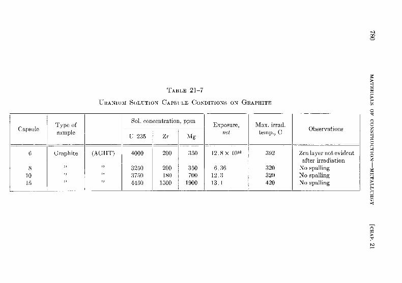
TABLE 21-7
URANIUM SOLUTION CAPSULE CONDITIONS ON GRAPHITE
CapsuleType ofsample
Sol. concentration, ppm Exposure,nvt
Max. irrad .temp., C Observations
U-235 Zr Mg
6 Graphite (AGHT) 4000 200 350 12 .8 x 1018 392 Zrn layer not evidentafter irradiation
8 3250 200 350 6 .36 320 No spalling10 3750 180 700 12 .3 320 No spalling15 4450 1500 1900 13 .1 420 No spalling
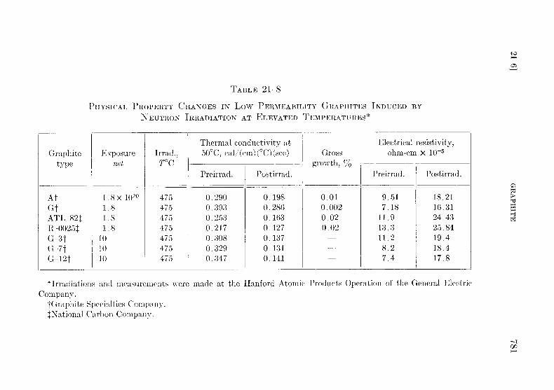
TABLE 21-8
PHYSICAL PROPERTY CHANGES IN Low PERMEABILITY GRAPHITES INDUCED BYNEUTRON IRRADIATION AT ELEVATED TEMPERATURES*
Graphitetype
Exposurenvt
Irrad .,T°C
Thermal conductivity at50°C, cal/(cm) (°C) (sec) Gross
growth, %
Electrical resistivity,ohm-cm x 10-5
Preirrad . Postirrad .Preirrad . Postirrad .
AtGtAT7-821R-0025tG-3tG -7tG-12t
1 .8 x 10201 .81 .81 .8
101010
475475475475475475475
0 .2900 .3930 .2530 .2170 .3080 .3290 .347
0 .1980 .2860 .1630 .1270 .1370 .1310 .141
0 .010 .0020 .020 .02
9 .517 .18
11 .913 .311 .28 .27 .4
18 .2116 .3124.4325 .8419 .418 .417 .8
*Irradiations and measurements were made at the Hanford Atomic Products Operation of the General ElectricCompany .
tGraphite Specialties Company .National Carbon Company .
On the other hand, the neutrons reduced the thermal conductivity by25 to 3570 of the preirradiation value . Moreover, some of these graphiteshad a preirradiation conductivity only 65% that of the usual reactor-gradegraphite . The combination of low permeability and neutron irradiationtherefore reduces the thermal conductivity to 507 that of the usual reactor-grade graphites .
Bismuth penetration into graphite permits the diffusion of some uraniuminto the graphite. The resulting fission recoil particles may further reducethe thermal conductivity of graphite . Tests are now under way to deter-mine the degree of damage produced .
21-6.5 Bismuth permeation and diffusion into graphite . Early in thework on the Liquid Metal Fuel Reactor it was recognized that a specialtype of graphite was required if it were to be both a moderator and a con-tainer for the reactor fluid . Such an impermeable graphite would have notonly the usual advantages of being both structural material and moderator,but would also not hold up quantities of coolant or fuel, with resultingdecreased neutron efficiency and control . Besides these characteristics,because the design fluxes are of the order of 10 15 n/(cm2 ) ( see) it is necessarythat the graphite have a high degree of resistance to radiation damage,specifically to physical growth and reduction in thermal conductivity .
In considering impermeable graphite, two characteristics of the graphiteare concerned : liquid pickup and permeability . Liquid pickup refers tothe amount of fluid which is held in the interior pore volume of the graphitein the manner of a sponge. Permeability is the rate at which a fluid can bemade to flow through the graphite . Both these properties depend primarilyon the accessible void volume and the pore spectrum .
In research work on graphite, it is customary to divide the size of poresinto two categories : macro pores larger than 1 micron and averaging 2 .5microns in radius, and micro pores with radii less than 1 micron and pre-dominantly below 0 .5 micron .
The development of new types of "impermeable" graphite has necessi-tated an examination and improvement of manufacturing processes con-current with experiments on bismuth uptake [14] .
The classic process of graphite manufacture is based on cokes and pitchbinders, baking and pitch reimpregnations, and finally graphitization .Around this scheme has evolved a complex technology involving carefulparticle and flour sizing to obtain optimum compaction, elaborate bakingand graphitizing schedules, and extremes of pressure vacuum treatments .The production of the new relatively impermeable grades was made pos-sible by three significant advances over the older technology : (1) the abilityto use raw materials of more advanced form, including graphites and blacksof various types, (2) impregnation techniques now span a variety of resins
with various viscosity and wetting properties, and (3) new forming tech-niques permit much more uniform and finer-grained artificial graphites .This last includes, in particular, the development of pressure baking, whereheat is applied by passing electric current through the carbon in the moldand under pressure .
The conventional pitch-type impregnation has the effect of increasingdensity without markedly reducing permeability . This is apparently dueto the tendency of the pitch to coke out only in the voids of large effectivepore radius . Conversely, the newer impregnating materials, with theirlower viscosities and increased wetting, tend to block the pores themselvesas well as the larger open volumes . Consequently, there is no general rela-tionship between density and permeability . Several conclusions may bedrawn : (1) The newer impregnates primarily attack the macropore distri-bution and shift it from the 1- to 5-micron range into the submicron range .(2) Optimum particle packing in the original base material is, in general,not an advantage upon reimpregnation. (3) It is essential to use base ma-terials in which the long tail at high pore radii is missing . The relativelyminor effect of the present impregnates upon the micropore distributiondemonstrates that the present materials, markedly improved as they are,do not as yet represent the achievable ultimate .
The amount of bismuth uptake in graphite is probably the most im-portant property concerned in evaluating the graphite, and was one of thefirst investigated. For this purpose, a simple pot arrangement is used tohold samples of graphite in molten bismuth at pressures from vacuum to550 psi and at temperatures from 550°C . The graphite samples (0.5-in .OD and 1.75-in. long) are outgassed in a vacuum at 550 °C and then sub-merged in the bismuth . Helium pressure is then applied to the molten bis-muth. The amount of bismuth uptake into the graphite is determined bythe difference in the density of the sample before and after submersion .The accuracy of this measurement is within 0 .01 g bismuth per cc graphite .The degree of bismuth uptake by graphite as a function of time, de-
termined at a pressure of 250 psi at 550 °C, is shown in Fig . 21-13. As wasmentioned above, there is no correlation between uptake and graphitedensity . The densities of these graphites range from 1 .73 to 1 .92 g/cc . Thetotal percent of void volumes in the impregnated grades varies from 16 .0to 19.0'_( of the bulk volume . Of these totals, the inaccessible volumesrange from 6 to 10% . Although samples EY-9 and ATL-82 have nearlythe same density, the bismuth absorption differs by as much as a factor of:3 because of the difference in pore spectrum .As can be seen from the figure, the amount of bismuth uptake varies as
a function of time . This behavior was obtained using separate samples foreach point on a curve and also by measuring the same sample at varioustime intervals. In making determinations, considerable oscillation about
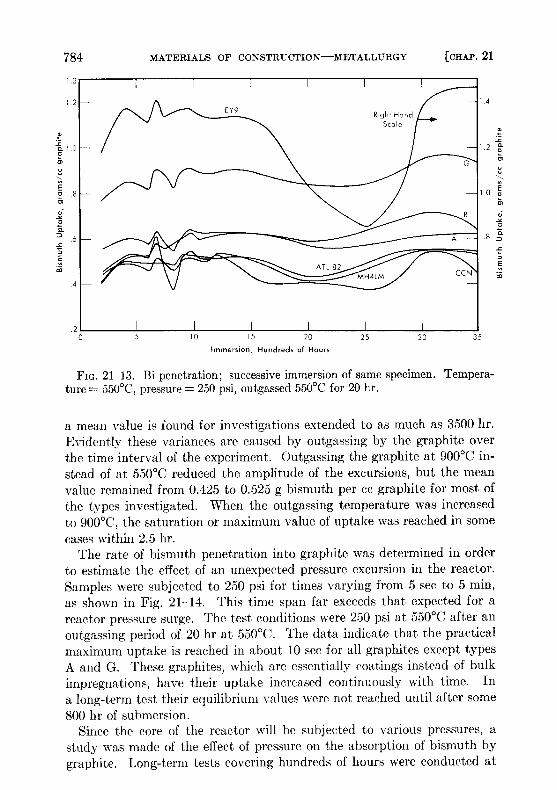
FIG. 21-13 . Bi penetration ; successive immersion of same specimen . Tempera-ture = 550 °C, pressure = 250 psi, outgassed 550 °C for 20 hr .
a mean value is found for investigations extended to as much as 3500 hr .Evidently these variances are caused by outgassing by the graphite overthe time interval of the experiment . Outgassing the graphite at 900 °C in-stead of at 550 °C reduced the amplitude of the excursions, but the meanvalue remained from 0 .425 to 0.525 g bismuth per cc graphite for most ofthe types investigated . When the outgassing temperature was increasedto 900°C, the saturation or maximum value of uptake was reached in somecases within 2 .5 hr .
The rate of bismuth penetration into graphite was determined in orderto estimate the effect of an unexpected pressure excursion in the reactor .Samples were subjected to 250 psi for times varying from 5 sec to 5 min,as shown in Fig. 21-14. This time span far exceeds that expected for areactor pressure surge . The test conditions were 250 psi at 550 °C after anoutgassing period of 20 hr at 550 °C. The data indicate that the practicalmaximum uptake is reached in about 10 sec for all graphites except typesA and G. These graphites, which are essentially coatings instead of bulkimpregnations, have their uptake increased continuously with time . Ina long-term test their equilibrium values were not reached until after some800 hr of submersion .
Since the core of the reactor will be subjected to various pressures, astudy was made of the effect of pressure on the absorption of bismuth bygraphite. Long-term tests covering hundreds of hours were conducted at
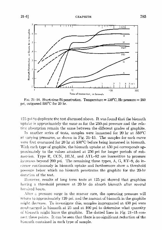
FIG. 21-14 . Short-time Bi penetration . Temperature = 550°C, He pressure = 250psi, outgassed 550 °C for 20 hr .
125 psi to duplicate the test discussed above. It was found that the bismuthuptake is approximately the same as for the 250-psi pressure and the rela-tive absorption remain the same between the different grades of graphite .
In another series of tests, samples were immersed for 20 hr at 550°Cat varying pressures, as shown in Fig . 21-15 . The samples for each curvewere first evacuated for 20 hr at 550 °C before being immersed in bismuth .With each type of graphite, the bismuth uptake at 450 psi corresponds ap-proximately to the values attained at 250 psi for longer periods of sub-mersion . Type R, CCN, HLM, and ATL-82 are insensitive to pressureincreases beyond 200 psi . The remaining three types, A, G, EY-9, do in-crease continuously in bismuth uptake and furthermore show a thresholdpressure below which no bismuth penetrates the graphite for the 20-hrduration of the test .
However, results of long term tests at 125 psi showed that graphiteshaving a threshold pressure at 20 hr do absorb bismuth after severalhundred hours .
After a pressure surge in the reactor core, the operating pressure willreturn to approximately 120 psi, and the amount of bismuth in the graphitemight decrease . To investigate this, samples impregnated at 450 psi wereresuhmerged in bismuth at 25 and at 100 psi to determine what quantityof bismuth might leave the graphite . The dotted lines in Fig. 21-15 con-nect these points . It can be seen that there is no significant reduction of thebismuth contained in each type of sample .

FIG . 21-15 . Effect of pressure on Bi penetration ; successive immersions of 20hr. Temperature= 550°C, outgassed 550°C for 20 hr. Dashed lines for reducedpressure after 450-psi impregnation .
Calculations of the percent of voids filled with bismuth were made forthe maximum bismuth uptake obtained in the experiments shown inFig. 21-15. Table 21-9 gives these calculated values for the approximatesaturation level reached . In this table, the last graphite, AGOT, is theconventional reactor graphite . The 100% filling of the voids is obviously agood check of the assumption that it is quite permeable. All the othergraphites are impermeable grades under development by various com-panies . The percent voids filled for these graphites do not represent totalsaturation of the accessible voids . Rather, these values show that about1/3 to 1/2 of the accessible void volumes have been filled in these experi-ments .
In studying threshold penetration effect, surface tensions of bismuth onvarious surfaces of graphite were measured (Table 21-10) . Although dif-fering from the accepted values, these determinations probably representmore closely the actual circumstances in a reactor core . In none of the fourcases was wetting of the graphite obtained by the bismuth or bismuthsolution .
Uranium diffusion into bismuth in graphite pores . Since a certain amountof fuel absorption will have to be tolerated with the graphites now avail-able, it is essential to measure the diffusion of uranium into graphite by
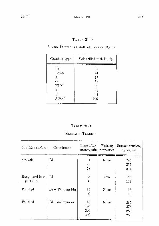
TABLE 21-9
VOIDS FILLED AT 450 PSI AFTER 20 HR .
Graphite type Voids filled with Bi, QJo
100 37E Y-9 44A 17G 37HLM 32M 23R 32AGOT 100
TABLE 21-10
SURFACE TENSIONS
Graphite surfaceG Constituents Time aftercontact, min
Wettingproperties
Surface tension,dynes/cm
Smooth Bi 1 None 27629 25778 241
Rough and loose Bi 5 None 153partia-les 60 142
Polislied Bi + 350 ppm Mg 15 None 6690 66
Polished
Bi + 350 ppm Zr 15 None 285120 275240 282360 283
means of the bismuth solution . Experiments to measure this effect havebeen made. This was done by first impregnating graphite with bismuth so-lution containing magnesium and/or zirconium . After bismuth impregna-tion at a given pressure, uranium was added to the solution and the graph-ite allowed to soak in the bismuth solution for a period of time . The amountof uranium which diffused into the graphite was measured by sectioningthe graphite and analyzing for uranium concentration as a function ofdistance from the surface of the sample . These experiments were run at550°C with a pressure of 200 psi . The graphite was first allowed to soakin the bismuth solution for 90 hr ; then the uranium was added and theconditions were maintained for the duration of the experiment . Results oftwo experiments are given in Table 21-11 . In the first experiment, thebismuth contained 390 ppm Mg and 1000 ppm IT . The uranium concen-tration in the graphite specimen was found to be less than in the meltsolution and decreased from the sample face inwards .
The second experiment was performed exactly like the first except thatno magnesium was present . The graphite specimen (Great Lakes TypeHLM) absorbs less bismuth than the EY-9 graphite used in the first ex-periment. However, the uranium concentration near the surface of thespecimen built up to an amount considerably greater than that initially inthe solution, and the concentration gradient is much steeper than wasfound when magnesium was present in the solution. This high value forthe uranium-to-bismuth ratio near the interface may be explained byassuming that uranium reacted with impurities present on the graphitesurfaces. Apparently when magnesium is present in the solution it reactspreferentially with these impurities .
These experiments definitely show that uranium and other solutespresent in the bismuth can be expected to diffuse into the graphite as faras the bismuth has penetrated . For the graphites now at hand, this meansdiffusion through the entire thickness of the graphite for the long-termexposures contemplated in a reactor core . Of course, since the diffusion ofuranium itself takes considerable time, fission will convert it to other prod-ucts before it has an opportunity to diffuse many inches into the graphite .The effect of diffusion of the various solutes and fuel into graphite onneutron economy and reactor operational characteristics is recognized, andstudies have to be made in large-scale experiments .
In general, it is believed that the graphites at hand will meet the require-ments for the first experiment of an LMFR reactor . It is already possibleto produce some of these in sizes as large as 40 to 60 in . in diameter. Asthis development progresses, graphites of greater impermeability will beproduced . Improvements in graphite have taken place steadily, andmarkedly improved materials are anticipated in the future .

TABLE 21-11
URANIUM DIFFUSION INTO GRAPHITE
Specimen no . Distance, in . Bi, % AN, ppm U, ppm
A. EY-9 Graphite
1 0 .0312 32 .2 1150 9002 0 .0937 30 .5 1050 8403 0 .1562 29 .6 750 8104 0 .250 28 .0 800 7605 0 .500 26 .0 820 740
B. HLAZ Graphite
1 0 .0312 16 .35 56002 0 .0937 16 .87 26303 0 .1562 16 .38 4604 0 .250 16 .78 705 0 .500 17 .78 30
REFERENCES
1 . P . Duwuz and F . ODELL, Phase Relationships in the Binary Systems ofNitrides and Carbides of Zirconium, Columbium, Titanium, and Vanadium,J. Electrochem. Soc . 97, 299-304 (1950) .
2. D . T . KEATING and 0. F . KAMMERER, Film Thickness Determination fromSubstrate X-ray Reflections, Rev . Sci . Instr . 29, 34 (1958) .
3 . L . S . DARKEN et al ., Solubility of Nitrogen in Gamma Iron and the Effectof Alloying Constituents Aluminum Nitride Precipitation, J . Metals 3, 1174-1179 (1951) .
4 . J. R . WEEKS and D . H . GURINSKY, Solid Metal-Liquid Metal Reactions inBismuth and Sodium, in A S 1I Symposium on Liquid Metals and Solidification,ed. by B. Chalmers. Cleveland, Ohio : The American Society for Metals, 1958 .
5. 0 . F . KAMMERER et al ., Zirconium and Titanium Inhibit Corrosion andMass Transfer of Steels by Liquid Heavy Metals, Trans. Met. Soc. AIMS 212,20-25 (1958) .
6. G. W . HORSLEY and J. T . MASKREY, The Corrosion of 2) % Cr-1% MoSteel by Liquid Bismuth, Report AERE M/R-2343, Great Britain, AtomicEnergy Research Establishment, 1957 .
7. J. R. WEEKS et al ., Corrosion Problems with Bismuth-Uranium Fuels, inProceedings of the International Conference on the Peaceful Uses of Atomic Energy,Vol. 9. New York: United Nations, 1956 (P/118, pp . 341-355) ; D. H . GURINSKYand G . J . DIENES (Eds .), Nuclear Fuels . Princeton, N . J . : 1) . Van NostrandCo., Inc ., 1956. (Chap. XIII) ; J. R . WEEKS, Metallurgical Studies on LiquidBismuth and Bismuth Alloys for Reactor Fuels or Coolants, in Progress inNuclear Energy, Series IV, Technology and Engineering, Vol . I . New York :Pergamon Press, 1956 . (pp . 378-408)
8 . W. C . LESLIE and M. G . FONTANA, Mechanism of the Rapid Oxidation ofHigh Temperature, High Strength Alloys Containing Molybdenum, Trans .Am. Soc . Metals 41, 1213 (1949) .
9 . L. S . MARKS (Ed .), Mechanical Engineers Handbook . 4th ed. New York :McGraw-Hill Book Company, Inc ., 1941 . (p. 232)
10 . W. E. MARKERT, JR ., personal communication to J . R. Weeks, Mar . 20,
1958 .11 . M. W . MALLETT et al ., The Uranium-Carbon System, US AEC Report
AECD-3226, Battelle Memorial Institute, 1951 ; The Reactor Handbook, Vol . 3,General Properties of _1laterials, USAEC Report AECD-3647, 1955 . (p . 316)
12 . TV. E . MILLER and J. R . WEEKS, Reactions between LITER Fuel and ItsContainer Materials, US AEC Report BNL-2913, Brookhaven National Labora-tory, 1956 .
13. G. V . SAMSONov and N. S . ROZINOVA, Some Physicochemical Propertiesof Zirconium-Carbon Alloys, Izvest . Sektora Fiz .-Khiin . Anal. Inst . Obshchei .Neorg. Khim. Akad. Nauk. S.S .S.R. 27, 126-132 (1956) .
14. W . P . EATHERLY et al ., Physical Properties of New Graphite Materials forSpecial Nuclear Applications, paper prepared for the Second InternationalConference on the Peaceful Uses of Atomic Energy, Geneva, 1958 .