fiji thermal and plasma atomic layer deposition system ... · pdf fileald system ucla...
TRANSCRIPT
ALD System UCLA Nanoelectronic Facility
1
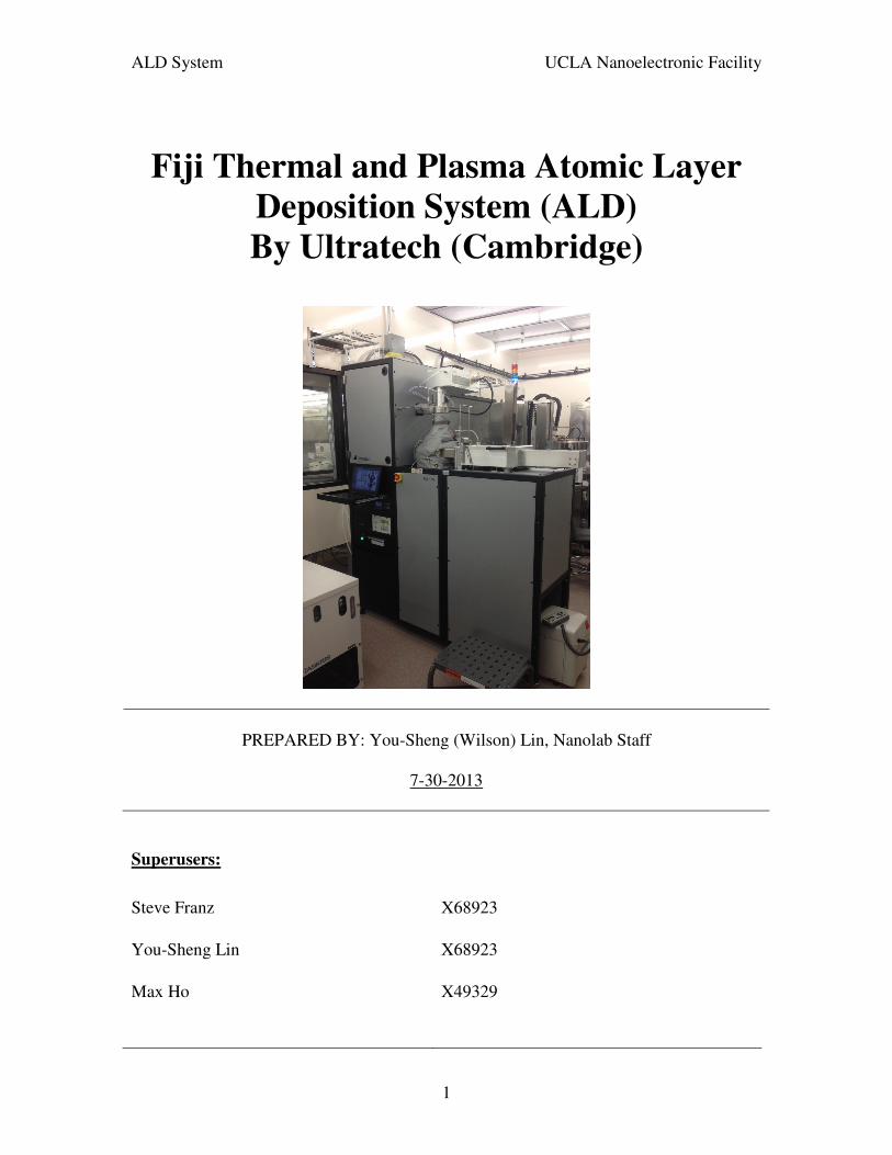
Fiji Thermal and Plasma Atomic Layer
Deposition System (ALD)
By Ultratech (Cambridge)
PREPARED BY: You-Sheng (Wilson) Lin, Nanolab Staff
7-30-2013
Superusers:
Steve Franz X68923
You-Sheng Lin X68923
Max Ho X49329
ALD System UCLA Nanoelectronic Facility
2
1.0 SAFETY RULES
To avoid a fire or explosion, follow these instructions.
• Do not place flammable materials underneath, on or near the unit. Do not place
paperwork, wipes etc. on or near the unit.
• Do not run the system unattended; do not run the system overnight.
• Do not heat materials to temperatures above those recommended by the
manufacturer. Make sure heat monitoring and limiting devices are working
properly. Note the maximum temperature settings for different parts.
• ALD pulse valves are rated to 150oC and should not be heated above that
temperature. Center heater maximum temperature is 400oC, while outer heater
should not be set higher then 250oC because of the O-ring. The tee and flexible
bellows of pumping line should not be heated above 150oC.
• Temperature of the precursors should not exceed safety or decomposition
temperature of the chemical used. Maximum for the precursor heater jacket is
200oC.
ALD System UCLA Nanoelectronic Facility
3
2.0 OVERVIEW
Principle of Al2O3 formation
Atomic Layer Deposition (ALD) is a technique that allows growth of thin films, atomic
layer by layer. Deposition of Al2O3 from water and trimethylaluminum (TMA) precursors
will be used to illustrate the principle of ALD. Recipes for other materials can be found
in the literature.
The chemical principle of Al2O3 growth from water and TMA is outlined in 5 steps
shown in Figure 1.
Step. 1: Put in a sample which is hydroxylated from exposure to air, oxygen or ozone
(Figure 1A).
Step 2: Pulse the TMA precursor; TMA will react with the OH groups on the surface.
TMA does not react with itself and the monolayer formed passivates the surface (Figure
1B, 1C).
Step 3: Remove unreacted TMA molecules by evacuation and/or purging with nitrogen
(Figure 1D).
Step 4: Pulse water (H2O) into the reactor. This will remove the CH3 groups, create Al-
O-Al bridges, and passivate surface with Al-OH. CH4 (methane) is formed as a gaseous
byproduct (Figure 1E, 1F).
Step 5: Remove unreacted H2O and CH4 molecules by evacuation and/or purging with
nitrogen (Figure 1G).
Steps (1)-(5) form a cycle. Each cycle produces a maximum of 1.1 Å of Al2O3 depending
on temperature.Thus, 100 cycles produces 11 nm of Al2O3.
ALD System UCLA Nanoelectronic Facility
4
Similar reaction can be expected for HfO2 by using Tetrakis(dimethylamido)hafnium
(IV).
WARNING:
Trimethylaluminum (TMA) is a liquid at room temperature and is pyrophoric. This
means that it burns upon exposure to air.

ALD System UCLA Nanoelectronic Facility
5
ALD System UCLA Nanoelectronic Facility
6
3.0 SYSTEM INFORMATION
The ALD system in the UCLA Nanoelectronic Facility is a ULTRATECH (Cambridge
NanoTech Fiji F200) equipped with a heated process chamber, remote plasma source,
turbomolecular pump, and automated load lock for transferring substrates. The system is
primarily intended for the deposition of a variety of thin films, including metals, oxides,
and nitrides. Typical film thicknesses are monolayers up to tens of nanometers. Thicker
films may be deposited but due to the low deposition rates (~ 3−20 nm/h) these films
would required deposition times of several hours.
Some key features are as follows.
• Highly conformable, well controlled layer by layer film deposition.
• Multi-layer film stacks possible.
• Aspect ratios of up to 450:1 in thermal mode or 20:1 in plasma mode are possible.
• Substrates up to 200 mm in diameter and 6 mm thick can be accommodated.
• Substrates may be heated up to 400°C, but most recipes only required up to 300°C.
• Process chamber turbomolecular pump provides a base pressure ~ 2 x 10⁻⁵ Torr.
• Load lock chamber with automated transfer of substrates into the process chamber.
• All depositions are performed from recipes.
There are two main modes of operation:
1. Continuously flowing nitrogen carrier gas while pulsing (adding) precursor and
pumping continuously
2. Pulsing precursors with stop valve closed and pumping in between pulses.

ALD System UCLA Nanoelectronic Facility
7
3.1. System Overview:
3.2. System Control:
All controls for processing recipes, system startup/shutdown, configuration, and the
settings are performed via the supplied Windows platform laptop computer. The
computer is stored in a “computer drawer” in the electronics cabinet located below the
gas box:
Precursor bottles Chamber
Load Lock Computer Drawer EMO
Mechanical Pump
Chiller
ALD System UCLA Nanoelectronic Facility
8
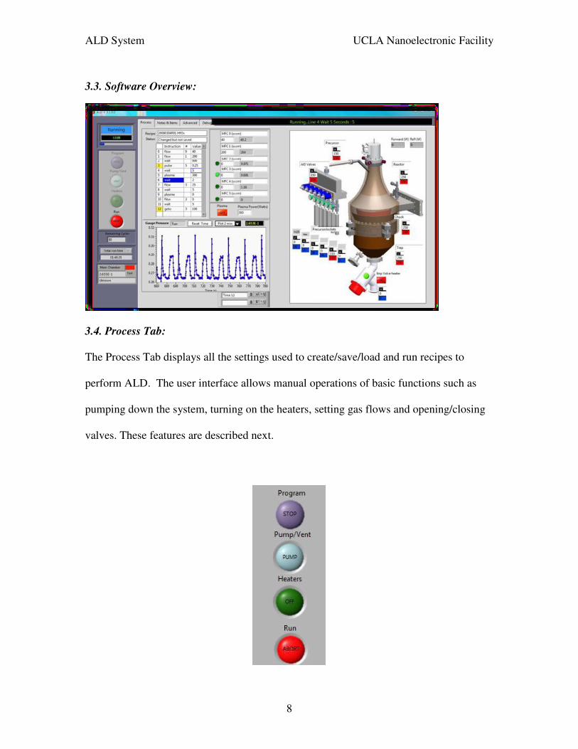
3.3. Software Overview:
3.4. Process Tab:
The Process Tab displays all the settings used to create/save/load and run recipes to
perform ALD. The user interface allows manual operations of basic functions such as
pumping down the system, turning on the heaters, setting gas flows and opening/closing
valves. These features are described next.

ALD System UCLA Nanoelectronic Facility
9
Program Switch
Stops the Fiji software and turns off all outputs. Typically this button is not used except
to exit the system software prior to shutting down the system. For systems equipped with
a turbo, stopping the program will automatically decelerate the turbo before exiting.
Pump/Vent Toggle Switch (Radials display ‘next-state’ rather than ‘current state):
This button is disabled on systems with load/locks. Refer to the Vacuum System tab.
PUMP - pumps the system down to base pressure
VENT - vents the process chamber to atmospheric pressure
Closes the main stop valve to isolate the process chamber from the vacuum pump and
then opens the main chamber vent valve. A window prompts the user to click OK to
close the main chamber vent valve once atmospheric pressure is achieved.
Heaters Toggle Switch (Radials display ‘next-state’ rather than ‘current state):
ON - turns heaters ON (to default setpoints)
OFF - turns heaters OFF (all temperature setpoints are set to °C)
Run Toggle Switch (Radials display ‘next-state’ rather than ‘current state):
START - runs the recipe program
ABORT - aborts a current recipe run
When a process is running, “Program”, “Pump/Vent” and “Heaters” buttons are grey and
not clickable. To abort a run, simply click on Run ABORT button.
ALD System UCLA Nanoelectronic Facility
10
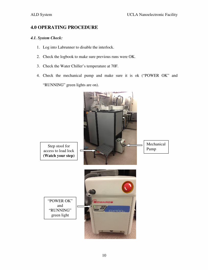
4.0 OPERATING PROCEDURE
4.1. System Check:
1. Log into Labrunner to disable the interlock.
2. Check the logbook to make sure previous runs were OK.
3. Check the Water Chiller’s temperature at 70F.
4. Check the mechanical pump and make sure it is ok (“POWER OK” and
“RUNNING” green lights are on).
Mechanical Pump
“POWER OK” and
“RUNNING” green light
Step stool for access to load lock (Watch your step)
ALD System UCLA Nanoelectronic Facility
11
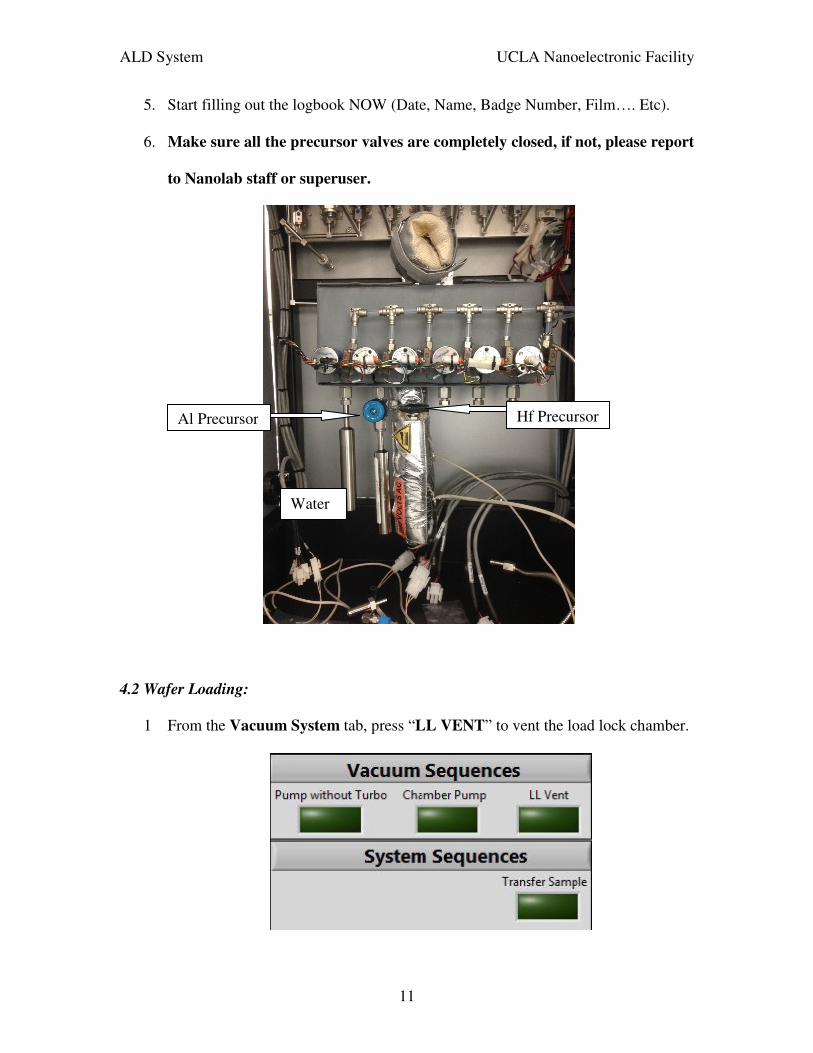
5. Start filling out the logbook NOW (Date, Name, Badge Number, Film…. Etc).
6. Make sure all the precursor valves are completely closed, if not, please report
to Nanolab staff or superuser.
4.2 Wafer Loading:
1 From the Vacuum System tab, press “LL VENT” to vent the load lock chamber.
Water
Al Precursor Hf Precursor

ALD System UCLA Nanoelectronic Facility
12
2 Wait 3 to 5 minutes until the load lock is completely vented. (Check the gap at load lock door).
3 Once the chamber is completely vented, Press OK on the software popup screen
to turn off the load lock vent valve.
4 Lift the load lock door up when atmospheric pressure is reached.
Under Vacuum
Vented to Atmosphere
ALD System UCLA Nanoelectronic Facility
13
5 Load your wafer. Use the step stool to help reach the load lock door (Watch your
steps when on the step stool)
6 After loading your sample, close the door down.
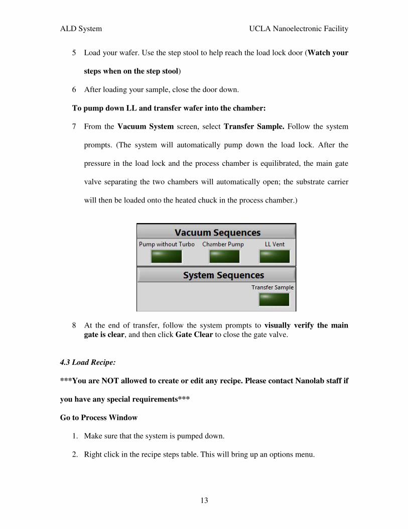
To pump down LL and transfer wafer into the chamber:
7 From the Vacuum System screen, select Transfer Sample. Follow the system
prompts. (The system will automatically pump down the load lock. After the
pressure in the load lock and the process chamber is equilibrated, the main gate
valve separating the two chambers will automatically open; the substrate carrier
will then be loaded onto the heated chuck in the process chamber.)
8 At the end of transfer, follow the system prompts to visually verify the main
gate is clear, and then click Gate Clear to close the gate valve.
4.3 Load Recipe:
***You are NOT allowed to create or edit any recipe. Please contact Nanolab staff if
you have any special requirements***
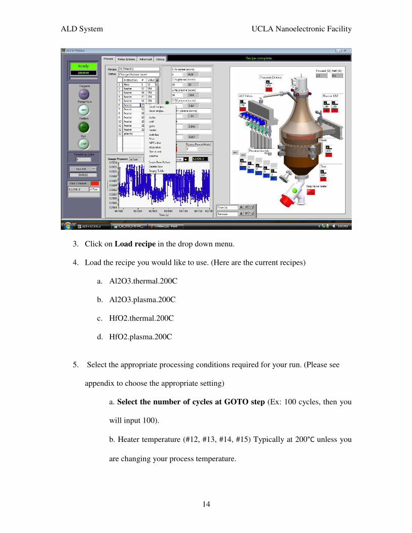
Go to Process Window
1. Make sure that the system is pumped down.
2. Right click in the recipe steps table. This will bring up an options menu.
ALD System UCLA Nanoelectronic Facility
14
3. Click on Load recipe in the drop down menu.
4. Load the recipe you would like to use. (Here are the current recipes)
a. Al2O3.thermal.200C
b. Al2O3.plasma.200C
c. HfO2.thermal.200C
d. HfO2.plasma.200C
5. Select the appropriate processing conditions required for your run. (Please see
appendix to choose the appropriate setting)
a. Select the number of cycles at GOTO step (Ex: 100 cycles, then you
will input 100).
b. Heater temperature (#12, #13, #14, #15) Typically at 200°C unless you
are changing your process temperature.

ALD System UCLA Nanoelectronic Facility
15
c. Precursor Delivery line (#16 at 150°C) and precursor manifold (#17 at
150°C).
d. Precursor bottle temperature (TMA #18 @ room temperature – set at 0)
and (Hf 19 @ 65°C).
e. Purge time and wait time (Please see appendix).
f. Set APC at 9% .
6. Double check all the steps with the appendix.
7. Do not overwrite the standard recipe. If you want to save any recipe, please
create a new folder (make sure to discuss your process with nanolab staff).
8. Wait 10 minutes for the substrate/chamber to stabilize the temperature.
(Depending on process temperature and precursor)
9. Open the appropriate precursor valve.
10. Press Start to run the recipe.
11. Click Yes in the recipe start confirmation window.
12. Monitor the system to make sure your process is going well.
13. Record processing temperature and observe pulse time/process pressure.
14. Once complete, close precursor valve.
ALD System UCLA Nanoelectronic Facility
16
4.4 Unload the wafer after deposition:
1. From the Vacuum System screen, select Transfer Sample. The substrate
carrier should be automatically transferred to the Load Lock.
2. Wait for your substrate to cool to near room temperature (Ex: for substrates
which were heated to 200°C, allow at least 20 minutes).
Go to Vacuum System screen, press LL Vent.
3. Wait 2-3 minutes for the LL to vent. During this interval, the load lock pressure
should rise to 760 Torr and a dialogue box will appear requesting
acknowledgement that the LL is at atmospheric pressure. DO NOT
acknowledge yet.
4. Gently try to lift the LL door. If it will not lift easily, wait another minute and
try again. Repeat until it lifts easily.
5. Once the LL door can be opened easily, press OK in the dialogue box to
acknowledge that the LL is at atmospheric pressure.
6. Fully open the LL door.
7. Approach the substrate carrier carefully in case it is hot. If it is, allow it to cool.
8. Remove your wafer from the substrate carrier.
9. Close the LL door.
10. From the Vacuum System screen, select PumpChamber & LL without
Turbo in order to pump down both the chamber and load lock.
4.5 Cleaning the ALD valve and manifold recipe (approximate 2 minutes)
1. Make sure all precursor valves are close.

ALD System UCLA Nanoelectronic Facility
17
2. Go to Process Window and right click in the recipe steps table.
3. Select “Al_Headpurge” or “Hf_Headpurge” recipe depending on which
precursor you used.
4. Double check to make sure all precursor valves are close.
5. Make sure both Door Purge and Main Turbo Purge are on by clicking on them
(Should be light green).
6. Press Start to run recipe.
7. After your run is completed, make sure the following settings are as follows:
a. Heater temperature setting
i. All precursor bottle temperature = 0
ii. Heater Temperature (#12, #13, #14, #15) = 200°C
iii. Precursor Delivery line (#16 at 150°C)
iv. Precursor manifold (#17 at 150°C)
b. Argon idle flows:
i. MFC0 Ar Carrier = 5 sccm
ii. MFC1 Ar Plasma = 10 sccm
c. Turn off all 2 purges; make sure they are dark green (on the Vacuum
System screen).
i. Door Purge
ii. Main Turbo Purge
ALD System UCLA Nanoelectronic Facility
18
4.6. Logbook and Interlock
1. Fill in all the information in the logbook.
a. User name and usage time
b. All temperatures and process times
c. Use ellipsometer to measure the film thickness and Index of reflection
2. Log out from the labrunner
ALD System UCLA Nanoelectronic Facility
19
Appendix:
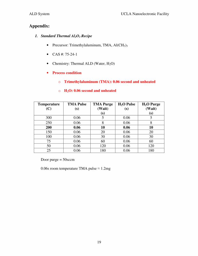
1. Standard Thermal Al2O3 Recipe
• Precursor: Trimethylaluminum, TMA, Al(CH3)3
• CAS #: 75-24-1
• Chemistry: Thermal ALD (Water, H2O)
• Process condition
o Trimethylaluminum (TMA): 0.06 second and unheated
o H2O: 0.06 second and unheated
Temperature
(C)
TMA Pulse
(s)
TMA Purge
(Wait)
(s)
H2O Pulse
(s)
H2O Purge
(Wait)
(s)
300 0.06 5 0.06 5 250 0.06 8 0.06 8 200 0.06 10 0.06 10
150 0.06 20 0.06 20 100 0.06 30 0.06 30 75 0.06 60 0.06 60 50 0.06 120 0.06 120 25 0.06 180 0.06 180
Door purge = 50sccm
0.06s room temperature TMA pulse ≈ 1.2mg
ALD System UCLA Nanoelectronic Facility
20
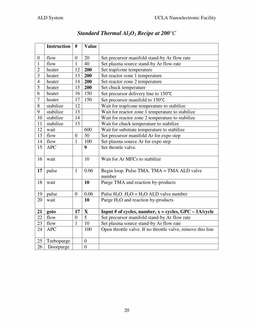
Standard Thermal Al2O3 Recipe at 200°C
Instruction # Value
0 flow 0 20 Set precursor manifold stand-by Ar flow rate 1 flow 1 40 Set plasma source stand-by Ar flow rate 2 heater 12 200 Set trap/cone temperature 3 heater 13 200 Set reactor zone 1 temperature 4 heater 14 200 Set reactor zone 2 temperature 5 heater 15 200 Set chuck temperature 6 heater 16 150 Set precursor delivery line to 150°C 7 heater 17 150 Set precursor manifold to 150°C 8 stabilize 12 Wait for trap/cone temperature to stabilize 9 stabilize 13 Wait for reactor zone 1 temperature to stabilize 10 stabilize 14 Wait for reactor zone 2 temperature to stabilize 11 stabilize 15 Wait for chuck temperature to stabilize 12 wait 600 Wait for substrate temperature to stabilize 13 flow 0 30 Set precursor manifold Ar for expo step 14 flow 1 100 Set plasma source Ar for expo step 15 APC 9 Set throttle valve.
16 wait 10 Wait for Ar MFCs to stabilize
17 pulse 1 0.06 Begin loop. Pulse TMA. TMA = TMA ALD valve number
18 wait 10 Purge TMA and reaction by-products
19 pulse 0 0.06 Pulse H2O. H2O = H2O ALD valve number 20 wait 10 Purge H2O and reaction by-products
21 goto 17 X Input # of cycles, number, x = cycles, GPC ~ 1A/cycle
22 flow 0 5 Set precursor manifold stand-by Ar flow rate 23 flow 1 10 Set plasma source stand-by Ar flow rate 24 APC 100 Open throttle valve. If no throttle valve, remove this line
25 Turbopurge 0 26 Doorpurge 0
ALD System UCLA Nanoelectronic Facility
21
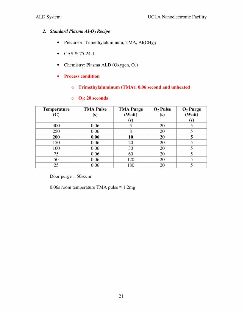
2. Standard Plasma Al2O3 Recipe
• Precursor: Trimethylaluminum, TMA, Al(CH3)3
• CAS #: 75-24-1
• Chemistry: Plasma ALD (Oxygen, O2)
• Process condition
o Trimethylaluminum (TMA): 0.06 second and unheated
o O2: 20 seconds
Temperature
(C)
TMA Pulse
(s)
TMA Purge
(Wait)
(s)
O2 Pulse
(s)
O2 Purge
(Wait)
(s)
300 0.06 5 20 5 250 0.06 8 20 5 200 0.06 10 20 5
150 0.06 20 20 5 100 0.06 30 20 5 75 0.06 60 20 5 50 0.06 120 20 5 25 0.06 180 20 5
Door purge = 50sccm
0.06s room temperature TMA pulse ≈ 1.2mg
ALD System UCLA Nanoelectronic Facility
22
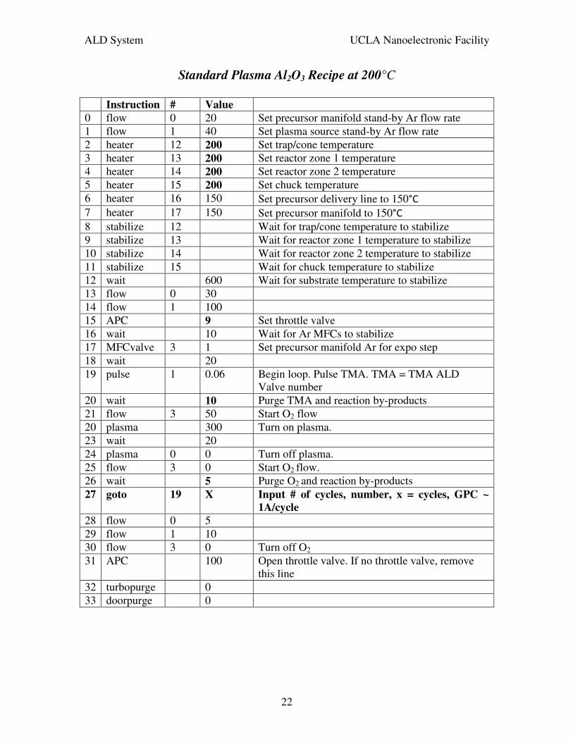
Standard Plasma Al2O3 Recipe at 200°C
Instruction # Value 0 flow 0 20 Set precursor manifold stand-by Ar flow rate 1 flow 1 40 Set plasma source stand-by Ar flow rate 2 heater 12 200 Set trap/cone temperature 3 heater 13 200 Set reactor zone 1 temperature 4 heater 14 200 Set reactor zone 2 temperature 5 heater 15 200 Set chuck temperature 6 heater 16 150 Set precursor delivery line to 150°C 7 heater 17 150 Set precursor manifold to 150°C 8 stabilize 12 Wait for trap/cone temperature to stabilize 9 stabilize 13 Wait for reactor zone 1 temperature to stabilize 10 stabilize 14 Wait for reactor zone 2 temperature to stabilize 11 stabilize 15 Wait for chuck temperature to stabilize 12 wait 600 Wait for substrate temperature to stabilize 13 flow 0 30 14 flow 1 100 15 APC 9 Set throttle valve 16 wait 10 Wait for Ar MFCs to stabilize 17 MFCvalve 3 1 Set precursor manifold Ar for expo step 18 wait 20 19 pulse 1 0.06 Begin loop. Pulse TMA. TMA = TMA ALD
Valve number 20 wait 10 Purge TMA and reaction by-products 21 flow 3 50 Start O2 flow 20 plasma 300 Turn on plasma. 23 wait 20 24 plasma 0 0 Turn off plasma. 25 flow 3 0 Start O2 flow. 26 wait 5 Purge O2 and reaction by-products 27 goto 19 X Input # of cycles, number, x = cycles, GPC ~
1A/cycle
28 flow 0 5 29 flow 1 10 30 flow 3 0 Turn off O2 31 APC 100 Open throttle valve. If no throttle valve, remove
this line 32 turbopurge 0 33 doorpurge 0
ALD System UCLA Nanoelectronic Facility
23
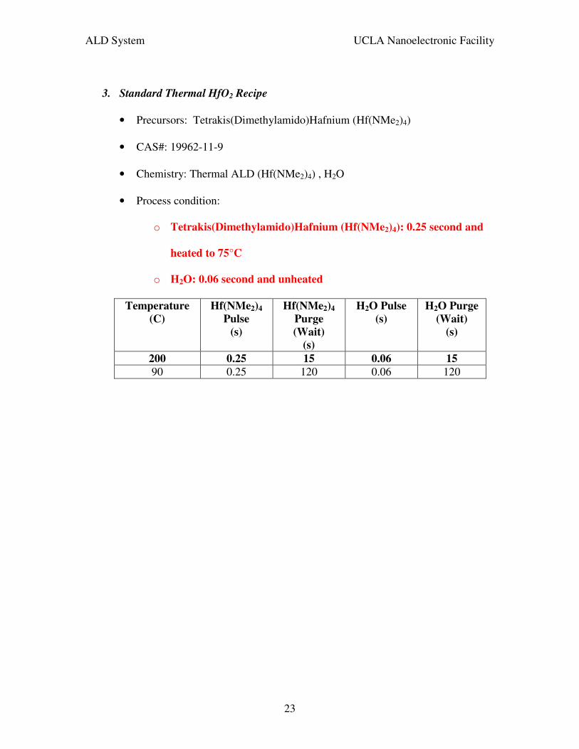
3. Standard Thermal HfO2 Recipe
• Precursors: Tetrakis(Dimethylamido)Hafnium (Hf(NMe2)4)
• CAS#: 19962-11-9
• Chemistry: Thermal ALD (Hf(NMe2)4) , H2O
• Process condition:
o Tetrakis(Dimethylamido)Hafnium (Hf(NMe2)4): 0.25 second and
heated to 75°C
o H2O: 0.06 second and unheated
Temperature
(C)
Hf(NMe2)4
Pulse
(s)
Hf(NMe2)4
Purge
(Wait)
(s)
H2O Pulse
(s)
H2O Purge
(Wait)
(s)
200 0.25 15 0.06 15
90 0.25 120 0.06 120
ALD System UCLA Nanoelectronic Facility
24
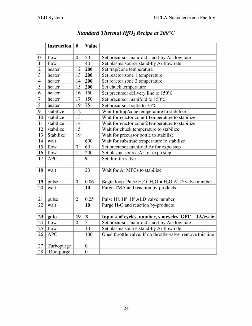
Standard Thermal HfO2 Recipe at 200°C
Instruction # Value
0 flow 0 20 Set precursor manifold stand-by Ar flow rate 1 flow 1 40 Set plasma source stand-by Ar flow rate 2 heater 12 200 Set trap/cone temperature 3 heater 13 200 Set reactor zone 1 temperature 4 heater 14 200 Set reactor zone 2 temperature 5 heater 15 200 Set chuck temperature 6 heater 16 150 Set precursor delivery line to 150°C 7 heater 17 150 Set precursor manifold to 150°C 8 heater 19 75 Set precursor bottle to 75°C 9 stabilize 12 Wait for trap/cone temperature to stabilize 10 stabilize 13 Wait for reactor zone 1 temperature to stabilize 11 stabilize 14 Wait for reactor zone 2 temperature to stabilize 12 stabilize 15 Wait for chuck temperature to stabilize 13 Stabilize 19 Wait for precursor bottle to stabilize 14 wait 600 Wait for substrate temperature to stabilize 15 flow 0 60 Set precursor manifold Ar for expo step 16 flow 1 200 Set plasma source Ar for expo step 17 APC 9 Set throttle valve.
18 wait 20 Wait for Ar MFCs to stabilize
19 pulse 0 0.06 Begin loop. Pulse H2O. H2O = H2O ALD valve number 20 wait 10 Purge TMA and reaction by-products
21 pulse 2 0.25 Pulse Hf. Hf=Hf ALD valve number 22 wait 10 Purge H2O and reaction by-products
23 goto 19 X Input # of cycles, number, x = cycles, GPC ~ 1A/cycle
24 flow 0 5 Set precursor manifold stand-by Ar flow rate 25 flow 1 10 Set plasma source stand-by Ar flow rate 26 APC 100 Open throttle valve. If no throttle valve, remove this line
27 Turbopurge 0 28 Doorpurge 0
ALD System UCLA Nanoelectronic Facility
25
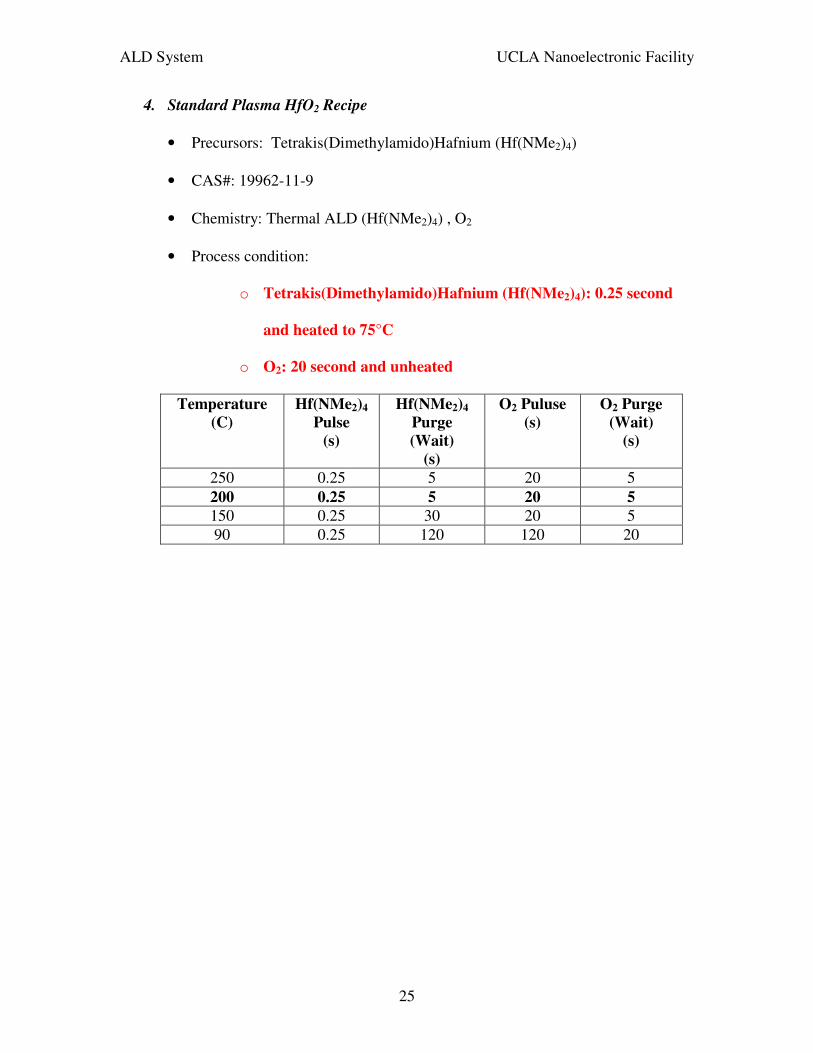
4. Standard Plasma HfO2 Recipe
• Precursors: Tetrakis(Dimethylamido)Hafnium (Hf(NMe2)4)
• CAS#: 19962-11-9
• Chemistry: Thermal ALD (Hf(NMe2)4) , O2
• Process condition:
o Tetrakis(Dimethylamido)Hafnium (Hf(NMe2)4): 0.25 second
and heated to 75°C
o O2: 20 second and unheated
Temperature
(C)
Hf(NMe2)4
Pulse
(s)
Hf(NMe2)4
Purge
(Wait)
(s)
O2 Puluse
(s)
O2 Purge
(Wait)
(s)
250 0.25 5 20 5 200 0.25 5 20 5
150 0.25 30 20 5 90 0.25 120 120 20

ALD System UCLA Nanoelectronic Facility
26
Standard Plasma HfO2 Recipe at 200°C
Instruction # Value 0 flow 0 20 Set precursor manifold stand-by Ar flow rate 1 flow 1 40 Set plasma source stand-by Ar flow rate 2 heater 12 200 Set trap/cone temperature 3 heater 13 200 Set reactor zone 1 temperature 4 heater 14 200 Set reactor zone 2 temperature 5 heater 15 200 Set chuck temperature 6 heater 16 150 Set precursor delivery line to 150°C 7 heater 17 150 Set precursor manifold to 150°C 8 Heater 19 75 Set precursor bottle to 75°C 9 stabilize 12 Wait for trap/cone temperature to stabilize 10 stabilize 13 Wait for reactor zone 1 temperature to stabilize 11 stabilize 14 Wait for reactor zone 2 temperature to stabilize 12 stabilize 15 Wait for chuck temperature to stabilize 13 stabilize 19 Wait for precursor bottle to stabilize 14 wait 600 Wait for substrate temperature to stabilize 15 MFCvalve 3 1 Set precursor manifold Ar for expo step 16 flow 0 60 17 flow 1 200 18 APC 9 Set throttle valve 19 wait 20 Wait for Ar MFCs to stabilize 20 pulse 2 0.25 Begin loop. Pulse Hf. Hf = Hf ALD Valve number 21 wait 5 Purge Hf and reaction by-products 22 flow 3 20 Start O2 flow 23 wait 5 24 plasma 300 Turn on plasma. 25 wait 20 26 plasma 0 0 Turn off plasma. 27 flow 3 0 Start O2 flow. 28 wait 5 Purge O2 and reaction by-products 29 goto 19 X Input # of cycles, number, x = cycles, GPC ~
1A/cycle
30 flow 0 5 31 flow 1 10 32 flow 3 0 Turn off O2 33 APC 100 Open throttle valve. If no throttle valve, remove
this line 34 turbopurge 0 35 doorpurge 0