file repository (fr) cell - i2b2 · i2b2 software architecture file repository (fr) cell. ... 15 3...
TRANSCRIPT

Document Version: 1.7.08-004
i2b2 Software Version: 1.7.08
Informatics for Integrating Biology and the Bedside
i2b2 Software Architecture
File Repository (FR) Cell

Partners HealthCare | Table of Contents 2

Partners HealthCare | Table of Contents 3
TABLE OF CONTENTS
DOCUMENT MANAGEMENT .................................................................................................................................. 4
ABSTRACT .............................................................................................................................................................. 5
1 OVERVIEW ..................................................................................................................................................... 6
1.1 FR DEFINITIONS, ACRONYMS AND ABBREVIATIONS .................................................................................................. 6 1.1.1 Patient Data Object (PDO) ....................................................................................................................... 6 1.1.2 Scheme ..................................................................................................................................................... 6
1.2 ROLES ............................................................................................................................................................. 6 1.3 SECURITY ......................................................................................................................................................... 6 1.4 SCOPE OF THE SYSTEM ........................................................................................................................................ 7 1.5 ASSUMPTIONS / CONSTRAINTS ............................................................................................................................ 7 1.6 TECHNICAL PLATFORM ....................................................................................................................................... 7
1.6.1 Transaction .............................................................................................................................................. 8 1.6.2 Security .................................................................................................................................................... 8 1.6.3 Persistence ............................................................................................................................................... 8 1.6.4 Reliability / Availability ............................................................................................................................ 8 1.6.5 Performance ............................................................................................................................................ 8
2 USE CASE ....................................................................................................................................................... 9
2.1 USE CASE 1...................................................................................................................................................... 9 2.2 USE CASE 2.................................................................................................................................................... 14 2.3 OPERATIONS .................................................................................................................................................. 15
3 ARCHITECTURE DESCRIPTION ...................................................................................................................... 16
3.1 COMPONENTS AND CONNECTOR VIEW ................................................................................................................ 16 3.1.1 Client-Server Style .................................................................................................................................. 16
3.1.1.1 Primary Presentation .................................................................................................................................... 17 3.1.1.2 Element Catalog ............................................................................................................................................ 17 3.1.1.3 Design Rationale, Constraints ....................................................................................................................... 18
3.2 MODULE VIEW TYPE ........................................................................................................................................ 18 3.2.1 Decomposition Style............................................................................................................................... 19
3.2.1.1 Primary Presentation .................................................................................................................................... 19 3.2.1.2 Element Catalog ............................................................................................................................................ 19 3.2.1.3 Context Diagram ........................................................................................................................................... 19
3.2.2 Uses Style ............................................................................................................................................... 20 3.2.2.1 Primary Presentation .................................................................................................................................... 20 3.2.2.2 Element Catalog ............................................................................................................................................ 20 3.2.2.3 Context Diagram ........................................................................................................................................... 20 3.2.2.4 Sequence Diagram ........................................................................................................................................ 21
3.3 MAPPINGS OF STYLES ...................................................................................................................................... 22
4 DEPLOYMENT VIEW ..................................................................................................................................... 23
4.1 GLOBAL OVERVIEW ......................................................................................................................................... 23 4.2 DETAILED DEPLOYMENT MODEL ........................................................................................................................ 24
REFERENCES ......................................................................................................................................................... 25
Partners HealthCare | Document Management 4
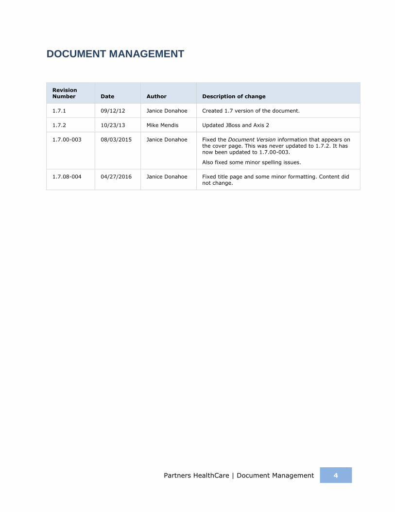
DOCUMENT MANAGEMENT
Revision Number Date Author Description of change
1.7.1 09/12/12 Janice Donahoe Created 1.7 version of the document.
1.7.2 10/23/13 Mike Mendis Updated JBoss and Axis 2
1.7.00-003 08/03/2015 Janice Donahoe Fixed the Document Version information that appears on the cover page. This was never updated to 1.7.2. It has now been updated to 1.7.00-003.
Also fixed some minor spelling issues.
1.7.08-004 04/27/2016 Janice Donahoe Fixed title page and some minor formatting. Content did not change.
Partners HealthCare | Abstract 5
ABSTRACT
This is a software architecture document for the File Repository (FR) cell. It identifies and explains the important architectural elements. This document will serve the needs of stake holders to understand the system concepts and give a brief summary of the use of the FR message format.

Partners HealthCare | Overview 6
1 OVERVIEW
The File Repository cell (FRC) is an i2b2 Hive Core cell. This cell manages i2b2 files between cells and within i2b2 applications such as the i2b2 Workbench. Under most conditions users will use the REST / SOAP service calls to access files on the FRC. In the rare conditions where users will need to have more direct access, an administrator of the server will need to create an account on the server with the same username and password as the one in the Project Management (PM) cell. At this point the user can use the File Viewer in the workbench to access the server with FTP, SFTP or a third-party client.
1.1 FR Definitions, Acronyms and Abbreviations
1.1.1 Patient Data Object (PDO)
This object mirrors the star schema database model of the data mart. It holds patient information such as clinical observations, demographics and provider data.
1.1.2 Scheme
Each distinct vocabulary and their associated codes are called a scheme. A distinction is made between codes from different sources by pre-pending a unique prefix to each code.
1.2 Roles
The primary roles / participants in the FR system are as follows:
Admin / Manager – upload and download files provided they have an account on the Project Manager server.
1.3 Security
Users can access the FR with user-id and password combination, which is authorized through the Project Management Cell. The implementation detail of the Project Management Cell is considered out-of-scope to this system context.
Additional Resources
Further details about the implementation of the Project Management Cell can be found in the following documents:

Partners HealthCare | Overview 7
Project_Management_Architecture
Project_Management_Design
Project_Management_Messaging
i2b2 Installation Guide
1.4 Scope of the system
Some other participants, currently outside the scope of the CRC are:
Project Management Cell
CRC Cell
1.5 Assumptions / Constraints
Large files over 1 GB should try to use the direct connection method.
1.6 Technical Platform
The product is designed to run on the following platform:
Java 2 Standard Edition 7.0
Oracle Server 10g/11g database
SQL Server 2005/2008
Xerces2 XML parser
Jboss Application server version 7.1.1
Spring Web Framework 2.0
Axis2 1.6.2 web service (SOAP / REST)

Partners HealthCare | Overview 8
1.6.1 Transaction
The FR system is transactional, leveraging the transaction management model of the J2EE platform.
1.6.2 Security
The application must implement basic security behaviors:
Category Behavior
Authentication Authenticate using at least a user name and a password.
Authorization User may only access categories that they are allowed to by role.
Confidentiality Sensitive data must be encrypted.
Data Integrity Data sent across the network cannot be modified by a tier.
Auditing In the later releases we may implement logging of sensitive actions.
1.6.3 Persistence
This application utilizes JDBC calls to retrieve persisted data.
1.6.4 Reliability / Availability
The reliability / availability will be addressed through the J2EE platform
Targeted availability is 16 / 7: 16 hours a day, 7 days a week
The remaining time (8 hours) is reserved for any maintenance activities
1.6.5 Performance
The user authentication with the project management cell must be under 1 second.

Partners HealthCare | Use Case 9
2 USE CASE
The diagram below depicts common use cases a user may perform with the FR cell.
2.1 Use Case 1
Client:
Assumes:
Patient ID is in the database
Encounter ID is in the database
Action:
Batch Tab:
Step 1:
1. Allow end user to get sample csv file.
Step 2:
1. Allow end user to upload filled in csv file
2. Convert CSV to PDO containing Patients, Observation, MRN Mapping, Visit Mapping or Visits.
3. Validate CSV data contains numbers in number fields, dates in date fields, the not null columns have data and files exist on local client, this is done with a wizard.
4. If the CSV file has a value in the FileName column, then set the valType to a “F”, convert tval in ObservationType to a (/ [Project ID] / [Core Cell] / [Destination]) C Where Project ID is the ID of the current Project such as Demo or Asthma, Core Cell is the ID of the cell which the file is related to, such as CRC, Destination is the remote directory and filename to place the local file which is gotten from the CSV file.

Partners HealthCare | Use Case 10
Step 3:
1. Send a web service call to the Data Repository Uploader, with PDO XML object as a SOAP attachment.
<message_body>
<request_header>
<request_type>Data_Load</request_type>
</request_header>
<request>
<input_option>
<data_file location_uri="irods://irods_url" type="PDO"
source_system_cd="MGHDIAGS"
upload_label="MGHDIAGS"/>
</input_option>
<load_option commit_flag="true" delete_staging="true">
<load_observation_set append_flag="false"/>
<load_event_set />
<load_patient_set />
<load_observer_set />
<load_concept_set />
</load_option>
<output_option summary="true">
<event_set onlykeys="" status="" blob="" techdata=""/>
<observation_set />
<patient_set />
<observer_set />
<concept_set />
</output_option>
</request>
</message_body>
With Location_uri, Source_system_cd, Upload_label unique, the rest of the <message_body> will be the same as above.
The response of an error will be reported to the user; a successful start will not be reported. The user can see status on the “status” tab.
The server will take the file and send it to the File Repository via SFTP. The destination will be:
/ [PROJECT ID] / CRC / [Destination Dir and File]
It will then buffer read the file and insert the records into the CRC database.

Partners HealthCare | Use Case 11
Status Tab:
1. Display status of all current and past loads for the specific user.
2. Send Web Service Call to Data Repository cell to get loads.
<message_body>
<request_header>
<request_type>Get_Load_Status</request_type>
</request_header>

Partners HealthCare | Use Case 12
<request>
<user_id />
<load_id />
</request>
The USER_ID will be the current user and the response will be:
<response>
<status load_id="100">
<upload_label/>
<user_id/>
<source_cd/>
<loaded_record/>
<load_date/>
<load_status/>
<message/>
<input_file_name/>
<log_file_name/>
<transform_name/>
<deleted_record/>
</status>
</response>
The client will parse the response and populate the table

Partners HealthCare | Use Case 13
Server:
Create 4 web services; the first 2 are part of the CRC Loader, while the last 2 are part of the File Repository.
1. Display status of current and past loads for a specific user.
2. Load a set of observations from the PDO file on the File Repository into the Data Repository. The URI send will contain the location of the PDO file, the format of the SRB URI is (srb:// [ username . domainHome @ ] host [ : port ] [ / path]. The file will be downloaded by using the URI, storage broker, and the password / token from the message header. The storage resource can be retrieved from the PM cell, under the parameters name of “SRBDefaultStorageResource”. All the PDO objects will be loaded into the database directly without encrypting or mapping the patient or encounter id. Use case 2 will deal with preprocessing the database.
3. Create a Web Service which will be able to download a File.

Partners HealthCare | Use Case 14
4. Create a Web Service with will be able to Upload a File.
2.2 Use Case 2
Allow end users direct access to the FR cell. An administrator of the server will need to create an account on the server with the same username and password as the one in the Project Management cell. At this point the user can use the File Viewer in the workbench to access the server with FTP, SFTP or a third-party client. Users will be able to remove files / directories, add files / directories, rename, and also upload / download files, using a friendly UI interface built into the workbench.
Partners HealthCare | Use Case 15
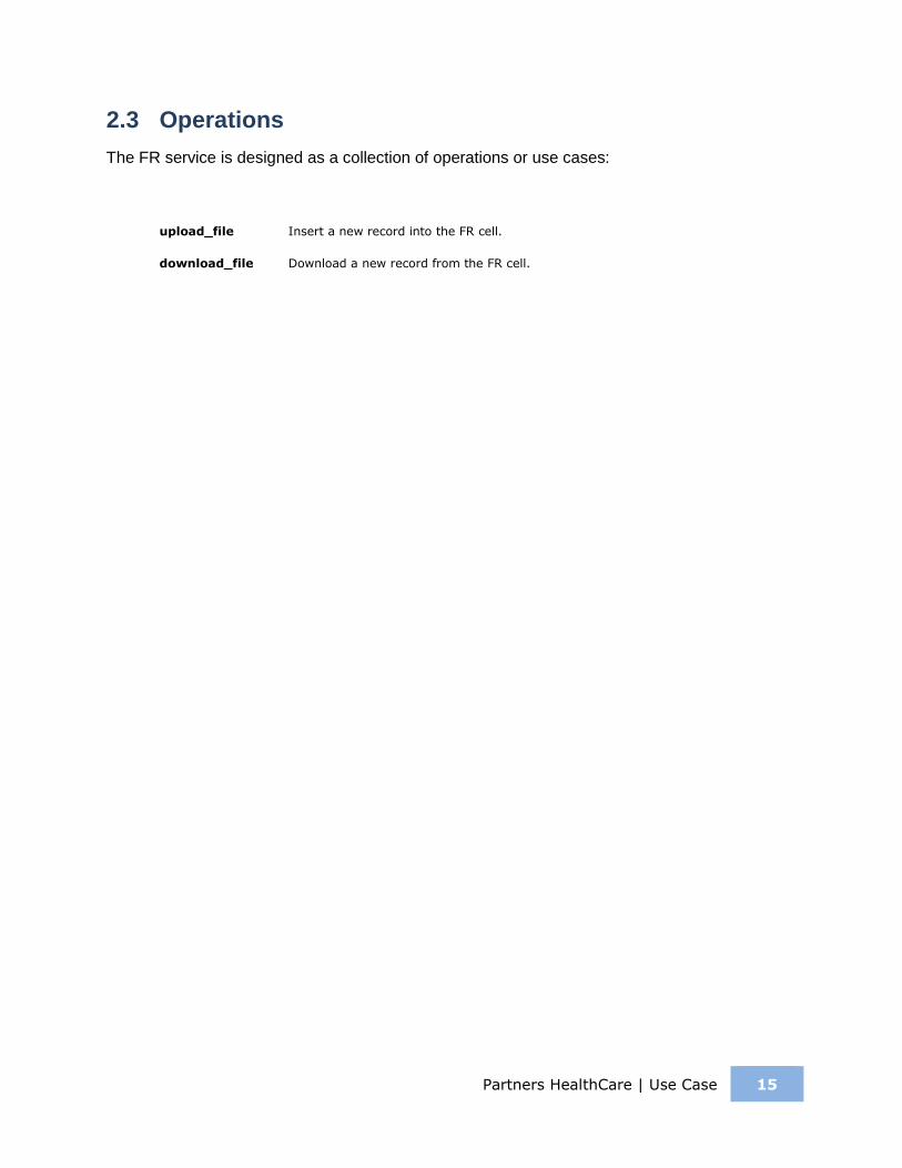
2.3 Operations
The FR service is designed as a collection of operations or use cases:
upload_file Insert a new record into the FR cell.
download_file Download a new record from the FR cell.

Partners HealthCare | Architecture Description 16
3 ARCHITECTURE DESCRIPTION
This section provides a description of the architecture as multiple views. Each view conveys the different attributes of the architecture.
1. Components and Connector View
a. Client-Server Style
2. Module View
a. Decomposition Style
b. Uses Style
3. Data View
4. Deployment View
3.1 Components and Connector View
A Component and Connector view (C&C) represents the runtime instances and the protocols of connection between the instances. The connectors represent the properties such as concurrency, protocols and information flows. The diagram shown in the Primary Presentation section represents the Component and Connector view for the multi-user installation. As seen in the diagram, component instances are shown in more detail with specific connectors drawn in different notations.
3.1.1 Client-Server Style
The FR system is represented using the components and connector client-server view.

Partners HealthCare | Architecture Description 17
3.1.1.1 Primary Presentation
3.1.1.2 Element Catalog
Element Name Type Description
i2b2 Workbench Client Component Webservice client submits the request to the FR Server components and renders a response XML.
File Repository Server Server Component Provides a socket interface for the FR system. It supports the REST protocol.
It uses the Project Management server to handle user authentication.
CRC Server Server Provides Web Service Interface for the CRC system. It supports both SOAP and REST protocols.
It uses Project Management server to handle user authentication.
It uses Ontology server to lookup the concepts

Partners HealthCare | Architecture Description 18
Element Name Type Description
metadata.
It stores Setfinder query definition, query run instance and the corresponding query results. The user can then request Patient Data Object using the Setfinder results.
Project Management Server Server Component FR cell uses the Project Management cell to authenticate the user.
FR cell constructs the PM request message and makes a web service call to the Project Management cell.
CRC Datamart DB Data Repository This repository is mainly a data mart for patient’s clinical observation information represented in star schema.
This database also holds CRC user queries (setfinder query) information and its results like patient sets, visit set etc.
JDBC Query Connector SQL query used as a connector between the FR System and the Metadata database.
Web Service Request Connector REST protocol used to communicate with the external system.
3.1.1.3 Design Rationale, Constraints
N-tier Architecture
The client-server style depicts an n-tier architecture that separates the presentation layer from the business logic and data access layer.
3.2 Module View Type
The module view shows how the system is decomposed into implementation units and how the functionality is allocated to these units. The layers show how modules are encapsulated and structured. The layers represent the “allowed-to-use” relation.
The following sections describe the module view using Decomposition and Uses Styles.

Partners HealthCare | Architecture Description 19
3.2.1 Decomposition Style
The Decomposition style presents system functionality in terms of manageable work pieces. It identifies modules and breaks them down into sub-modules and so on, until a desired level of granularity is achieved.
3.2.1.1 Primary Presentation
System Segment
File Repository Server Operation Manager
3.2.1.2 Element Catalog
Element Name Type Description
Operation Manager Subsystem This subsystem manages queries for FR operations.
3.2.1.3 Context Diagram

Partners HealthCare | Architecture Description 20
3.2.2 Uses Style
The Uses style shows the relationship between modules and sub-modules. This view is very helpful for implementing, integrating and testing the system.
3.2.2.1 Primary Presentation
System Segment
File Repository Server FR Module
Operation Manager Subsystem FR Fileservice
3.2.2.2 Element Catalog
Element Name Type Description
FR Module Module Authenticates the user through the PM Server System.
FR Fileservice Communication Module Provides file service interface to FR operations.
3.2.2.3 Context Diagram

Partners HealthCare | Architecture Description 21
3.2.2.4 Sequence Diagram

Partners HealthCare | Architecture Description 22
3.3 Mappings of Styles
The following table is a mapping between the elements in the Component & Connector Client-Server view shown in section 3.1.1, and the Modules Uses view and Decomposition view shown in sections 3.2.1 and 3.2.2.
The relationship shown is is-implemented-by, i.e. the elements from the C&C view shown at the top of the table are implemented by any selected elements from the Modules views, denoted by and “X” in the corresponding cell.
FR Server Project Management
Server Metadata Database
FR Service X X
Request Handler X
Request DAO X X
Vocabulary Data Object X

Partners HealthCare | Deployment View 23
4 DEPLOYMENT VIEW
4.1 Global Overview
Partners HealthCare | Deployment View 24
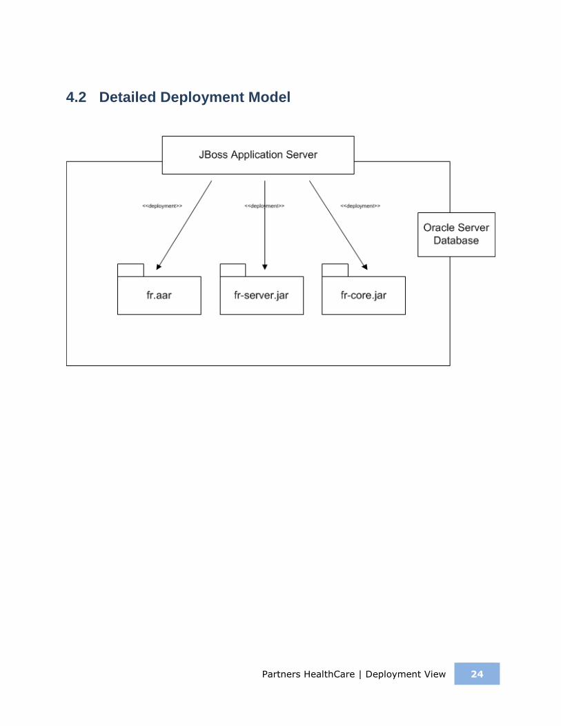
4.2 Detailed Deployment Model

Partners HealthCare | References 25
REFERENCES
i2b2 (Informatics for Integrating Biology and the Bedside) https://www.i2b2.og/resrcs/hive.html