filed by: g. scott shepherd, property development
TRANSCRIPT

Filed by: G. Scott Shepherd, Property Development Specialist II- SBA Communications
134 Flanders Rd., Suite 125, Westborough, MA 01581 508.251.0720 x 3807 - [email protected]
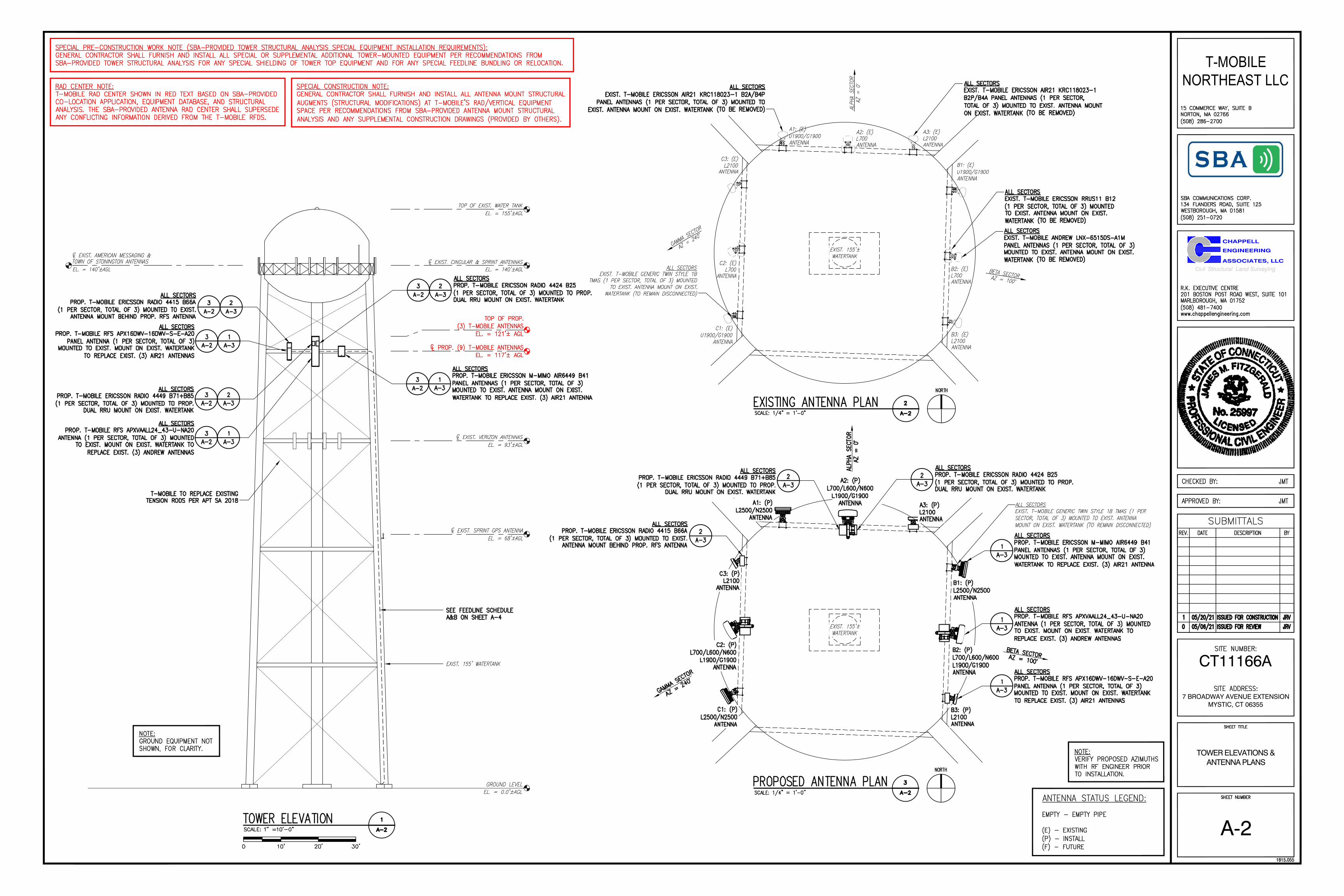
August 3, 2021 Melanie A. Bachman Acting Executive Director Connecticut Siting Council Ten Franklin Square New Britain, CT 06051 Notice of Exempt Modification 113 Broadway Extension (aka 7 Broadway Extension), Mystic, CT Latitude: 41.349536 Longitude: 71.963644 T-Mobile #: CT11166A_Anchor Dear Ms. Bachman: T-Mobile currently maintains nine (9) antennas at the 117-foot of the existing 155-foot Water Tank at 113 Broadway Extension (aka 7 Broadway Extension) in Mystic, CT. The water tank is owned by Planeta Properties and is managed by SBA Site Management (recently acquired from Message Center Management.) T-Mobile now intends to remove six (6) antennas and replace six (6) new L600/700/1900/2100MHz antennas.
• The antennas would support 5G services and would be installed at the 117-foot level of the Water Tank Planned Modifications: TOWER
Remove:
• N/A Remove and Replace:
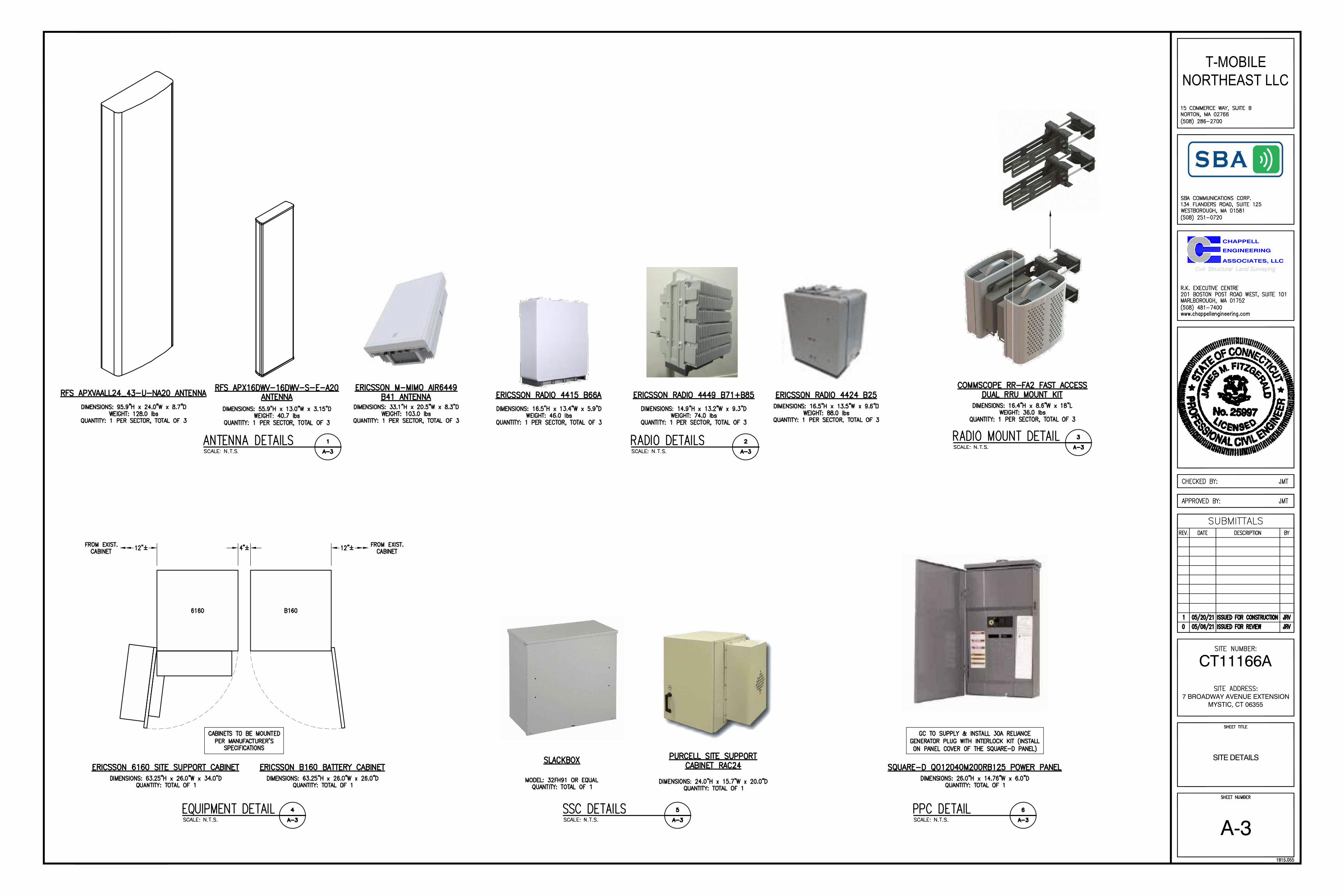
• (3) Ericsson Air21 B2A/B4P antennas (remove) – (3) Ericsson AIR6449 B41 2500MHz antennas (replace) • (3) Ericsson Air21 B4A/B2P antennas (remove) – (3) RFS APXVAALL24-43-U-NA20 600/700/1900MHz
antennas (replace) • (3) Commscope LNX-6515DS-VTM antennas (remove) – (3) RFS APX16DWV-16DWVS-E-A20 2100MHz
antennas (replace) • (3) Ericsson S11B12 RRUs (replace) – (3) Ericsson 4449 B71 + B85 RRUs
Install New:
• (3) Ericsson 4415 B66A RRUs • (6) 2” HCS Fiber • (3) Ericsson 4415 RRHS
Existing Equipment to Remain:
• (3) Ericsson KRY 112/71 TMAs Entitlements):
• (3) Twin TMAs • (12) 1-5/8” coax • (3) 1-1/4” fiber
GROUND
Remove:
• Nortel S8000 Equipment cabinet Remove and Replace:
• Existing power panel (remove) – Telco panel (replace) as required Install New:
• 100A AC Service to be upgraded • Purcell RAC24 cabinet to proposed Unistrut • (8) 2” RGS conduit • (1) 1” RGS conduit • 200A AC serice to existing Unistrut • Slackbox • Ericsson B160 Battery cabinet • Ericsson 6161 Equipment cabinet
Existing Equipment to Remain:
• (1) 1/2” coax (for GPS) • (1) 10’ x 8’ Concrete Pad • Ice Shield • (1) RBS6131 Equipment cabinet
This facility was originally approved prior to the Council’s jurisdiction. On September 2, 1999, the Town of
Stonington’s Planning and Zoning Commission approved application #PZ9954SPA under Site Plan Approval for the installation of antennas on an existing water tank and the placement of equipment shelter. The only stipulation set was that noise be measured after installation of the tower to assure town zoning compliance. There were no other post construction stipulations set. Please see attached.
Please accept this letter as notification pursuant to Regulations of Connecticut State Agencies §16-50j-73,
for construction that constitutes an exempt modification pursuant to R.C.S.A. §16.50j-72(b)(2). In accordance with R.C.S.A. § 16.50j-73, a copy of this letter is being sent to the Town of Stonington’s First Selectman, Robert Simmons, and Zoning Enforcement Officer, Candace Palmer, as well as to the property owner, Planeta Properties. (Separate notice is not being sent to tower owner, as it belongs to SBA.)
The planned modifications to the facility fall squarely within those activities explicitly provided for in R.C.S.A. §16.50j-72(b)(2).
1. The proposed modifications will not result in an increase in the height of the existing structure. 2. The proposed modification will not require the extension of the site boundary. 3. The proposed modifications will not increase noise levels at the facility by six decibels or more, or to levels
that exceed state and local criteria. 4. The operation of the replacement antennas will not increase radio frequency emissions at the facility to a level
at or above the Federal Communications Commission safety standard. 5. The proposed modification will not cause a change or alteration in the physical or environmental
characteristics of the site. 6. The existing structure and its foundation can support the proposed loading.
For the foregoing reasons, T-Mobile respectfully submits that the proposed modifications to the above-referenced telecommunication facility constitute an exempt modifications under R.C.S.A. § 16-50j-72(b)(2).
Sincerely, G. Scott Shepherd Property Development Specialist II SBA COMMUNICATIONS CORPORATION 134 Flanders Rd., Suite 125 Westborough, MA 01581 508.251.0720 x3807 + T 508.366.2610 + F 508.868.6000 + C [email protected] Attachments cc: Danielle Chesebrough, First Selectman / with attachments Town of Stonington, 152 Elm Street, Stonington, CT 06378 Keith Brynes, Planning & Zoning Commission / with attachments Town of Stonington, 152 Elm Street, Stonington, CT 06378 Planeta Properties c/o Edward Planeta / with attachments
4343 Corso Venetia Blvd., Venice FL 34293 (SBA Address on File) 7 Broadway Avenue Extension, Mystic, CT 06355 (Town Address on File)

EXHIBIT LIST
Exhibit 1 Check Copy x Exhibit 2 Notification Receipts x Exhibit 3 Property Card x Exhibit 4 Property Map x Exhibit 5 Original Zoning Approval Town of Stonington P&Z 9/2/99 Exhibit 6 Construction Drawings Chappell Engineering 5/20/21 Exhibit 7 Structural Analysis All Points Technology 5/10/21 Exhibit 8 EME Report EBI Consulting 6/9/21

EXHIBIT 1

EXHIBIT 2

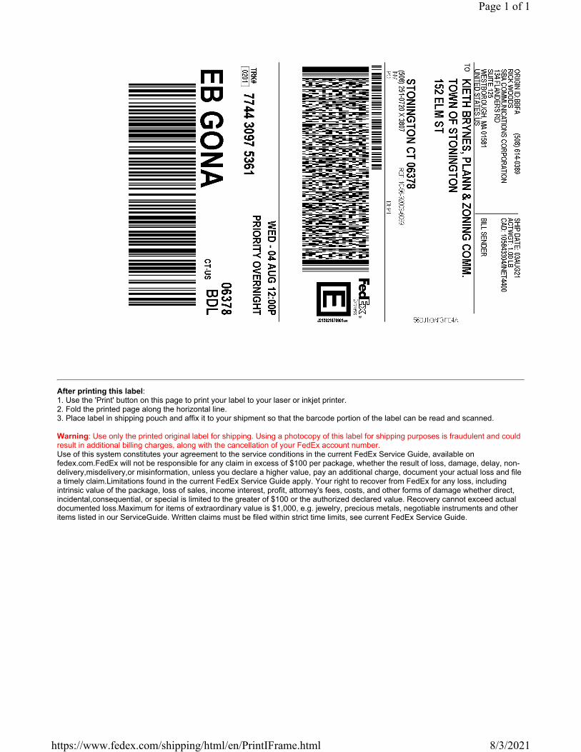
After printing this label:1. Use the 'Print' button on this page to print your label to your laser or inkjet printer.2. Fold the printed page along the horizontal line.3. Place label in shipping pouch and affix it to your shipment so that the barcode portion of the label can be read and scanned.
Warning: Use only the printed original label for shipping. Using a photocopy of this label for shipping purposes is fraudulent and could result in additional billing charges, along with the cancellation of your FedEx account number. Use of this system constitutes your agreement to the service conditions in the current FedEx Service Guide, available on fedex.com.FedEx will not be responsible for any claim in excess of $100 per package, whether the result of loss, damage, delay, non-delivery,misdelivery,or misinformation, unless you declare a higher value, pay an additional charge, document your actual loss and file a timely claim.Limitations found in the current FedEx Service Guide apply. Your right to recover from FedEx for any loss, including intrinsic value of the package, loss of sales, income interest, profit, attorney's fees, costs, and other forms of damage whether direct, incidental,consequential, or special is limited to the greater of $100 or the authorized declared value. Recovery cannot exceed actual documented loss.Maximum for items of extraordinary value is $1,000, e.g. jewelry, precious metals, negotiable instruments and other items listed in our ServiceGuide. Written claims must be filed within strict time limits, see current FedEx Service Guide.
Page 1 of 1
8/3/2021https://www.fedex.com/shipping/html/en/PrintIFrame.html

FROM
SBA COMMUNICATIONS CORPORATIONRick Woods
134 Flanders RdSuite 125
WESTBOROUGH, MA US 01581508-614-0389
TO
Melanie A. Bachman Exec. DirConnecticut Siting Council
Ten Franklin SquareNEW BRITAIN, CT US 06051
508-251-0720
TRACK ANOTHER SHIPMENT
774430873171
ADD NICKNAME
Scheduled delivery: Thursday, August 5, 2021 before 10:30 am
PICKED UP
FRAMINGHAM, MA
GET STATUS UPDATES
Travel History
Wednesday, August 4, 2021
12:37 PM FRAMINGHAM, MA Picked up
Tuesday, August 3, 2021
10:48 AM Shipment information sent to FedEx
Shipment Facts
TRACKING NUMBER
774430873171
SERVICE
FedEx Priority Overnight
WEIGHT
2 lbs / 0.91 kgs
TOTAL PIECES
1
TOTAL SHIPMENT WEIGHT
2 lbs / 0.91 kgs
TERMS
Shipper
SHIPPER REFERENCE
10-56-92009-6089
PACKAGING
FedEx Pak
SPECIAL HANDLING SECTION
Deliver Weekday
MANAGE DELIVERY
Local Scan TimeTIME ZONE
Page 1 of 2Detailed Tracking
8/4/2021https://www.fedex.com/fedextrack/?trknbr=774430873171&trkqual=2459430000~7744308...

After printing this label:1. Use the 'Print' button on this page to print your label to your laser or inkjet printer.2. Fold the printed page along the horizontal line.3. Place label in shipping pouch and affix it to your shipment so that the barcode portion of the label can be read and scanned.
Warning: Use only the printed original label for shipping. Using a photocopy of this label for shipping purposes is fraudulent and could result in additional billing charges, along with the cancellation of your FedEx account number. Use of this system constitutes your agreement to the service conditions in the current FedEx Service Guide, available on fedex.com.FedEx will not be responsible for any claim in excess of $100 per package, whether the result of loss, damage, delay, non-delivery,misdelivery,or misinformation, unless you declare a higher value, pay an additional charge, document your actual loss and file a timely claim.Limitations found in the current FedEx Service Guide apply. Your right to recover from FedEx for any loss, including intrinsic value of the package, loss of sales, income interest, profit, attorney's fees, costs, and other forms of damage whether direct, incidental,consequential, or special is limited to the greater of $100 or the authorized declared value. Recovery cannot exceed actual documented loss.Maximum for items of extraordinary value is $1,000, e.g. jewelry, precious metals, negotiable instruments and other items listed in our ServiceGuide. Written claims must be filed within strict time limits, see current FedEx Service Guide.
Page 1 of 1
8/3/2021https://www.fedex.com/shipping/html/en/PrintIFrame.html

FROM
SBA COMMUNICATIONS CORPORATIONRick Woods
134 Flanders RdSuite 125
WESTBOROUGH, MA US 01581508-614-0389
TO
Danielle Chesebrough, First SelectmTown of Stonington
152 Elm StSTONINGTON, CT US 06378
508-251-0720
TRACK ANOTHER SHIPMENT
774430936456
ADD NICKNAME
Scheduled delivery: Thursday, August 5, 2021 before 12:00 pm
PICKED UP
FRAMINGHAM, MA
GET STATUS UPDATES
Travel History
Wednesday, August 4, 2021
12:37 PM FRAMINGHAM, MA Picked up
Tuesday, August 3, 2021
10:51 AM Shipment information sent to FedEx
Shipment Facts
TRACKING NUMBER
774430936456
SERVICE
FedEx Priority Overnight
WEIGHT
0.5 lbs / 0.23 kgs
TOTAL PIECES
1
TOTAL SHIPMENT WEIGHT
0.5 lbs / 0.23 kgs
TERMS
Shipper
SHIPPER REFERENCE
10-56-92009-6089
PACKAGING
FedEx Envelope
SPECIAL HANDLING SECTION
Deliver Weekday
MANAGE DELIVERY
Local Scan TimeTIME ZONE
Page 1 of 2Detailed Tracking
8/4/2021https://www.fedex.com/fedextrack/?trknbr=774430936456&trkqual=2459430000~7744309...
After printing this label:1. Use the 'Print' button on this page to print your label to your laser or inkjet printer.2. Fold the printed page along the horizontal line.3. Place label in shipping pouch and affix it to your shipment so that the barcode portion of the label can be read and scanned.
Warning: Use only the printed original label for shipping. Using a photocopy of this label for shipping purposes is fraudulent and could result in additional billing charges, along with the cancellation of your FedEx account number. Use of this system constitutes your agreement to the service conditions in the current FedEx Service Guide, available on fedex.com.FedEx will not be responsible for any claim in excess of $100 per package, whether the result of loss, damage, delay, non-delivery,misdelivery,or misinformation, unless you declare a higher value, pay an additional charge, document your actual loss and file a timely claim.Limitations found in the current FedEx Service Guide apply. Your right to recover from FedEx for any loss, including intrinsic value of the package, loss of sales, income interest, profit, attorney's fees, costs, and other forms of damage whether direct, incidental,consequential, or special is limited to the greater of $100 or the authorized declared value. Recovery cannot exceed actual documented loss.Maximum for items of extraordinary value is $1,000, e.g. jewelry, precious metals, negotiable instruments and other items listed in our ServiceGuide. Written claims must be filed within strict time limits, see current FedEx Service Guide.
Page 1 of 1
8/3/2021https://www.fedex.com/shipping/html/en/PrintIFrame.html

FROM
SBA COMMUNICATIONS CORPORATIONRick Woods
134 Flanders RdSuite 125
WESTBOROUGH, MA US 01581508-614-0389
TO
Kieth Brynes, Plann & Zoning Comm.Town of Stonington
152 Elm StSTONINGTON, CT US 06378
508-251-0720
TRACK ANOTHER SHIPMENT
774430975361
ADD NICKNAME
Scheduled delivery: Thursday, August 5, 2021 before 12:00 pm
PICKED UP
FRAMINGHAM, MA
GET STATUS UPDATES
Travel History
Wednesday, August 4, 2021
12:37 PM FRAMINGHAM, MA Picked up
Tuesday, August 3, 2021
10:54 AM Shipment information sent to FedEx
Shipment Facts
TRACKING NUMBER
774430975361
SERVICE
FedEx Priority Overnight
WEIGHT
0.5 lbs / 0.23 kgs
TOTAL PIECES
1
TOTAL SHIPMENT WEIGHT
0.5 lbs / 0.23 kgs
TERMS
Shipper
SHIPPER REFERENCE
10-56-92009-6089
PACKAGING
FedEx Envelope
SPECIAL HANDLING SECTION
Deliver Weekday
MANAGE DELIVERY
Local Scan TimeTIME ZONE
Page 1 of 2Detailed Tracking
8/4/2021https://www.fedex.com/fedextrack/?trknbr=774430975361&trkqual=2459430000~7744309...

After printing this label:1. Use the 'Print' button on this page to print your label to your laser or inkjet printer.2. Fold the printed page along the horizontal line.3. Place label in shipping pouch and affix it to your shipment so that the barcode portion of the label can be read and scanned.
Warning: Use only the printed original label for shipping. Using a photocopy of this label for shipping purposes is fraudulent and could result in additional billing charges, along with the cancellation of your FedEx account number. Use of this system constitutes your agreement to the service conditions in the current FedEx Service Guide, available on fedex.com.FedEx will not be responsible for any claim in excess of $100 per package, whether the result of loss, damage, delay, non-delivery,misdelivery,or misinformation, unless you declare a higher value, pay an additional charge, document your actual loss and file a timely claim.Limitations found in the current FedEx Service Guide apply. Your right to recover from FedEx for any loss, including intrinsic value of the package, loss of sales, income interest, profit, attorney's fees, costs, and other forms of damage whether direct, incidental,consequential, or special is limited to the greater of $100 or the authorized declared value. Recovery cannot exceed actual documented loss.Maximum for items of extraordinary value is $1,000, e.g. jewelry, precious metals, negotiable instruments and other items listed in our ServiceGuide. Written claims must be filed within strict time limits, see current FedEx Service Guide.
Page 1 of 1
8/3/2021https://www.fedex.com/shipping/html/en/PrintIFrame.html

FROM
SBA COMMUNICATIONS CORPORATIONRick Woods
134 Flanders RdSuite 125
WESTBOROUGH, MA US 01581508-614-0389
TO
Edward PlanetaPlaneta Properties
4343 Corso Venetia BlvdVENICE, FL US 34293
508-251-0720
TRACK ANOTHER SHIPMENT
774431018128
ADD NICKNAME
Scheduled delivery: Thursday, August 5, 2021 before 12:00 pm
PICKED UP
FRAMINGHAM, MA
GET STATUS UPDATES
Travel History
Wednesday, August 4, 2021
12:37 PM FRAMINGHAM, MA Picked up
Tuesday, August 3, 2021
10:56 AM Shipment information sent to FedEx
Shipment Facts
TRACKING NUMBER
774431018128
SERVICE
FedEx Priority Overnight
WEIGHT
0.5 lbs / 0.23 kgs
TOTAL PIECES
1
TOTAL SHIPMENT WEIGHT
0.5 lbs / 0.23 kgs
TERMS
Shipper
SHIPPER REFERENCE
10-56-92009-6089
PACKAGING
FedEx Envelope
SPECIAL HANDLING SECTION
Deliver Weekday
MANAGE DELIVERY
Local Scan TimeTIME ZONE
Page 1 of 2Detailed Tracking
8/4/2021https://www.fedex.com/fedextrack/?trknbr=774431018128&trkqual=2459430000~7744310...

EXHIBIT 3
Kitchen Style
Land Use
Land Class
Mailing Address
Owner
Property Location
Zoning Code
Census Tract
Co-Owner
Street Index
Utilities
Acreage
Lot Setting/Desc
Survey Map #
Photo
Building Style
Bedrooms
Half Bathrooms
Building Condition
Primary Construction Details
Property Information
Report Created On
Year Built
Roof Style
Roof Cover
Sketch
Exterior Walls
Interior Walls
Interior Floors 1
Heating Type
Heating Fuel
Map Block Lot
Building Use
Full Bathrooms
Bath Style
Stories
Property Listing Report
Town of Stonington, CT
Interior Floors 2
Extra Fixtures
Exterior Walls 2
Interior Walls 2
AC Type
Total Rooms
Occupancy
Building Grade
Building Desc.
Heat / AC
Frame Type
Baths / Plumbing
Ceiling / Wall
Rooms / Prtns
First Floor Use
Wall Height
(*Industrial / Commercial Details)
AccountBuilding # Section #
School District
Fire District
Trash Day
Polling Place (District)
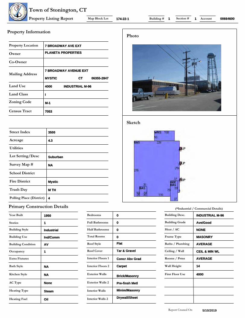
INDUSTRIAL M-96INDUSTRIAL M-96
II
7 BROADWAY AVE EXT7 BROADWAY AVE EXT
M-1M-1
7 BROADWAY AVENUE EXT7 BROADWAY AVENUE EXT
MYSTICMYSTIC CTCT 06355-284706355-2847
40004000
70537053
PLANETA PROPERTIESPLANETA PROPERTIES
35003500
SuburbanSuburban
4.34.3
NANA
MysticMystic
M THM TH
44
174-22-1174-22-1
IndustrialIndustrial
00
00
11
NANA
5/10/2019
19501950
FlatFlat
Tar & GravelTar & Gravel
Concr Abv GradConcr Abv Grad
SteamSteam
OilOil
Ind/CommInd/Comm
00
NANA
Minim/MasonryMinim/Masonry
Brick/MasonryBrick/Masonry
AVAV
CarpetCarpet
Pre-finsh MetlPre-finsh Metl
Drywall/SheetDrywall/Sheet
NoneNone
00
11
Ave/GoodAve/Good
INDUSTRIAL M-96INDUSTRIAL M-96
NONENONE
MASONRYMASONRY
AVERAGEAVERAGE
CEIL & MIN WLCEIL & MIN WL
AVERAGEAVERAGE
1414
40004000
006646000066460011 11
Sales HistorySale Date Sale PriceBook/ Page
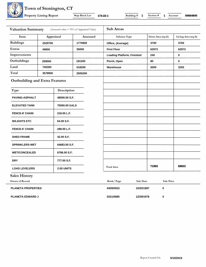
Valuation Summary
Land
Buildings
Outbuildings
Appraised Assessed
(Assessed value = 70% of Appraised Value)
Improvements
Extras
Total
Owner of Record
Report Created On
Item
Sub Areas
Subarea Type Gross Area (sq ft) Living Area (sq ft)
Total Area
Outbuilding and Extra Features
Type Description
Map Block LotProperty Listing Report
Town of Stonington, CTAccountBuilding # Section #
0
0
10/20/1997
12/29/1978
740300 518200
2529700 1770800
259000 181200
49900 35000
3578900 2505200
5/10/2019
PLANETA PROPERTIES
PLANETA EDWARD J
3700
62973
0
0
3250
Office, (Average)
First Floor
Loading Platform, Finished
Porch, Open
Warehouse
3700
62973
240
80
5000
0409/0933
0221/0680
PAVING-ASPHALT
ELEVATED TANK
FENCE-8' CHAIN
W/LIGHTS ETC
FENCE-6' CHAIN
SHED FRAME
SPRINKLERS-WET
WET/CONCEALED
DRY
LOAD LEVELERS
48000.00 S.F.
75000.00 GALS
218.00 L.F.
64.00 S.F.
288.00 L.F.
42.00 S.F.
64683.00 S.F.
6786.00 S.F.
777.00 S.F.
2.00 UNITS6992369923
174-22-1174-22-1
7199371993
006646000066460011 11

EXHIBIT 4

XXX
éééé
ééé
XXXXXXXXXXXX
XX
X
XXX
X X
XX
XXX
X
X X XX
XX
X
XXXXX
X
XX
éééé
éééé
éééX
XX
XX
XX
XX
XX
X
XX
XX
XX
X
XX
X
XX
XX
X
XX X
X
XXX
X
X
X
XX
X
XXX
X
X
!!
!!
!!
!!
!!
!!
!!
!!
!!
!!
!!
!!
!!
!!
!!
!!
!!
!!
!!
!!
!!
!!
!!
!!
!!
!!
!!
!!
!!
!!
!!
!!
!!
!!
!
2
1
9
8
7
6
5
43
2
1
2
1
2A
3
45
65433
42
7
RD1
105.
9
15416
2-D
100
50
RO
W
ROW
ROW
14' R
OW
ROOSEVELT ST
STAFFORD ST
SOLON AVE
BRO
ADW
AY E
XT
WET LAND
18A
(17
(22
(23
(15
17
27
212
17 21
2
21
1
19
2
7
4
82
7
18
4.3 AC-S
BLDG 18
687
100
131+/-
43.6
230
16.5
35
278
350-S
6545
185
62
194.2
135
51.5
90
88 65 26.454289.7
165-S
60
10752.3
52.3
180-S
23.6
400.
0
61.3
446.7
108.
8110
0.02
100.
075
7514
650
90.6
5080
117.8
273.6186.6
70
255-S
60
77.2
81.7
84 60 60 83
110
164 105
55-S
72.2
35.0
1
86.8
90-S
135
119.
94
108.
11
98.1755
104
160
125-S
140-S
106.
5
145
80.0
80.0
1
10
88.0
90 100
117.
0
210+
/-
46.5 100
65-S
10-S
15-S
50-S
41.9
106.
5
50
96.2
108.
11
175.5
15
Disclaimer: This map is for informational purposes only All information is subject to verification by any user. The Town of Stonington and its mapping
contractors assume no legal responsibility for the information contained herein.0 60 120 180 240Feet
Parcel: 174-22-1Town of Stonington, Connecticut - Assessment Parcel Map
Address: 7 BROADWAY AVE EXT
Approximate Scale: 1 inch = 100 feet8
Map Produced: April 2019Revised To: October 2018
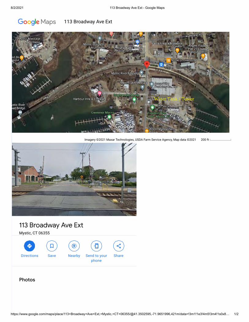
8/2/2021 113 Broadway Ave Ext - Google Maps
https://www.google.com/maps/place/113+Broadway+Ave+Ext,+Mystic,+CT+06355/@41.3502595,-71.9651996,421m/data=!3m1!1e3!4m5!3m4!1s0x8… 1/2
Imagery ©2021 Maxar Technologies, USDA Farm Service Agency, Map data ©2021 200 ft
113 Broadway Ave ExtMystic, CT 06355
Directions Save Nearby Send to yourphone
Share
Photos
113 Broadway Ave Ext
Water Tank / Tower

EXHIBIT 5
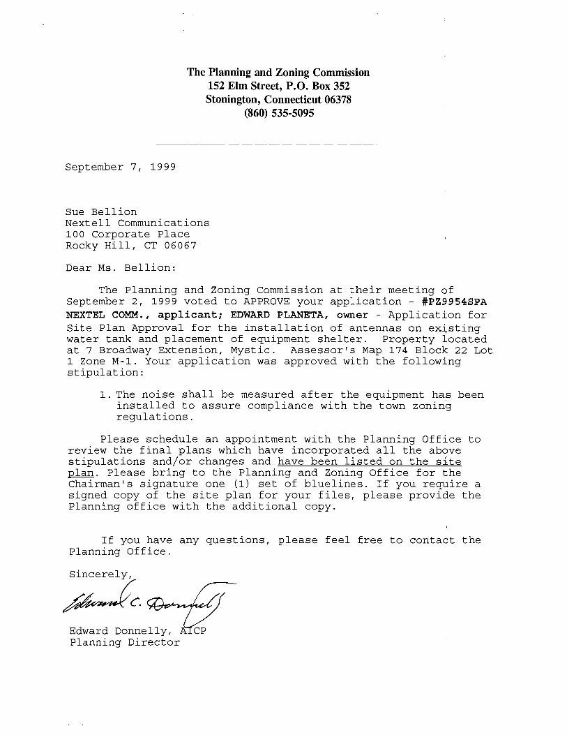


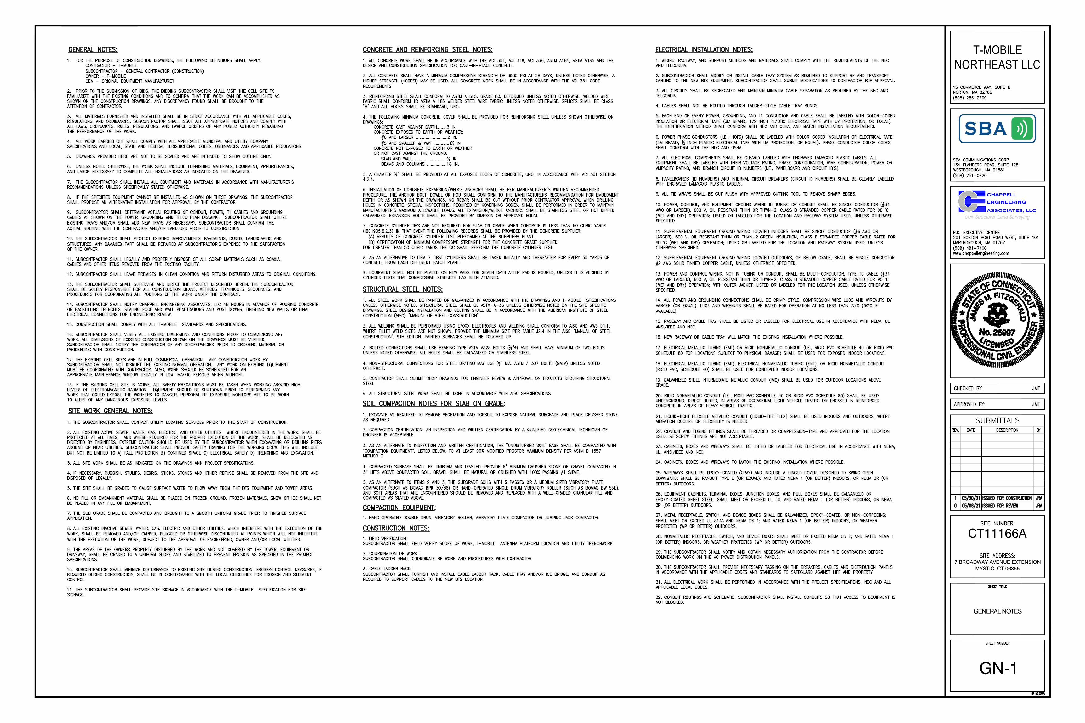
EXHIBIT 6

CT11166A
7 BROADWAY AVENUE EXTENSIONMYSTIC, CT 06355
CHAPPELL
ENGINEERING
ASSOCIATES, LLCCivil Structural Land Surveying
T-MOBILENORTHEAST LLC
T-1
TITLE SHEET
AT LEAST 72 HOURS PRIOR TODIGGING, THE CONTRACTOR IS
REQUIRED TO CALL DIG SAFE AT 811
···
···
······
········
CT11166A
7 BROADWAY AVENUE EXTENSIONMYSTIC, CT 06355
CHAPPELL
ENGINEERING
ASSOCIATES, LLCCivil Structural Land Surveying
T-MOBILENORTHEAST LLC
GENERAL NOTES
GN-1

CT11166A
7 BROADWAY AVENUE EXTENSIONMYSTIC, CT 06355
CHAPPELL
ENGINEERING
ASSOCIATES, LLCCivil Structural Land Surveying
T-MOBILENORTHEAST LLC
COMPOUND &EQUIPMENT PLANS
A-1
ERICSSON
CT11166A
7 BROADWAY AVENUE EXTENSIONMYSTIC, CT 06355
CHAPPELL
ENGINEERING
ASSOCIATES, LLCCivil Structural Land Surveying
T-MOBILENORTHEAST LLC
TOWER ELEVATIONS &ANTENNA PLANS
A-2
CT11166A
7 BROADWAY AVENUE EXTENSIONMYSTIC, CT 06355
CHAPPELL
ENGINEERING
ASSOCIATES, LLCCivil Structural Land Surveying
T-MOBILENORTHEAST LLC
SITE DETAILS
A-3

CT11166A
7 BROADWAY AVENUE EXTENSIONMYSTIC, CT 06355
CHAPPELL
ENGINEERING
ASSOCIATES, LLCCivil Structural Land Surveying
T-MOBILENORTHEAST LLC
ANTENNA &FEEDLINE CHARTS
A-4

CT11166A
7 BROADWAY AVENUE EXTENSIONMYSTIC, CT 06355
CHAPPELL
ENGINEERING
ASSOCIATES, LLCCivil Structural Land Surveying
T-MOBILENORTHEAST LLC
ELECTRIC & GROUNDINGDETAILS
E-1

EXHIBIT 7

ALL-POINTS TECHNOLOGY CORPORATION, P.C. 567 VAUXHALL STREET EXTENSION ∙ SUITE 311 ∙ WATERFORD, CT 06385 ∙ PHONE 860-663-1697
STRUCTURAL ANALYSIS REPORT 155’ ± WATER TOWER
MYSTIC, CONNECTICUT
Prepared for Chappell Engineering Associates, LLC
T-Mobile Site Ref: CT11166A; Mystic/Downtown
Site Address: 7 Broadway Avenue Extension Mystic, Connecticut 06355 APT Filing No. CT278251
May 10, 2021
ALL-POINTS TECHNOLOGY CORPORATION, P.C. 567 VAUXHALL STREET EXTENSION ∙ SUITE 311 ∙ WATERFORD, CT 06385 ∙ PHONE 860-663-1697
STRUCTURAL ANALYSIS REPORT 155’ ± WATER TOWER
MYSTIC, CONNECTICUT prepared for
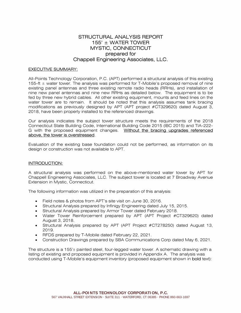
Chappell Engineering Associates, LLC. EXECUTIVE SUMMARY: All-Points Technology Corporation, P.C. (APT) performed a structural analysis of this existing 155-ft ± water tower. The analysis was performed for T-Mobile’s proposed removal of nine existing panel antennas and three existing remote radio heads (RRHs), and installation of nine new panel antennas and nine new RRHs as detailed below. The equipment is to be fed by three new hybrid cables. All other existing equipment, mounts and feed lines on the water tower are to remain. It should be noted that this analysis assumes tank bracing modifications as previously designed by APT (APT project #CT329620) dated August 3, 2018, have been properly installed to the referenced drawings. Our analysis indicates the subject tower structure meets the requirements of the 2018 Connecticut State Building Code, International Building Code 2015 (IBC 2015) and TIA-222-G with the proposed equipment changes. Without the bracing upgrades referenced above, the tower is overstressed. Evaluation of the existing base foundation could not be performed, as information on its design or construction was not available to APT. INTRODUCTION: A structural analysis was performed on the above-mentioned water tower by APT for Chappell Engineering Associates, LLC. The subject tower is located at 7 Broadway Avenue Extension in Mystic, Connecticut. The following information was utilized in the preparation of this analysis:
Field notes & photos from APT’s site visit on June 30, 2016. Structural Analysis prepared by Infinigy Engineering dated July 15, 2015. Structural Analysis prepared by Armor Tower dated February 2018. Water Tower Reinforcement prepared by APT (APT Project #CT329620) dated
August 3, 2018. Structural Analysis prepared by APT (APT Project #CT278250) dated August 13,
2019. RFDS prepared by T-Mobile dated February 22, 2021. Construction Drawings prepared by SBA Communications Corp dated May 6, 2021.
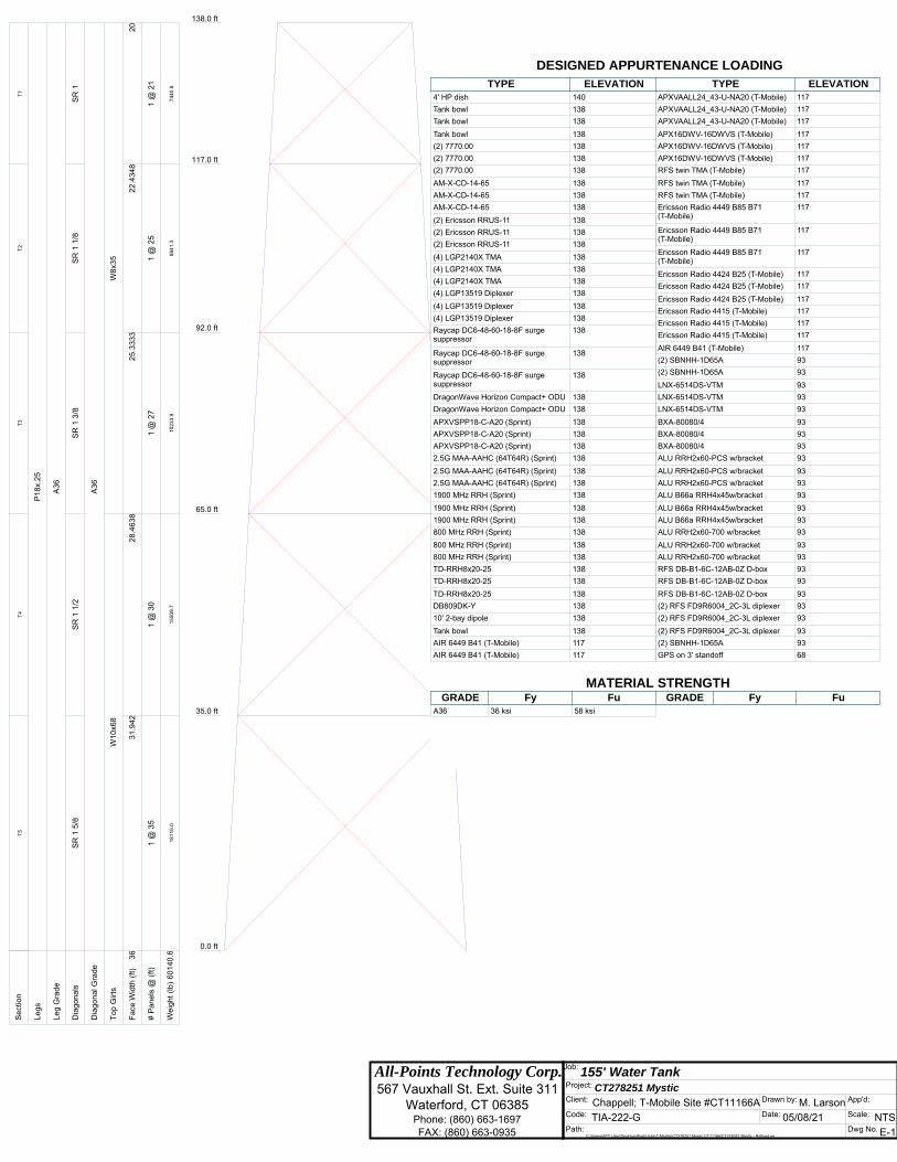
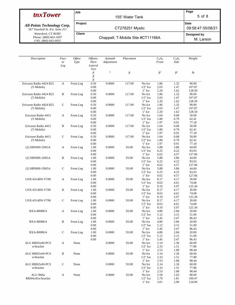
The structure is a 155’ painted steel, four-legged water tower. A schematic drawing with a listing of existing and proposed equipment is provided in Appendix A. The analysis was conducted using T-Mobile’s equipment inventory (proposed equipment shown in bold text):
Chappell Engineering Associates, LLC May 10, 2021 155-ft ± Water Tower Page 2 T-Mobile Site: CT11166A; Mystic/Downtown APT Job #CT278251
ALL-POINTS TECHNOLOGY CORPORATION, P.C. 567 VAUXHALL STREET EXTENSION ∙ SUITE 311 ∙ WATERFORD, CT 06385 ∙ PHONE 860-663-1697
Notes:
1. E = Existing; P = Proposed.
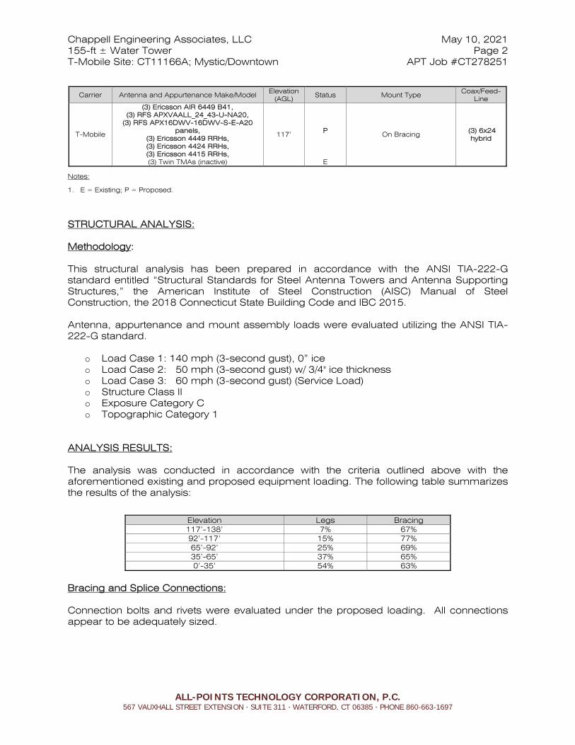
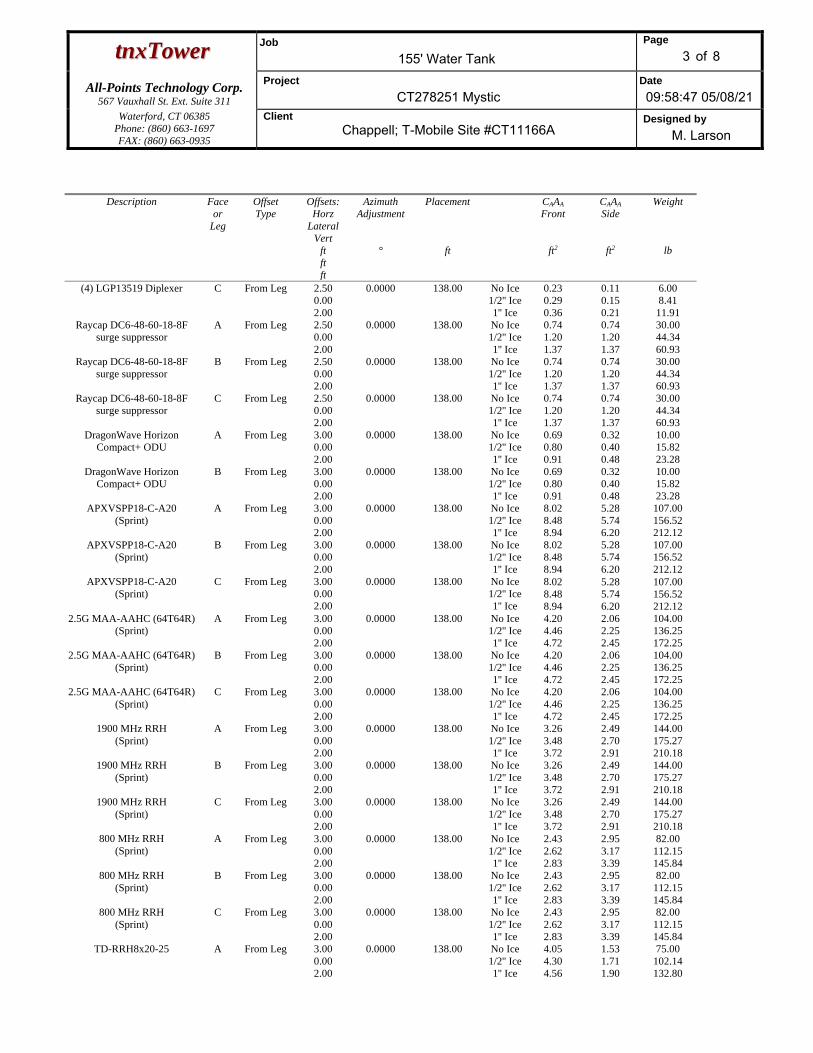
STRUCTURAL ANALYSIS: Methodology: This structural analysis has been prepared in accordance with the ANSI TIA-222-G standard entitled “Structural Standards for Steel Antenna Towers and Antenna Supporting Structures,” the American Institute of Steel Construction (AISC) Manual of Steel Construction, the 2018 Connecticut State Building Code and IBC 2015.
Antenna, appurtenance and mount assembly loads were evaluated utilizing the ANSI TIA-222-G standard.
o Load Case 1: 140 mph (3-second gust), 0” ice o Load Case 2: 50 mph (3-second gust) w/ 3/4" ice thickness o Load Case 3: 60 mph (3-second gust) (Service Load) o Structure Class II o Exposure Category C o Topographic Category 1
ANALYSIS RESULTS:
The analysis was conducted in accordance with the criteria outlined above with the aforementioned existing and proposed equipment loading. The following table summarizes the results of the analysis:
Elevation Legs Bracing 117’-138’ 7% 67% 92’-117’ 15% 77% 65’-92’ 25% 69% 35’-65’ 37% 65% 0’-35’ 54% 63%
Bracing and Splice Connections: Connection bolts and rivets were evaluated under the proposed loading. All connections appear to be adequately sized.
Carrier Antenna and Appurtenance Make/Model Elevation (AGL)
Status Mount Type Coax/Feed-Line
T-Mobile
(3) Ericsson AIR 6449 B41, (3) RFS APXVAALL_24_43-U-NA20,
(3) RFS APX16DWV-16DWV-S-E-A20 panels,
(3) Ericsson 4449 RRHs, (3) Ericsson 4424 RRHs, (3) Ericsson 4415 RRHs, (3) Twin TMAs (inactive)
117’
P
E
On Bracing (3) 6x24 hybrid
Chappell Engineering Associates, LLC May 10, 2021 155-ft ± Water Tower Page 3 T-Mobile Site: CT11166A; Mystic/Downtown APT Job #CT278251
ALL-POINTS TECHNOLOGY CORPORATION, P.C. 567 VAUXHALL STREET EXTENSION ∙ SUITE 311 ∙ WATERFORD, CT 06385 ∙ PHONE 860-663-1697
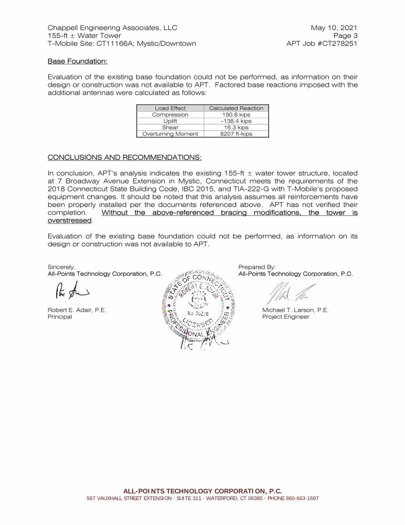
Base Foundation: Evaluation of the existing base foundation could not be performed, as information on their design or construction was not available to APT. Factored base reactions imposed with the additional antennas were calculated as follows:
Load Effect Calculated Reaction Compression 190.8 kips
Uplift -138.4 kips Shear 16.3 kips
Overturning Moment 8207 ft-kips
CONCLUSIONS AND RECOMMENDATIONS: In conclusion, APT’s analysis indicates the existing 155-ft ± water tower structure, located at 7 Broadway Avenue Extension in Mystic, Connecticut meets the requirements of the 2018 Connecticut State Building Code, IBC 2015, and TIA-222-G with T-Mobile’s proposed equipment changes. It should be noted that this analysis assumes all reinforcements have been properly installed per the documents referenced above. APT has not verified their completion. Without the above-referenced bracing modifications, the tower is overstressed. Evaluation of the existing base foundation could not be performed, as information on its design or construction was not available to APT. Sincerely, Prepared By: All-Points Technology Corporation, P.C. All-Points Technology Corporation, P.C.
Robert E. Adair, P.E. Michael T. Larson, P.E. Principal Project Engineer
Chappell Engineering Associates, LLC May 10, 2021 155-ft ± Water Tower Page 4 T-Mobile Site: CT11166A; Mystic/Downtown APT Job #CT278251
ALL-POINTS TECHNOLOGY CORPORATION, P.C. 567 VAUXHALL STREET EXTENSION ∙ SUITE 311 ∙ WATERFORD, CT 06385 ∙ PHONE 860-663-1697
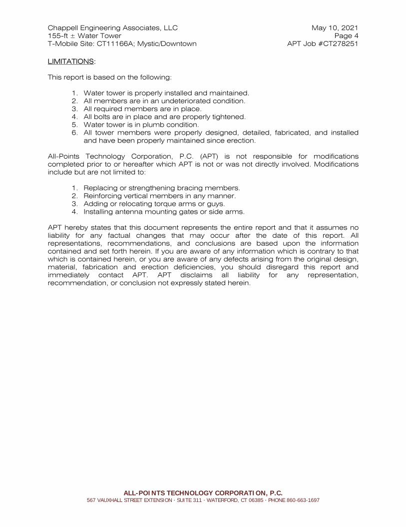
LIMITATIONS: This report is based on the following:
1. Water tower is properly installed and maintained. 2. All members are in an undeteriorated condition. 3. All required members are in place. 4. All bolts are in place and are properly tightened. 5. Water tower is in plumb condition. 6. All tower members were properly designed, detailed, fabricated, and installed
and have been properly maintained since erection. All-Points Technology Corporation, P.C. (APT) is not responsible for modifications completed prior to or hereafter which APT is not or was not directly involved. Modifications include but are not limited to:
1. Replacing or strengthening bracing members. 2. Reinforcing vertical members in any manner. 3. Adding or relocating torque arms or guys. 4. Installing antenna mounting gates or side arms.
APT hereby states that this document represents the entire report and that it assumes no liability for any factual changes that may occur after the date of this report. All representations, recommendations, and conclusions are based upon the information contained and set forth herein. If you are aware of any information which is contrary to that which is contained herein, or you are aware of any defects arising from the original design, material, fabrication and erection deficiencies, you should disregard this report and immediately contact APT. APT disclaims all liability for any representation, recommendation, or conclusion not expressly stated herein.

Appendix ATower Schematic
All-Points Technology Corp. 567 Vauxhall St. Ext. Suite 311
Waterford, CT 06385 Phone: (860) 663-1697 FAX: (860) 663-0935
Job: 155' Water Tank Project: CT278251 Mystic Client: Chappell; T-Mobile Site #CT11166A Drawn by: M. Larson App'd:
Code: TIA-222-G Date: 05/08/21 Scale: NTS Path:
C:\Users\APT User\Desktop\Work\Jobs\T-Mobile\CT278251 Mystic CT11166\CT278251 Mystic - Refined.eri Dwg No. E-1
138.0 ft
117.0 ft
92.0 ft
65.0 ft
35.0 ft
0.0 ft
Sec
tion
T1T2
T3T4
T5
Leg
sP1
8x.2
5
Leg
Gra
deA3
6
Dia
gona
lsSR
1SR
1 1
/8SR
1 3
/8SR
1 1
/2SR
1 5
/8
Dia
gona
l Gra
deA3
6
Top
Girt
sW
8x35
W10
x68
Fac
e W
idth
(ft)
2022
.434
825
.333
328
.463
831
.942
36
# P
anel
s @
(ft)
1 @
21
1 @
25
1 @
27
1 @
30
1 @
35
Wei
ght (
lb)
7440
.888
41.3
1023
3.9
1550
9.7
1811
5.0
6014
0.6
4' HP dish 140 Tank bowl 138 Tank bowl 138 Tank bowl 138 (2) 7770.00 138 (2) 7770.00 138 (2) 7770.00 138 AM-X-CD-14-65 138 AM-X-CD-14-65 138 AM-X-CD-14-65 138 (2) Ericsson RRUS-11 138 (2) Ericsson RRUS-11 138 (2) Ericsson RRUS-11 138 (4) LGP2140X TMA 138 (4) LGP2140X TMA 138 (4) LGP2140X TMA 138 (4) LGP13519 Diplexer 138 (4) LGP13519 Diplexer 138 (4) LGP13519 Diplexer 138 Raycap DC6-48-60-18-8F surge suppressor
138 Raycap DC6-48-60-18-8F surge suppressor
138 Raycap DC6-48-60-18-8F surge suppressor
138 DragonWave Horizon Compact+ ODU 138 DragonWave Horizon Compact+ ODU 138 APXVSPP18-C-A20 (Sprint) 138 APXVSPP18-C-A20 (Sprint) 138 APXVSPP18-C-A20 (Sprint) 138 2.5G MAA-AAHC (64T64R) (Sprint) 138 2.5G MAA-AAHC (64T64R) (Sprint) 138 2.5G MAA-AAHC (64T64R) (Sprint) 138 1900 MHz RRH (Sprint) 138 1900 MHz RRH (Sprint) 138 1900 MHz RRH (Sprint) 138 800 MHz RRH (Sprint) 138 800 MHz RRH (Sprint) 138 800 MHz RRH (Sprint) 138 TD-RRH8x20-25 138 TD-RRH8x20-25 138 TD-RRH8x20-25 138 DB809DK-Y 138 10' 2-bay dipole 138 Tank bowl 138 AIR 6449 B41 (T-Mobile) 117 AIR 6449 B41 (T-Mobile) 117 APXVAALL24_43-U-NA20 (T-Mobile) 117 APXVAALL24_43-U-NA20 (T-Mobile) 117 APXVAALL24_43-U-NA20 (T-Mobile) 117 APX16DWV-16DWVS (T-Mobile) 117 APX16DWV-16DWVS (T-Mobile) 117 APX16DWV-16DWVS (T-Mobile) 117 RFS twin TMA (T-Mobile) 117 RFS twin TMA (T-Mobile) 117 RFS twin TMA (T-Mobile) 117 Ericsson Radio 4449 B85 B71 (T-Mobile)
117 Ericsson Radio 4449 B85 B71 (T-Mobile)
117 Ericsson Radio 4449 B85 B71 (T-Mobile)
117 Ericsson Radio 4424 B25 (T-Mobile) 117 Ericsson Radio 4424 B25 (T-Mobile) 117 Ericsson Radio 4424 B25 (T-Mobile) 117 Ericsson Radio 4415 (T-Mobile) 117 Ericsson Radio 4415 (T-Mobile) 117 Ericsson Radio 4415 (T-Mobile) 117 AIR 6449 B41 (T-Mobile) 117 (2) SBNHH-1D65A 93 (2) SBNHH-1D65A 93 LNX-6514DS-VTM 93 LNX-6514DS-VTM 93 LNX-6514DS-VTM 93 BXA-80080/4 93 BXA-80080/4 93 BXA-80080/4 93 ALU RRH2x60-PCS w/bracket 93 ALU RRH2x60-PCS w/bracket 93 ALU RRH2x60-PCS w/bracket 93 ALU B66a RRH4x45w/bracket 93 ALU B66a RRH4x45w/bracket 93 ALU B66a RRH4x45w/bracket 93 ALU RRH2x60-700 w/bracket 93 ALU RRH2x60-700 w/bracket 93 ALU RRH2x60-700 w/bracket 93 RFS DB-B1-6C-12AB-0Z D-box 93 RFS DB-B1-6C-12AB-0Z D-box 93 RFS DB-B1-6C-12AB-0Z D-box 93 (2) RFS FD9R6004_2C-3L diplexer 93 (2) RFS FD9R6004_2C-3L diplexer 93 (2) RFS FD9R6004_2C-3L diplexer 93 (2) SBNHH-1D65A 93 GPS on 3' standoff 68DESIGNED APPURTENANCE LOADINGTYPE TYPEELEVATION ELEVATION
4' HP dish 140 Tank bowl 138 Tank bowl 138 Tank bowl 138 (2) 7770.00 138 (2) 7770.00 138 (2) 7770.00 138 AM-X-CD-14-65 138 AM-X-CD-14-65 138 AM-X-CD-14-65 138 (2) Ericsson RRUS-11 138 (2) Ericsson RRUS-11 138 (2) Ericsson RRUS-11 138 (4) LGP2140X TMA 138 (4) LGP2140X TMA 138 (4) LGP2140X TMA 138 (4) LGP13519 Diplexer 138 (4) LGP13519 Diplexer 138 (4) LGP13519 Diplexer 138 Raycap DC6-48-60-18-8F surge suppressor
138
Raycap DC6-48-60-18-8F surge suppressor
138
Raycap DC6-48-60-18-8F surge suppressor
138
DragonWave Horizon Compact+ ODU 138 DragonWave Horizon Compact+ ODU 138 APXVSPP18-C-A20 (Sprint) 138 APXVSPP18-C-A20 (Sprint) 138 APXVSPP18-C-A20 (Sprint) 138 2.5G MAA-AAHC (64T64R) (Sprint) 138 2.5G MAA-AAHC (64T64R) (Sprint) 138 2.5G MAA-AAHC (64T64R) (Sprint) 138 1900 MHz RRH (Sprint) 138 1900 MHz RRH (Sprint) 138 1900 MHz RRH (Sprint) 138 800 MHz RRH (Sprint) 138 800 MHz RRH (Sprint) 138 800 MHz RRH (Sprint) 138 TD-RRH8x20-25 138 TD-RRH8x20-25 138 TD-RRH8x20-25 138 DB809DK-Y 138 10' 2-bay dipole 138 Tank bowl 138 AIR 6449 B41 (T-Mobile) 117 AIR 6449 B41 (T-Mobile) 117
APXVAALL24_43-U-NA20 (T-Mobile) 117 APXVAALL24_43-U-NA20 (T-Mobile) 117 APXVAALL24_43-U-NA20 (T-Mobile) 117 APX16DWV-16DWVS (T-Mobile) 117 APX16DWV-16DWVS (T-Mobile) 117 APX16DWV-16DWVS (T-Mobile) 117 RFS twin TMA (T-Mobile) 117 RFS twin TMA (T-Mobile) 117 RFS twin TMA (T-Mobile) 117 Ericsson Radio 4449 B85 B71 (T-Mobile)
117
Ericsson Radio 4449 B85 B71 (T-Mobile)
117
Ericsson Radio 4449 B85 B71 (T-Mobile)
117
Ericsson Radio 4424 B25 (T-Mobile) 117 Ericsson Radio 4424 B25 (T-Mobile) 117 Ericsson Radio 4424 B25 (T-Mobile) 117 Ericsson Radio 4415 (T-Mobile) 117 Ericsson Radio 4415 (T-Mobile) 117 Ericsson Radio 4415 (T-Mobile) 117 AIR 6449 B41 (T-Mobile) 117 (2) SBNHH-1D65A 93 (2) SBNHH-1D65A 93 LNX-6514DS-VTM 93 LNX-6514DS-VTM 93 LNX-6514DS-VTM 93 BXA-80080/4 93 BXA-80080/4 93 BXA-80080/4 93 ALU RRH2x60-PCS w/bracket 93 ALU RRH2x60-PCS w/bracket 93 ALU RRH2x60-PCS w/bracket 93 ALU B66a RRH4x45w/bracket 93 ALU B66a RRH4x45w/bracket 93 ALU B66a RRH4x45w/bracket 93 ALU RRH2x60-700 w/bracket 93 ALU RRH2x60-700 w/bracket 93 ALU RRH2x60-700 w/bracket 93 RFS DB-B1-6C-12AB-0Z D-box 93 RFS DB-B1-6C-12AB-0Z D-box 93 RFS DB-B1-6C-12AB-0Z D-box 93 (2) RFS FD9R6004_2C-3L diplexer 93 (2) RFS FD9R6004_2C-3L diplexer 93 (2) RFS FD9R6004_2C-3L diplexer 93 (2) SBNHH-1D65A 93 GPS on 3' standoff 68
MATERIAL STRENGTHGRADE GRADEFy FyFu Fu
A36 36 ksi 58 ksi

All-Points Technology Corp. 567 Vauxhall St. Ext. Suite 311
Waterford, CT 06385 Phone: (860) 663-1697 FAX: (860) 663-0935
Job: 155' Water Tank Project: CT278251 Mystic Client: Chappell; T-Mobile Site #CT11166A Drawn by: M. Larson App'd:
Code: TIA-222-G Date: 05/08/21 Scale: NTS Path:
C:\Users\APT User\Desktop\Work\Jobs\T-Mobile\CT278251 Mystic CT11166\CT278251 Mystic - Refined.eri Dwg No. E-1
138.0 ft
117.0 ft
92.0 ft
65.0 ft
35.0 ft
0.0 ft
REACTIONS - 108 mph WINDTORQUE 133246 lb-ft
86953 lbSHEAR
8206624 lb-ftMOMENT
118402 lbAXIAL
50 mph WIND - 0.7500 in ICETORQUE 33314 lb-ft
16876 lbSHEAR
1812953 lb-ftMOMENT
209576 lbAXIAL
SHEAR: 40940 lbUPLIFT: -138403 lb
SHEAR: 16315 lbDOWN: 190818 lb
MAX. CORNER REACTIONS AT BASE:
ARE FACTOREDALL REACTIONS
Sec
tion
T1T2
T3T4
T5
Leg
sP1
8x.2
5
Leg
Gra
deA3
6
Dia
gona
lsSR
1SR
1 1
/8SR
1 3
/8SR
1 1
/2SR
1 5
/8
Dia
gona
l Gra
deA3
6
Top
Girt
sW
8x35
W10
x68
Fac
e W
idth
(ft)
2022
.434
825
.333
328
.463
831
.942
36
# P
anel
s @
(ft)
1 @
21
1 @
25
1 @
27
1 @
30
1 @
35
Wei
ght (
lb)
7440
.888
41.3
1023
3.9
1550
9.7
1811
5.0
6014
0.6
MATERIAL STRENGTHGRADE GRADEFy FyFu Fu
A36 36 ksi 58 ksi

Appendix BCalculations

ttnnxxTToowweerr Job
155' Water Tank Page
1 of 8
All-Points Technology Corp. 567 Vauxhall St. Ext. Suite 311
Project
CT278251 Mystic Date 09:58:47 05/08/21
Waterford, CT 06385 Phone: (860) 663-1697 FAX: (860) 663-0935
Client Chappell; T-Mobile Site #CT11166A
Designed by M. Larson
Tower Input Data The main tower is a 4x free standing tower with an overall height of 138.00 ft above the ground line. The base of the tower is set at an elevation of 0.00 ft above the ground line. The face width of the tower is 20.00 ft at the top and 36.00 ft at the base. This tower is designed using the TIA-222-G standard. The following design criteria apply:
ASCE 7-10 Wind Data is used (wind speeds converted to nominal values). Basic wind speed of 108 mph. Ultimate wind speed of 140 mph. Structure Class II. Exposure Category C. Topographic Category 1. Crest Height 0.00 ft. Nominal ice thickness of 0.7500 in. Ice thickness is considered to increase with height. Ice density of 56 pcf. A wind speed of 50 mph is used in combination with ice. Temperature drop of 50 °F. Deflections calculated using a wind speed of 60 mph. Tension only take-up is 0.0313 in. A non-linear (P-delta) analysis was used. Pressures are calculated at each section. Stress ratio used in tower member design is 1. Local bending stresses due to climbing loads, feed line supports, and appurtenance mounts are not considered.
Feed Line/Linear Appurtenances
Description Face or
Leg
Allow Shield
Exclude From
Torque Calculation
Component Type
Placement
ft
Face Offset
in
Lateral Offset
(Frac FW)
# # Per Row
Clear Spacing
in
Width or Diameter
in
Perimeter
in
Weight
plf
1 5/8 C No No Ar (CaAa) 138.00 - 8.00
0.0000 0.5 18 6 0.5000 1.9800 1.04
7/8 D No No Ar (CaAa) 138.00 - 8.00
0.0000 0.5 2 2 1.1100 1.1100 0.54
1-1/4'' Hybrid fiber-power
cable
C No No Ar (CaAa) 138.00 - 8.00
0.0000 0.5 3 3 0.7500 1.2500 1.30
1/2 C No No Ar (CaAa) 138.00 - 8.00
0.0000 0.5 2 2 0.5800 0.5800 0.25
6x24 fiber cable
(T-Mobile)
B No No Ar (CaAa) 117.00 - 8.00
0.0000 0.5 3 3 0.5000 1.6730 2.22
2'' conduit C No No Ar (CaAa) 138.00 - 8.00
0.0000 0.5 1 1 2.0000 2.0000 2.00
1 5/8 D No No Ar (CaAa) 93.00 - 8.00 0.0000 0.5 12 6 0.5000 1.9800 1.04 1.57'' Hybrid fiber-power
cable
D No No Ar (CaAa) 93.00 - 8.00 0.0000 0.5 3 3 0.7500 1.5700 1.50
Feedline Ladder (Af)
C No No Ar (CaAa) 138.00 - 10.00
0.0000 0.5 1 1 3.0000 3.0000 8.40
36'' standpipe A No No Ar (CaAa) 130.00 - 65.00
-120.0000
0 1 1 36.0000 36.0000 47.44

ttnnxxTToowweerr Job
155' Water Tank Page
2 of 8
All-Points Technology Corp. 567 Vauxhall St. Ext. Suite 311
Project
CT278251 Mystic Date 09:58:47 05/08/21
Waterford, CT 06385 Phone: (860) 663-1697 FAX: (860) 663-0935
Client Chappell; T-Mobile Site #CT11166A
Designed by M. Larson
Discrete Tower Loads
Description Face or
Leg
Offset Type
Offsets: Horz
Lateral Vert
ft ft ft
Azimuth Adjustment
°
Placement
ft
CAAA Front
ft2
CAAA Side
ft2
Weight
lb
Tank bowl A None 0.0000 138.00 No Ice 1/2'' Ice 1'' Ice
75.66 76.96 78.26
75.66 76.96 78.26
5844.00 6893.00 7942.00
Tank bowl B None 0.0000 138.00 No Ice 1/2'' Ice 1'' Ice
75.66 76.96 78.26
75.66 76.96 78.26
5844.00 6893.00 7942.00
Tank bowl C None 0.0000 138.00 No Ice 1/2'' Ice 1'' Ice
75.66 76.96 78.26
75.66 76.96 78.26
5844.00 6893.00 7942.00
Tank bowl D None 0.0000 138.00 No Ice 1/2'' Ice 1'' Ice
75.66 76.96 78.26
75.66 76.96 78.26
5844.00 6893.00 7942.00
(2) 7770.00 A From Leg 3.00 0.00 2.00
0.0000 138.00 No Ice 1/2'' Ice 1'' Ice
5.51 5.87 6.23
2.93 3.27 3.63
35.00 67.63
105.06 (2) 7770.00 B From Leg 3.00
0.00 2.00
0.0000 138.00 No Ice 1/2'' Ice 1'' Ice
5.51 5.87 6.23
2.93 3.27 3.63
35.00 67.63
105.06 (2) 7770.00 C From Leg 3.00
0.00 2.00
0.0000 138.00 No Ice 1/2'' Ice 1'' Ice
5.51 5.87 6.23
2.93 3.27 3.63
35.00 67.63
105.06 AM-X-CD-14-65 A From Leg 3.00
0.00 2.00
0.0000 138.00 No Ice 1/2'' Ice 1'' Ice
4.99 5.32 5.65
2.83 3.14 3.45
40.00 71.95
108.36 AM-X-CD-14-65 B From Leg 3.00
0.00 2.00
0.0000 138.00 No Ice 1/2'' Ice 1'' Ice
4.99 5.32 5.65
2.83 3.14 3.45
40.00 71.95
108.36 AM-X-CD-14-65 C From Leg 3.00
0.00 2.00
0.0000 138.00 No Ice 1/2'' Ice 1'' Ice
4.99 5.32 5.65
2.83 3.14 3.45
40.00 71.95
108.36 (2) Ericsson RRUS-11 A From Leg 2.50
0.00 2.00
0.0000 138.00 No Ice 1/2'' Ice 1'' Ice
2.79 3.00 3.21
1.02 1.16 1.30
55.00 75.86 99.77
(2) Ericsson RRUS-11 B From Leg 2.50 0.00 2.00
0.0000 138.00 No Ice 1/2'' Ice 1'' Ice
2.79 3.00 3.21
1.02 1.16 1.30
55.00 75.86 99.77
(2) Ericsson RRUS-11 C From Leg 2.50 0.00 2.00
0.0000 138.00 No Ice 1/2'' Ice 1'' Ice
2.79 3.00 3.21
1.02 1.16 1.30
55.00 75.86 99.77
(4) LGP2140X TMA A From Leg 2.50 0.00 2.00
0.0000 138.00 No Ice 1/2'' Ice 1'' Ice
1.08 1.21 1.35
0.36 0.45 0.56
20.00 27.13 36.14
(4) LGP2140X TMA B From Leg 2.50 0.00 2.00
0.0000 138.00 No Ice 1/2'' Ice 1'' Ice
1.08 1.21 1.35
0.36 0.45 0.56
20.00 27.13 36.14
(4) LGP2140X TMA C From Leg 2.50 0.00 2.00
0.0000 138.00 No Ice 1/2'' Ice 1'' Ice
1.08 1.21 1.35
0.36 0.45 0.56
20.00 27.13 36.14
(4) LGP13519 Diplexer A From Leg 2.50 0.00 2.00
0.0000 138.00 No Ice 1/2'' Ice 1'' Ice
0.23 0.29 0.36
0.11 0.15 0.21
6.00 8.41 11.91
(4) LGP13519 Diplexer B From Leg 2.50 0.00 2.00
0.0000 138.00 No Ice 1/2'' Ice 1'' Ice
0.23 0.29 0.36
0.11 0.15 0.21
6.00 8.41 11.91
ttnnxxTToowweerr Job
155' Water Tank Page
3 of 8
All-Points Technology Corp. 567 Vauxhall St. Ext. Suite 311
Project
CT278251 Mystic Date 09:58:47 05/08/21
Waterford, CT 06385 Phone: (860) 663-1697 FAX: (860) 663-0935
Client Chappell; T-Mobile Site #CT11166A
Designed by M. Larson
Description Face or
Leg
Offset Type
Offsets: Horz
Lateral Vert
ft ft ft
Azimuth Adjustment
°
Placement
ft
CAAA Front
ft2
CAAA Side
ft2
Weight
lb
(4) LGP13519 Diplexer C From Leg 2.50 0.00 2.00
0.0000 138.00 No Ice 1/2'' Ice 1'' Ice
0.23 0.29 0.36
0.11 0.15 0.21
6.00 8.41 11.91
Raycap DC6-48-60-18-8F surge suppressor
A From Leg 2.50 0.00 2.00
0.0000 138.00 No Ice 1/2'' Ice 1'' Ice
0.74 1.20 1.37
0.74 1.20 1.37
30.00 44.34 60.93
Raycap DC6-48-60-18-8F surge suppressor
B From Leg 2.50 0.00 2.00
0.0000 138.00 No Ice 1/2'' Ice 1'' Ice
0.74 1.20 1.37
0.74 1.20 1.37
30.00 44.34 60.93
Raycap DC6-48-60-18-8F surge suppressor
C From Leg 2.50 0.00 2.00
0.0000 138.00 No Ice 1/2'' Ice 1'' Ice
0.74 1.20 1.37
0.74 1.20 1.37
30.00 44.34 60.93
DragonWave Horizon Compact+ ODU
A From Leg 3.00 0.00 2.00
0.0000 138.00 No Ice 1/2'' Ice 1'' Ice
0.69 0.80 0.91
0.32 0.40 0.48
10.00 15.82 23.28
DragonWave Horizon Compact+ ODU
B From Leg 3.00 0.00 2.00
0.0000 138.00 No Ice 1/2'' Ice 1'' Ice
0.69 0.80 0.91
0.32 0.40 0.48
10.00 15.82 23.28
APXVSPP18-C-A20 (Sprint)
A From Leg 3.00 0.00 2.00
0.0000 138.00 No Ice 1/2'' Ice 1'' Ice
8.02 8.48 8.94
5.28 5.74 6.20
107.00 156.52 212.12
APXVSPP18-C-A20 (Sprint)
B From Leg 3.00 0.00 2.00
0.0000 138.00 No Ice 1/2'' Ice 1'' Ice
8.02 8.48 8.94
5.28 5.74 6.20
107.00 156.52 212.12
APXVSPP18-C-A20 (Sprint)
C From Leg 3.00 0.00 2.00
0.0000 138.00 No Ice 1/2'' Ice 1'' Ice
8.02 8.48 8.94
5.28 5.74 6.20
107.00 156.52 212.12
2.5G MAA-AAHC (64T64R) (Sprint)
A From Leg 3.00 0.00 2.00
0.0000 138.00 No Ice 1/2'' Ice 1'' Ice
4.20 4.46 4.72
2.06 2.25 2.45
104.00 136.25 172.25
2.5G MAA-AAHC (64T64R) (Sprint)
B From Leg 3.00 0.00 2.00
0.0000 138.00 No Ice 1/2'' Ice 1'' Ice
4.20 4.46 4.72
2.06 2.25 2.45
104.00 136.25 172.25
2.5G MAA-AAHC (64T64R) (Sprint)
C From Leg 3.00 0.00 2.00
0.0000 138.00 No Ice 1/2'' Ice 1'' Ice
4.20 4.46 4.72
2.06 2.25 2.45
104.00 136.25 172.25
1900 MHz RRH (Sprint)
A From Leg 3.00 0.00 2.00
0.0000 138.00 No Ice 1/2'' Ice 1'' Ice
3.26 3.48 3.72
2.49 2.70 2.91
144.00 175.27 210.18
1900 MHz RRH (Sprint)
B From Leg 3.00 0.00 2.00
0.0000 138.00 No Ice 1/2'' Ice 1'' Ice
3.26 3.48 3.72
2.49 2.70 2.91
144.00 175.27 210.18
1900 MHz RRH (Sprint)
C From Leg 3.00 0.00 2.00
0.0000 138.00 No Ice 1/2'' Ice 1'' Ice
3.26 3.48 3.72
2.49 2.70 2.91
144.00 175.27 210.18
800 MHz RRH (Sprint)
A From Leg 3.00 0.00 2.00
0.0000 138.00 No Ice 1/2'' Ice 1'' Ice
2.43 2.62 2.83
2.95 3.17 3.39
82.00 112.15 145.84
800 MHz RRH (Sprint)
B From Leg 3.00 0.00 2.00
0.0000 138.00 No Ice 1/2'' Ice 1'' Ice
2.43 2.62 2.83
2.95 3.17 3.39
82.00 112.15 145.84
800 MHz RRH (Sprint)
C From Leg 3.00 0.00 2.00
0.0000 138.00 No Ice 1/2'' Ice 1'' Ice
2.43 2.62 2.83
2.95 3.17 3.39
82.00 112.15 145.84
TD-RRH8x20-25 A From Leg 3.00 0.00 2.00
0.0000 138.00 No Ice 1/2'' Ice 1'' Ice
4.05 4.30 4.56
1.53 1.71 1.90
75.00 102.14 132.80

ttnnxxTToowweerr Job
155' Water Tank Page
4 of 8
All-Points Technology Corp. 567 Vauxhall St. Ext. Suite 311
Project
CT278251 Mystic Date 09:58:47 05/08/21
Waterford, CT 06385 Phone: (860) 663-1697 FAX: (860) 663-0935
Client Chappell; T-Mobile Site #CT11166A
Designed by M. Larson
Description Face or
Leg
Offset Type
Offsets: Horz
Lateral Vert
ft ft ft
Azimuth Adjustment
°
Placement
ft
CAAA Front
ft2
CAAA Side
ft2
Weight
lb
TD-RRH8x20-25 B From Leg 3.00 0.00 2.00
0.0000 138.00 No Ice 1/2'' Ice 1'' Ice
4.05 4.30 4.56
1.53 1.71 1.90
75.00 102.14 132.80
TD-RRH8x20-25 C From Leg 3.00 0.00 2.00
0.0000 138.00 No Ice 1/2'' Ice 1'' Ice
4.05 4.30 4.56
1.53 1.71 1.90
75.00 102.14 132.80
DB809DK-Y C From Leg 3.00 0.00 2.00
0.0000 138.00 No Ice 1/2'' Ice 1'' Ice
3.39 4.55 5.73
3.39 4.55 5.73
32.00 56.57 88.49
10' 2-bay dipole C From Leg 3.00 0.00 2.00
0.0000 138.00 No Ice 1/2'' Ice 1'' Ice
2.50 3.53 4.58
2.50 3.53 4.58
75.00 93.64
118.79 AIR 6449 B41
(T-Mobile) A From Leg 1.00
0.00 0.00
0.0000 117.00 No Ice 1/2'' Ice 1'' Ice
5.68 5.98 6.29
2.49 2.72 2.95
128.00 167.12 210.46
AIR 6449 B41 (T-Mobile)
B From Leg 1.00 0.00 0.00
0.0000 117.00 No Ice 1/2'' Ice 1'' Ice
5.68 5.98 6.29
2.49 2.72 2.95
128.00 167.12 210.46
AIR 6449 B41 (T-Mobile)
C From Leg 1.00 0.00 0.00
0.0000 117.00 No Ice 1/2'' Ice 1'' Ice
5.68 5.98 6.29
2.49 2.72 2.95
128.00 167.12 210.46
APXVAALL24_43-U-NA20 (T-Mobile)
A From Leg 1.00 0.00 0.00
0.0000 117.00 No Ice 1/2'' Ice 1'' Ice
20.24 20.89 21.54
8.73 9.33 9.93
65.00 176.81 297.14
APXVAALL24_43-U-NA20 (T-Mobile)
B From Leg 1.00 0.00 0.00
0.0000 117.00 No Ice 1/2'' Ice 1'' Ice
20.24 20.89 21.54
8.73 9.33 9.93
65.00 176.81 297.14
APXVAALL24_43-U-NA20 (T-Mobile)
C From Leg 1.00 0.00 0.00
0.0000 117.00 No Ice 1/2'' Ice 1'' Ice
20.24 20.89 21.54
8.73 9.33 9.93
65.00 176.81 297.14
APX16DWV-16DWVS (T-Mobile)
A From Leg 1.00 0.00 0.00
0.0000 117.00 No Ice 1/2'' Ice 1'' Ice
6.08 6.44 6.80
2.00 2.33 2.66
25.00 56.34 92.36
APX16DWV-16DWVS (T-Mobile)
B From Leg 1.00 0.00 0.00
0.0000 117.00 No Ice 1/2'' Ice 1'' Ice
6.08 6.44 6.80
2.00 2.33 2.66
25.00 56.34 92.36
APX16DWV-16DWVS (T-Mobile)
C From Leg 1.00 0.00 0.00
0.0000 117.00 No Ice 1/2'' Ice 1'' Ice
6.08 6.44 6.80
2.00 2.33 2.66
25.00 56.34 92.36
RFS twin TMA (T-Mobile)
A From Leg 0.50 0.00 0.00
0.0000 117.00 No Ice 1/2'' Ice 1'' Ice
1.00 1.13 1.26
0.41 0.50 0.59
13.00 20.62 30.11
RFS twin TMA (T-Mobile)
B From Leg 0.50 0.00 0.00
0.0000 117.00 No Ice 1/2'' Ice 1'' Ice
1.00 1.13 1.26
0.41 0.50 0.59
13.00 20.62 30.11
RFS twin TMA (T-Mobile)
C From Leg 0.50 0.00 0.00
0.0000 117.00 No Ice 1/2'' Ice 1'' Ice
1.00 1.13 1.26
0.41 0.50 0.59
13.00 20.62 30.11
Ericsson Radio 4449 B85 B71
(T-Mobile)
A From Leg 0.50 0.00 0.00
0.0000 117.00 No Ice 1/2'' Ice 1'' Ice
1.97 2.15 2.33
1.58 1.74 1.91
85.00 104.72 127.35
Ericsson Radio 4449 B85 B71
(T-Mobile)
B From Leg 0.50 0.00 0.00
0.0000 117.00 No Ice 1/2'' Ice 1'' Ice
1.97 2.15 2.33
1.58 1.74 1.91
85.00 104.72 127.35
Ericsson Radio 4449 B85 B71
(T-Mobile)
C From Leg 0.50 0.00 0.00
0.0000 117.00 No Ice 1/2'' Ice 1'' Ice
1.97 2.15 2.33
1.58 1.74 1.91
85.00 104.72 127.35
ttnnxxTToowweerr Job
155' Water Tank Page
5 of 8
All-Points Technology Corp. 567 Vauxhall St. Ext. Suite 311
Project
CT278251 Mystic Date 09:58:47 05/08/21
Waterford, CT 06385 Phone: (860) 663-1697 FAX: (860) 663-0935
Client Chappell; T-Mobile Site #CT11166A
Designed by M. Larson
Description Face or
Leg
Offset Type
Offsets: Horz
Lateral Vert
ft ft ft
Azimuth Adjustment
°
Placement
ft
CAAA Front
ft2
CAAA Side
ft2
Weight
lb
Ericsson Radio 4424 B25 (T-Mobile)
A From Leg 0.50 0.00 0.00
0.0000 117.00 No Ice 1/2'' Ice 1'' Ice
1.86 2.03 2.20
1.32 1.47 1.62
90.00 107.87 128.50
Ericsson Radio 4424 B25 (T-Mobile)
B From Leg 0.50 0.00 0.00
0.0000 117.00 No Ice 1/2'' Ice 1'' Ice
1.86 2.03 2.20
1.32 1.47 1.62
90.00 107.87 128.50
Ericsson Radio 4424 B25 (T-Mobile)
C From Leg 0.50 0.00 0.00
0.0000 117.00 No Ice 1/2'' Ice 1'' Ice
1.86 2.03 2.20
1.32 1.47 1.62
90.00 107.87 128.50
Ericsson Radio 4415 (T-Mobile)
A From Leg 0.50 0.00 0.00
0.0000 117.00 No Ice 1/2'' Ice 1'' Ice
1.64 1.80 1.97
0.68 0.79 0.91
50.00 62.41 77.18
Ericsson Radio 4415 (T-Mobile)
B From Leg 0.50 0.00 0.00
0.0000 117.00 No Ice 1/2'' Ice 1'' Ice
1.64 1.80 1.97
0.68 0.79 0.91
50.00 62.41 77.18
Ericsson Radio 4415 (T-Mobile)
C From Leg 0.50 0.00 0.00
0.0000 117.00 No Ice 1/2'' Ice 1'' Ice
1.64 1.80 1.97
0.68 0.79 0.91
50.00 62.41 77.18
(2) SBNHH-1D65A A From Leg 1.00 0.00 0.00
0.0000 93.00 No Ice 1/2'' Ice 1'' Ice
5.88 6.25 6.62
3.86 4.22 4.57
44.00 83.03
127.06 (2) SBNHH-1D65A B From Leg 1.00
0.00 0.00
0.0000 93.00 No Ice 1/2'' Ice 1'' Ice
5.88 6.25 6.62
3.86 4.22 4.57
44.00 83.03
127.06 (2) SBNHH-1D65A C From Leg 1.00
0.00 0.00
0.0000 93.00 No Ice 1/2'' Ice 1'' Ice
5.88 6.25 6.62
3.86 4.22 4.57
44.00 83.03
127.06 LNX-6514DS-VTM A From Leg 1.00
0.00 0.00
0.0000 93.00 No Ice 1/2'' Ice 1'' Ice
8.17 8.63 9.10
4.17 4.61 5.07
30.00 74.68
125.36 LNX-6514DS-VTM B From Leg 1.00
0.00 0.00
0.0000 93.00 No Ice 1/2'' Ice 1'' Ice
8.17 8.63 9.10
4.17 4.61 5.07
30.00 74.68
125.36 LNX-6514DS-VTM C From Leg 1.00
0.00 0.00
0.0000 93.00 No Ice 1/2'' Ice 1'' Ice
8.17 8.63 9.10
4.17 4.61 5.07
30.00 74.68
125.36 BXA-80080/4 A From Leg 1.00
0.00 0.00
0.0000 93.00 No Ice 1/2'' Ice 1'' Ice
4.80 5.12 5.45
2.84 3.15 3.47
20.00 51.00 86.43
BXA-80080/4 B From Leg 1.00 0.00 0.00
0.0000 93.00 No Ice 1/2'' Ice 1'' Ice
4.80 5.12 5.45
2.84 3.15 3.47
20.00 51.00 86.43
BXA-80080/4 C From Leg 1.00 0.00 0.00
0.0000 93.00 No Ice 1/2'' Ice 1'' Ice
4.80 5.12 5.45
2.84 3.15 3.47
20.00 51.00 86.43
ALU RRH2x60-PCS w/bracket
A None 0.0000 93.00 No Ice 1/2'' Ice 1'' Ice
2.14 2.33 2.53
1.36 1.51 1.68
60.00 77.80 98.44
ALU RRH2x60-PCS w/bracket
B None 0.0000 93.00 No Ice 1/2'' Ice 1'' Ice
2.14 2.33 2.53
1.36 1.51 1.68
60.00 77.80 98.44
ALU RRH2x60-PCS w/bracket
C None 0.0000 93.00 No Ice 1/2'' Ice 1'' Ice
2.14 2.33 2.53
1.36 1.51 1.68
60.00 77.80 98.44
ALU B66a RRH4x45w/bracket
A None 0.0000 93.00 No Ice 1/2'' Ice 1'' Ice
2.58 2.79 3.01
1.63 1.81 2.00
80.00 100.47 124.06
ttnnxxTToowweerr Job
155' Water Tank Page
6 of 8
All-Points Technology Corp. 567 Vauxhall St. Ext. Suite 311
Project
CT278251 Mystic Date 09:58:47 05/08/21
Waterford, CT 06385 Phone: (860) 663-1697 FAX: (860) 663-0935
Client Chappell; T-Mobile Site #CT11166A
Designed by M. Larson
Description Face or
Leg
Offset Type
Offsets: Horz
Lateral Vert
ft ft ft
Azimuth Adjustment
°
Placement
ft
CAAA Front
ft2
CAAA Side
ft2
Weight
lb
ALU B66a RRH4x45w/bracket
B None 0.0000 93.00 No Ice 1/2'' Ice 1'' Ice
2.58 2.79 3.01
1.63 1.81 2.00
80.00 100.47 124.06
ALU B66a RRH4x45w/bracket
C None 0.0000 93.00 No Ice 1/2'' Ice 1'' Ice
2.58 2.79 3.01
1.63 1.81 2.00
80.00 100.47 124.06
ALU RRH2x60-700 w/bracket
A None 0.0000 93.00 No Ice 1/2'' Ice 1'' Ice
3.35 3.60 3.87
2.02 2.25 2.49
60.00 83.19
110.02 ALU RRH2x60-700
w/bracket B None 0.0000 93.00 No Ice
1/2'' Ice 1'' Ice
3.35 3.60 3.87
2.02 2.25 2.49
60.00 83.19
110.02 ALU RRH2x60-700
w/bracket C None 0.0000 93.00 No Ice
1/2'' Ice 1'' Ice
3.35 3.60 3.87
2.02 2.25 2.49
60.00 83.19
110.02 RFS DB-B1-6C-12AB-0Z
D-box A None 0.0000 93.00 No Ice
1/2'' Ice 1'' Ice
2.52 2.71 2.92
1.64 1.81 1.98
27.00 49.89 75.90
RFS DB-B1-6C-12AB-0Z D-box
B None 0.0000 93.00 No Ice 1/2'' Ice 1'' Ice
2.52 2.71 2.92
1.64 1.81 1.98
27.00 49.89 75.90
RFS DB-B1-6C-12AB-0Z D-box
C None 0.0000 93.00 No Ice 1/2'' Ice 1'' Ice
2.52 2.71 2.92
1.64 1.81 1.98
27.00 49.89 75.90
(2) RFS FD9R6004_2C-3L diplexer
A None 0.0000 93.00 No Ice 1/2'' Ice 1'' Ice
0.31 0.39 0.47
0.08 0.12 0.17
5.00 7.30 10.69
(2) RFS FD9R6004_2C-3L diplexer
B None 0.0000 93.00 No Ice 1/2'' Ice 1'' Ice
0.31 0.39 0.47
0.08 0.12 0.17
5.00 7.30 10.69
(2) RFS FD9R6004_2C-3L diplexer
C None 0.0000 93.00 No Ice 1/2'' Ice 1'' Ice
0.31 0.39 0.47
0.08 0.12 0.17
5.00 7.30 10.69
GPS on 3' standoff C From Leg 1.00 0.00 0.00
0.0000 68.00 No Ice 1/2'' Ice 1'' Ice
0.60 0.79 0.99
0.60 0.79 0.99
50.00 55.81 63.86
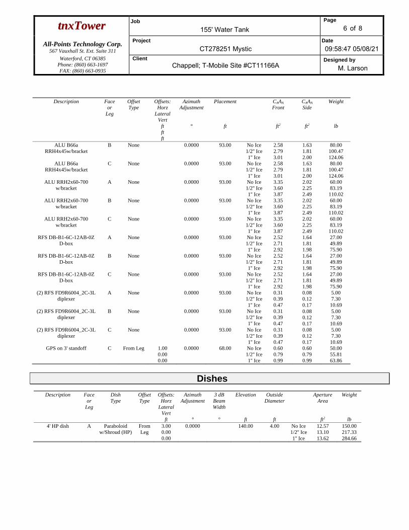
Dishes
Description Face or
Leg
Dish Type
Offset Type
Offsets: Horz
Lateral Vert
ft
Azimuth Adjustment
°
3 dB Beam Width
°
Elevation
ft
Outside Diameter
ft
Aperture Area
ft2
Weight
lb 4' HP dish A Paraboloid
w/Shroud (HP) From Leg
3.00 0.00 0.00
0.0000 140.00 4.00 No Ice 1/2'' Ice 1'' Ice
12.57 13.10 13.62
150.00 217.33 284.66

ttnnxxTToowweerr Job
155' Water Tank Page
7 of 8
All-Points Technology Corp. 567 Vauxhall St. Ext. Suite 311
Project
CT278251 Mystic Date 09:58:47 05/08/21
Waterford, CT 06385 Phone: (860) 663-1697 FAX: (860) 663-0935
Client Chappell; T-Mobile Site #CT11166A
Designed by M. Larson
Solution Summary
Maximum Tower Deflections - Service Wind
Section No.
Elevation
ft
Horz. Deflection
in
Gov. Load
Comb.
Tilt °
Twist °
T1 138 - 117 0.489 30 0.0080 0.0078 T2 117 - 92 0.417 30 0.0086 0.0076 T3 92 - 65 0.316 30 0.0085 0.0061 T4 65 - 35 0.215 34 0.0071 0.0043 T5 35 - 0 0.112 34 0.0044 0.0023
Critical Deflections and Radius of Curvature - Service Wind
Elevation
ft
Appurtenance Gov. Load
Comb.
Deflection
in
Tilt °
Twist °
Radius of Curvature
ft 140.00 4' HP dish 30 0.489 0.0080 0.0078 636919 138.00 Tank bowl 30 0.489 0.0080 0.0078 636919 117.00 AIR 6449 B41 30 0.417 0.0086 0.0076 165806 93.00 (2) SBNHH-1D65A 30 0.320 0.0085 0.0062 489652 68.00 GPS on 3' standoff 30 0.226 0.0073 0.0045 Inf
Maximum Tower Deflections - Design Wind
Section No.
Elevation
ft
Horz. Deflection
in
Gov. Load
Comb.
Tilt °
Twist °
T1 138 - 117 3.151 9 0.0215 0.0421 T2 117 - 92 2.707 9 0.0278 0.0379 T3 92 - 65 2.047 9 0.0324 0.0298 T4 65 - 35 1.374 9 0.0297 0.0229 T5 35 - 0 0.687 17 0.0194 0.0140
Critical Deflections and Radius of Curvature - Design Wind
Elevation
ft
Appurtenance Gov. Load
Comb.
Deflection
in
Tilt °
Twist °
Radius of Curvature
ft 140.00 4' HP dish 9 3.151 0.0215 0.0421 125453 138.00 Tank bowl 9 3.151 0.0215 0.0421 125453 117.00 AIR 6449 B41 9 2.707 0.0278 0.0379 32713 93.00 (2) SBNHH-1D65A 9 2.073 0.0323 0.0301 86076 68.00 GPS on 3' standoff 9 1.445 0.0304 0.0235 243468

ttnnxxTToowweerr Job
155' Water Tank Page
8 of 8
All-Points Technology Corp. 567 Vauxhall St. Ext. Suite 311
Project
CT278251 Mystic Date 09:58:47 05/08/21
Waterford, CT 06385 Phone: (860) 663-1697 FAX: (860) 663-0935
Client Chappell; T-Mobile Site #CT11166A
Designed by M. Larson
Bolt Design Data
Section No.
Elevation
ft
Component Type
Bolt Grade
Bolt Size
in
Number Of
Bolts
Maximum Load
per Bolt lb
Allowable Load
per Bolt lb
Ratio Load
Allowable
Allowable Ratio
Criteria
T1 138 Diagonal A325N 2.0000 2 8559.04 53831.30 0.159
1 Gusset Bearing
T2 117 Diagonal A325N 2.0000 2 12437.40 53831.30 0.231
1 Gusset Bearing
T3 92 Diagonal A325N 2.0000 2 16473.90 53831.30 0.306
1 Gusset Bearing
T4 65 Diagonal A325N 2.0000 2 18511.20 53831.30 0.344
1 Gusset Bearing
T5 35 Leg A307 1.2500 4 24142.80 41417.50 0.583
1 Bolt Tension
Diagonal A325N 2.0000 2 21069.30 53831.30 0.391
1 Gusset Bearing
Section Capacity Table
Section No.
Elevation ft
Component Type
Size Critical Element
P lb
øPallow
lb %
Capacity Pass Fail
T1 138 - 117 Leg P18x.25 2 -28362.80 414693.00 6.8 Pass Diagonal 1 12 17118.10 25446.90 67.3 Pass Top Girt W8x35 6 -6981.10 245132.00 2.8 Pass
T2 117 - 92 Leg P18x.25 18 -58808.20 400170.00 14.7 Pass Diagonal 1 1/8 28 24874.90 32206.20 77.2 Pass Top Girt W8x35 22 -15029.10 224809.00 6.7 Pass
T3 92 - 65 Leg P18x.25 34 -96969.10 392187.00 24.7 Pass Diagonal 1 3/8 44 32947.80 48110.50 68.5 Pass Top Girt W8x35 38 -20521.60 199993.00 10.3 Pass
T4 65 - 35 Leg P18x.25 50 -140819.00 379407.00 37.1 Pass Diagonal 1 1/2 58 37022.30 57255.50 64.7 Pass Top Girt W10x68 53 -24996.50 433240.00 5.8 Pass
T5 35 - 0 Leg P18x.25 66 -190815.00 356253.00 53.6 58.3 (b)
Pass
Diagonal 1 5/8 74 42138.50 67195.70 62.7 Pass Top Girt W10x68 69 -28168.60 387891.00 7.3 Pass Summary Leg (T5) 58.3 Pass Diagonal
(T2) 77.2 Pass
Top Girt (T3)
10.3 Pass
Bolt Checks 58.3 Pass RATING = 77.2 Pass

EXHIBIT 8
EBI Consulting
environmental | engineering | due diligence
21 B Street, Burlington, MA 01803 . Tel: (781) 273.2500 . Fax: (781) 273.3311
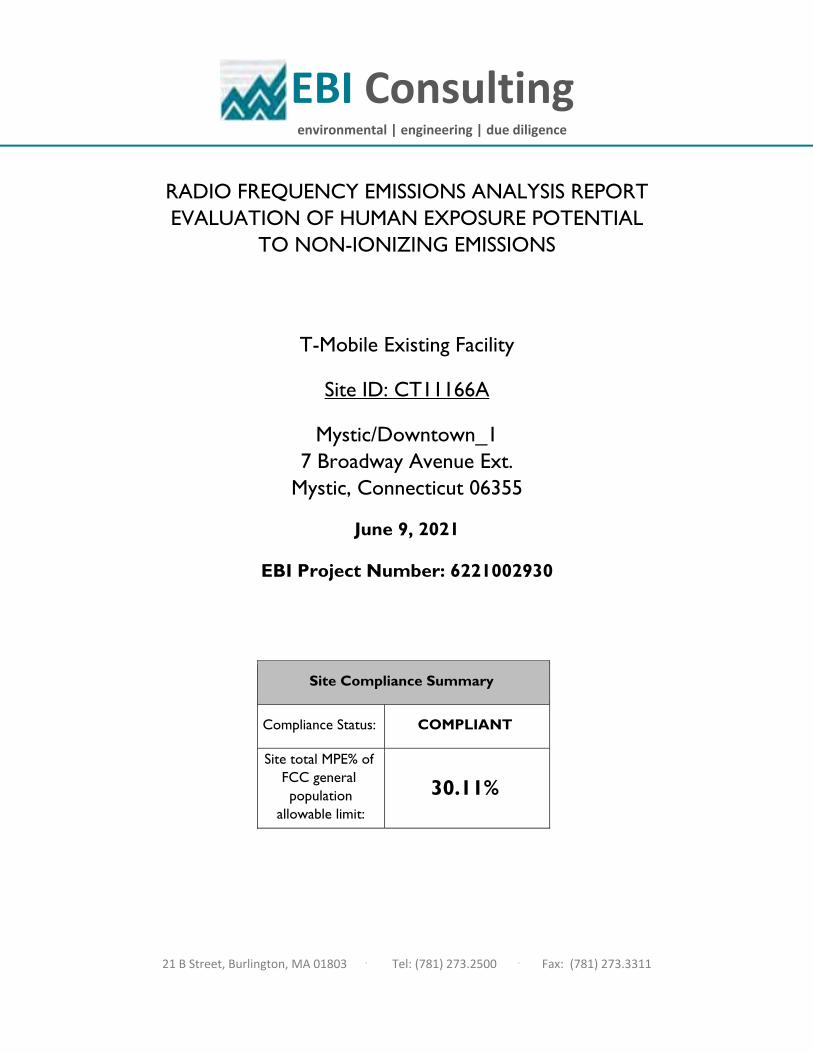
RADIO FREQUENCY EMISSIONS ANALYSIS REPORT
EVALUATION OF HUMAN EXPOSURE POTENTIAL
TO NON-IONIZING EMISSIONS
T-Mobile Existing Facility
Site ID: CT11166A
Mystic/Downtown_1
7 Broadway Avenue Ext. Mystic, Connecticut 06355
June 9, 2021
EBI Project Number: 6221002930
Site Compliance Summary
Compliance Status: COMPLIANT
Site total MPE% of FCC general population
allowable limit:
30.11%
EBI Consulting
environmental | engineering | due diligence
21 B Street, Burlington, MA 01803 . Tel: (781) 273.2500 . Fax: (781) 273.3311
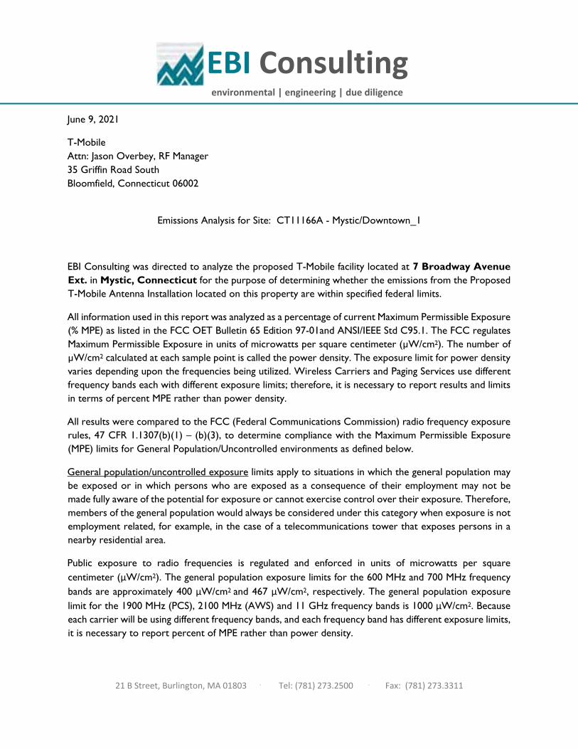
June 9, 2021
T-Mobile Attn: Jason Overbey, RF Manager 35 Griffin Road South Bloomfield, Connecticut 06002
Emissions Analysis for Site: CT11166A - Mystic/Downtown_1
EBI Consulting was directed to analyze the proposed T-Mobile facility located at 7 Broadway Avenue Ext. in Mystic, Connecticut for the purpose of determining whether the emissions from the Proposed T-Mobile Antenna Installation located on this property are within specified federal limits.
All information used in this report was analyzed as a percentage of current Maximum Permissible Exposure (% MPE) as listed in the FCC OET Bulletin 65 Edition 97-01and ANSI/IEEE Std C95.1. The FCC regulates Maximum Permissible Exposure in units of microwatts per square centimeter (µW/cm2). The number of µW/cm2 calculated at each sample point is called the power density. The exposure limit for power density varies depending upon the frequencies being utilized. Wireless Carriers and Paging Services use different frequency bands each with different exposure limits; therefore, it is necessary to report results and limits in terms of percent MPE rather than power density.
All results were compared to the FCC (Federal Communications Commission) radio frequency exposure rules, 47 CFR 1.1307(b)(1) – (b)(3), to determine compliance with the Maximum Permissible Exposure (MPE) limits for General Population/Uncontrolled environments as defined below.
General population/uncontrolled exposure limits apply to situations in which the general population may be exposed or in which persons who are exposed as a consequence of their employment may not be made fully aware of the potential for exposure or cannot exercise control over their exposure. Therefore, members of the general population would always be considered under this category when exposure is not employment related, for example, in the case of a telecommunications tower that exposes persons in a nearby residential area.
Public exposure to radio frequencies is regulated and enforced in units of microwatts per square centimeter (μW/cm2). The general population exposure limits for the 600 MHz and 700 MHz frequency bands are approximately 400 μW/cm2 and 467 μW/cm2, respectively. The general population exposure limit for the 1900 MHz (PCS), 2100 MHz (AWS) and 11 GHz frequency bands is 1000 μW/cm2. Because each carrier will be using different frequency bands, and each frequency band has different exposure limits, it is necessary to report percent of MPE rather than power density.
EBI Consulting
environmental | engineering | due diligence
21 B Street, Burlington, MA 01803 . Tel: (781) 273.2500 . Fax: (781) 273.3311
Occupational/controlled exposure limits apply to situations in which persons are exposed as a consequence of their employment and in which those persons who are exposed have been made fully aware of the potential for exposure and can exercise control over their exposure. Occupational/controlled exposure limits also apply where exposure is of a transient nature as a result of incidental passage through a location where exposure levels may be above general population/uncontrolled limits (see below), as long as the exposed person has been made fully aware of the potential for exposure and can exercise control over his or her exposure by leaving the area or by some other appropriate means.
Additional details can be found in FCC OET 65.
CALCULATIONS
Calculations were done for the proposed T-Mobile Wireless antenna facility located at 7 Broadway Avenue Ext. in Mystic, Connecticut using the equipment information listed below. All calculations were performed per the specifications under FCC OET 65. Since T-Mobile is proposing highly focused directional panel antennas, which project most of the emitted energy out toward the horizon, all calculations were performed assuming a lobe representing the maximum gain of the antenna per the antenna manufacturer’s supplied specifications, minus 10 dB for directional panel antennas and 20 dB for highly focused parabolic microwave dishes, was focused at the base of the tower. For this report, the sample point is the top of a 6-foot person standing at the base of the tower. For power density calculations, the broadcast footprint of the AIR6449 antenna has been considered. Due to the beamforming nature of this antenna, the actual beam locations vary depending on demand and are narrow in nature. Using the broadcast footprint accounts for the potential location of beams at any given time.
For all calculations, all equipment was calculated using the following assumptions:
1) 2 LTE channels (600 MHz Band) were considered for each sector of the proposed installation. These Channels have a transmit power of 30 Watts per Channel.
2) 1 NR channel (600 MHz Band) was considered for each sector of the proposed installation. This Channel has a transmit power of 80 Watts.
3) 2 LTE channels (700 MHz Band) were considered for each sector of the proposed installation.
These Channels have a transmit power of 30 Watts per Channel.
4) 4 GSM channels (PCS Band - 1900 MHz) were considered for each sector of the proposed installation. These Channels have a transmit power of 30 Watts per Channel.
5) 2 LTE channels (PCS Band - 1900 MHz) were considered for each sector of the proposed installation. These Channels have a transmit power of 60 Watts per Channel.
EBI Consulting
environmental | engineering | due diligence
21 B Street, Burlington, MA 01803 . Tel: (781) 273.2500 . Fax: (781) 273.3311
6) 2 LTE channels (AWS Band – 2100 MHz) were considered for each sector of the proposed installation. These Channels have a transmit power of 60 Watts per Channel.
7) 1 LTE Traffic channel (LTE 1C and 2C BRS Band - 2500 MHz) was considered for each sector of the proposed installation. This Channel has a transmit power of 60 Watts.
8) 1 LTE Broadcast channel (LTE 1C and 2C BRS Band - 2500 MHz) was considered for each
sector of the proposed installation. This Channel has a transmit power of 20 Watts. 9) 1 NR Traffic channel (BRS Band - 2500 MHz) was considered for each sector of the proposed
installation. This Channel has a transmit power of 120 Watts. 10) 1 NR Broadcast channel (BRS Band - 2500 MHz) was considered for each sector of the
proposed installation. This Channel has a transmit power of 40 Watts.
11) All radios at the proposed installation were considered to be running at full power and were uncombined in their RF transmissions paths per carrier prescribed configuration. Per FCC OET Bulletin No. 65 - Edition 97-01 recommendations to achieve the maximum anticipated value at each sample point, all power levels emitting from the proposed antenna installation are increased by a factor of 2.56 to account for possible in-phase reflections from the surrounding environment. This is rarely the case, and if so, is never continuous.
12) For the following calculations, the sample point was the top of a 6-foot person standing at the base of the tower. The maximum gain of the antenna per the antenna manufacturer’s supplied specifications, minus 10 dB for directional panel antennas and 20 dB for highly focused parabolic microwave dishes, was used in this direction. This value is a very conservative estimate as gain reductions for these particular antennas are typically much higher in this direction.
13) The antennas used in this modeling are the Ericsson AIR 6449 for the 2500 MHz / 2500 MHz
/ 2500 MHz / 2500 MHz channel(s), the RFS APXVAALL24_43-U-NA20 for the 600 MHz / 600 MHz / 700 MHz / 1900 MHz / 1900 MHz channel(s), the RFS APX16DWV-16DWV-S-E-A20 for the 2100 MHz channel(s) in Sector A, the Ericsson AIR 6449 for the 2500 MHz / 2500 MHz / 2500 MHz / 2500 MHz channel(s), the RFS APXVAALL24_43-U-NA20 for the 600 MHz / 600 MHz / 700 MHz / 1900 MHz / 1900 MHz channel(s), the RFS APX16DWV-16DWV-S-E-A20 for the 2100 MHz channel(s) in Sector B, the Ericsson AIR 6449 for the 2500 MHz / 2500 MHz / 2500 MHz / 2500 MHz channel(s), the RFS APXVAALL24_43-U-NA20 for the 600 MHz / 600 MHz / 700 MHz / 1900 MHz / 1900 MHz channel(s), the RFS APX16DWV-16DWV-S-E-A20 for the 2100 MHz channel(s) in Sector C. This is based on feedback from the carrier with regard to anticipated antenna selection. All Antenna gain values
EBI Consulting
environmental | engineering | due diligence
21 B Street, Burlington, MA 01803 . Tel: (781) 273.2500 . Fax: (781) 273.3311
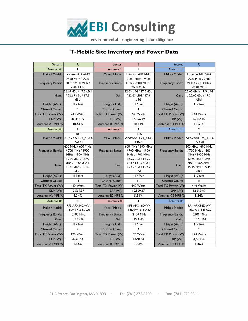
and associated transmit power levels are shown in the Site Inventory and Power Data table below. The maximum gain of the antenna per the antenna manufacturer’s supplied specifications, minus 10 dB for directional panel antennas and 20 dB for highly focused parabolic microwave dishes, was used for all calculations. This value is a very conservative estimate as gain reductions for these particular antennas are typically much higher in this direction.
14) The antenna mounting height centerline of the proposed antennas is 117 feet above ground level (AGL).
15) Emissions values for additional carriers were taken from the Connecticut Siting Council active database. Values in this database are provided by the individual carriers themselves.
16) All calculations were done with respect to uncontrolled / general population threshold limits.
EBI Consulting
environmental | engineering | due diligence
21 B Street, Burlington, MA 01803 . Tel: (781) 273.2500 . Fax: (781) 273.3311
T-Mobile Site Inventory and Power Data
Sector: A Sector: B Sector: C Antenna #: 1 Antenna #: 1 Antenna #: 1
Make / Model: Ericsson AIR 6449 Make / Model: Ericsson AIR 6449 Make / Model: Ericsson AIR 6449
Frequency Bands: 2500 MHz / 2500 MHz / 2500 MHz /
2500 MHz Frequency Bands:
2500 MHz / 2500 MHz / 2500 MHz /
2500 MHz Frequency Bands:
2500 MHz / 2500 MHz / 2500 MHz /
2500 MHz
Gain: 22.65 dBd / 17.3 dBd
/ 22.65 dBd / 17.3 dBd
Gain: 22.65 dBd / 17.3 dBd
/ 22.65 dBd / 17.3 dBd
Gain: 22.65 dBd / 17.3 dBd
/ 22.65 dBd / 17.3 dBd
Height (AGL): 117 feet Height (AGL): 117 feet Height (AGL): 117 feet Channel Count: 4 Channel Count: 4 Channel Count: 4
Total TX Power (W): 240 Watts Total TX Power (W): 240 Watts Total TX Power (W): 240 Watts ERP (W): 36,356.09 ERP (W): 36,356.09 ERP (W): 36,356.09
Antenna A1 MPE %: 10.61% Antenna B1 MPE %: 10.61% Antenna C1 MPE %: 10.61% Antenna #: 2 Antenna #: 2 Antenna #: 2
Make / Model: RFS
APXVAALL24_43-U-NA20
Make / Model: RFS
APXVAALL24_43-U-NA20
Make / Model: RFS
APXVAALL24_43-U-NA20
Frequency Bands: 600 MHz / 600 MHz
/ 700 MHz / 1900 MHz / 1900 MHz
Frequency Bands: 600 MHz / 600 MHz
/ 700 MHz / 1900 MHz / 1900 MHz
Frequency Bands: 600 MHz / 600 MHz
/ 700 MHz / 1900 MHz / 1900 MHz
Gain: 12.95 dBd / 12.95 dBd / 13.65 dBd / 15.45 dBd / 15.45
dBd Gain:
12.95 dBd / 12.95 dBd / 13.65 dBd / 15.45 dBd / 15.45
dBd Gain:
12.95 dBd / 12.95 dBd / 13.65 dBd / 15.45 dBd / 15.45
dBd Height (AGL): 117 feet Height (AGL): 117 feet Height (AGL): 117 feet
Channel Count: 11 Channel Count: 11 Channel Count: 11 Total TX Power (W): 440 Watts Total TX Power (W): 440 Watts Total TX Power (W): 440 Watts
ERP (W): 12,569.87 ERP (W): 12,569.87 ERP (W): 12,569.87 Antenna A2 MPE %: 5.34% Antenna B2 MPE %: 5.34% Antenna C2 MPE %: 5.34%
Antenna #: 3 Antenna #: 3 Antenna #: 3
Make / Model: RFS APX16DWV-16DWV-S-E-A20 Make / Model: RFS APX16DWV-
16DWV-S-E-A20 Make / Model: RFS APX16DWV-16DWV-S-E-A20
Frequency Bands: 2100 MHz Frequency Bands: 2100 MHz Frequency Bands: 2100 MHz
Gain: 15.9 dBd Gain: 15.9 dBd Gain: 15.9 dBd Height (AGL): 117 feet Height (AGL): 117 feet Height (AGL): 117 feet
Channel Count: 2 Channel Count: 2 Channel Count: 2 Total TX Power (W): 120 Watts Total TX Power (W): 120 Watts Total TX Power (W): 120 Watts
ERP (W): 4,668.54 ERP (W): 4,668.54 ERP (W): 4,668.54 Antenna A3 MPE %: 1.36% Antenna B3 MPE %: 1.36% Antenna C3 MPE %: 1.36%
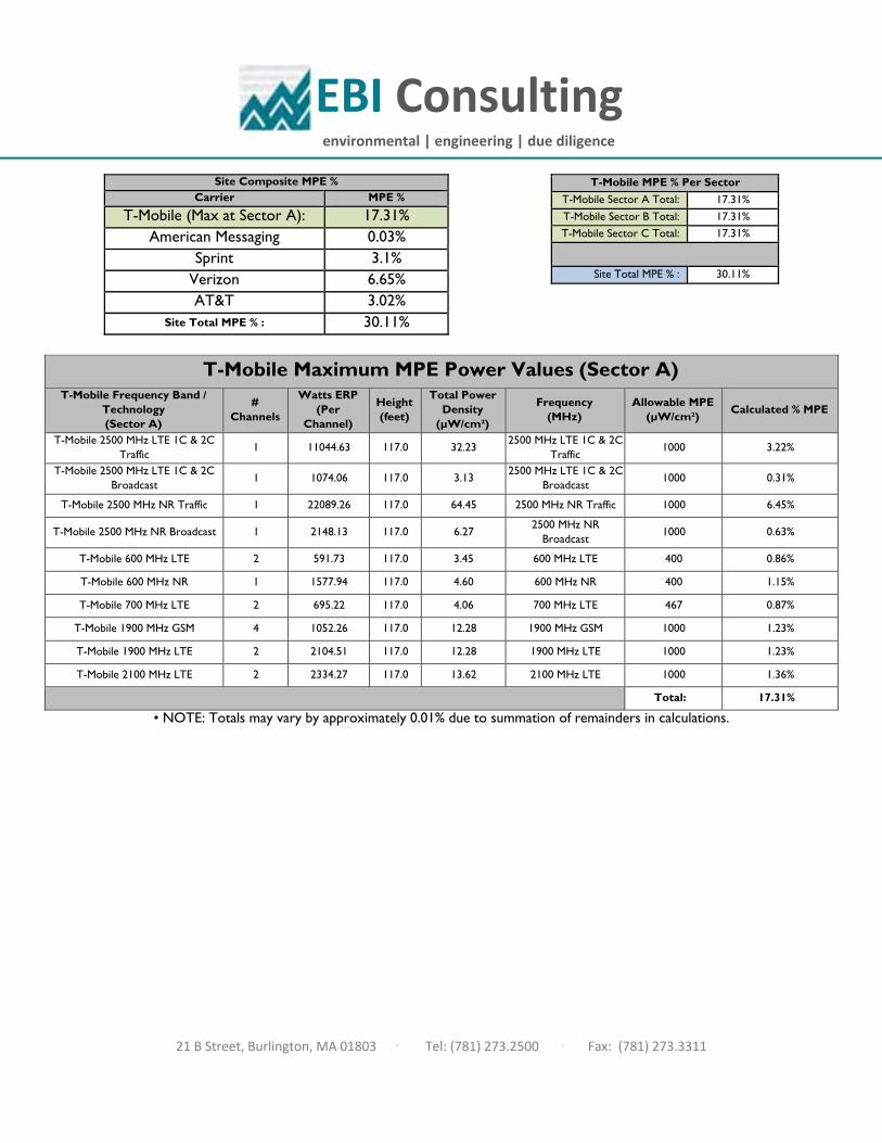
EBI Consulting
environmental | engineering | due diligence
21 B Street, Burlington, MA 01803 . Tel: (781) 273.2500 . Fax: (781) 273.3311
Site Composite MPE % Carrier MPE %
T-Mobile (Max at Sector A): 17.31% American Messaging 0.03%
Sprint 3.1% Verizon 6.65% AT&T 3.02%
Site Total MPE % : 30.11%
T-Mobile MPE % Per Sector
T-Mobile Sector A Total: 17.31% T-Mobile Sector B Total: 17.31% T-Mobile Sector C Total: 17.31%
Site Total MPE % : 30.11%
• NOTE: Totals may vary by approximately 0.01% due to summation of remainders in calculations.
T-Mobile Maximum MPE Power Values (Sector A)
T-Mobile Frequency Band / Technology (Sector A)
# Channels
Watts ERP (Per
Channel)
Height (feet)
Total Power Density
(µW/cm²)
Frequency (MHz)
Allowable MPE (µW/cm²)
Calculated % MPE
T-Mobile 2500 MHz LTE 1C & 2C Traffic
1 11044.63 117.0 32.23 2500 MHz LTE 1C & 2C
Traffic 1000 3.22%
T-Mobile 2500 MHz LTE 1C & 2C Broadcast
1 1074.06 117.0 3.13 2500 MHz LTE 1C & 2C
Broadcast 1000 0.31%
T-Mobile 2500 MHz NR Traffic 1 22089.26 117.0 64.45 2500 MHz NR Traffic 1000 6.45%
T-Mobile 2500 MHz NR Broadcast 1 2148.13 117.0 6.27 2500 MHz NR
Broadcast 1000 0.63%
T-Mobile 600 MHz LTE 2 591.73 117.0 3.45 600 MHz LTE 400 0.86%
T-Mobile 600 MHz NR 1 1577.94 117.0 4.60 600 MHz NR 400 1.15%
T-Mobile 700 MHz LTE 2 695.22 117.0 4.06 700 MHz LTE 467 0.87%
T-Mobile 1900 MHz GSM 4 1052.26 117.0 12.28 1900 MHz GSM 1000 1.23%
T-Mobile 1900 MHz LTE 2 2104.51 117.0 12.28 1900 MHz LTE 1000 1.23%
T-Mobile 2100 MHz LTE 2 2334.27 117.0 13.62 2100 MHz LTE 1000 1.36%
Total: 17.31%

EBI Consulting
environmental | engineering | due diligence
21 B Street, Burlington, MA 01803 . Tel: (781) 273.2500 . Fax: (781) 273.3311
Summary
All calculations performed for this analysis yielded results that were within the allowable limits for general population exposure to RF Emissions.
The anticipated maximum composite contributions from the T-Mobile facility as well as the site composite emissions value with regards to compliance with FCC’s allowable limits for general population exposure to RF Emissions are shown here:
T-Mobile Sector Power Density Value (%) Sector A: 17.31% Sector B: 17.31% Sector C: 17.31%
T-Mobile Maximum MPE % (Sector A):
17.31%
Site Total: 30.11%
Site Compliance Status: COMPLIANT
The anticipated composite MPE value for this site assuming all carriers present is 30.11% of the allowable FCC established general population limit sampled at the ground level. This is based upon values listed in the Connecticut Siting Council database for existing carrier emissions.
FCC guidelines state that if a site is found to be out of compliance (over allowable thresholds), that carriers over a 5% contribution to the composite value will require measures to bring the site into compliance. For this facility, the composite values calculated were well within the allowable 100% threshold standard per the federal government.