final report of geotechnical exploration for jea district
TRANSCRIPT

Final Report of Geotechnical Exploration For
JEA District 2 Pump Station and Flow Rerouting
MAE Project No. 0011-0017 November 5, 2018
Prepared for:
8381 Dix Ellis Trail, Suite 400
Jacksonville, FL 32256
Prepared by:
8936 Western Way, Suite 12 Jacksonville, Florida 32256
Phone (904) 519-6990 Fax (904) 519-6992

8936 Western Way, Suite 12, Jacksonville, Florida 32256 p. 904.519.6990
www.MeskelEngineering.com
November 5, 2018 CDM Smith, Inc. 8381 Dix Ellis Trail, Suite 400 Jacksonville, FL 32256 Attention: Mr. Yanni Polematidis, P.E. Reference: Final Report of Geotechnical Exploration
JEA District 2 Pump Station and Flow Rerouting Jacksonville, Florida MAE Project No. 0011-0017
Dear Mr. Polematidis: Meskel & Associates Engineering, PLLC (MAE) has completed a geotechnical exploration for the subject project. Our work was performed in general accordance with our revised proposal dated September 14, 2017. The geotechnical exploration was performed to evaluate the general subsurface conditions within the areas of the three proposed pump station locations (Robena Road, Pulaski Road, and Harts Road), and to provide recommendations for foundation support and design, pond design, and site preparation. This report has been revised from its original version dated June 21, 2018 to include comments received from CDM Smith.
Provided the sites are prepared with the recommendations included in this report, it is our opinion that the proposed pump stations at Pulaski Road and Robena Road, and the proposed Electrical Building at Harts Road, can be supported on conventional shallow foundation systems.
We appreciate this opportunity to be of service as your geotechnical consultant on this phase of the project. If you have any questions, or if we may be of any further service, please contact us.
Sincerely, MESKEL & ASSOCIATES ENGINEERING, PLLC MAE FL Certificate of Authorization No. 28142 _______________________________________ _______________________________________ W. Josh Mele, E.I. P. Rodney Mank, P.E. Staff Engineer Principal Engineer Licensed, Florida No. 41986
Distribution: Mr. Yanni Polematidis, P.E. – CDM Smith, Inc. 1 pdf

JEA District 2 Pump Station and Flow Rerouting - FINAL MAE Project No. 0011-0017
Page | i
TABLE OF CONTENTS 1.0 PROJECT INFORMATION ................................................................................................... 1
1.1 General .................................................................................................................................. 1 1.2 Project Description ................................................................................................................ 1 1.3 Site Conditions ....................................................................................................................... 1
2.0 FIELD EXPLORATION ......................................................................................................... 2 2.1 SPT Borings ............................................................................................................................ 2
3.0 LABORATORY TESTING ..................................................................................................... 2 3.1 Visual Classification ............................................................................................................... 2 3.2 Index Tests ............................................................................................................................. 3 3.3 Corrosion Series Tests ........................................................................................................... 3
4.0 GENERAL SUBSURFACE CONDITIONS ................................................................................ 3 4.1 General Soil Profile ................................................................................................................ 3 4.2 Groundwater Level ................................................................................................................ 4 4.3 Review of the USDA Web Soil Survey Map ........................................................................... 4 4.4 Seasonal High Groundwater Level ......................................................................................... 5
5.0 ROBENA ROAD FOUNDATION DESIGN RECOMMENDATIONS ............................................ 5 5.1 General .................................................................................................................................. 5 5.2 Pump Station Foundation Recommendations ...................................................................... 5 5.3 Electrical Building Foundation Design Recommendations .................................................... 6 5.4 Settlement Estimates ............................................................................................................ 7 5.5 Pavement Considerations ...................................................................................................... 7 5.6 Below Grade Structures Design Recommendations .............................................................. 8 5.7 Reuse of Onsite Soils ............................................................................................................. 9 5.8 Environmental Classification ............................................................................................... 10
6.0 PULASKI ROAD DESIGN RECOMMENDATIONS ................................................................. 10 6.1 General ................................................................................................................................ 10 6.2 Pump Station Foundations Recommendations ................................................................... 10 6.3 Electrical Building Foundation Design Recommendations .................................................. 11 6.4 Settlement Estimates .......................................................................................................... 12 6.5 Pavement Considerations .................................................................................................... 12 6.6 Below Grade Structures Design Recommendations ............................................................ 13 6.7 Reuse of Onsite Soils ........................................................................................................... 14 6.8 Environmental Classification ............................................................................................... 14
7.0 HARTS ROAD DESIGN RECOMMENDATIONS ................................................................... 14 7.1 General ................................................................................................................................ 14 7.2 Electrical Building Foundation Design Recommendations .................................................. 15 7.3 Settlement Estimates .......................................................................................................... 15 7.4 Reuse of Onsite Soils ........................................................................................................... 16

JEA District 2 Pump Station and Flow Rerouting - FINAL MAE Project No. 0011-0017
Page | ii
8.0 SITE SEISMIC CLASSIFICATION......................................................................................... 16 9.0 SITE PREPARATION AND EARTHWORK RECOMMENDATIONS .......................................... 17
9.1 Clearing and Stripping ......................................................................................................... 17 9.2 Temporary Groundwater Control ........................................................................................ 17 9.3 Surface Compaction ............................................................................................................ 18 9.4 Preparation of Pipe Bedding Soils ....................................................................................... 18 9.5 Compaction of Excavation Bottom, Pipe Bedding and Backfilling ...................................... 18 9.6 Structural Backfill and Fill Soils ............................................................................................ 19 9.7 Foundation Areas ................................................................................................................ 20 9.8 Pavement Areas ................................................................................................................... 20 9.9 Excavation Protection .......................................................................................................... 20
10.0 QUALITY CONTROL TESTING ........................................................................................... 20 11.0 REPORT LIMITATIONS .................................................................................................... 20
FIGURES
Figures 1A-1C. Site Location Map Figures 2A-2C. Boring Location Plan Figures 3-7. Generalized Soil Profiles
APPENDICES
Appendix A. Soil Boring Logs Field Exploration Procedures Key to Boring Logs Key to Soil Classification Appendix B. Summary of Laboratory Test Results Laboratory Test Procedures
Appendix C. Summary of Corrosivity Test Results

JEA District 2 Pump Station and Flow Rerouting - FINAL MAE Project No. 0011-0017
Page | 1
1.0 PROJECT INFORMATION 1.1 General Project information was provided to us by Mr. Yanni Polematidis, P.E., with CDM Smith, Inc. For our review and reference, we were provided with the following JEA Cedar Bay (District II) Pumping Stations and Flow Rerouting Project documents:
• Figures 1 and 2, Robena Road Pump Station - Existing Site Survey and Yard Piping Plan, Sheets C-1 and C-2 (respectively); developed by CDM Smith, dated August 2017.
• Figures 3 and 4, Pulaski Road Pump Station - Existing Site Survey and Yard Piping Plan, Sheets C-3 and C-4 (respectively); developed by CDM Smith, dated August 2017.
• Figure 5, Harts Road Pump Station - Site Layout, Sheet C-5; developed by CDM Smith, dated June 2017.
1.2 Project Description The sites for the subject project are located in Jacksonville, Florida. The general site locations are shown on Figures 1A through 1C.
Based on the provided information and our discussions with Mr. Polematidis, it is our understanding the proposed project includes the construction of two new pumping stations, one south of Robena Road near its intersection with Verde Gardens Road, and the other east of Pulaski Road just north of its intersection with Noah Road, and a new electrical building at the existing Harts Road Pump Station site. The new pumping stations will each include a submersible booster pump station with three primary pumps (2 duty and 1 standby) and two jockey pumps (1 duty and 1 standby), an electrical building, generator, fuel tank, a stormwater management pond, and associated drive and parking areas. We have assumed that the depth of the wet wells will be 15 to 20 feet below existing grades. In addition, the proposed force main piping at the two planned pump stations will be 20-inch polyvinyl chloride (PVC) pipe.
From our observation of the provided plans, we understand the proposed electrical buildings will be prefabricated metal buildings, each approximately 27 feet by 12 feet in “footprint” plan dimensions and supported on a monolithic, turned-down-edge slab-on-grade. Although detailed information has not been provided, we have assumed the wall and floor loads will not exceed 2 kips per linear foot (klf) and 100 pounds per square foot (psf), respectively. Furthermore, we except the planned generators and fuel tanks will be supported on monolithic slab-on-grade foundations. Grading plans were not provided at the time of our evaluation; however, we have assumed the building and pavement areas will be supported on less than 2 to 3 feet of fill above the presently existing ground surface.
If actual project information varies from these conditions, then the recommendations in this report may need to be re-evaluated. Any changes in these conditions should be provided so the need for re-evaluation of our recommendations can be assessed prior to final design.
1.3 Site Conditions Prior to the start of this project, a site visit was conducted at the Pulaski Road and Robena Road sites by our field crew on September 13, 2017. Recent rains had caused both sites to be flooded, particularly within the wetland areas as designated on the site plans, thus causing them to be inaccessible with our

JEA District 2 Pump Station and Flow Rerouting - FINAL MAE Project No. 0011-0017
Page | 2
All-Terrain Vehicle (ATV) drilling equipment. Our previous experience with similar site conditions has shown that saturated surficial sandy soils will rut while traversing the site, thus causing our ATV to get stuck. Therefore, it was decided that both sites would be accessed using our portable, tripod-mounted, drilling equipment. This equipment would be carried to each boring location and setup on pallets to stabilize the tripod.
At the time of our field exploration at the Robena Road site (October 2017), it was observed that much of the site was still covered with standing water. Groundwater levels at the boring locations were at the ground surface. This resulted in soft surficial soil conditions. Most of the site was heavily wooded as well.
The Pulaski Road site did not contain many areas of standing water at the time of our field exploration (April 2018). However, the surface soils were generally wet, soft, organic topsoils that were difficult to travel across. This site was also mostly heavily wooded.
2.0 FIELD EXPLORATION Three separate field explorations were performed for this project; one for each site. The Harts Road Pump Station exploration was performed on August 17, 2017, the Robena Road site was explored during the period of October 10 through 12, 2017, and the Pulaski Road site was explored during the period of April 5 through 13, 2018. Copies of the plans provided to us, which show the approximate boring locations, are included as the Boring Location Plan, Figures 2A through 2C. The boring locations were provided by you, and then GPS coordinates were obtained by overlaying the provided plans in Google Earth. Our field personnel then located each boring location using a Garmin GPSMAP 78 hand-held GPS receiver; therefore, the boring locations should be considered accurate only to the degree implied by the method of measurement used.
2.1 SPT Borings To explore the subsurface conditions within the areas of the proposed Pump Stations at Robena Road and Pulaski Road, and the Electrical Building at the Harts Road site, we located and performed 11 Standard Penetration Test (SPT) borings, each drilled to depths of approximately 15, 25 and 35 feet below the existing ground surface. Our truck mounted CME 55 drill rig was used to perform the Harts Road boring; However, due to the saturated soil conditions as described in Section 1.3 above, the Robena Road site was accessed using our portable, tripod-mounted drilling equipment. This equipment was carried to each location and set up on pallets for stabilization. In addition, due to the dense tree vegetation at the Pulaski Road site, the boring locations were accessed using our ATV-mounted CME 45. All the borings were performed in general accordance with the methodology outlined in ASTM D 1586. Split-spoon soil samples recovered during performance of the borings were visually described in the field and representative portions of the samples were transported to our laboratory for further evaluation.
3.0 LABORATORY TESTING 3.1 Visual Classification Representative soil samples obtained during our field exploration were visually classified by a geotechnical engineer using the Unified Soil Classification System (USCS) in general accordance with ASTM D 2488. A Key to the Soil Classification System is included in Appendix A.

JEA District 2 Pump Station and Flow Rerouting - FINAL MAE Project No. 0011-0017
Page | 3
3.2 Index Tests Quantitative laboratory testing was performed on selected samples of the soils encountered during the field exploration to better define the composition of the soils encountered and to provide data for correlation to their anticipated strength and compressibility characteristics. The laboratory testing determined the Atterberg limits, natural moisture, percent passing a Number 200 U.S. sieve (percent fines), and organic contents of selected soil samples. The results of the laboratory testing are shown in the Summary of Laboratory Test Results included in Appendix B. Also, these results are shown on the Generalized Soil Profiles on Figures 3 through 7, and on the Log of Boring records at the respective depths from which the tested samples were recovered.
3.3 Corrosion Series Tests Composite soil samples from the Robena Road and Pulaski Road sites were selected for corrosion potential testing. These samples were obtained from borings located near the proposed Booster Pump Stations (B-3 and B-8) at depths from 2 to 8 feet below the existing ground surface. The testing included soil pH, resistivity, and chloride and sulfate contents. The test results are discussed in Section 5.8 and Section 6.8 below, and are presented on the Summary of Laboratory Corrosivity Tests Results in Appendix C.
4.0 GENERAL SUBSURFACE CONDITIONS 4.1 General Soil Profile Graphical presentation of the generalized subsurface conditions is presented on Figures 3 through 7. Detailed boring records are included in Appendix A. When reviewing these records, it should be understood that the soil conditions will vary between the boring locations.
4.1.1 Robena Road
In general, the borings encountered very loose fine sands with silt (SP-SM) containing few to some amounts of organic fines to a depth of about 2 to 6 feet, underlain by loose to dense clayey fine sands (SC) and silty fine sands (SM) to depths ranging from about 13.5 feet to 18.5 feet. Following these sandy soils, the borings encountered soft to stiff clays (CL, CH) continuing to depths ranging from 22 feet to 33.5 feet, underlain by clayey fine sands (SC) and silty fine sands (SM) to their termination depths of up to approximately 35 feet below the existing ground surface.
4.1.2 Pulaski Road
In general, the borings encountered a surficial layer of organic material (e.g., pine needles, small root clusters, moss, etc.) 8 to 9 inches thick, underlain by fine sands (SP), fine sands with silt (SP-SM) and silty fine sands (SM) to their termination depths of up to 35 feet below the existing ground surface. The relative densities of the soils encountered ranged from very loose to very dense and typically increased with depth. The near surface soils often contained trace amounts of root fragments and organic fines, and soils containing trace clay constituents were frequently encountered throughout the depths explored.
4.1.3 Harts Road
In general, the boring encountered a surficial topsoil layer 6 inches thick, underlain by loose fine sand with

JEA District 2 Pump Station and Flow Rerouting - FINAL MAE Project No. 0011-0017
Page | 4
silt (SP-SM) containing trace clay nodules to a depth of about 2 feet, followed by medium dense to loose clayey fine sands (SC) to a depth of about 13.5 feet. Following these clayey sand soils, the boring encountered medium dense silty fine sands (SM) and fine sands with silt (SP-SM) to a depth of about 24.5 feet, underlain by very loose (weight-of-hammer) clayey fine sands to a depth of about 28.5 feet. Following the very loose clayey sand soils, the boring encountered loose silty fine sands (SM) to a depth of about 34.5 feet and then terminated in medium dense clayey fine sands (SC) at a depth of approximately 35 feet below the existing ground surface.
4.2 Groundwater Level The groundwater level was encountered at each of the boring locations and recorded at the time of drilling. The table below shows the variation in depths below the existing ground surface at each site. However, it should be anticipated that the groundwater levels will fluctuate seasonally and with changes in climate. As such, we recommend that the water table be re-measured prior to construction. Measured groundwater levels are shown the boring profiles and boring logs.
Project Site Variation in Depths Below the Existing Ground Surface Robena Road At existing ground surface Pulaski Road 1 foot to 2 feet 8 inches Harts Road 11 inches
4.3 Review of the USDA Web Soil Survey Map The results of a review of the USDA Soil Survey Conservation Service (SSCS) Web Soil Survey of Duval County are shown in the table below. The soil drainage class, hydrological group, and estimated seasonal high groundwater levels reported in the Soil Survey are as follows:
Project Site Map Unit
Symbol Map Unit Name Drainage Class
Hydrologic Group
Depth to the Water
Table(1) (inches)
Robena Road 51 Pelham fine sand, 0 to 2
percent slopes Poorly Drained B/D 6 to 12
Robena Road 66 Surrency loamy fine sand,
depressional, 0 to 2 percent slopes
Very Poorly Drained
B/D 0
Pulaski Road 63 Sapelo fine sand, 0 to 2
percent slopes Poorly Drained B/D 8 to 18
Harts Road 74 Pelham-Urban land complex,
0 to 2 percent slopes Poorly Drained B/D 0 to 12
(1) The “Water Table” above refers to a saturated zone in the soil which occurs during specified months, typically the summer wet season. Estimates of the upper limit shown in the Web Soil Survey are based mainly on observations

JEA District 2 Pump Station and Flow Rerouting - FINAL MAE Project No. 0011-0017
Page | 5
of the water table at selected sites and on evidence of a saturated zone, namely grayish colors (redoximorphic features) in the soil. A saturated zone that lasts for less than a month is not considered a water table. (2) The term “complex”, as defined by the USDA, refers to a map unit consisting of two or more soils or miscellaneous areas in such an intricate pattern or in such small areas that they cannot be shown separately on the map.
4.4 Seasonal High Groundwater Level In estimating seasonal high groundwater level, a number of factors are taken into consideration including antecedent rainfall, soil redoximorphic features (i.e., soil mottling), stratigraphy (including presence of hydraulically restrictive layers), vegetative indicators, effects of development, and relief points such as drainage ditches, low-lying areas, etc.
Based on our observation of the site conditions over time, and our interpretation of the boring logs and review of published data, we estimate the seasonal high groundwater levels at all three sites to be at the existing ground surface. However, the drainage engineer should be consulted to determine if higher groundwater levels are likely due to offsite drainage patterns that may be influencing the groundwater levels at these sites.
For all three sites, it is possible that higher groundwater levels may exceed the estimated seasonal high groundwater level as a result of significant or prolonged rains. Therefore, we recommend that design drawings and specifications account for the possibility of groundwater level variations, and construction planning should be based on the assumption that such variations will occur.
5.0 ROBENA ROAD FOUNDATION DESIGN RECOMMENDATIONS 5.1 General The following evaluation and recommendations are based on the provided project information as presented in this report, the results of the field exploration and laboratory testing performed, and the construction techniques recommended in Section 9.0 below. If the described project conditions are incorrect or changed after this report, or if subsurface conditions encountered during construction are different from those reported, MAE should be notified so these recommendations can be re-evaluated and revised, if necessary. We recommend that MAE review the foundation plans and earthwork specifications to verify that the recommendations in this report have been properly interpreted and implemented.
5.2 Pump Station Foundation Recommendations
Based on the results of our exploration, we consider the subsurface conditions at the site adaptable for support of the proposed pump station equipment on monolithic slab-on-grade designed for a modulus of subgrade reaction of 200 pci, provided that the surficial topsoil is removed from within the construction area and replaced with suitable fill material as outlined in Section 9.0.
5.2.1 Bearing Pressure
The maximum allowable net soil bearing pressure for use in monolithic slab-on-grade design should not exceed 2,000 psf. Due to the clay layers encountered between depths of approximately 13.5 feet to up to 34 feet, the maximum allowable net soil bearing pressure for the wet well base slab should not exceed 500 psf. Net bearing pressure is defined as the soil bearing pressure at the foundation bearing level in

JEA District 2 Pump Station and Flow Rerouting - FINAL MAE Project No. 0011-0017
Page | 6
excess of the effective overburden pressure at that level. The slab-on-grade and wet well base slab foundations should be designed based on the maximum load that could be imposed by all loading conditions.
5.2.2 Bearing Depth
The turned down edges of the monolithic slabs-on-grade supporting surface equipment should bear at a depth of at least 12 inches below the exterior final grades. It is recommended that stormwater be diverted away from these slabs to reduce the possibility of erosion beneath the slabs.
5.2.3 Bearing Material
The subgrade soils below the monolithic slabs-on-grades or the wet well slabs should consist of suitable on-site or import structural fill soils. The fine sands (SP) and fine sands with silt (SP-SM) as encountered in the borings are considered suitable onsite soils. These soils should be compacted to at least 95 percent of the soil’s modified Proctor Maximum Dry Density (ASTM D-1557) to a depth of at least one foot below the slab bearing levels. Control of the soil’s moisture content, particularly for the subgrade soils below the wet well slab, will be necessary to achieve the required level of compaction.
The clay (CL, CH) soils as encountered at the boring locations are not considered suitable bearing soils for the wet well slab. These soils should be excavated to a depth of at least 12 inches below the planned bearing depth and within the full lateral extent of the slab, plus a margin of 3 feet outside the limits of the slab. We recommend the clay soils at the bottom of the excavation be overlain by a filter fabric to act as a separation layer between the clay soils and the subgrade backfill. The fabric should continue up the sides of the excavation to separate the soil backfill from the adjacent clay soils. The excavated clays at the subgrade level should be replaced with a graded aggregate such as ASTM C33 Gradation 67 stone as specified in the JEA Water/Wastewater Standards, as discussed in Section 9.5 below.
5.3 Electrical Building Foundation Design Recommendations Based on the results of our exploration, we consider the subsurface conditions at the site adaptable for support of the proposed structure when constructed on a properly designed shallow foundation system. Provided the site preparation and earthwork construction recommendations outlined in Section 9.0 of this report are performed, the following parameters may be used for foundation design.
5.3.1 Bearing Pressure
The maximum allowable net soil bearing pressure to be applied to the foundations subgrade soils by the turned-down edge footings of the monolithic slab should not exceed 2,500 psf. Net bearing pressure is defined as the soil bearing pressure at the foundation bearing level in excess of the effective overburden pressure at that level. The foundations should be designed based on the maximum load that could be imposed by all loading conditions.
5.3.2 Bearing Depth
The turned down edges of the monolithic slabs-on-grade supporting surface equipment should bear at a depth of at least 12 inches below the exterior final grades. It is recommended that stormwater be diverted away from these slabs to reduce the possibility of erosion beneath the slabs.

JEA District 2 Pump Station and Flow Rerouting - FINAL MAE Project No. 0011-0017
Page | 7
5.3.3 Bearing Material
The foundations may bear in either the compacted suitable natural soils or compacted structural fill. The bearing level soils, after compaction, should exhibit densities equivalent to 95 percent of the modified Proctor maximum dry density (ASTM D 1557), to a depth of at least one foot below the foundation bearing levels.
5.3.4 Floor Slab
The floor slab for the electrical building can be constructed as a slab-on-ground designed for a modulus of subgrade reaction of 200 pci, provided unsuitable material is removed and replaced with compacted structural fill as outlined in Section 9.0. It is recommended that the floor slab bearing soils be covered with an impervious membrane to reduce moisture entry and floor dampness. A 6-mil thick plastic membrane is commonly used for this purpose. Care should be exercised not to tear large sections of the membrane during placement of reinforcing steel and concrete. In addition, we recommend that a minimum separation of 2 feet be maintained between the finished floor levels and the estimated normal seasonal high groundwater level.
5.4 Settlement Estimates Post-construction settlements of the structure will be influenced by several interrelated factors, such as (1) subsurface stratification and strength/compressibility characteristics; (2) footing size, bearing level, applied loads, and resulting bearing pressures beneath the foundations; and (3) site preparation and earthwork construction techniques used by the contractor. Our settlement estimates for the structure are based on the use of site preparation/earthwork construction techniques as recommended in Section 9.0 of this report. Any deviation from these recommendations could result in an increase in the estimated post-construction settlements of the structure.
Due to the sandy nature of the near-surface soils, we expect the majority of settlement to occur in an elastic manner and fairly rapidly during construction. Using the recommended maximum bearing pressure, the supplied/assumed maximum structural loads, and the field and laboratory test data that we have correlated to geotechnical strength and compressibility characteristics of the subsurface soils, we estimate that total settlements of the structure could be on the order of one inch or less.
Differential settlements result from differences in applied bearing pressures and variations in the compressibility characteristics of the subsurface soils. Because of the general uniformity of the subsurface conditions and the recommended site preparation and earthwork construction techniques outlined in Section 9.0, we estimate differential settlement of the structure to be on the order of one-half inch or less.
5.5 Pavement Considerations Based on the results of our exploration, we consider the subsurface conditions at the site favorable for support of a flexible pavement section, when constructed on properly prepared subgrade soils as outlined in Section 9.0 of this report. Pavement design and construction should conform to the City of Jacksonville Standard Asphaltic Concrete Driveway, Plate P-204, for a Class II Commercial driveway.
5.5.1 Wearing Surface
The wearing surface should consist of Florida Department of Transportation (FDOT) Type S asphaltic concrete having a minimum Marshall Stability of 1,500 lbs. Concrete pavement should have a minimum

JEA District 2 Pump Station and Flow Rerouting - FINAL MAE Project No. 0011-0017
Page | 8
28-day strength of 3,000 psi. Specific requirements for Type S asphaltic concrete wearing surface are outlined in the latest edition of the Florida Department of Transportation, Standard Specifications for Road and Bridge Construction.
5.5.2 Base and Subgrade
Due to the typical soil saturation and wetland areas at the project site, it is unlikely that an appropriate separation between a limerock base course and the estimated seasonal high groundwater table will be able to be maintained. As an alternative to the more partly soluble limerock material, a Graded Aggregate Base (GAB) such as crushed concrete may be used. The GAB should meet FDOT criteria or be from a FDOT-certified source and compacted to the same level as would a limerock material.
The subgrade material should have a minimum LBR of 40 and be compacted to 98 percent of the modified Proctor maximum dry density (AASHTO T-180) value.
5.5.3 Underdrains
Satisfactory pavement life is dependent on dry/strong pavement support provided by the base and subgrade courses. Accordingly, a minimum clearance of 2 feet must be maintained between the estimated seasonal high groundwater table and the bottom of the limerock base layer, or 2.5 feet below the pavement surface. If a GAB is used as the base material, then the minimum clearances may be reduced to one foot and 1.5 feet, respectively. Depending on final pavement grades, subsurface drains may be required to maintain dry base and subgrade materials. Once the final paving and drainage plans are prepared, we would be pleased to review them and the need for underdrains.
5.6 Below Grade Structures Design Recommendations Based on the results of the subsurface explorations, laboratory testing, and provided information, as included in this report, we consider the subsurface conditions at the site adaptable for supporting the proposed PVC pipeline and pump station wet well when constructed upon properly prepared subgrade soils.
As noted in Section 4.0 above, clays (CL, CH) were encountered at some boring locations within the expected bearing level of the planned wet well slabs. Due to the plasticity of these soils and their affinity for moisture, we consider these soils unsuitable for use as bedding and backfill material for the associated piping and wet well structures. We recommend that the clay soils at the bearing depth be overexcavated a minimum of 12 inches below the planned bearing depth and within the full lateral extent of the pipeline or structure slab plus a margin of 3 feet. The clay soils at the bottom of the excavation should be overlain by a filter fabric material to act as a separation layer between the clay soils and the subgrade backfill. The fabric should continue up the sides of the excavation to separate the soil backfill from the adjacent clay soils. The excavated clays at the subgrade level should be replaced with a graded aggregate such as ASTM C33 Gradation 67 stone as specified in the JEA Water/Wastewater Standards, as discussed in Section 9.5 and 9.6 below.
Backfill placed for the pipeline and against the sides of the wet well structure should consist of fine sands and fine sands with silt as recommended in Section 9.6 below. The fine sands with silt (SP-M) as encountered in the soil borings are suitable for use as structural backfill. However, the silty fine sands (SM) and the clayey fine sands (SC), as well as the soils containing varying amounts of root fragments, as encountered in the borings, are considered unsuitable for use as backfill material.
Provided the site preparation and earthwork construction recommendations outlined in Section 9.0 of

JEA District 2 Pump Station and Flow Rerouting - FINAL MAE Project No. 0011-0017
Page | 9
this report are performed, the following parameters may be used for design of the below-grade structures.
5.6.1 Lateral Pressure Design Parameters
In general, below grade structures that have adjacent compacted fill will be subjected to lateral earth pressures. Structures that are restrained at the top and bottom will be subjected to at-rest soil pressures, while structures that are not restrained at the top, and where sufficient movement is anticipated, will be subjected to active earth pressures. Surcharge effects for sloped backfill, point or area loads behind the walls, and adequate drainage provisions should be incorporated in the structure design. Passive resistance, resulting from footing embedment at the wall toe, could be neglected for safer design. The following soil parameters can be used for the project where suitable fill soils, as described in Section 9.6, are placed adjacent to the structure:
Backfill Soil Unit Weight, Saturated (γsat) = 115 pcf Backfill Soil Unit Weight, Moist (γm) = 110 pcf Backfill Soil Angle of Internal Friction (ɸ) = 30 degrees Coefficient of Active Earth Pressure, ka = 0.33 Coefficient of At-Rest Earth Pressure, ko = 0.5 Coefficient of Passive Earth Pressure, kp = 3.0 Foundation Soil (Gravel) Unit Weight, Saturated (γsat) = 110 pcf Foundation Soil Angle of Internal Friction (ɸ) = 35 degrees
The above parameters are based on sand backfill (SP, SP-SM) placed and compacted behind the structures as discussed in Section 9.6, and on compaction of the structure foundation soils as discussed in Section 9.5. A coefficient of friction for poured in-place concrete of 0.45 may be used in the wall design. The wet well structure should be designed to include all temporary construction and permanent traffic and surcharge loads acting on the walls.
5.6.2 Hydrostatic Uplift Resistance
It is anticipated that buried structures will exert little or no net downward pressure on the soils, rather, the structure may be subject to hydrostatic uplift pressure when empty. Below grade structures should be designed to resist hydrostatic uplift pressures appropriate for their depth below existing grade and the seasonal high groundwater table. Hydrostatic uplift forces can be resisted in several ways including:
• Addition of dead weight to the structure.
• Mobilizing the dead weight of the soil surrounding the structure through extension of the bottom slab outside the perimeter of the structure.
A moist compacted soil unit weight of 110 lb/ft3 may be used in designing the wet well structure to resist buoyancy.
5.7 Reuse of Onsite Soils Based on the boring results and classification of the soil samples, the fine sands with silt (SP-SM) as encountered at the boring locations, are considered suitable for use as fill and backfill soil. The silty fine sand and silty fine sand with trace amounts of clay (SM) and the clayey fine sand (SC) soils (i.e., soils with more than 10 to 12 percent passing the No. 200 sieve) will be more difficult to compact due to their

JEA District 2 Pump Station and Flow Rerouting - FINAL MAE Project No. 0011-0017
Page | 10
natural tendency to retain soil moisture Therefore, these soils are considered unsuitable for use as fill or backfill material. The clay soils (CL, CH) and the soils containing surficial organic material (e.g., topsoil) will require removal and are considered unsuitable for use as structural fill. The organic soils could be used in landscape berms.
Due to the typically high groundwater levels at this site, it should be anticipated the soils will have moisture contents in excess of the modified Proctor optimum moisture content and will require stockpiling or spreading to bring the moisture content within 2 percent of the soil's optimum moisture content corresponding to the required degree of compaction.
5.8 Environmental Classification One soil corrosion series test from the Robena Road site was performed on composite soil samples obtained at the boring performed within the planned Submersible Booster Pump Station area to determine the environmental classification of the soils. The samples were classified in accordance with FDOT procedures contained in Chapter 1.3.2.1 of the January 2018 edition of the FDOT Structures Design Guidelines. Based on the results of these tests, the encountered soils were classified as Extremely Aggressive. Sample location and test results are included in Appendix C.
6.0 PULASKI ROAD DESIGN RECOMMENDATIONS 6.1 General The following evaluation and recommendations are based on the provided project information as presented in this report, results of the field exploration and laboratory testing performed, and the construction techniques recommended in Section 9.0 below. If the described project conditions are incorrect or changed after this report, or subsurface conditions encountered during construction are different from those reported, MAE should be notified so these recommendations can be re-evaluated and revised, if necessary. We recommend that MAE review the foundation plans and earthwork specifications to verify that the recommendations in this report have been properly interpreted and implemented.
6.2 Pump Station Foundations Recommendations Based on the results of our exploration, we consider the subsurface conditions at the site adaptable for support of the proposed pump station equipment on monolithic slab-on-grade designed for a modulus of subgrade reaction of 200 pci, provided that the surficial topsoil is removed from within the construction area and replaced with suitable fill material as outlined in Section 9.0.
6.2.1 Bearing Pressure
The maximum allowable net soil bearing pressure for use in monolithic slab-on-grade design should not exceed 2,500 psf. The maximum allowable net soil bearing pressure for the wet well base slab should not exceed 1,000 psf. Net bearing pressure is defined as the soil bearing pressure at the foundation bearing level in excess of the effective overburden pressure at that level. The slab-on-grade and wet well base slab foundations should be designed based on the maximum load that could be imposed by all loading conditions.

JEA District 2 Pump Station and Flow Rerouting - FINAL MAE Project No. 0011-0017
Page | 11
6.2.2 Bearing Depth
The turned down edges of the monolithic slabs-on-grade supporting surface equipment should bear at a depth of at least 12 inches below the exterior final grades. It is recommended that stormwater be diverted away from these slabs to reduce the possibility of erosion beneath the slabs.
6.2.3 Bearing Material
The subgrade soils below the monolithic slabs-on-grades or the wet well slabs should consist of suitable on-site or import structural fill soils. The fine sands (SP) and fine sands with silt (SP-SM) as encountered in the borings are considered suitable onsite soils. These soils should be compacted to at least 95 percent of the soil’s modified Proctor Maximum Dry Density (ASTM D-1557) to a depth of at least one foot below the slab bearing levels. Control of the soil’s moisture content, particularly for the subgrade soils below the wet well slab, will be necessary to achieve the required level of compaction.
6.3 Electrical Building Foundation Design Recommendations Based on the results of our exploration, we consider the subsurface conditions at the site adaptable for support of the proposed structures when constructed on a properly designed shallow foundation system. Provided the site preparation and earthwork construction recommendations outlined in Section 9.0 of this report are performed, including removal of any near surface organic-containing soils and replacement with compacted structural fill, the following parameters may be used for foundation design.
6.3.1 Bearing Pressure
The maximum allowable net soil bearing pressure to be applied to the foundations subgrade soils by the turned-down edge footings of the monolithic slab should not exceed 2,500 psf. Net bearing pressure is defined as the soil bearing pressure at the foundation bearing level in excess of the effective overburden pressure at that level. The foundations should be designed based on the maximum load that could be imposed by all loading conditions.
6.3.2 Bearing Depth
The turned down edges of the monolithic slabs-on-grade supporting surface equipment should bear at a depth of at least 12 inches below the exterior final grades. It is recommended that stormwater be diverted away from these slabs to reduce the possibility of erosion beneath the slabs.
6.3.3 Bearing Material
The foundations may bear in either the compacted suitable natural soils or compacted structural fill. The bearing level soils, after compaction, should exhibit densities equivalent to 95 percent of the modified Proctor maximum dry density (ASTM D 1557), to a depth of at least one foot below the foundation bearing levels.
6.3.4 Floor Slab
The floor slab for the electrical building can be constructed as a slab-on-ground designed for a modulus of subgrade reaction of 200 pci, provided unsuitable material is removed and replaced with compacted structural fill as outlined in Section 9.0. It is recommended that the floor slab bearing soils be covered with an impervious membrane to reduce moisture entry and floor dampness. A 6-mil thick plastic

JEA District 2 Pump Station and Flow Rerouting - FINAL MAE Project No. 0011-0017
Page | 12
membrane is commonly used for this purpose. Care should be exercised not to tear large sections of the membrane during placement of reinforcing steel and concrete. In addition, we recommend that a minimum separation of 2 feet be maintained between the finished floor levels and the estimated normal seasonal high groundwater level.
6.4 Settlement Estimates Post-construction settlements of the structure will be influenced by several interrelated factors, such as (1) subsurface stratification and strength/compressibility characteristics; (2) footing size, bearing level, applied loads, and resulting bearing pressures beneath the foundations; and (3) site preparation and earthwork construction techniques used by the contractor. Our settlement estimates for the structure are based on the use of site preparation/earthwork construction techniques as recommended in Section 9.0 of this report. Any deviation from these recommendations could result in an increase in the estimated post-construction settlements of the structure.
Due to the sandy nature of the near-surface soils, we expect the majority of settlement to occur in an elastic manner and fairly rapidly during construction. Using the recommended maximum bearing pressure, the supplied/assumed maximum structural loads, and the field and laboratory test data that we have correlated to geotechnical strength and compressibility characteristics of the subsurface soils, we estimate that total settlements of the structure could be on the order of one inch or less.
Differential settlements result from differences in applied bearing pressures and variations in the compressibility characteristics of the subsurface soils. Because of the general uniformity of the subsurface conditions and the recommended site preparation and earthwork construction techniques outlined in Section 9.0, we estimate differential settlement of the structure to be on the order of one-half inch or less.
6.5 Pavement Considerations Based on the results of our exploration, we consider the subsurface conditions at the site favorable for support of a flexible pavement section, when constructed on properly prepared subgrade soils as outlined in Section 9.0 of this report. Pavement design and construction should conform to the City of Jacksonville Standard Asphaltic Concrete Driveway, Plate P-204, for a Class II Commercial driveway.
6.5.1 Wearing Surface
The wearing surface should consist of Florida Department of Transportation (FDOT) Type S asphaltic concrete having a minimum Marshall Stability of 1,500 lbs. Concrete pavement should have a minimum 28-day strength of 3,000 psi. Specific requirements for Type S asphaltic concrete wearing surface are outlined in the latest edition of the Florida Department of Transportation, Standard Specifications for Road and Bridge Construction.
6.5.2 Base and Subgrade
Due to the typical soil saturation and wetland areas at the project site, it is unlikely that an appropriate separation between a limerock base course and the estimated seasonal high groundwater table will be able to be maintained. As an alternative to the more partly soluble limerock material, a Graded Aggregate Base (GAB) such as crushed concrete may be used. The GAB should meet FDOT criteria or be from a FDOT-certified source and compacted to the same level as would a limerock material.
The subgrade material should have a minimum LBR of 40 and be compacted to 98 percent of the modified

JEA District 2 Pump Station and Flow Rerouting - FINAL MAE Project No. 0011-0017
Page | 13
Proctor maximum dry density (AASHTO T-180) value.
6.5.3 Underdrains
Satisfactory pavement life is dependent on dry/strong pavement support provided by the base and subgrade courses. Accordingly, a minimum clearance of 2 feet must be maintained between the estimated seasonal high groundwater table and the bottom of the limerock base layer, or 2.5 feet below the pavement surface. If a GAB is used as the base material, then the minimum clearances may be reduced to one foot and 1.5 feet, respectively. Depending on final pavement grades, subsurface drains may be required to maintain dry base and subgrade materials. Once the final paving and drainage plans are prepared, we would be pleased to review them and the need for underdrains.
6.6 Below Grade Structures Design Recommendations Based on the results of the subsurface explorations, laboratory testing, and provided information, as included in this report, we consider the subsurface conditions at the site adaptable for supporting the proposed PVC pipeline and pump station wet well when constructed upon properly prepared subgrade soils. Provided the site preparation and earthwork construction recommendations outlined in Section 9.0 of this report are performed, the following parameters may be used for design of below-grade utilities.
6.6.1 Lateral Pressure Design Parameters
In general, below grade structures that have adjacent compacted fill will be subjected to lateral earth pressures. Structures that are restrained at the top and bottom will be subjected to at-rest soil pressures, while structures that are not restrained at the top, and where sufficient movement is anticipated, will be subjected to active earth pressures. Surcharge effects for sloped backfill, point or area loads behind the structures, and adequate drainage provisions should be incorporated in the structure design. Passive resistance, resulting from footing embedment, could be neglected for safer design. The following soil parameters can be used for the project where suitable fill soils, as described in Section 9.6, are placed adjacent to the structure:
Backfill Soil Unit Weight, Saturated (γsat) = 115 pcf Backfill Soil Unit Weight, Moist (γm) = 110 pcf Backfill Soil Angle of Internal Friction (ɸ) = 30 degrees Coefficient of Active Earth Pressure, ka = 0.33 Coefficient of At-Rest Earth Pressure, ko = 0.5 Coefficient of Passive Earth Pressure, kp = 3.0 Foundation Soil Unit Weight, Saturated (γsat) = 120 pcf Foundation Soil Angle of Internal Friction (ɸ) = 30 degrees
The above parameters are based on sand backfill (SP, SP-SM) placed and compacted behind the structures as discussed in Section 9.6, and on compaction of the structure foundation soils as discussed in Section 9.5. A coefficient of friction for poured in-place concrete of 0.45 may be used in the structure design. The wet well structure should be designed to include all temporary construction and permanent traffic and surcharge loads acting on the walls.
6.6.2 Hydrostatic Uplift Resistance
It is anticipated that the buried structure will exert little or no net downward pressure on the soils, rather,

JEA District 2 Pump Station and Flow Rerouting - FINAL MAE Project No. 0011-0017
Page | 14
the structure may be subject to hydrostatic uplift pressure when empty. Below grade structures should be designed to resist hydrostatic uplift pressures appropriate for their depth below existing grade and the seasonal high groundwater table. Hydrostatic uplift forces can be resisted in several ways including:
• Addition of dead weight to the structure.
• Mobilizing the dead weight of the soil surrounding the structure through extension of the bottom slab outside the perimeter of the structure.
A moist compacted soil unit weight of 110 lb/ft3 may be used in designing the wet well structure to resist buoyancy.
6.7 Reuse of Onsite Soils Based on the boring results and classification of the soil samples, the fine sands, fine sands with silt, and silty fine sands (SP, SP-SM, SM) as encountered at the boring locations, are considered suitable for use as fill soil. However, it should be noted that the SM soils (i.e., soils with more than 10 to 12 percent passing the No. 200 sieve) will be more difficult to compact due to their natural tendency to retain soil moisture and will require drying. It should be anticipated that if the SM soils are not properly dewatered prior to excavation, drying of these soils to obtain the proper moisture content for compaction may take approximately 2 to 3 weeks, if weather permits. Depending on the anticipated time for completing the site work portion of the project and the drying time required to preclude pumping and yielding of these soils during placement and compaction operations, these soils may be considered unsuitable for use as fill material. The soils containing surficial organic material (e.g., pine needles, small root clusters, moss, and topsoils) will require removal and are considered unsuitable for use as structural fill. The organic soils could be used in landscape berms.
Due to the typically high groundwater levels at this site, it should be anticipated the soils will have moisture contents in excess of the modified Proctor optimum moisture content and will require stockpiling or spreading to bring the moisture content within 2 percent of the soil's optimum moisture content corresponding to the required degree of compaction.
6.8 Environmental Classification One soil corrosion series tests from the Pulaski Road site was performed on composite soil samples obtained at the boring performed within the planned Submersible Booster Pump Station area to determine the environmental classification of the soils. The samples were classified in accordance with FDOT procedures contained in Chapter 1.3.2.1 of the January 2018 edition of the FDOT Structures Design Guidelines. Based on the results of these tests, the encountered soils were classified as Extremely Aggressive and Moderately Aggressive. Sample location and test results are included in Appendix C.
7.0 HARTS ROAD DESIGN RECOMMENDATIONS 7.1 General The following evaluation and recommendations are based on the provided project information as presented in this report, results of the field exploration and laboratory testing performed, and the construction techniques recommended in Section 9.0 below. If the described project conditions are incorrect or changed after this report, or subsurface conditions encountered during construction are different from those reported, MAE should be notified so these recommendations can be re-evaluated

JEA District 2 Pump Station and Flow Rerouting - FINAL MAE Project No. 0011-0017
Page | 15
and revised, if necessary. We recommend that MAE review the foundation plans and earthwork specifications to verify that the recommendations in this report have been properly interpreted and implemented.
7.2 Electrical Building Foundation Design Recommendations Based on the results of our exploration, we consider the subsurface conditions at the site adaptable for support of the proposed structures when constructed on a properly designed shallow foundation system. Provided the site preparation and earthwork construction recommendations outlined in Section 9.0 of this report are performed, the following parameters may be used for foundation design.
7.2.1 Bearing Pressure
The maximum allowable net soil bearing pressure to be applied to the foundations subgrade soils by the turned-down edge footings of the monolithic slab should not exceed 2,500 psf. Net bearing pressure is defined as the soil bearing pressure at the foundation bearing level in excess of the effective overburden pressure at that level. The foundations should be designed based on the maximum load that could be imposed by all loading conditions.
7.2.2 Bearing Depth
The exterior foundations should bear at a depth of at least 12 inches below the exterior final grades, and the interior foundations should bear at a depth of at least 12 inches below the finish floor elevation to provide confinement to the bearing level soils. It is recommended that stormwater be diverted away from the building exterior to reduce the possibility of erosion beneath the exterior footings.
7.2.3 Bearing Material
The foundations may bear in either the compacted suitable natural soils or compacted structural fill. The bearing level soils, after compaction, should exhibit densities equivalent to 95 percent of the modified Proctor maximum dry density (ASTM D 1557), to a depth of at least one foot below the foundation bearing levels.
7.2.4 Floor Slab
The floor slab for the electrical building can be constructed as a slab-on-ground designed for a modulus of subgrade reaction of 200 pci, provided unsuitable material is removed and replaced with compacted structural fill as outlined in Section 9.0. It is recommended that the floor slab bearing soils be covered with an impervious membrane to reduce moisture entry and floor dampness. A 6-mil thick plastic membrane is commonly used for this purpose. Care should be exercised not to tear large sections of the membrane during placement of reinforcing steel and concrete. In addition, we recommend that a minimum separation of 2 feet be maintained between the finished floor levels and the estimated normal seasonal high groundwater level.
7.3 Settlement Estimates Post-construction settlements of the structure will be influenced by several interrelated factors, such as (1) subsurface stratification and strength/compressibility characteristics; (2) footing size, bearing level, applied loads, and resulting bearing pressures beneath the foundations; and (3) site preparation and earthwork construction techniques used by the contractor. Our settlement estimates for the structure

JEA District 2 Pump Station and Flow Rerouting - FINAL MAE Project No. 0011-0017
Page | 16
are based on the use of site preparation/earthwork construction techniques as recommended in Section 6.0 of this report. Any deviation from these recommendations could result in an increase in the estimated post-construction settlements of the structure.
Due to the sandy nature of the near-surface soils, we expect the majority of settlement to occur in an elastic manner and fairly rapidly during construction. Using the recommended maximum bearing pressure, the supplied/assumed maximum structural loads, and the field and laboratory test data that we have correlated to geotechnical strength and compressibility characteristics of the subsurface soils, we estimate that total settlements of the structure could be on the order of one inch or less.
Differential settlements result from differences in applied bearing pressures and variations in the compressibility characteristics of the subsurface soils. Because of the general uniformity of the subsurface conditions and the recommended site preparation and earthwork construction techniques outlined in Section 9.0, we estimate differential settlement of the structure to be one-half inch or less.
7.4 Reuse of Onsite Soils Based on the boring results and classification of the soil samples, the fine sands, fine sands with silt, silty fine sands, and silty fine sands with clay (SP, SP-SM, SM) as encountered at the boring locations, are considered suitable for use as fill soil. However, it should be noted that the SM soils (i.e., soils with more than 10 to 12 percent passing the No. 200 sieve) will be more difficult to compact due to their natural tendency to retain soil moisture and will require drying. It should be anticipated that if the SM soils are not properly dewatered prior to excavation, drying of these soils to obtain the proper moisture content for compaction may take approximately 2 to 3 weeks, if weather permits. Depending on the anticipated time for completing the site work portion of the project and the drying time required to preclude pumping and yielding of these soils during placement and compaction operations, these soils may be considered unsuitable for use as fill material. The clayey soils (SC) and soils containing surficial organic material (topsoil) will require removal and are considered unsuitable for use as structural fill. The organic soils could be used in landscape berms.
8.0 SITE SEISMIC CLASSIFICATION For all three sites, the 2018 International Building Code (IBC), Section 1613 Earthquake Loads indicates that the Maximum Considered Earthquake Ground Motion Response Acceleration Contours of Spectral Response vary across Florida as follows:
0.2-Second Period Spectral Response Acceleration: (Figure 1613.2.1(1)): Contour 5 (South Florida) to Contour 10 (Northern Florida)
1-Second Period Spectral Response Acceleration (Figure 1613.2.1(2)): Contour 2 (South Florida) to Contour 6 (Northern Florida/Southern Georgia)
For these project sites, based on a review of the 2018 IBC, Section 1613, the seismic classifications for the subsurface materials as encountered at the boring locations were estimated as shown below.
Site Classification: For the Pulaski and Harts Road Sites, Site Class D based on the average N-value between 15 and 50. For the Robena Road site, Site Class E due to the soft clay soil encountered between depths of approximately 15 and 35 feet.(1)
1 IBC, 2018: Section 1613.2.2 referring to Chapter 20, ASCE 7 Table 20.3-1 Site Classification

JEA District 2 Pump Station and Flow Rerouting - FINAL MAE Project No. 0011-0017
Page | 17
Earthquake Spectral Response Acceleration at Short Periods: Ss = 10%g (as determined in Section 1613.5.1) ( 2)
Earthquake Spectral Response Acceleration at 1-second Period: Sl = 6%g (as determined in Section 1613.5.1) (3)
9.0 SITE PREPARATION AND EARTHWORK RECOMMENDATIONS Site preparation as outlined in this section should be performed to provide more uniform foundation bearing conditions, to reduce the potential for post-construction settlements of the planned structures and to maintain the integrity of a flexible pavement section.
9.1 Clearing and Stripping Prior to construction, the location of existing underground utility lines within the construction area should be established. Provisions should then be made to relocate interfering utilities to appropriate locations. It should be noted that, if underground pipes are not properly removed or plugged, they may serve as conduits for subsurface erosion, which may subsequently lead to excessive settlement of overlying structures.
The "footprint" of the proposed structures plus a minimum additional margin of 5 feet, and of the hardscape areas (parking/driveway) plus a minimum additional margin of 3 feet, should be stripped of all surface vegetation, stumps, organic topsoil, or other deleterious materials. During grubbing operations, roots with a diameter greater than 0.5-inch, stumps, or small roots in a concentrated state, should be grubbed and completely removed.
Based on the results of our field exploration, it should be anticipated that 6 to 12 inches of topsoil and soils containing significant amounts of organic materials may be encountered across the sites. The actual depths of unsuitable soils and materials should be determined by Meskel & Associates Engineering using visual observation and judgment during earthwork operations. Any topsoils removed from the structure and parking/drive areas can be stockpiled and used subsequently in areas to be grassed.
9.2 Temporary Groundwater Control Because of the need for densification of the soils within the upper 2 feet below the stripped surface, temporary groundwater control measures may be required if the groundwater level is within 2 feet below the stripped and grubbed surface at the time of construction. Should groundwater control measures become necessary, dewatering methods should be determined by the contractor. We recommend the groundwater control measures, if necessary, remain in place until compaction of the existing soils is completed. The dewatering method should be maintained until backfilling has reached a height of 2 feet above the groundwater level at the time of construction. The site should be graded to direct surface water runoff from the construction area.
Note that discharge of produced groundwater to surface waters of the state from dewatering operations or other site activities is regulated and requires a permit from the State of Florida Department of Environmental Protection (FDEP). This permit is termed a Generic Permit for the Discharge of Produced
2 IBC, 2018: Figure 1613.2.1(1) – 0.2 second response acceleration (5% of critical damping) 3 IBC, 2006: Figure 1613.2.1(2) – 1.0 second response acceleration (5% of critical damping)

JEA District 2 Pump Station and Flow Rerouting - FINAL MAE Project No. 0011-0017
Page | 18
Groundwater From Any Non-Contaminated Site Activity. If discharge of produced groundwater is anticipated, we recommend sampling and testing of the groundwater early in the site design phase to prevent project delays during construction. MAE can provide the sampling, testing, and professional consulting required to evaluate compliance with the regulations.
9.3 Surface Compaction The exposed surface areas outside of the excavation should be compacted with a vibratory drum roller having a minimum static, at-drum weight, on the order of 3 tons. Typically, the material should exhibit moisture contents within ±2 percent of the modified Proctor optimum moisture content (ASTM D 1557) during the compaction operations. Compaction should continue until densities of at least 95 percent of the modified Proctor maximum dry density (ASTM D 1557) have been achieved within the upper 2 feet of the compacted natural soils at the sites. Prior to compaction, proof-rolling of these areas with a loaded dump truck is recommended to locate any unforeseen soft areas or unsuitable surface or near-surface soils.
Should the surface soils experience pumping and soil strength loss during the compaction operations, compaction work should be immediately terminated. The disturbed soils should be removed and backfilled with dry structural fill soils, which are then compacted, or the excess moisture content within the disturbed soils should be allowed to dissipate before recompacting.
Care should be exercised to avoid damaging any nearby structures while the compaction operation is underway. Prior to commencing compaction, occupants of adjacent structures should be notified, and the existing conditions of the structures should be documented with photographs and survey (if deemed necessary). Compaction should cease if deemed detrimental to adjacent structures, and Meskel & Associates Engineering should be contacted immediately. It is recommended that the vibratory roller remain a minimum of 50 feet from existing structures. Within this zone, use of a track-mounted bulldozer or a vibratory roller, operating in the static mode, is recommended.
9.4 Preparation of Pipe Bedding Soils As discussed earlier in the repot, the fine sand (SP) and fine sand with silt (SP-SM) soils as encountered in the borings are suitable for support of the proposed pipeline. Silty (SM) and clayey (SC) sand soils as encountered in the borings are not considered suitable for pipe bedding. These soils should be removed to a depth of at least 12 inches below the pipe bottom. A filter fabric material should be placed at the excavation bottom to act as a separation layer between the clay soils and the subgrade backfill. The fabric should continue up the sides of the excavation to separate the soil backfill from the adjacent clay soils. The excavated clays at the subgrade level should be replaced with a graded aggregate such as ASTM C33 Gradation 67 stone as specified in the JEA Water/Wastewater Standards. The aggregate should be placed in compacted lifts of 6 inches or less.
9.5 Compaction of Excavation Bottom, Pipe Bedding and Backfilling Once the clearing and stripping has been completed, excavation for the wet well structure may commence. The excavation should extend at least 3 feet in all directions outside the lateral dimensions of the structure. Once the wet well excavation has achieved the target depth, backfill placement can commence. The temporary dewatering method should remain in-place to facilitate compaction of the bottom soils for the wet well slabs, and to facilitate the backfilling operation. The bottom soils for the wet well slabs should be compacted to 95 percent of their modified Proctor maximum dry density for a

JEA District 2 Pump Station and Flow Rerouting - FINAL MAE Project No. 0011-0017
Page | 19
depth of 12 inches below subgrade elevation. If clayey soils, as encountered at the Robena Road site, are encountered at the wet well slab subgrade elevation, then we recommend the excavation continue at least an additional 12 inches and be backfilled with a graded aggregate such as ASTM C33 Gradation 67 stone as specified in the JEA Water/Wastewater Standards. The excavation bottom soils should be overlain with a filter fabric to act as a separation layer between the clay soils and the stone backfill. The fabric should continue up the sides of the excavation to separate the soil backfill from the adjacent clay soils. The stone should be placed in 2 lifts of equal thickness, with each lift compacted to form a stable working surface.
Backfill soil placed against the sides of the structure above the subgrade stone should consist of sand soils as defined in Section 9.6 below. The backfill should be placed in maximum 6-inch lifts, with each lift compacted with hand-held equipment as defined in Section 9.6. Backfill placed more than 10 feet away from the structure walls may be placed in lifts up to 12 inches in thickness, with each lift compacted with appropriate compaction equipment to achieve the same level of compaction. Dewatering should remain in place until the level of backfill is at least 2 feet above the groundwater table at the time of construction.
9.6 Structural Backfill and Fill Soils Any structural backfill or fill required for site development should be placed in loose lifts not exceeding 12 inches in thickness and compacted by the use of the above described vibratory drum roller. The lift thickness should be reduced to 8 inches if the roller operates in the static mode or if track-mounted compaction equipment is used. If hand-held compaction equipment is used, the lift thickness should be further reduced to 6 inches.
Structural fill is defined as a non-plastic, inorganic, granular soil having less than 10 percent material passing the No. 200 mesh sieve and containing less than 4 percent organic material. The fine sand and slightly silty or clayey fine sand, without roots, as encountered in the borings, are suitable as fill materials and, with proper moisture control, should densify using conventional compaction methods. It should be noted that soils with more than 10 to 12 percent passing the No. 200 sieve will be more difficult to compact, due to their nature to retain soil moisture, and may require drying. Typically, the material should exhibit moisture contents within ±2 percent of the modified Proctor optimum moisture content (ASTM D 1557) during the compaction operations. Compaction should continue until densities of at least 95 percent of the modified Proctor maximum dry density (ASTM D 1557) have been achieved within each lift of the compacted structural fill.
It should be noted that we recommend the clay soils at the Robena Road pump station wet well bearing depth be overlain by a geo-fabric material, and the excavated clays be replaced with a graded aggregate such as ASTM C33 Gradation 67 stone as specified in the JEA Water/Wastewater Standards. The aggregate should be placed in 6-inch lifts, with each lift compacted to form a stable working surface.
Because the clayey soils (SC, CL, CH) have excessive fines contents, and a tendency to retain moisture which makes these soils very difficult to dry and compact, we consider these soils unsuitable for use as structural backfill.
We recommend that material excavated from the wet well pits and pipeline trenches, which will be reused as backfill, be stockpiled a safe distance from the excavations and in such a manner that promotes runoff away from the open trenches and limits saturation of the materials.

JEA District 2 Pump Station and Flow Rerouting - FINAL MAE Project No. 0011-0017
Page | 20
9.7 Foundation Areas The foundation bearing level soils, after compaction, should exhibit densities equivalent to 95 percent of the modified Proctor maximum dry density (ASTM D 1557), to a depth of one foot below the bearing level. For confined areas, such as the footing excavations, any additional compaction operations can probably best be performed by the use of a lightweight vibratory sled or roller having a total weight on the order of 500 to 2000 pounds.
9.8 Pavement Areas After completing the clearing/stripping operations in the pavement areas, any underlying clayey sands as encountered in the borings that are within 2 feet of the bottom of the pavement base should be over-excavated from within the pavement areas. Structural backfill and fill required to achieve the finish pavement grades then can be placed and compacted as described Section 9.3 above. As an exception, densities of at least 98 percent of the modified Proctor maximum dry density (ASTM D1557) should be obtained within the upper one foot of the materials immediately below the proposed base course.
9.9 Excavation Protection Excavation work for the pump station construction will be required to meet OSHA Excavation Standard Subpart P regulations for Type C Soils. The use of excavation support systems will be necessary where there is not sufficient space to allow the side slopes of the excavation to be laidback to at least 2H:1V (2 horizontal to 1 vertical) to provide a safe and stable working area and to facilitate adequate compaction along the sides of the excavation.
The method of excavation support should be determined by the contractor but can consist of a trench box, drilled-in soldier piles with lagging, interlocking steel sheeting or other methods. The support structure should be designed according to OSHA sheeting and bracing requirements by a Florida registered Professional Engineer.
10.0 QUALITY CONTROL TESTING A representative number of field in-place density tests should be made in the upper 2 feet of compacted natural soils, in each lift of compacted backfill and fill, and in the upper 12 inches below the bearing levels in the footing excavations. The density tests are considered necessary to verify that satisfactory compaction operations have been performed. We recommend density testing be performed as listed below:
one location for every 5,000 square feet of slab foundation areas
one test per lift of backfill placed against the wet well walls
one test per 100 feet of pipe length
one location for every 10,000 square feet of pavement area
11.0 REPORT LIMITATIONS This report has been prepared for the exclusive use of CDM, Inc. and the JEA for specific application to the design and construction of the JEA District 2 Pump Station and Flow Rerouting project. An electronically signed and sealed version, and a version of our report that is signed and sealed in blue ink, may be

JEA District 2 Pump Station and Flow Rerouting - FINAL MAE Project No. 0011-0017
Page | 21
considered an original of the report. Copies of an original should not be relied on unless specifically allowed by MAE in writing. Our work for this project was performed in accordance with generally accepted geotechnical engineering practice. No warranty, express or implied, is made.
The analyses and recommendations contained in this report are based on the data obtained from this project. This testing indicates subsurface conditions only at the specific locations and times, and only to the depths explored. These results do not reflect subsurface variations that may exist away from the boring locations and/or at depths below the boring termination depths. Subsurface conditions and water levels at other locations may differ from conditions occurring at the tested locations. In addition, it should be understood that the passage of time may result in a change in the conditions at the tested locations. If variations in subsurface conditions from those described in this report are observed during construction, the recommendations in this report must be re-evaluated.
The scope of our services did not include any environmental assessment or testing for the presence or absence of hazardous or toxic materials in the soil, groundwater, or surface water within or beyond the subject site. Any statements made in this report, and/or notations made on the generalized soil profiles or boring logs, regarding odors or other potential environmental concerns are based on observations made during execution of our scope of services and as such are strictly for the information of our client. No opinion of any environmental concern of such observations is made or implied. Unless complete environmental information regarding the site is already available, an environmental assessment is recommended.
If changes in the design or location of the structures occur, the conclusions and recommendations contained in this report may need to be modified. We recommend that these changes be provided to us for our consideration. MAE is not responsible for conclusions, interpretations, opinions or recommendations made by others based on the data contained in this report.

Figures
_____________________________________________________________________________________

Site Location MapPREPARED BY PROJECT NAME
JEA District 2 New Pump Stations-Robena Road Jacksonville, Florida
REFERERENCE SCALE
Delorme XMap 7.0 NTS PREPARED FOR MAE PROJECT NO. FIGURE NO.
CDM Smith, Inc. 0011-0017 1A
N
Approximate Site
Location

Site Location MapPREPARED BY PROJECT NAME
JEA District 2 New Pump Stations-Pulaski Road Jacksonville, Florida
REFERERENCE SCALE
Delorme XMap 7.0 NTS PREPARED FOR MAE PROJECT NO. FIGURE NO.
CDM Smith, Inc. 0011-0017 1B
N
Approximate Site
Location

Site Location MapPREPARED BY PROJECT NAME
JEA District 2 New Pump Stations-Harts Road Site Jacksonville, Florida
REFERERENCE SCALE
Delorme XMap 7.0 NTS PREPARED FOR MAE PROJECT NO. FIGURE NO.
CDM Smith, Inc. 0011-0017 1C
N
Approximate Site
Location

DATE
LEGEND:
� SPT
4' SWING GA TE
REM0\1£ D<ISTINC 20" PWG ON ElCISTINC 20" FM-Pl'C AND CONNECT TO NEW :IQ" fM-Pl'C (SEE NOTE 5)
roRCEMA(N VALLIE'
TOP Nt./T f:LIY: ll/.9J COVER ELEV.; 21.21
FORCC'WJN VALLIE'
TOP NUT Cl..EY: 18.9J COvt:R E1.£V 2D. 8<
WIRE LOCATE BOX
REMOVE EXISTING 20· PLUG ON EXISTING 20" fM-Pl'C AND CONNECT TO NEW 20· rM-P'VC (SEE NOTE 5)
1
I
CONCR£7£ POWER POLE
::,
--------ss
s,,,;,rAAr MANHOlC' rOP fLCV: 2J.<J
• PVC NE JIN.: 14.85 8" PVC £ !NV.: r0.59 8 • PVC W JNV.: 10.�5
70'
PROPOSED STORt.lWATER MANAGEMENT FACILITY
NOTE: Robena Road Pump Station Yard Piping Plan dated August 2017 was provided by COM Smith, Inc.
REVISIONS
BY DESCRIPTION DATE BY DESCRIPTION
P. RODNEY MANK, P.E. P.E. NO.: 41986
r' FL Certificate of Authorization No. 28142
8936 Western Way, Suite 12, Jacksonville, FL 32256
CLIENT:
DATE:
ANTENNA
SEE 1-1 fOR PUMP STATION PIPING DETAJLS
DRY PIT SUBM.ERSIBL£ BOOSTER PUMP STATION 3 PRI- PUMPS (2 DUTY, 1 STANDBY) 2 JOCKEY PVMPS (l DUTY. I STANOB'l') SPACE rnR FUTURE PUMP EMERGENCY B'l'PASS PVMP-OIJT CONNECTION
CDM Smith, Inc.
MAE PROJECT NO.
6/12/2018 0011-0017
SHEET TITLE:
CURB INLET GRATE ELEV.: 22. 61
15" PVC NE. /NV .. 19.32
15" PVC S. /NV.: 19.23
15" PVC E. /NV: 19.96
6" PVC W. /NV.. 20.67
SANlrAR'Y MAf/llOL£ TOP U£V: 23.05 8" PVC £ /NV: 11.68 s• PVC W INV.: 11.52 15
TABLE OF GEOTECHNICAI. BORINGS. OOU81.E RINC INFILTROMETER TESTS (ORI), AND GROUNDWATER TESTNG
NORtHING EASTING DEPTH, FT
B-1 2223949.SJ •J2550.86 J5
a-2 2223905.93 432548.55 J5
B-3 2223907.0J 432491.JJ 35
a-• 2223961.25 432447.61 15
B-5 2223936.82 432514.48 25
DRl-1 2223797.67 32481.51 N/A
STD-I 2223920.0ll •J249l,2J N/A
sm-2 2223021.56 432492.67 N/A
1. AU A80VE GRADE PIPING SH>.l.L BE FLANGED 31 6-SST.
2. AU BELOW CRAOE PIPING SHAU BE PVC WITH DUCTILE IRON FITTINGS.
J. AU BELOW GRAOE PIPING JOINTS, VALVES. AND FlmNGS SHALL BE RESTRAJNEO,
4. AU BELOW GRADE Vl'J..VES SHAU. BE INSTALI.ED WITH VAi.VE BOXES.
5. REf'ER TO SPECIFICATION 01014 FOR CONSTRUCTION SEQUENCE REQUIREMENTS.
6. COORDINATE FlNAL. ANTENNA LOCATION WITH ENGINEER AND OWNER.
BORING LOCATION PLAN
PROJECT NAME: JEA District 2 New Pump Stations-Robena Road
Jacksonville, Florida
FIGURE NO.
2A

DATE
---
-, ------�
W1IT TAP EXISTING 20" fM PVC w/ 20" TAPPING SlEE\fE (TW Of 2) 20· TN>PING VALVES (TW 0:- 2) 20" COU?UNG AS REC'D (l'IP or 2)
I
-I
20" TEMPORARY LINE STOP (M> OF 2) {SEE lfOTE 5)
CUT EXISTING 20• F'U-PIJC AND INSTAl.l. 20· (N
4'CLF
•..
W!�ic-:=;.,::-=--=�� ARV MANHOLE TOP £LEV.: I 7.53 TOP BLOW OFF:13.5 ELECTRIC MANHOLE COVER £L£V.:1771
FIBER OPTIC VAULT
l=:=lL--1.+---ffiH--r- TOP £LEV.: 17.61 • = B"PVC N INV.:5.96
--• ---• ---• B"PVC S INV.:6.05 --• ----• ---� B'PVC W INV.:6.08
TOP £L£V.:17.0 .,
24'�! N /NV.: 10.1
II
24 DI S INV.:9.68 0 0 JO"DI W INV,:9,09
11
FORC£MAIN VALVE COVER £LEV: 17.30
LEGEND:
� SPT
-11 - --.
,,r '1
ii
----.. ----..
----..
----..
NOTE: Pulaski Road Pump Station Yard Piping Plan dated August 2017 was provided by COM Smith, Inc.
REVISIONS
BY DESCRIPTION DATE BY DESCRIPTION
P. RODNEY MANK, P.E. P.E. NO.: 41986
r'
FL Certificate of Authorization No. 28142
8936 Western Way, Suite 12, Jacksonville, FL 32256
----... ----..
----.. ----..
----..
----.. ----..
.- • 15·
15
CLIENT:
. .. .
CHAIN LINK FINCE
CDM Smith, Inc.
DATE: MAE PROJECT NO.
6/12/2018 0011-0017
60'
----..
----.. ----..
ORY PIT SUBMERSIBLE BOOSTER PUMP STATION 3 PRllWl'I' PUMPS (2 OUT'Y, I STNIDB'I) 2 JOCKEY PUMPS (1 DUT'Y, I STNIOBY) SP.ICC FOR F\JTURE PWP EMERGENCY BYPASS PUMP-OUT CONNECTION
PROPOSED STORMWATER WINAGO,IENT fM:I UTY
----..
----.. ----.. __
TABLE OF GEOTEC1iNJCAL BORINGS, DOUBLE RING I Fl.TROMETER TESTS (ORI), NID
SHEET TITLE:
PROJECT NAME:
GROUNDWATER TESTING
NOITTlllNG EASTWC OEPTI<. FT
8-6 2225872.95 lll&lOS0.80 )5
B-7 2225869.01 46J1J4.08 J5
8-8 2225809.74 4-6J1J8.85 )5
B-9 2225830.52 462994.49 15
e-10 2225836.16 4-6.1084.97 25
ORl-2 2225796.63 46J245.2l N/A
STO-l 2225817.43 46J119.02 N/A
ST0-4 2225796.63 46J216.16 N/A
I. ALL A80'ot CRA0C PIPINC SH.Ill BE fV.NOEO 316-SST.
2. ALL BO.OW GRADE PIPING SHALL 8£ PVC WITH DIJCTI..E IRON ffiTlNGS.
J. AU BEl!.OW GRADE PIPING JOINTS, VALVES. AND ATTlNG'S SHAU BE RESTRA:INED.
4. All Ba.ow GRADE VN...\£5 SHALL BE ltfSTALL£D WITH VN.\/f. BOXES.
5. REfER TO SPEOFlCATlotl 01014 FOR CONSTRUCTION SEQUENCE REQUIREMENTS.
6. COORDINATE FlNAJ... ANTENNA LOCATION WITH EHCINEER AND OWN£R.
BORING LOCATION PLAN
JEA District 2 New Pump Stations-Pulaski Road
Jacksonville, Florida
FIGURE NO.
28

I
r--x--
/
EXISTI G 8" SEWER LINE
I I
EW 10' WIDE PAVEMENT:
--x
EXISTING PAVEMENT TO BE REMOVED AND REPLACED WITH EW
16" C.I.
/
LEGEND:
�SPTBORING I
EXISTING 20" D.I. FM
� -- --
PREPARED BY
,-
FL Certificate of Authorization No. 28142
8936 Western Way, Suite 12, Jacksonville, FL 32256 PREPARED FOR
COM Smith, Inc.
-x
±6.5'
x- x-
30'
B-11� NEW ELECTRICAL Tu1LDING
FFE � 8.00
(?)7 _j
-x
I -
---l @
I (i)
I
@)
I ®
--x---
5'
NEW 5' SIDEWALK
0 10 20 - -- -SCALE: 1 n
20· --x---
.,,. � EXISTING LOADING DOCK
PUMPI G STATION
Q)
EXISTING
__J I
_:_J ' EXISTING LOADING DOCK )
/ EXISTING 14" 0.1. FM /
/
I
I
___ J �--
/ ./
Boring Location Plan PROJECT NAME
JEA District 2 New Pump Stations-Harts Road Site Jacksonville, Florida
REFERENCE SCALE
SITE LAYOUT NTS
MAE PROJECT NO. FIGURE NO.
0011-0017 2C

0
5
10
15
20
25
30
35
40
0
5
10
15
20
25
30
35
40
DATE
0011-0017
Depth to Groundwater at Time of Drilling
N
FIGURE NO.
Generalized Soil Profiles
3
Depth (ft)D
epth
(ft
)
BT
DATE:
Standard Penetration Resistance,Blows/Foot
(SP)Fine Sand with Silt Clayey Fine Sand Silty Fine Sand
Clay
JEA District 2 New Pump Stations-Robena RoadJacksonville, Florida
Boring Terminated at Depth Below ExistingGrade
Unified Soil Classification System (USCS)
Legend
MAE PROJECT NO.
BY DESCRIPTION DATE BY DESCRIPTION
SHEET TITLE:
PROJECT NAME:
CDM Smith, Inc.
FL Certificate of Authorization No. 281428936 Western Way, Suite 12, Jacksonville, FL 32256
Silt% Passing No. 200 U.S. Standard Sieve
w
-200
Natural Moisture Content (%)
Very Sandy Clay
LL Liquid Limit
PI Plasticity Index
1
4
25
36
23
4
8
22
8
30
BT @ 35'.Date Drilled: 10/12/2017
Very loose, Very dark grayish brown fine SANDwith silt, few organic fines, poorly graded. (SP-SM)
Loose, Dark grayish brown clayey fine SAND,poorly graded. (SC)
Medium dense, Dark grayish brown silty fineSAND, trace clay, poorly graded. (SM)
Dense, Grayish brown and dark yellowish brownclayey fine SAND, poorly graded. (SC)
Medium dense, Dark gray silty fine SAND, poorlygraded. (SM)
Medium dense, Gray silty fine SAND, trace clay,poorly graded. (SM)
Loose, Dark gray clayey fine SAND with silt, poorlygraded. (SC)
Dense, Gray silty fine SAND, poorly graded. (SM)
Firm, Gray sandy CLAY. (CH)
1
3
25
22
23
9
4
7
7
4
BT @ 35'.Date Drilled: 10/11/2017
Very loose, Very dark grayish brown SAND withsilt, organic fines and wood fragments, poorlygraded. (SP-SM)
Very loose, Brown fine SAND with silt, poorlygraded. (SP-SM)
Loose, Grayish brown silty fine SAND with clay,poorly graded. (SM)
Firm, Gray sandy CLAY with silt. (CH)
Loose, Dark gray silty fine SAND, trace clay, poorlygraded. (SM)
Medium dense, Grayish brown silty fine SAND,poorly graded. (SM)
Medium dense, Grayish brown fine SAND with siltand clay nodules, poorly graded. (SP-SM)
Firm, Dark gray very sandy CLAY with silt. (CL)
3
12
5
23
BT @ 35'.Date Drilled: 10/10/2017
Very loose, Grayish brown fine SAND with silt, littleorganic fines, poorly graded. (SP-SM)
Very loose, Dark grayish brown clayey fine SAND,few organic fines, poorly graded. (SC)
Medium dense, Dark grayish brown clayey fineSAND, trace organic fines, poorly graded. (SC)
Dense, Brown fine SAND with silt, poorly graded.(SP-SM)
Medium dense, Brown fine SAND with silt and claynodules, poorly graded. (SP-SM)
Soft, Gray CLAY with sand. (CH)
Loose to medium dense, Gray to dark gray clayeyto very clayey fine SAND, poorly graded. (SC)
Loose, Gray silty fine SAND with clay, poorlygraded. (SM)
Medium dense, Gray silty fine to medium-grainedSAND with clay. (SM)
3
3
10
34
21
3
6/20/2018
N
B-1Latitude: 30°26'56.67"N
Longitude: 81°42'34.75"WN
B-2Latitude: 30°26'56.23"N
Longitude: 81°42'34.77"WN
B-3Latitude: 30°26'56.24"N
Longitude: 81°42'35.43"W
P. RODNEY MANK, P.E. P.E. NO.: 41986
w = 36-200 = 73
w = 22-200 = 23
w = 24-200 = 13
w = 37-200 = 56LL = 36PI = 19
w = 23-200 = 40
w = 48-200 = 33
w = 29-200 = 32LL = 34PI = 17

0
2
4
6
8
10
12
14
16
18
20
22
24
26
0
2
4
6
8
10
12
14
16
18
20
22
24
26
DATE
0011-0017
Depth to Groundwater at Time of Drilling
N
FIGURE NO.
Generalized Soil Profiles
4
Depth (ft)D
epth
(ft
)
BT
DATE:
Standard Penetration Resistance,Blows/Foot
(SP)Silty Fine Sand Fine Sand with Silt Clayey Fine Sand
Clay
JEA District 2 New Pump Stations-Robena RoadJacksonville, Florida
Boring Terminated at Depth Below ExistingGrade
Unified Soil Classification System (USCS)
Legend
MAE PROJECT NO.
BY DESCRIPTION DATE BY DESCRIPTION
SHEET TITLE:
PROJECT NAME:
CDM Smith, Inc.
FL Certificate of Authorization No. 281428936 Western Way, Suite 12, Jacksonville, FL 32256
% Passing No. 200 U.S. Standard Sieve
w
-200
Natural Moisture Content (%) Organic Content (%)
1
4
16
53
34
7
Very loose, Brown silty fine SAND, few organicfines, poorly graded. (SM)
Very loose, Brown fine SAND with silt and claynodules, poorly graded. (SP-SM)
Medium dense, Dark brown and yellowish brownclayey fine SAND, poorly graded. (SC)
Very dense, Brown fine SAND with silt, poorlygraded. (SP-SM)
Loose, Gray clayey fine SAND, poorly graded.(SC)
Dense, Grayish brown fine SAND with silt, traceorganic fines, poorly graded. (SP-SM)
2
21
14
28
23
3
4
20
Very loose, Grayish brown fine SAND with silt,some roots and organic fines, poorly graded.(SP-SM)
Medium dense, Brown fine SAND with silt, poorlygraded. (SP-SM)
Medium dense, Grayish brown clayey fine SAND,poorly graded. (SC)
Medium dense, Grayish brown silty fine SAND,poorly graded. (SM)
BT @ 25'.Date Drilled: 10/10/2017
Medium dense, Dark silty fine SAND with clay,poorly graded. (SM)
Soft to firm, Gray sandy and silty CLAY. (CH)
6/20/2018
BT @ 15'.Date Drilled: 10/11/2017
LL Liquid Limit
OC
PI Plasticity Index
N
B-4Latitude: 30°26'56.77"N
Longitude: 81°42'35.93"WN
B-5Latitude: 30°26'56.54"N
Longitude: 81°42'35.17"W
P. RODNEY MANK, P.E. P.E. NO.: 41986
w = 29OC = 0.7
w = 22-200 = 24
w = 19-200 = 22
w = 32-200 = 82LL = 53PI = 34

0
5
10
15
20
25
30
35
0
5
10
15
20
25
30
35
DATE
0011-0017
% Passing No. 200 U.S. Standard SieveDepth to Groundwater at Time of Drilling
N
FIGURE NO.
Generalized Soil Profiles
5
Depth (ft)D
epth
(ft
)
w
BT
DATE:
-200
Standard Penetration Resistance,Blows/Foot
(SP)Organic Sand or Silt Fine Sand with Silt Fine Sand
Silty Fine Sand
JEA District 2 New Pump Stations-Pulaski RoadJacksonville, Florida
Boring Terminated at Depth Below ExistingGrade
Unified Soil Classification System (USCS)
Legend
MAE PROJECT NO.
BY DESCRIPTION DATE BY DESCRIPTION
SHEET TITLE:
PROJECT NAME:
Natural Moisture Content (%)
CDM Smith, Inc.
FL Certificate of Authorization No. 281428936 Western Way, Suite 12, Jacksonville, FL 32256
Indicates 50 Hammer blows drove splitspoon sampler 5.5 inches.
Organic Content (%)
50/5.5"
OC
50/5.5"
4
6
12
15
16
9
26
59
55
BT @ 35'.Date Drilled: 4/6/2018
Organic Soil (8")Loose, Dark brown to dark gray fine SAND withsilt, poorly graded. (SP-SM)
Loose, Pale brown fine SAND, trace silt, poorlygraded. (SP)
Medium dense, Brownish gray fine SAND, tracesilt and root fragments, poorly graded. (SP)
Medium dense, Pale brown fine SAND, poorlygraded. (SP)
Medium dense, Grayish brown fine SAND with silt,poorly graded. (SP-SM)
Medium dense, Gray fine SAND with silt, poorlygraded. (SP-SM)
Dense, Gray fine SAND, trace silt, poorly graded.(SP)
Very dense, Light brownish gray to gray fine SANDwith silt, poorly graded. (SP-SM)
2
10
12
17
9
7
31
45
44
11
BT @ 35'.Date Drilled: 4/6/2018
Organic Soil (9")Very loose, Brown fine SAND with silt, traceorganic fines, little root fragments, poorly graded.(SP-SM)
Medium dense, Pale brown fine SAND with silt,poorly graded. (SP-SM)
Medium dense, Light grayish brown silty fineSAND, poorly graded. (SM)
Medium dense, Very dark grayish brown silty fineSAND, poorly graded. (SM)
Loose, Grayish brown silty fine SAND, poorlygraded. (SM)
Dense, Gray fine SAND with silt, poorly graded.(SP-SM)
Very dense, Gray fine SAND with silt, trace claynodules, poorly graded. (SP-SM)
Very dense, Brownish gray to gray fine SAND withsilt, poorly graded. (SP-SM)
Medium dense, Brownish gray to gray fine SANDwith silt, trace clay, poorly graded. (SP-SM)
2
6
9
16
14
11
15
40
81
55
BT @ 35'.Date Drilled: 4/5/2018
Organic Soil (8")Very loose, Dark brown fine SAND with silt, poorlygraded. (SP-SM)
Loose to medium dense, Pale brown fine SANDwith silt, poorly graded. (SP-SM)
Pale brown fine SAND with silt, poorly graded.(SP-SM)
Medium dense, Brownish gray silty fine SAND,poorly graded. (SM)
Medium dense to dense, Brownish gray silty fineSAND, trace clay, poorly graded. (SM)
Very dense, Gray fine SAND, trace silt, poorlygraded. (SP)
Brownish gray to gray fine SAND with silt, poorlygraded. (SP-SM)
6/12/2018
N
B-6Latitude: 30°27'17.47"N
Longitude: 81°36'46.09"WN
B-7Latitude: 30°27'17.43"N
Longitude: 81°36'45.48"WN
B-8Latitude: 30°27'16.85"N
Longitude: 81°36'45.42"W
P. RODNEY MANK, P.E. P.E. NO.: 41986
w = 23-200 = 3
w = 23-200 = 4
w = 31-200 = 6OC = 2.1

0
2
4
6
8
10
12
14
16
18
20
22
24
26
0
2
4
6
8
10
12
14
16
18
20
22
24
26
DATE
0011-0017
% Passing No. 200 U.S. Standard SieveDepth to Groundwater at Time of Drilling
N
FIGURE NO.
Generalized Soil Profiles
6
Depth (ft)D
epth
(ft
)
w
BT
DATE:
-200
Standard Penetration Resistance,Blows/Foot
(SP)Organic Sand or Silt Silty Fine Sand Fine Sand with Silt
JEA District 2 New Pump Stations-Pulaski RoadJacksonville, Florida
Boring Terminated at Depth Below ExistingGrade
Unified Soil Classification System (USCS)
Legend
MAE PROJECT NO.
BY DESCRIPTION DATE BY DESCRIPTION
SHEET TITLE:
PROJECT NAME:
Natural Moisture Content (%)
CDM Smith, Inc.
FL Certificate of Authorization No. 281428936 Western Way, Suite 12, Jacksonville, FL 32256
7
Very loose, Dark brown silty fine SAND, traceorganic fines, poorly graded. (SM)
6
13
18
8
30
29
Organic Soil (8")
Loose to medium dense, Pale brown fine SANDwith silt, poorly graded. (SP-SM)
Medium dense, Light grayish brown fine SANDwith silt, poorly graded. (SP-SM)
Medium dense to dense, Brownish gray fine SANDwith silt, poorly graded. (SP-SM)
Dense, Light brownish gray fine SAND with silt,poorly graded. (SP-SM)
2
BT @ 25'.Date Drilled: 4/6/2018
Loose, Brownish gray silty fine SAND, poorlygraded. (SM)
BT @ 15'.Date Drilled: 4/13/2018
9
9
10
18
23
7
Organic Soil (8")Medium dense, Pale brown to dark gray silty fineSAND, few gravel (limerock fragments), poorlygraded. (SM)
Medium dense, Pale brown fine SAND with silt,poorly graded. (SP-SM)
Medium dense, Pale brown fine SAND with silt,trace clay, poorly graded. (SP-SM)
Medium dense, Pale olive silty fine SAND, traceclay, poorly graded. (SM)
6/12/2018
N
B-10Latitude: 30°27'17.11"N
Longitude: 81°36'46.04"WN
B-9Latitude: 30°27'17.04"N
Longitude: 81°36'47.08"W
P. RODNEY MANK, P.E. P.E. NO.: 41986
w = 22-200 = 5
w = 21-200 = 11

0
5
10
15
20
25
30
35
0
5
10
15
20
25
30
35
0011-0017
Generalized Soil Profile
Depth (ft)D
epth
(ft)
Topsoil Fine Sand with Silt
Clayey Fine Sand Silty Fine Sand
CDM Smith, Inc.
76/12 /2018
Natural Moisture Content (%)
% Passing No. 200 U.S. Standard Sieve
SHEET TITLE:
MAE PROJECT NO.PROJECT NAME: FIGURE NO.
Legend
N
-200
w
BT
Standard Penetration Resistance,Blows/Foot
(SP) Unified Soil Classification System
Boring Terminated at Depth Below Grade
Depth to Groundwater at Time of Drilling
DATE
6
8
7
8
6
18
23
5
8
Topsoil (6")Loose, Grayish brown fine SAND with silt, traceclay nodules, poorly graded. (SP-SM)
Medium dense, Gray clayey fine SAND with silt,poorly graded. (SC)
Loose, Gray silty fine SAND, trace clay, poorlygraded. (SM)
Medium dense, Gray and dark yellowish brownclayey SAND with silt, poorly graded. (SC)
Loose, Gray and dark yellowish brown silty clayeySAND, poorly graded. (SC)
Medium dense, Gray silty fine SAND, trace clay,poorly graded. (SM)
Medium dense, Gray fine SAND with silt, poorlygraded. (SP-SM)
Very loose, Gray very clayey fine SAND, poorlygraded. (SC)
Loose, Gray silty fine SAND, trace clay, poorlygraded. (SM)
Medium dense, Gray clayey fine SAND with silt,poorly graded. (SC)
BT @ 35.0'.Date Drilled: 8/17/2017
WOH
WOH Sampler advanced by weight ofhammer only.
Jacksonville, FloridaJEA District 2 New Pump Stations-Harts Road Site
N
B-11
FL Certificate of Authorization No. 281428936 Western Way, Suite 12 | Jacksonville, FL 32256
P. RODNEY MANK, P.E. P.E. NO.: 41986
w = 24-200 = 29
w = 23-200 = 26
w = 48-200 = 49

Appendix A
_____________________________________________________________________________________

1
4
25
36
23
4
8
4311
691621
11181821
9111213
122
226
1
2
3
4
5
6
7
Very loose, Very dark grayish brown fine SANDwith silt, few organic fines, poorly graded.
Loose, Dark grayish brown clayey fine SAND,poorly graded.
Medium dense, Dark grayish brown silty fineSAND, trace clay, poorly graded.
Dense, Grayish brown and dark yellowish brownclayey fine SAND, poorly graded.
Medium dense, Dark gray silty fine SAND, poorlygraded.
Firm, Gray sandy CLAY.
SP-SM
SC
SM
SC
SM
(Continued Next Page)
PO
CK
ET
PE
N.
(tsf
)R
EC
OV
ER
Y %
(RQ
D)
FIN
ES
CO
NT
EN
T (
%)
OR
GA
NIC
CO
NT
EN
T (
%)
LIQ
UID
LIM
IT
US
CS
BORING B-1PAGE 1 OF 2
NOTES GROUND WATER LEVELS
AT TIME OF DRILLING 8" Above Surface
PROJECT NAME JEA District 2 New Pump Stations-Robena Road
PROJECT LOCATION Jacksonville, Florida CLIENT CDM Smith, Inc.
PROJECT NO. 0011-0017
NE
W M
AE
LO
G L
AT
/LO
NG
-EO
D -
NE
W T
EM
PLA
TE
7-3
0-12
.GD
T -
10/
17/1
7 1
5:42
- F
:\GIN
T\G
INT
FIL
ES
\PR
OJE
CT
S\0
011
-001
7\R
OB
EN
A R
D-J
EA
DIS
TR
ICT
2 N
EW
PU
MP
ST
AT
ION
S.G
PJ
Meskel & Associates Engineering, LLCFL Certificate of Authorization No. 281428936 Western Way, Suite 12Jacksonville, FL 32256P: (904)519-6990 F: (904)519-6992
11
1/12"
END OF DAY ---
1/12" Indicates 1 hammer blow drove split spoonsampler 12 inches.
22 23
36 73
COMPLETED 10/12/17DATE STARTED 10/12/17
DRILLING CONTRACTOR MAE, LLC DRILLING METHOD Standard Penetration Test
LOGGED BY C.Morgan CHECKED BY W. Josh Mele GROUND ELEVATION HAMMER TYPE Safety
LATITUDE 30°26'56.67"N LONGITUDE 81°42'34.75"W
MO
IST
UR
EC
ON
TE
NT
(%
)
PLA
ST
ICIT
YIN
DE
X
GR
AP
HIC
LOG
N-V
ALU
E
BLO
W C
OU
NT
S
REMARKS
SA
MP
LE D
EP
TH
NU
MB
ER
MATERIAL DESCRIPTION
DE
PT
H (
ft)
0
5
10
15
20
CH

22
8
30
81012
744
91515
8
9
10
Firm, Gray sandy CLAY. (continued)
Medium dense, Gray silty fine SAND, trace clay,poorly graded.
Loose, Dark gray clayey fine SAND with silt, poorlygraded.
Dense, Gray silty fine SAND, poorly graded.
Bottom of borehole at 35 feet.
SM
SC
SM
MO
IST
UR
EC
ON
TE
NT
(%
)
PLA
ST
ICIT
YIN
DE
X
GR
AP
HIC
LOG
N-V
ALU
E
BLO
W C
OU
NT
S
REMARKS
SA
MP
LE D
EP
TH
NU
MB
ER
MATERIAL DESCRIPTION
DE
PT
H (
ft)
20
25
30
35
PO
CK
ET
PE
N.
(tsf
)R
EC
OV
ER
Y %
(RQ
D)
FIN
ES
CO
NT
EN
T (
%)
OR
GA
NIC
CO
NT
EN
T (
%)
LIQ
UID
LIM
IT
US
CS
BORING B-1PAGE 2 OF 2
NOTES GROUND WATER LEVELS
PROJECT NAME JEA District 2 New Pump Stations-Robena Road
PROJECT LOCATION Jacksonville, Florida CLIENT CDM Smith, Inc.
PROJECT NO. 0011-0017
AT TIME OF DRILLING 8" Above Surface END OF DAY
NE
W M
AE
LO
G L
AT
/LO
NG
-EO
D -
NE
W T
EM
PLA
TE
7-3
0-12
.GD
T -
10/
17/1
7 1
5:42
- F
:\GIN
T\G
INT
FIL
ES
\PR
OJE
CT
S\0
011
-001
7\R
OB
EN
A R
D-J
EA
DIS
TR
ICT
2 N
EW
PU
MP
ST
AT
ION
S.G
PJ
Meskel & Associates Engineering, LLCFL Certificate of Authorization No. 281428936 Western Way, Suite 12Jacksonville, FL 32256P: (904)519-6990 F: (904)519-6992
---
CH

1
3
25
22
23
9
4
3211
691621
691316
8111213
1054
222
AT TIME OF DRILLING 4" Above Surface
1
2
3
4
5
6
7
Very loose, Very dark grayish brown SAND withsilt, organic fines and wood fragments, poorlygraded.
Very loose, Brown fine SAND with silt, poorlygraded.
Medium dense, Grayish brown silty fine SAND,poorly graded.
Loose, Grayish brown silty fine SAND with clay,poorly graded.
GR
AP
HIC
LOG
N-V
ALU
E
BLO
W C
OU
NT
S
REMARKS
SA
MP
LE D
EP
TH
NU
MB
ER
MATERIAL DESCRIPTION
DE
PT
H (
ft)
0
5
10
15
20
(Continued Next Page)
PO
CK
ET
PE
N.
(tsf
)R
EC
OV
ER
Y %
(RQ
D)
FIN
ES
CO
NT
EN
T (
%)
OR
GA
NIC
CO
NT
EN
T (
%)
SP-SM
SP-SM
SP-SM
SM
SM
NOTES GROUND WATER LEVELS
END OF DAY
PROJECT NAME JEA District 2 New Pump Stations-Robena Road
PROJECT LOCATION Jacksonville, Florida CLIENT CDM Smith, Inc.
PROJECT NO. 0011-0017
NE
W M
AE
LO
G L
AT
/LO
NG
-EO
D -
NE
W T
EM
PLA
TE
7-3
0-12
.GD
T -
10/
17/1
7 1
5:42
- F
:\GIN
T\G
INT
FIL
ES
\PR
OJE
CT
S\0
011
-001
7\R
OB
EN
A R
D-J
EA
DIS
TR
ICT
2 N
EW
PU
MP
ST
AT
ION
S.G
PJ
Meskel & Associates Engineering, LLCFL Certificate of Authorization No. 281428936 Western Way, Suite 12Jacksonville, FL 32256P: (904)519-6990 F: (904)519-6992
11
1/12" Indicates 1 hammer blow drove split spoonsampler 12 inches.
1/12"
---
24 13
Medium dense, Grayish brown fine SAND with siltand clay nodules, poorly graded.
LIQ
UID
LIM
IT
US
CS
BORING B-2PAGE 1 OF 2
37 56CL 36 19
COMPLETED 10/11/17DATE STARTED 10/11/17
DRILLING CONTRACTOR MAE, LLC DRILLING METHOD Standard Penetration Test
LOGGED BY C.Morgan CHECKED BY W. Josh Mele GROUND ELEVATION HAMMER TYPE Safety
LATITUDE 30°26'56.23"N LONGITUDE 81°42'34.77"W
MO
IST
UR
EC
ON
TE
NT
(%
)
PLA
ST
ICIT
YIN
DE
X
Firm, Dark gray very sandy CLAY with silt.

7
7
4
534
434
222
8
9
10
Firm, Gray sandy CLAY with silt.
Loose, Dark gray silty fine SAND, trace clay, poorlygraded.
Bottom of borehole at 35 feet.
CH
SM
MO
IST
UR
EC
ON
TE
NT
(%
)
PLA
ST
ICIT
YIN
DE
X
GR
AP
HIC
LOG
N-V
ALU
E
BLO
W C
OU
NT
S
REMARKS
SA
MP
LE D
EP
TH
NU
MB
ER
MATERIAL DESCRIPTION
DE
PT
H (
ft)
20
25
30
35
PO
CK
ET
PE
N.
(tsf
)R
EC
OV
ER
Y %
(RQ
D)
FIN
ES
CO
NT
EN
T (
%)
OR
GA
NIC
CO
NT
EN
T (
%)
LIQ
UID
LIM
IT
US
CS
BORING B-2PAGE 2 OF 2
NOTES GROUND WATER LEVELS
PROJECT NAME JEA District 2 New Pump Stations-Robena Road
PROJECT LOCATION Jacksonville, Florida CLIENT CDM Smith, Inc.
PROJECT NO. 0011-0017
NE
W M
AE
LO
G L
AT
/LO
NG
-EO
D -
NE
W T
EM
PLA
TE
7-3
0-12
.GD
T -
10/
17/1
7 1
5:42
- F
:\GIN
T\G
INT
FIL
ES
\PR
OJE
CT
S\0
011
-001
7\R
OB
EN
A R
D-J
EA
DIS
TR
ICT
2 N
EW
PU
MP
ST
AT
ION
S.G
PJ
END OF DAY
Meskel & Associates Engineering, LLCFL Certificate of Authorization No. 281428936 Western Way, Suite 12Jacksonville, FL 32256P: (904)519-6990 F: (904)519-6992
---AT TIME OF DRILLING 4" Above Surface
CLFirm, Dark gray very sandy CLAY with silt.(continued)

2
21
14
28
23
3
4
20
1112
810116
25916
8141416
991418
121
122
29911
1
2
3
4
5
6
7
8
NOTES GROUND WATER LEVELS
END OF DAY
PROJECT NAME JEA District 2 New Pump Stations-Robena Road
PROJECT LOCATION Jacksonville, Florida CLIENT CDM Smith, Inc.
PROJECT NO. 0011-0017
NE
W M
AE
LO
G L
AT
/LO
NG
-EO
D -
NE
W T
EM
PLA
TE
7-3
0-12
.GD
T -
10/
17/1
7 1
6:48
- F
:\GIN
T\G
INT
FIL
ES
\PR
OJE
CT
S\0
011
-001
7\R
OB
EN
A R
D-J
EA
DIS
TR
ICT
2 N
EW
PU
MP
ST
AT
ION
S.G
PJ
Meskel & Associates Engineering, LLCFL Certificate of Authorization No. 281428936 Western Way, Suite 12Jacksonville, FL 32256P: (904)519-6990 F: (904)519-6992
---AT TIME OF DRILLING 12" Above Surface
19 22
CH
Very loose, Grayish brown fine SAND with silt,some roots and organic fines, poorly graded.
Medium dense, Brown fine SAND with silt, poorlygraded.
Medium dense, Grayish brown clayey fine SAND,poorly graded.
Medium dense, Grayish brown silty fine SAND,poorly graded.
Soft to firm, Gray sandy and silty CLAY.
Medium dense, Dark silty fine SAND with clay,poorly graded.
Bottom of borehole at 25 feet.
SP-SM
SP-SM
SC
SM
SM
COMPLETED 10/10/17DATE STARTED 10/10/17
DRILLING CONTRACTOR MAE, LLC DRILLING METHOD Standard Penetration Test
LOGGED BY C.Morgan CHECKED BY W. Josh Mele GROUND ELEVATION HAMMER TYPE Safety
LATITUDE 30°26'56.54"N LONGITUDE 81°42'35.17"W
MO
IST
UR
EC
ON
TE
NT
(%
)
PLA
ST
ICIT
YIN
DE
X
GR
AP
HIC
LOG
N-V
ALU
E
BLO
W C
OU
NT
S
REMARKS
SA
MP
LE D
EP
TH
NU
MB
ER
MATERIAL DESCRIPTION
DE
PT
H (
ft)
0
5
10
15
20
25
PO
CK
ET
PE
N.
(tsf
)R
EC
OV
ER
Y %
(RQ
D)
FIN
ES
CO
NT
EN
T (
%)
OR
GA
NIC
CO
NT
EN
T (
%)
LIQ
UID
LIM
IT
US
CS
BORING B-5PAGE 1 OF 1
8232 53 34

12
5
23
448
323
41112
8
9
10
NE
W M
AE
LO
G L
AT
/LO
NG
-EO
D -
NE
W T
EM
PLA
TE
7-3
0-12
.GD
T -
10/
17/1
7 1
5:42
- F
:\GIN
T\G
INT
FIL
ES
\PR
OJE
CT
S\0
011
-001
7\R
OB
EN
A R
D-J
EA
DIS
TR
ICT
2 N
EW
PU
MP
ST
AT
ION
S.G
PJ
Meskel & Associates Engineering, LLCFL Certificate of Authorization No. 281428936 Western Way, Suite 12Jacksonville, FL 32256P: (904)519-6990 F: (904)519-6992
---AT TIME OF DRILLING 10" Above Surface
Loose, Gray silty fine SAND with clay, poorlygraded.
SM
3348
Medium dense, Gray silty fine to medium-grainedSAND with clay.
Bottom of borehole at 35 feet.
SM
MO
IST
UR
EC
ON
TE
NT
(%
)
PLA
ST
ICIT
YIN
DE
X
GR
AP
HIC
LOG
N-V
ALU
E
BLO
W C
OU
NT
S
REMARKS
SA
MP
LE D
EP
TH
NU
MB
ER
MATERIAL DESCRIPTION
DE
PT
H (
ft)
20
25
30
35
PO
CK
ET
PE
N.
(tsf
)R
EC
OV
ER
Y %
(RQ
D)
FIN
ES
CO
NT
EN
T (
%)
OR
GA
NIC
CO
NT
EN
T (
%)
LIQ
UID
LIM
IT
US
CS
BORING B-3PAGE 2 OF 2
NOTES GROUND WATER LEVELS
PROJECT NAME JEA District 2 New Pump Stations-Robena Road
PROJECT LOCATION Jacksonville, Florida CLIENT CDM Smith, Inc.
PROJECT NO. 0011-0017
END OF DAY
Loose to medium dense, Gray to dark gray clayeyto very clayey fine SAND, poorly graded.
SC23 40

1
4
16
53
34
7
1223
68819
20302314
12151921
534
1
2
3
4
5
6
Very loose, Brown silty fine SAND, few organicfines, poorly graded.
Very loose, Brown fine SAND with silt and claynodules, poorly graded.
Medium dense, Dark brown and yellowish brownclayey fine SAND, poorly graded.
Very dense, Brown fine SAND with silt, poorlygraded.
Loose, Gray clayey fine SAND, poorly graded.
Bottom of borehole at 15 feet.
SM
SP-SM
SC
SP-SM
SP-SM
SC
COMPLETED 10/11/17DATE STARTED 10/11/17
DRILLING CONTRACTOR MAE, LLC DRILLING METHOD Standard Penetration Test
LOGGED BY C.Morgan CHECKED BY W. Josh Mele GROUND ELEVATION HAMMER TYPE Safety
LATITUDE 30°26'56.77"N LONGITUDE 81°42'35.93"W
MO
IST
UR
EC
ON
TE
NT
(%
)
PLA
ST
ICIT
YIN
DE
X
GR
AP
HIC
LOG
N-V
ALU
E
BLO
W C
OU
NT
S
REMARKS
SA
MP
LE D
EP
TH
NU
MB
ER
MATERIAL DESCRIPTION
DE
PT
H (
ft)
0
5
10
15
PO
CK
ET
PE
N.
(tsf
)R
EC
OV
ER
Y %
(RQ
D)
FIN
ES
CO
NT
EN
T (
%)
OR
GA
NIC
CO
NT
EN
T (
%)
LIQ
UID
LIM
IT
US
CS
BORING B-4PAGE 1 OF 1
NOTES GROUND WATER LEVELS
PROJECT NAME JEA District 2 New Pump Stations-Robena Road
PROJECT LOCATION Jacksonville, Florida CLIENT CDM Smith, Inc.
PROJECT NO. 0011-0017
NE
W M
AE
LO
G L
AT
/LO
NG
-EO
D -
NE
W T
EM
PLA
TE
7-3
0-12
.GD
T -
10/
17/1
7 1
5:42
- F
:\GIN
T\G
INT
FIL
ES
\PR
OJE
CT
S\0
011
-001
7\R
OB
EN
A R
D-J
EA
DIS
TR
ICT
2 N
EW
PU
MP
ST
AT
ION
S.G
PJ
Meskel & Associates Engineering, LLCFL Certificate of Authorization No. 281428936 Western Way, Suite 12Jacksonville, FL 32256P: (904)519-6990 F: (904)519-6992
12
WOH
AT TIME OF DRILLING 8" Above Surface END OF DAY ---
WOH-Sampler advanced by weight of hammer only.
22 24
29 0.7
Dense, Grayish brown fine SAND with silt, traceorganic fines, poorly graded.

2
21
14
28
23
3
4
20
1112
810116
25916
8141416
991418
121
122
29911
1
2
3
4
5
6
7
8
NOTES GROUND WATER LEVELS
END OF DAY
PROJECT NAME JEA District 2 New Pump Stations-Robena Road
PROJECT LOCATION Jacksonville, Florida CLIENT CDM Smith, Inc.
PROJECT NO. 0011-0017
NE
W M
AE
LO
G L
AT
/LO
NG
-EO
D -
NE
W T
EM
PLA
TE
7-3
0-12
.GD
T -
10/
17/1
7 1
6:48
- F
:\GIN
T\G
INT
FIL
ES
\PR
OJE
CT
S\0
011
-001
7\R
OB
EN
A R
D-J
EA
DIS
TR
ICT
2 N
EW
PU
MP
ST
AT
ION
S.G
PJ
Meskel & Associates Engineering, LLCFL Certificate of Authorization No. 281428936 Western Way, Suite 12Jacksonville, FL 32256P: (904)519-6990 F: (904)519-6992
---AT TIME OF DRILLING 12" Above Surface
19 22
CH
Very loose, Grayish brown fine SAND with silt,some roots and organic fines, poorly graded.
Medium dense, Brown fine SAND with silt, poorlygraded.
Medium dense, Grayish brown clayey fine SAND,poorly graded.
Medium dense, Grayish brown silty fine SAND,poorly graded.
Soft to firm, Gray sandy and silty CLAY.
Medium dense, Dark silty fine SAND with clay,poorly graded.
Bottom of borehole at 25 feet.
SP-SM
SP-SM
SC
SM
SM
COMPLETED 10/10/17DATE STARTED 10/10/17
DRILLING CONTRACTOR MAE, LLC DRILLING METHOD Standard Penetration Test
LOGGED BY C.Morgan CHECKED BY W. Josh Mele GROUND ELEVATION HAMMER TYPE Safety
LATITUDE 30°26'56.54"N LONGITUDE 81°42'35.17"W
MO
IST
UR
EC
ON
TE
NT
(%
)
PLA
ST
ICIT
YIN
DE
X
GR
AP
HIC
LOG
N-V
ALU
E
BLO
W C
OU
NT
S
REMARKS
SA
MP
LE D
EP
TH
NU
MB
ER
MATERIAL DESCRIPTION
DE
PT
H (
ft)
0
5
10
15
20
25
PO
CK
ET
PE
N.
(tsf
)R
EC
OV
ER
Y %
(RQ
D)
FIN
ES
CO
NT
EN
T (
%)
OR
GA
NIC
CO
NT
EN
T (
%)
LIQ
UID
LIM
IT
US
CS
BORING B-5PAGE 1 OF 1
8232 53 34

4
6
12
15
16
9
26
1222
2244
3579
36913
58810
145
81016
1
2
3
4
5
6
7
Organic Soil (8")
Loose, Dark brown to dark gray fine SAND with silt,poorly graded.
Loose, Pale brown fine SAND, trace silt, poorlygraded.
Medium dense, Brownish gray fine SAND, trace siltand root fragments, poorly graded.
Medium dense, Pale brown fine SAND, poorlygraded.
Medium dense, Grayish brown fine SAND with silt,poorly graded.
Medium dense, Gray fine SAND with silt, poorlygraded.
Dense, Gray fine SAND, trace silt, poorly graded.
SP-SM
SP
SP
SP
SP-SM
SP-SM
SP
COMPLETED 4/6/18DATE STARTED 4/6/18
DRILLING CONTRACTOR MAE, LLC DRILLING METHOD Standard Penetration Test
LOGGED BY P.R.Young CHECKED BY W. Josh Mele GROUND ELEVATION HAMMER TYPE Automatic
LATITUDE 30°27'17.47"N LONGITUDE 81°36'46.09"W
MO
IST
UR
EC
ON
TE
NT
(%
)
PLA
ST
ICIT
YIN
DE
X
GR
AP
HIC
LOG
N-V
ALU
E
BLO
W C
OU
NT
S
REMARKS
SA
MP
LE D
EP
TH
NU
MB
ER
MATERIAL DESCRIPTION
DE
PT
H (
ft)
0
5
10
15
20
(Continued Next Page)
PO
CK
ET
PE
N.
(tsf
)R
EC
OV
ER
Y %
(RQ
D)
FIN
ES
CO
NT
EN
T (
%)
LIQ
UID
LIM
IT
US
CS
OR
GA
NIC
CO
NT
EN
T (
%)
BORING B-6PAGE 1 OF 2
NOTES GROUND WATER LEVELS
END OF DAY ---
PROJECT NAME JEA District 2 New Pump Stations-Pulaski Road
PROJECT LOCATION Jacksonville, Florida CLIENT CDM Smith, Inc.
PROJECT NO. 0011-0017
NE
W M
AE
LO
G L
AT
/LO
NG
-EO
D -
NE
W T
EM
PLA
TE
7-3
0-12
.GD
T -
4/2
5/18
10
:46
- F
:\GIN
T\G
INT
FIL
ES
\PR
OJE
CT
S\0
011
-001
7\P
ULA
SK
I RD
-JE
A D
IST
RIC
T 2
NE
W P
UM
P S
TA
TIO
NS
.GP
JFL Certificate of Authorization No. 281428936 Western Way, Suite 12Jacksonville, FL 32256P: (904)519-6990 F: (904)519-6992
Meskel & Associates Engineering, PLLC
23 3
AT TIME OF DRILLING 2 ft 0 in

59
55
112336
142332
8
9
10
Dense, Gray fine SAND, trace silt, poorly graded.(continued)
Very dense, Light brownish gray to gray fine SANDwith silt, poorly graded.
Bottom of borehole at 35 feet.
SP
SP-SM
MO
IST
UR
EC
ON
TE
NT
(%
)
PLA
ST
ICIT
YIN
DE
X
GR
AP
HIC
LOG
N-V
ALU
E
BLO
W C
OU
NT
S
REMARKS
SA
MP
LE D
EP
TH
NU
MB
ER
MATERIAL DESCRIPTION
DE
PT
H (
ft)
20
25
30
35
PO
CK
ET
PE
N.
(tsf
)R
EC
OV
ER
Y %
(RQ
D)
FIN
ES
CO
NT
EN
T (
%)
LIQ
UID
LIM
IT
US
CS
OR
GA
NIC
CO
NT
EN
T (
%)
BORING B-6PAGE 2 OF 2
NOTES GROUND WATER LEVELS
END OF DAY ---
PROJECT NAME JEA District 2 New Pump Stations-Pulaski Road
PROJECT LOCATION Jacksonville, Florida CLIENT CDM Smith, Inc.
PROJECT NO. 0011-0017
NE
W M
AE
LO
G L
AT
/LO
NG
-EO
D -
NE
W T
EM
PLA
TE
7-3
0-12
.GD
T -
4/2
5/18
10
:46
- F
:\GIN
T\G
INT
FIL
ES
\PR
OJE
CT
S\0
011
-001
7\P
ULA
SK
I RD
-JE
A D
IST
RIC
T 2
NE
W P
UM
P S
TA
TIO
NS
.GP
JFL Certificate of Authorization No. 281428936 Western Way, Suite 12Jacksonville, FL 32256P: (904)519-6990 F: (904)519-6992
Meskel & Associates Engineering, PLLC
AT TIME OF DRILLING 2 ft 0 in
50/5.5"20
50/5.5"
50/5.5" Indicates 50 hammer blows drove splitspoon sampler 5.5 inches.

2
10
12
17
9
7
31
3467
3574
461115
4548
725
61318
1/12"
1
2
3
4
5
6
7
Organic Soil (9")
Very loose, Brown fine SAND with silt, traceorganic fines, little root fragments, poorly graded.
Medium dense, Pale brown fine SAND with silt,poorly graded.
Medium dense, Light grayish brown silty fineSAND, poorly graded.
Medium dense, Very dark grayish brown silty fineSAND, poorly graded.
Loose, Grayish brown silty fine SAND, poorlygraded.
Dense, Gray fine SAND with silt, poorly graded.
2SP-SM
SP-SM
SM
SM
SM
SP-SM
COMPLETED 4/6/18DATE STARTED 4/6/18
DRILLING CONTRACTOR MAE, LLC DRILLING METHOD Standard Penetration Test
LOGGED BY P.R.Young CHECKED BY W. Josh Mele GROUND ELEVATION HAMMER TYPE Automatic
LATITUDE 30°27'17.43"N LONGITUDE 81°36'45.48"W
MO
IST
UR
EC
ON
TE
NT
(%
)
PLA
ST
ICIT
YIN
DE
X
GR
AP
HIC
LOG
N-V
ALU
E
3
BLO
W C
OU
NT
S
REMARKS
SA
MP
LE D
EP
TH
NU
MB
ER
MATERIAL DESCRIPTION
DE
PT
H (
ft)
0
5
10
15
20
(Continued Next Page)
PO
CK
ET
PE
N.
(tsf
)R
EC
OV
ER
Y %
(RQ
D)
FIN
ES
CO
NT
EN
T (
%)
LIQ
UID
LIM
IT
US
CS
OR
GA
NIC
CO
NT
EN
T (
%)
BORING B-7PAGE 1 OF 2
NOTES GROUND WATER LEVELS
END OF DAY ---
PROJECT NAME JEA District 2 New Pump Stations-Pulaski Road
PROJECT LOCATION Jacksonville, Florida CLIENT CDM Smith, Inc.
PROJECT NO. 0011-0017
NE
W M
AE
LO
G L
AT
/LO
NG
-EO
D -
NE
W T
EM
PLA
TE
7-3
0-12
.GD
T -
4/2
5/18
10
:46
- F
:\GIN
T\G
INT
FIL
ES
\PR
OJE
CT
S\0
011
-001
7\P
ULA
SK
I RD
-JE
A D
IST
RIC
T 2
NE
W P
UM
P S
TA
TIO
NS
.GP
JFL Certificate of Authorization No. 281428936 Western Way, Suite 12Jacksonville, FL 32256P: (904)519-6990 F: (904)519-6992
Meskel & Associates Engineering, PLLC
31 6
1/12" Indicates 1 hammer blow drove split spoonsampler 12 inches.
AT TIME OF DRILLING 1 ft 5 in
2.1

45
44
11
71926
141925
238
8
9
10
Dense, Gray fine SAND with silt, poorly graded.(continued)
Very dense, Gray fine SAND with silt, trace claynodules, poorly graded.
Very dense, Brownish gray to gray fine SAND withsilt, poorly graded.
Medium dense, Brownish gray to gray fine SANDwith silt, trace clay, poorly graded.
Bottom of borehole at 35 feet.
SP-SM
SP-SM
SP-SM
SP-SM
MO
IST
UR
EC
ON
TE
NT
(%
)
PLA
ST
ICIT
YIN
DE
X
GR
AP
HIC
LOG
N-V
ALU
E
BLO
W C
OU
NT
S
REMARKS
SA
MP
LE D
EP
TH
NU
MB
ER
MATERIAL DESCRIPTION
DE
PT
H (
ft)
20
25
30
35
PO
CK
ET
PE
N.
(tsf
)R
EC
OV
ER
Y %
(RQ
D)
FIN
ES
CO
NT
EN
T (
%)
LIQ
UID
LIM
IT
US
CS
OR
GA
NIC
CO
NT
EN
T (
%)
BORING B-7PAGE 2 OF 2
NOTES GROUND WATER LEVELS
END OF DAY ---
PROJECT NAME JEA District 2 New Pump Stations-Pulaski Road
PROJECT LOCATION Jacksonville, Florida CLIENT CDM Smith, Inc.
PROJECT NO. 0011-0017
NE
W M
AE
LO
G L
AT
/LO
NG
-EO
D -
NE
W T
EM
PLA
TE
7-3
0-12
.GD
T -
4/2
5/18
10
:46
- F
:\GIN
T\G
INT
FIL
ES
\PR
OJE
CT
S\0
011
-001
7\P
ULA
SK
I RD
-JE
A D
IST
RIC
T 2
NE
W P
UM
P S
TA
TIO
NS
.GP
JFL Certificate of Authorization No. 281428936 Western Way, Suite 12Jacksonville, FL 32256P: (904)519-6990 F: (904)519-6992
Meskel & Associates Engineering, PLLC
AT TIME OF DRILLING 1 ft 5 in

2
6
9
16
14
11
15
1246
2457
361010
56810
256
7411
1
2
3
4
5
6
7
Organic Soil (8")
Very loose, Dark brown fine SAND with silt, poorlygraded.
Loose to medium dense, Pale brown fine SANDwith silt, poorly graded.
Pale brown fine SAND with silt, poorly graded.
Medium dense, Brownish gray silty fine SAND,poorly graded.
Medium dense to dense, Brownish gray silty fineSAND, trace clay, poorly graded.
SP-SM
SP-SM
SP-SM
SM
SM
COMPLETED 4/5/18DATE STARTED 4/5/18
DRILLING CONTRACTOR MAE, LLC DRILLING METHOD Standard Penetration Test
LOGGED BY P.R.Young CHECKED BY W. Josh Mele GROUND ELEVATION HAMMER TYPE Automatic
LATITUDE 30°27'16.85"N LONGITUDE 81°36'45.42"W
MO
IST
UR
EC
ON
TE
NT
(%
)
PLA
ST
ICIT
YIN
DE
X
GR
AP
HIC
LOG
N-V
ALU
E
BLO
W C
OU
NT
S
REMARKS
SA
MP
LE D
EP
TH
NU
MB
ER
MATERIAL DESCRIPTION
DE
PT
H (
ft)
0
5
10
15
20
(Continued Next Page)
PO
CK
ET
PE
N.
(tsf
)R
EC
OV
ER
Y %
(RQ
D)
FIN
ES
CO
NT
EN
T (
%)
LIQ
UID
LIM
IT
US
CS
OR
GA
NIC
CO
NT
EN
T (
%)
BORING B-8PAGE 1 OF 2
NOTES GROUND WATER LEVELS
END OF DAY ---
PROJECT NAME JEA District 2 New Pump Stations-Pulaski Road
PROJECT LOCATION Jacksonville, Florida CLIENT CDM Smith, Inc.
PROJECT NO. 0011-0017
NE
W M
AE
LO
G L
AT
/LO
NG
-EO
D -
NE
W T
EM
PLA
TE
7-3
0-12
.GD
T -
4/2
5/18
10
:46
- F
:\GIN
T\G
INT
FIL
ES
\PR
OJE
CT
S\0
011
-001
7\P
ULA
SK
I RD
-JE
A D
IST
RIC
T 2
NE
W P
UM
P S
TA
TIO
NS
.GP
JFL Certificate of Authorization No. 281428936 Western Way, Suite 12Jacksonville, FL 32256P: (904)519-6990 F: (904)519-6992
Meskel & Associates Engineering, PLLC
23
1/12"
23
1/12" Indicates 1 hammer blow drove split spoonsampler 12 inches.
AT TIME OF DRILLING 1 ft 10 in

40
81
55
81228
183150
142629
8
9
10
AT TIME OF DRILLING 1 ft 10 in
Medium dense to dense, Brownish gray silty fineSAND, trace clay, poorly graded. (continued)
Very dense, Gray fine SAND, trace silt, poorlygraded.
Brownish gray to gray fine SAND with silt, poorlygraded.
Bottom of borehole at 35 feet.
SM
SP
SP-SM
MO
IST
UR
EC
ON
TE
NT
(%
)
PLA
ST
ICIT
YIN
DE
X
GR
AP
HIC
LOG
N-V
ALU
E
BLO
W C
OU
NT
S
REMARKS
SA
MP
LE D
EP
TH
NU
MB
ER
MATERIAL DESCRIPTION
DE
PT
H (
ft)
20
25
30
35
PO
CK
ET
PE
N.
(tsf
)R
EC
OV
ER
Y %
(RQ
D)
FIN
ES
CO
NT
EN
T (
%)
LIQ
UID
LIM
IT
US
CS
OR
GA
NIC
CO
NT
EN
T (
%)
BORING B-8PAGE 2 OF 2
NOTES GROUND WATER LEVELS
END OF DAY ---
PROJECT NAME JEA District 2 New Pump Stations-Pulaski Road
PROJECT LOCATION Jacksonville, Florida CLIENT CDM Smith, Inc.
PROJECT NO. 0011-0017
NE
W M
AE
LO
G L
AT
/LO
NG
-EO
D -
NE
W T
EM
PLA
TE
7-3
0-12
.GD
T -
4/2
5/18
10
:46
- F
:\GIN
T\G
INT
FIL
ES
\PR
OJE
CT
S\0
011
-001
7\P
ULA
SK
I RD
-JE
A D
IST
RIC
T 2
NE
W P
UM
P S
TA
TIO
NS
.GP
JFL Certificate of Authorization No. 281428936 Western Way, Suite 12Jacksonville, FL 32256P: (904)519-6990 F: (904)519-6992
Meskel & Associates Engineering, PLLC
23 4

NOTES GROUND WATER LEVELS
END OF DAY ---
PROJECT NAME JEA District 2 New Pump Stations-Pulaski Road
PROJECT LOCATION Jacksonville, Florida CLIENT CDM Smith, Inc.
PROJECT NO. 0011-0017
NE
W M
AE
LO
G L
AT
/LO
NG
-EO
D -
NE
W T
EM
PLA
TE
7-3
0-12
.GD
T -
4/2
5/18
10
:46
- F
:\GIN
T\G
INT
FIL
ES
\PR
OJE
CT
S\0
011
-001
7\P
ULA
SK
I RD
-JE
A D
IST
RIC
T 2
NE
W P
UM
P S
TA
TIO
NS
.GP
J
21
9
9
10
18
23
7
2452
3457
45510
871112
8101312
225
1
2
3
4
5
6
Organic Soil (8")
Medium dense, Pale brown to dark gray silty fineSAND, few gravel (limerock fragments), poorlygraded.
Medium dense, Pale brown fine SAND with silt,poorly graded.
Medium dense, Pale brown fine SAND with silt,trace clay, poorly graded.
Medium dense, Pale olive silty fine SAND, traceclay, poorly graded.
Loose, Brownish gray silty fine SAND, poorlygraded.
Bottom of borehole at 15 feet.
11
SM
SP-SM
SP-SM
SM
SM
COMPLETED 4/13/18DATE STARTED 4/13/18
DRILLING CONTRACTOR MAE, LLC DRILLING METHOD Standard Penetration Test
LOGGED BY P.R.Young CHECKED BY W. Josh Mele GROUND ELEVATION HAMMER TYPE Automatic
LATITUDE 30°27'17.04"N LONGITUDE 81°36'47.08"W
MO
IST
UR
EC
ON
TE
NT
(%
)
PLA
ST
ICIT
YIN
DE
X
GR
AP
HIC
LOG
N-V
ALU
E
BLO
W C
OU
NT
S
REMARKS
SA
MP
LE D
EP
TH
NU
MB
ER
MATERIAL DESCRIPTION
DE
PT
H (
ft)
0
5
10
15
PO
CK
ET
PE
N.
(tsf
)R
EC
OV
ER
Y %
(RQ
D)
FIN
ES
CO
NT
EN
T (
%)
LIQ
UID
LIM
IT
US
CS
OR
GA
NIC
CO
NT
EN
T (
%)
BORING B-9PAGE 1 OF 1
FL Certificate of Authorization No. 281428936 Western Way, Suite 12Jacksonville, FL 32256P: (904)519-6990 F: (904)519-6992
Meskel & Associates Engineering, PLLC
AT TIME OF DRILLING 2 ft 8 in

2
7
6
13
18
8
30
1257
2336
35810
6999
135
81416
1
2
3
4
5
6
7
Organic Soil (8")
Very loose, Dark brown silty fine SAND, traceorganic fines, poorly graded.
Loose to medium dense, Pale brown fine SANDwith silt, poorly graded.
Medium dense, Light grayish brown fine SANDwith silt, poorly graded.
Medium dense to dense, Brownish gray fine SANDwith silt, poorly graded.
SM
SP-SM
SP-SM
SP-SM
COMPLETED 4/6/18DATE STARTED 4/6/18
DRILLING CONTRACTOR MAE, LLC DRILLING METHOD Standard Penetration Test
LOGGED BY P.R.Young CHECKED BY W. Josh Mele GROUND ELEVATION HAMMER TYPE Automatic
LATITUDE 30°27'17.11"N LONGITUDE 81°36'46.04"W
MO
IST
UR
EC
ON
TE
NT
(%
)
PLA
ST
ICIT
YIN
DE
X
GR
AP
HIC
LOG
N-V
ALU
E
BLO
W C
OU
NT
S
REMARKS
SA
MP
LE D
EP
TH
NU
MB
ER
MATERIAL DESCRIPTION
DE
PT
H (
ft)
0
5
10
15
20
(Continued Next Page)
PO
CK
ET
PE
N.
(tsf
)R
EC
OV
ER
Y %
(RQ
D)
FIN
ES
CO
NT
EN
T (
%)
LIQ
UID
LIM
IT
US
CS
OR
GA
NIC
CO
NT
EN
T (
%)
BORING B-10PAGE 1 OF 2
NOTES GROUND WATER LEVELS
END OF DAY ---
PROJECT NAME JEA District 2 New Pump Stations-Pulaski Road
PROJECT LOCATION Jacksonville, Florida CLIENT CDM Smith, Inc.
PROJECT NO. 0011-0017
NE
W M
AE
LO
G L
AT
/LO
NG
-EO
D -
NE
W T
EM
PLA
TE
7-3
0-12
.GD
T -
4/2
5/18
10
:46
- F
:\GIN
T\G
INT
FIL
ES
\PR
OJE
CT
S\0
011
-001
7\P
ULA
SK
I RD
-JE
A D
IST
RIC
T 2
NE
W P
UM
P S
TA
TIO
NS
.GP
JFL Certificate of Authorization No. 281428936 Western Way, Suite 12Jacksonville, FL 32256P: (904)519-6990 F: (904)519-6992
Meskel & Associates Engineering, PLLC
22
1/12" Indicates 1 hammer blow drove split spoonsampler 12 inches.
1/12"
23
22 5
AT TIME OF DRILLING 2 ft 2 in

29171316
8
Medium dense to dense, Brownish gray fine SANDwith silt, poorly graded. (continued)
Dense, Light brownish gray fine SAND with silt,poorly graded.
Bottom of borehole at 25 feet.
SP-SM
SP-SM
MO
IST
UR
EC
ON
TE
NT
(%
)
PLA
ST
ICIT
YIN
DE
X
GR
AP
HIC
LOG
N-V
ALU
E
BLO
W C
OU
NT
S
REMARKS
SA
MP
LE D
EP
TH
NU
MB
ER
MATERIAL DESCRIPTION
DE
PT
H (
ft)
20
25
PO
CK
ET
PE
N.
(tsf
)R
EC
OV
ER
Y %
(RQ
D)
FIN
ES
CO
NT
EN
T (
%)
LIQ
UID
LIM
IT
US
CS
OR
GA
NIC
CO
NT
EN
T (
%)
BORING B-10PAGE 2 OF 2
NOTES GROUND WATER LEVELS
END OF DAY ---
PROJECT NAME JEA District 2 New Pump Stations-Pulaski Road
PROJECT LOCATION Jacksonville, Florida CLIENT CDM Smith, Inc.
PROJECT NO. 0011-0017
NE
W M
AE
LO
G L
AT
/LO
NG
-EO
D -
NE
W T
EM
PLA
TE
7-3
0-12
.GD
T -
4/2
5/18
10
:46
- F
:\GIN
T\G
INT
FIL
ES
\PR
OJE
CT
S\0
011
-001
7\P
ULA
SK
I RD
-JE
A D
IST
RIC
T 2
NE
W P
UM
P S
TA
TIO
NS
.GP
JFL Certificate of Authorization No. 281428936 Western Way, Suite 12Jacksonville, FL 32256P: (904)519-6990 F: (904)519-6992
Meskel & Associates Engineering, PLLC
AT TIME OF DRILLING 2 ft 2 in

24
23
6
8
7
8
6
18
23
1335
4531
3345
4356
2334
5810
81112
1
2
3
4
5
6
7
29
26
Topsoil (6")
Loose, Grayish brown fine SAND with silt, traceclay nodules, poorly graded.
Medium dense, Gray clayey fine SAND with silt,poorly graded.
Loose, Gray silty fine SAND, trace clay, poorlygraded.
Medium dense, Gray and dark yellowish brownclayey SAND with silt, poorly graded.
Loose, Gray and dark yellowish brown silty clayeySAND, poorly graded.
Medium dense, Gray silty fine SAND, trace clay,poorly graded.
Medium dense, Gray fine SAND with silt, poorlygraded.
SP-SM
SC
SM
SC
SC
SM
SP-SM
COMPLETED 8/17/17DATE STARTED 8/17/17
DRILLING CONTRACTOR MAE, LLC
LOGGED BY C.Morgan CHECKED BY W. Josh Mele GROUND ELEVATION HAMMER TYPE Automatic
DRILLING METHOD Standard Penetration Test
BORING LOCATION See Boring Location Plan
MO
IST
UR
EC
ON
TE
NT
(%
)
PLA
ST
ICIT
YIN
DE
X
GR
AP
HIC
LOG
N-V
ALU
E
BLO
W C
OU
NT
S
REMARKS
SA
MP
LE D
EP
TH
NU
MB
ER
(Continued Next Page)
PO
CK
ET
PE
N.
(tsf
)R
EC
OV
ER
Y %
(RQ
D)
FIN
ES
CO
NT
EN
T (
%)
LIQ
UID
LIM
IT
MATERIAL DESCRIPTION
DE
PT
H (
ft)
0
5
10
15
20
OR
GA
NIC
CO
NT
EN
T (
%)
US
CS
BORING B-11PAGE 1 OF 2
NOTES GROUND WATER LEVELS
END OF DAY ---
PROJECT NAME JEA District 2 New Pump Stations-Harts Road Site
PROJECT LOCATION Jacksonville, Florida CLIENT CDM Smith, Inc.
PROJECT NO. 0011-0017
NE
W M
AE
LO
G U
SC
S B
OR
ING
LO
CA
TIO
N-E
OD
- N
EW
TE
MP
LAT
E 7
-30-
12.G
DT
- 1
/12/
18 1
3:3
0 -
F:\G
INT
\GIN
T F
ILE
S\P
RO
JEC
TS
\001
1-0
017\
JEA
DIS
TR
ICT
2 N
EW
PU
MP
ST
AT
ION
S-H
AR
TS
RD
.GP
JMeskel & Associates Engineering, LLCFL Certificate of Authorization No. 281428936 Western Way, Suite 12Jacksonville, FL 32256P: (904)519-6990 F: (904)519-6992
AT TIME OF DRILLING 11 ft 0 in

5
8
223
753
8
9
10
Medium dense, Gray fine SAND with silt, poorlygraded.
Very loose, Gray very clayey fine SAND, poorlygraded.
Loose, Gray silty fine SAND, trace clay, poorlygraded.
Medium dense, Gray clayey fine SAND with silt,poorly graded.
Bottom of borehole at 35 feet.
SP-SM
SC
SM
SC
MO
IST
UR
EC
ON
TE
NT
(%
)
PLA
ST
ICIT
YIN
DE
X
GR
AP
HIC
LOG
N-V
ALU
E
BLO
W C
OU
NT
S
REMARKS
SA
MP
LE D
EP
TH
NU
MB
ER
PO
CK
ET
PE
N.
(tsf
)R
EC
OV
ER
Y %
(RQ
D)
FIN
ES
CO
NT
EN
T (
%)
LIQ
UID
LIM
IT
MATERIAL DESCRIPTION
DE
PT
H (
ft)
20
25
30
35
OR
GA
NIC
CO
NT
EN
T (
%)
US
CS
BORING B-11PAGE 2 OF 2
NOTES GROUND WATER LEVELS
END OF DAY ---
PROJECT NAME JEA District 2 New Pump Stations-Harts Road Site
PROJECT LOCATION Jacksonville, Florida CLIENT CDM Smith, Inc.
PROJECT NO. 0011-0017
NE
W M
AE
LO
G U
SC
S B
OR
ING
LO
CA
TIO
N-E
OD
- N
EW
TE
MP
LAT
E 7
-30-
12.G
DT
- 1
/12/
18 1
3:3
0 -
F:\G
INT
\GIN
T F
ILE
S\P
RO
JEC
TS
\001
1-0
017\
JEA
DIS
TR
ICT
2 N
EW
PU
MP
ST
AT
ION
S-H
AR
TS
RD
.GP
JMeskel & Associates Engineering, LLCFL Certificate of Authorization No. 281428936 Western Way, Suite 12Jacksonville, FL 32256P: (904)519-6990 F: (904)519-6992
WOH 48 49WOH
WOH-Sampler advanced by weight of hammer only.
AT TIME OF DRILLING 11 ft 0 in

RevisedMarch2017
FIELD EXPLORATION PROCEDURES
Standard Penetration Test (SPT) Borings
The Standard Penetration Test (SPT) boring(s) were performed in general accordance with the
latest revision of ASTM D 1586, “Standard Test Method for Standard Penetration Test (SPT) and
Split‐Barrel Sampling of Soils.” The borings were advanced by rotary drilling techniques. A
split‐barrel sampler was inserted to the borehole bottom and driven 18 to 24 inches into the
soil using a 140‐pound hammer falling an average of 30 inches per hammer blow. The number
of hammer blows for the final 12 inches of penetration (18” sample) or for the sum of the
middle 12 inches of penetration (24” sample) is termed the “penetration resistance, blow
count, or N‐value.” This value is an index to several in‐situ geotechnical properties of the
material tested, such as relative density and Young’s Modulus.
After driving the sampler, it was retrieved from the borehole and representative samples of the
material within the split‐barrel were containerized and sealed. After completing the drilling
operations, the samples for each boring were transported to the laboratory where they were
examined by a geotechnical engineer to verify the field descriptions and classify the soil, and to
select samples for laboratory testing.

FIELD EXPLORATION PROCEDURES
Standard Penetration Test (SPT) Borings Using Portable (Tripod) Equipment
The Standard Penetration Test (SPT) boring(s) were performed using portable equipment. This
generally involves setting up a tripod metal frame with a cathead and motor attached to the
frame to raise and lower the drill rod. This equipment is used when a conventional motorized
drill rig cannot access the boring location(s). Due to the limitations of this equipment, rotary
wash drilling techniques, normally used to advance the borehole, are not possible. Therefore,
the borings were advanced between sampling intervals using a “wash and chop” drilling method.
This method involves repeatedly raising and lowering the drill rod to break up, or “chop”, the soil
layers and using bentonite slurry to “wash” the cuttings to the surface, thus advancing the
borehole.
Samples from the borings were obtained in general accordance with the latest revision of ASTM
D 1586, “Penetration Test and Split‐Barrel Sampling of Soils”. A split‐barrel sampler was inserted
to the borehole bottom and driven 18 to 24 inches into the soil using a 140‐pound hammer
dropped an average of 30 inches per hammer blow. The number of hammer blows for the final
12 inches of penetration (18” sample) or for the sum of the middle 12 inches of penetration (24”
sample) is termed the “penetration resistance, blow count, or N‐value.” This value is an index to
several in‐situ geotechnical properties of the material tested, such as relative density and Young’s
Modulus.
After driving the sampler, it was retrieved from the borehole and representative samples of the
material within the split‐barrel were containerized and sealed. After completing the drilling
operations, the samples for each boring were transported to the laboratory where they were
examined by our engineer in order to verify the field descriptions.

KBL‐USCS‐Auto Revised March 2017
KEY TO BORING LOGS – USCS
S o i l C l a s s i f i c a t i o n
Soil classification of samples obtained at the boring locations is based on the Unified Soil Classification System (USCS). Coarse grained soils have more than 50% of their dry weight retained on a #200 sieve. Their principal descriptors are: sand, cobbles and boulders. Fine grained soils have less than 50% of their dry weight retained on a #200 sieve. They are principally described as clays if they are plastic and silts if they are slightly to non‐plastic. Major constituents may be added as modifiers and minor constituents may be added according to the relative proportions based on grain size. In addition to gradation, coarse‐grained soils are defined on the basis of their in‐place relative density and fine‐grained soils on the basis of their consistency.
BORING LOG LEGEND Symbol Description
N Standard Penetration Resistance, the number of blows required to advance a standard spoon sampler 12" when driven by a 140‐lb hammer dropping 30".
WOR Split Spoon sampler advanced under the weight of the drill rods
WOH Split Spoon sampler advanced under the weight of the SPT hammer
50/2” Indicates 50 hammer blows drove the split spoon 2 inches; 50 Hammer blows for less than 6‐inches of split spoon driving is considered “Refusal”.
(SP) Unified Soil Classification System
‐200 Fines content, % Passing No. 200 U.S. Standard Sieve
w Natural Moisture Content (%)
OC Organic Content (%)
LL Liquid Limit
PI Plasticity Index
NP PP
Non‐Plastic Pocket Penetrometer in tons per square foot (tsf)
MODIFIERS RELATIVE DENSITY (Coarse‐Grained Soils)
Relative Density N‐Value *
SECONDARY CONSTITUENTS Very Loose Less than 3
(Sand, Silt or Clay) Loose 3 to 8
Trace Less than 5% Medium Dense 8 to 24
With 5% to 12% Dense 24 to 40
Sandy, Silty or Clayey 12% to 35% Very Dense Greater than 40
Very Sandy, Very Silty or Very Clayey 35% to 50%
CONSISTENCY (Fine‐Grained Soils)
ORGANIC CONTENT Consistency N‐Value * Trace Less than 5% Very Soft Less than 1
Organic Soils 5% to 20% Soft 1 to 3
Highly Organic Soils (Muck) 20% to 75% Firm 3 to 6
PEAT Greater than 75% Stiff 6 to 12
Very Stiff 12 to 24
MINOR COMPONENTS Hard Greater than 24
(Shell, Rock, Debris, Roots, etc.) Trace Less than 5% RELATIVE HARDNESS (Limestone) Few 5% to 10% Relative Hardness N‐Value *
Little 15% to 25% Soft Less than 50
Some 30% to 45% Hard Greater than 50
* Using Automatic Hammer

KEY TO BORING LOGS – USCS
S o i l C l a s s i f i c a t i o n
Soil classification of samples obtained at the boring locations is based on the Unified Soil Classification System (USCS). Coarse grained soils have more than 50% of their dry weight retained on a #200 sieve. Their principal descriptors are: sand, cobbles and boulders. Fine grained soils have less than 50% of their dry weight retained on a #200 sieve. They are principally described as clays if they are plastic and silts if they are slightly to non‐plastic. Major constituents may be added as modifiers and minor constituents may be added according to the relative proportions based on grain size. In addition to gradation, coarse‐grained soils are defined on the basis of their in‐place relative density and fine‐grained soils on the basis of their consistency.
KBLS‐ USCCS‐Safety
BORING LOG LEGEND Symbol Description
N Standard Penetration Resistance, the number of blows required to advance a standard spoon sampler 12" when driven by a 140‐lb hammer dropping 30".
WOR Split Spoon sampler advanced under the weight of the drill rods
WOH Split Spoon sampler advanced under the weight of the SPT hammer
50/2” Indicates 50 hammer blows drove the split spoon 2 inches; 50 Hammer blows for less than 6‐inches of split spoon driving is considered “Refusal”.
(SP) Unified Soil Classification System
‐200 Fines content, % Passing No. 200 U.S. Standard Sieve
w Natural Moisture Content (%)
OC Organic Content (%)
LL Liquid Limit
PI Plasticity Index
NP PP
Non‐Plastic Pocket Penetrometer in tons per square foot (tsf)
MODIFIERS RELATIVE DENSITY (Coarse‐Grained Soils)
Relative Density N‐Value
SECONDARY CONSTITUENTS Very Loose Less than 4
(Sand, Silt or Clay) Loose 4 to 10
Trace Less than 5% Medium Dense 10 to 30
With 5% to 12% Dense 30 to 50
Sandy, Silty or Clayey 12% to 35% Very Dense Greater than 50
Very Sandy, Very Silty or Very Clayey 35% to 50%
CONSISTENCY (Fine‐Grained Soils)
ORGANIC CONTENT Consistency N‐Value Trace 2% or less Very Soft Less than 2
With 3% to 5% Soft 2 to 4
Organic Soils 5% to 20% Firm 4 to 8
Highly Organic Soils (Muck) 20% to 75% Stiff 8 to 15
PEAT Greater than 75% Very Stiff 15 to 30
Hard Greater than 30
MINOR COMPONENTS
(Shell, Rock, Debris, Roots, etc.) RELATIVE HARDNESS (Limestone) Trace Less than 5% Relative Hardness N‐Value
Few 5% to 10% Soft Less than 50
Little 15% to 25% Hard Greater than 50
Some 30% to 45% * Using Safety Hammer
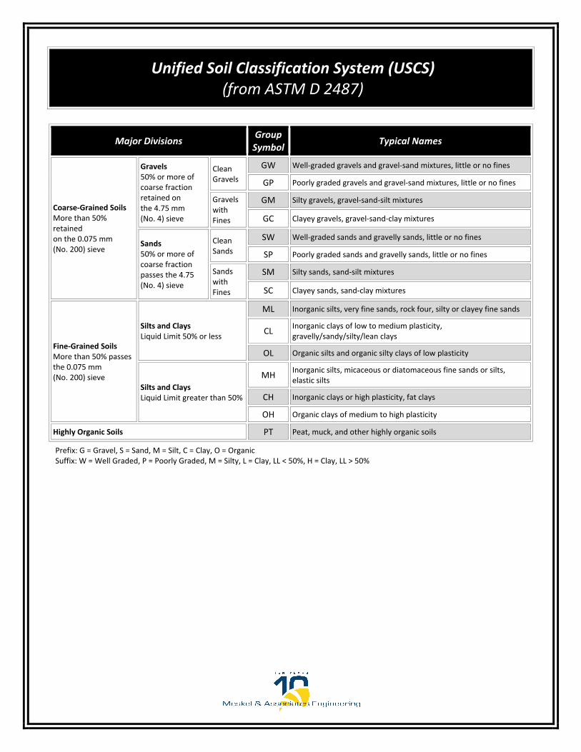
Prefix: G = Gravel, S = Sand, M = Silt, C = Clay, O = Organic Suffix: W = Well Graded, P = Poorly Graded, M = Silty, L = Clay, LL < 50%, H = Clay, LL > 50%
Unified Soil Classification System (USCS) (from ASTM D 2487)
Major Divisions Group Symbol
Typical Names
Coarse‐Grained Soils More than 50% retained on the 0.075 mm (No. 200) sieve
Gravels 50% or more of coarse fraction retained on the 4.75 mm (No. 4) sieve
Clean Gravels
GW Well‐graded gravels and gravel‐sand mixtures, little or no fines
GP Poorly graded gravels and gravel‐sand mixtures, little or no fines
Gravels with Fines
GM Silty gravels, gravel‐sand‐silt mixtures
GC Clayey gravels, gravel‐sand‐clay mixtures
Sands 50% or more of coarse fraction passes the 4.75 (No. 4) sieve
Clean Sands
SW Well‐graded sands and gravelly sands, little or no fines
SP Poorly graded sands and gravelly sands, little or no fines
Sands with Fines
SM Silty sands, sand‐silt mixtures
SC Clayey sands, sand‐clay mixtures
Fine‐Grained Soils More than 50% passes the 0.075 mm (No. 200) sieve
Silts and Clays Liquid Limit 50% or less
ML Inorganic silts, very fine sands, rock four, silty or clayey fine sands
CL Inorganic clays of low to medium plasticity, gravelly/sandy/silty/lean clays
OL Organic silts and organic silty clays of low plasticity
Silts and Clays Liquid Limit greater than 50%
MH Inorganic silts, micaceous or diatomaceous fine sands or silts, elastic silts
CH Inorganic clays or high plasticity, fat clays
OH Organic clays of medium to high plasticity
Highly Organic Soils PT Peat, muck, and other highly organic soils

Appendix B
_____________________________________________________________________________________

B-1 4 7 23 22 SC
B-1 6 14 73 36
B-2 4 7 13 24 SM
7 ---7 56 37 36 1917 CL
CH
Borehole %<#200Sieve
WaterContent
(%)
OrganicContent
(%)
LiquidLimit
PlasticLimit CommentsPlasticity
Index ClassificationUSCS
DATE.
SUMMARY OF LABORATORYTEST RESULTS
Approx.Depth
(ft)Sample No.
PROJECT NAME JEA District 2 New Pump Stations-Robena Road
PROJECT LOCATION Jacksonville, Florida
B-3
CLIENT CDM Smith, Inc.
PROJECT NO. 0011-0017
LAB
SU
MM
AR
Y_M
AE
_ALL
PR
OJE
CT
S -
GIN
T S
TD
US
LA
B.G
DT
- 1
/10/
18 1
5:2
2 -
F:\G
INT
\GIN
T F
ILE
S\P
RO
JEC
TS
\001
1-0
017\
LA
B_R
OB
EN
A R
D-J
EA
DIS
TR
ICT
2 N
EW
PU
MP
ST
AT
ION
S.G
PJ
FL Certificate of Authorization No. 281428936 Western Way, Suite 12Jacksonville, FL 32256P: (904)519-6990 F: (904)519-6992
---
---
---
---
---
---
---
---
---
---
---
---
---
B-2
Meskel & Associates Engineering, PLLC
B-5--- --- ---
---
B-5 3 5 22 19 SC
7 20 CH82 32 53 19 34
B-4 3 5 24 22 SC
B-4 9 9 29 0.7 SP-SM---
---
---
--- ---
---
---
---
B-3 9 29 33 48 SM--- --- ------
7 18 32 29 1734 17 SC
--- --- ------B-3 8 24 40 23 SC
Note: "---" Untested Parameter
6/19/2018
---

B-10 7 14 5 22 SP-SM
B-6 7 19 3 23 SP
B-7 1 1 6 31 SP-SM
B-8 9 29 4 23 SP
B-9 4 7 11 21 SP-SM
Borehole %<#200Sieve
WaterContent
(%)
OrganicContent
(%)
LiquidLimit
PlasticLimit CommentsPlasticity
Index ClassificationUSCS
DATE.
SUMMARY OF LABORATORYTEST RESULTS
4/25/2018
Approx.Depth
(ft)Sample No.
PROJECT NAME JEA District 2 New Pump Stations-Pulaski Road
PROJECT LOCATION Jacksonville, Florida CLIENT CDM Smith, Inc.
PROJECT NO. 0011-0017
LAB
SU
MM
AR
Y_M
AE
_ALL
PR
OJE
CT
S -
GIN
T S
TD
US
LA
B.G
DT
- 4
/25/
18 1
1:4
4 -
F:\G
INT
\GIN
T F
ILE
S\P
RO
JEC
TS
\001
1-0
017\
LA
B_P
ULA
SK
I RD
-JE
A D
IST
RIC
T 2
NE
W P
UM
P S
TA
TIO
NS
.GP
JFL Certificate of Authorization No. 281428936 Western Way, Suite 12Jacksonville, FL 32256P: (904)519-6990 F: (904)519-6992
Note: "---" Untested Parameter
Meskel & Associates Engineering, PLLC
---
---
---
---
---
---
---
---
---
---
---
---
---
---
---
---
---
---
---
2.1

B-11 2 3 29 24 SC
B-11 5 9 26 23 SC
B-11 8 24 49 48 SC
Borehole %<#200Sieve
WaterContent
(%)
OrganicContent
(%)
LiquidLimit
PlasticLimit CommentsPlasticity
Index ClassificationUSCS
DATE.
SUMMARY OF LABORATORYTEST RESULTS
8/24/2017
Approx.Depth
(ft)Sample No.
PROJECT NAME JEA District 2 New Pump Stations-Harts Road Site
PROJECT LOCATION Jacksonville, Florida CLIENT CDM Smith, Inc.
PROJECT NO. 0011-0017
LAB
SU
MM
AR
Y_M
AE
_ALL
PR
OJE
CT
S -
GIN
T S
TD
US
LA
B.G
DT
- 6
/12/
18 1
0:3
2 -
F:\G
INT
\GIN
T F
ILE
S\P
RO
JEC
TS
\001
1-0
017\
LA
B_J
EA
DIS
TR
ICT
2 N
EW
PU
MP
ST
AT
ION
S-H
AR
TS
RD
.GP
JFL Certificate of Authorization No. 281428936 Western Way, Suite 12Jacksonville, FL 32256P: (904)519-6990 F: (904)519-6992
Meskel & Associates Engineering, PLLC
---
---
---
--- ---
---
---
---
--- --- --- ---
Note: "---" Untested Parameter

LABORATORY TEST PROCEDURES
Percent Fines Content
The percent fines or material passing the No. 200 mesh sieve of the sample tested was
determined in general accordance with the latest revision of ASTM D 1140. The percent fines
are the soil particles in the silt and clay size range.
Natural Moisture Content
The water content of the tested sample was determined in general accordance with the latest
revision of ASTM D 2216. The water content is defined as the ratio of “pore” or “free” water in
a given mass of material to the mass of solid material particles.
Atterberg Limits
The Atterberg Limits consist of the Liquid Limit (LL) and the Plastic Limit (PL). The LL and PL
were determined in general accordance with the latest revision of ASTM D 4318. The LL is the
water content of the material denoting the boundary between the liquid and plastic states. The
PL is the water content denoting the boundary between the plastic and semi‐solid states. The
Plasticity Index (PI) is the range of water content over which a soil behaves plastically and is
denoted numerically by the difference between the LL and the PL. The water content of the
sample tested was determined in general accordance with the latest revision of ASTM D 2216.
The water content is defined as the ration of “pore” or “free” water in a given mass of material
to the mass of solid material particles.
Organic Loss on Ignition (Percent Organics)
The organic loss on ignition or percent organic material in the sample tested was determined in
general accordance with ASTM D 2974. The percent organics is the material, expressed as a
percentage, which is burned off in a muffle furnace at 455±10 degrees Celsius.

Appendix C
_____________________________________________________________________________________

Steel Substructure
Concrete Substructure
B-3/2,3,4* 30° 26'56.24" N 81° 42'35.42" W 2 to 8 4.57 6,600 45 51Extremely Aggressive
Extremely Aggressive
B-8/2,3,4* 30° 27'16.85" N 81° 36'45.42" W 2 to 8 5.01 23,100 30 18Extremely Aggressive
Moderately Aggressive
GPS Coordinates Latitude/Longitude
* Composite samples were tested
Summary of Corrosion Series Test Results
Duval County, FloridaMAE Project No.: 0011-0017
Boring/Sample No.Approximate
Test Depth (ft)Resistivity (ohm-cm)
Chlorides (ppm)
Sulfates (ppm)
Environmental ClassificationpH
JEA District 2 Pump Station and Flow Rerouting - Robena Road and Pulaski Road
Page 1 of 1