finite element simulations of internal stresses generated
TRANSCRIPT
HAL Id: jpa-00254155https://hal.archives-ouvertes.fr/jpa-00254155
Submitted on 1 Jan 1996
HAL is a multi-disciplinary open accessarchive for the deposit and dissemination of sci-entific research documents, whether they are pub-lished or not. The documents may come fromteaching and research institutions in France orabroad, or from public or private research centers.
L’archive ouverte pluridisciplinaire HAL, estdestinée au dépôt et à la diffusion de documentsscientifiques de niveau recherche, publiés ou non,émanant des établissements d’enseignement et derecherche français ou étrangers, des laboratoirespublics ou privés.
Finite Element Simulations of Internal StressesGenerated During the Ferroelastic Deformation of NiTi
BodiesP. Manach, D. Favier, G. Rio
To cite this version:P. Manach, D. Favier, G. Rio. Finite Element Simulations of Internal Stresses Generated During theFerroelastic Deformation of NiTi Bodies. Journal de Physique IV Proceedings, EDP Sciences, 1996,06 (C1), pp.C1-235-C1-244. �10.1051/jp4:1996123�. �jpa-00254155�
JOURNAL DE PHYSIQUE IV Colloque Cl , supplCment au Journal de Physique 111, Volume 6, janvier 1996
Finite Element Simulations of Internal Stresses Generated During the Ferroelastic Deformation of NiTi Bodies
P.Y. Manach. D. Favier* and G. Rio
Laboratoire de Ge'nie Mdcanique et Mate'riaux, Centre de Ge'nie Industriel, Guidel Plages, Universite' de Bretagne Sud, 56520 Guidel, France * Laboratoire des Sols, Solides et Structures, Unite' de Recherche Associde au CNRS n.01511, Universitd Joseph Fourier, BP. 53X, 38041 Grenoble
Abstract. The aim of this paper is to analyse the generation of internal stresses during the predeforma-
tion of NiTi shape memory alloys in the martensitic state. This allows to determine the initial stress state
in which the material will transform during the shape memory effect due to heating coilsecutively to this
prestrain. In that way a three-dimensional finite element model of the deformation of shape memory alloys
has been developed, the constitutive law being defined using an elastohysteresis tensor model. The influence
of behavioural and geometrical factors are illustrated considering the numerical simulation of different cases
of practical importance for industrial applications : the study of the bending behaviour of a NiTi cantilever
beam as well as the study of the swelling of a pipe connection under both uniform and non uniform internal
displacement fields.
1 INTRODUCTION
Designing with shape memory alloys (SMA) is far more complicated than with non transforming materials. Free recovery is very often presented as the simplest of the shape memory events consisting of a deformation of the martensite and then heating to recover the original shape. However in most of the complex structure bodies, this shape memory effect has to be performed under stress, due to the fact that internal stresses are generated during the predeformation of the alloy in the martensitic state. In order to better determine the initial stress state from which the material will transform consecutively to the prestrain, it is necessary to study the influence of this prestrain on the generation of internal stresses in shape memory parts.
In order to feature accurately the generation of internal stresses during prestrain, the influence of both behavioural and geometrical aspects has to be analyzed. Below M s the deformation occurs mainly by twinning and/or martensitic reorientation and specific constitutive laws have to be used to model the resulting non usual mechanical behaviour, including non elastic springback strain during unloading. In that way, a three-dimensional finite element model of the deformation of shape memory alloys has been developed in order to analyze and predict the mechanical behaviour of NiTi parts. According to the strong non-linearity of the mechanical behaviour, the formulation of the model is developed in the case of large geometrical transformations including large deformations. In this context, a general three-dimensional kinematic has been studied. The constitutive behaviour is defined using an elastohysteresis tensor model which is based on the splitting of the Cauchy stress tensor into two fundamental stress contributions of hyperelastic and pure hysteresis types respectively. Such a constitutive law has already shown its applicability for SMA [l] [2] [3]. The equilibrium equations are then deduced using the principle of virtual power, the system of non-linear algebraic equations being solved by the Newton-Raphson method.
Article published online by EDP Sciences and available at http://dx.doi.org/10.1051/jp4:1996123
Cl-236 JOURNAL DE PHYSIQUE IV
This paper is devoted to the presentation of the 3~ finite element modelling of the deformation of SMA in martensitic state. In the first part, the finite element formulation concerning the three- dimensional kinematic, the elastohysteresis constitutive law as well as the variational formulation is briefly recalled for it has already been presented in [4]. In the second part, the influence of all the behavioural factors together with the geometrical factors are illustrated considering the finite element simulation of two different cases of practical importance : firstly the bending behaviour of a NiTi cantilever beam and secondly the swelling of a NiTi pipe connection under both uniform and non-uniform internal displacement fields. These numerical simulations are performed using material parameters which have been identified on experimental shear tests results [3].
2 FINITE ELEMENT FORMULATION
The finite element formulation of the model is written using a general three-dimensional kinematic, no particular direction being favoured ; such a formulation allows to study any type of NiTi bodies. The definition of this kinematic in terms of mechanical and numerical involvement in the finite element program is briefly reviewed in this section.
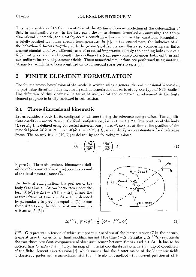
2.1 Three-dimensional kinematic Let us consider a body R, its configuration at time t being the reference configuration. The equilib- rium conditions are written on the final configuration, i.e. at time t + At. The position of the body R, see Fig.1, is defined using convected material coordinates Q', so :hat at time t, the position of the material point M is written as : &?(Q\ t ) = za(8",t) L, where the I, vectors denote a fixed reference frame. The natural frame ( M , 6,) is defined by the following relation :
Figure 1: Three-dimensional kinematic : defi- nition of the convected matefial coordinates and of the local natural frame Gi.
In the final configuration, the position of the body R at time t + At can be written_under the form &?(Qi, t + At) = za(Qi, t +.At) I, and t,he natural frame at time t + At is then denoted by g',, similarly to previous equation (1). From these definitions, the Almansi strain tensor is written as 151 161 :
t+At , .. G represents a tensor of which components are those of the metric tensor G in the natural frame at time t , convected without modification until the time t + At. Similarly, ~ : + * ~ e ; j represents the two times covariant components of the strain tensor between times t and t + At. It has to be noticed that for sake of simplicity, the map of material coordinate is taken as the map of coordinate of the finite element discretization [7], which means that the discretization of the kinematic fields is classically performed in accordance with the finite element method ; the current position of M is
4 -4 -4
then defined by the relation : M = za I, = zaT p, I,, where the interpolation functions cp, depend on a coordinate map J" on the reference element, i.e. cp, = y,([". The choice [h 0' implies that the material coordinates are not continuous between elements. As the elements are assumed isoparametric p, = +, (G, represents the interpolation of the unknown functions), the unknown displacement field Au' between times t and t + At is written as :
2.2 Constitutive behaviour
For SMA, the simultaneous existence of reversible processes and hysteresis [8] suggests to express the Cauchy stress tensor U as the addition of two partial stresses, the first one being hyperelastic U,
[l], while the second one is related to hysteresis of elastoplastic type u h [g] [l01 [ll]. This approach leads to study two tensorial schemes of isothermal hyperelasticity and hysteresis respectively. It should. be noted that the pure elastohysteresis scheme allows the description of classical effects (i.e. superelasticity and ferroelasticity) as well as shape memory effect [l].
2.2.1 Hyperelastic behaviour
Let E be the density of elastic energy. If we denote by g = det I g,, 1, the hyperelastic stress contribution U, can be defined by the rate form :
D denotes the strain rate tensor for which 2Dij = dgij/dt and in the isothermal case, E is simply the Helmholtz free energy. In the case of SMA, it has to be noticed that the thermomechanical properties are related to the existence of a thermoelastic martensitic transformation which occurs mainly by shear-like mechanisms. From a macroscopic standpoint, if E denotes the Almansi strain tensor between the neutral and current states and if the material is assumed isotropic the choice of the intensity of the deviatoric strain 115 as a first variable of E is thus physically meaningful [1][2]. The set of variables is completed by the ratio of elementary volumes v and by the phase of the deviatoric strain tensor cp?. If we denote by G = det I Gij 1, the ratio of elementary volumes is defined by the relation v = (g/G)lI2. By identifying each terms of relation (4), it can be obtained :
where the cri coefficients are functions of v, fl?, (PS, dE/az~ , d E / a n E and dE/dp,. In the case of shape memory alloys, the form of E has been proposed to be taken as the following relation [l] [2], k,, Q,, p, and p , being parameters depending both on the alloy and on the temperature :
k, ln2v Q2 E = - + 2 1 x 1 cosh - 6 2pT [ (2; a ) ] + 2 p m n E
In the finite element code when material exhibits non-linear physical behaviour, the constitutive relations are used in their incremental form ; they are discretized in space with respect to time-like parameter. This procedure enables obtaining of so called tangent matrix elements necessary when Newton-Raphson implicit procedure is used to solve final equations set. The incremental form of relation (5) as well as its variation with respect to the degrees of freedom has been given in [4].
JOURNAL DE PHYSIQUE IV
2.2.2 Pure hysteresis bel~aviour
From the outset, rheological models containing elastic and slip elements have been considered to derive a general pure hysteresis model [g]. The ma.teria1 is assumed isotropic and the hysteresis contribution (denoted by S ) is only deviatoric. The plastic evolution is limited by the Von Mises criterion which is directly included in the rate-form formulation of the deviatoric Cauchy stress tensor S . Such hypotheses lead to the following constitutive relation :
D denotes the deviatoric strain rate tensor and the deviatoric hysteresis stress tensor S is related to S' through 2s" = SS'; g k ~ + S'; g k 8 . The term 4 = AfS' : D represents the intrinsic dissipation rate [g] and /l4 = -ph/w2S; is such as the Von Mises equivalent hysteresis stress is always lower than
= &So For sake of simplicity, the subscript r represents a reference situation which means that A: describes any evolution between time t and the reference state r . The parameter W denotes the Masing similarity function ; along the first loading path, W is equal to 1 and the reference state is the initial state. For other paths, they are equal to 2 and to the last inversion state respectively as long as any crossing point is not detected. The material parameters are then simply the Lamk's coefficient ,uh and the yield hysteresis limit So which are easily determined from tensile or simple shear tests [12]. From a numeric standpoint, the constitutive equation is linearized and directly integrated by an implicit Newton method ; such a method requires a calculation of all different values at time t + At. The derivative of S' with respect to time leads to the following quadratic expression of the constitutive equation :
with : ~:+Ats f i - ~;+A"fi - ~;sl;
k - (9)
If we denote by : [ F ' ~ i ] = [ p4 nik A:+At S': + (h 4 - 1) hik hij ] (10)
where 6 represents the Kronecker symbol, the variation of the deviatoric stress tensor with respect to the degrees of freedom which is needed in the tangent linear form is obtained through :
The management of inversion and crossing points is performed using the intrinsic dissipation rate function 4 defined previously. This value is related to a volumeelement and must always be positive ; thus, the stat.e at time t is an inversion point when the function 4 becomes negative. Furthermore the management of crossing points is performed by using an associate function W defined by the relation [g] [l11 :
After each inversion point, the level reached by the W function is memorized and W is set to zero for the next evolution. This function represents in fact a measurement of the energy exchanged along the path between two inversion points. A crossing point is then observed when the current level of exchanged energy reaches a previous memorized level of W, reached on a previous branch. The crossing point represents the closure of a cycle which can then be erased.
2.3 Variational formulation
The weak formulation of the boundary-value problem defined by the boundary conditions and by the equilibrium equations, which are both written on the final configuration, is obtained by using the principle of virtual power. Let R be the region occupied by the material and C its boundary ; from the finite element discretization and taking into account an arbitrary virtual velocity field in R and fulfilling displacement boundary conditions on C, this leads with (3) to the system of algebraic non-linear equations :
* bs V corresponds to the virtual velocity of a degree of freedom ( b coordinate of the node S ) , v' being chosen under the same form as the displacement field. Ail denotes the displacement between time t and t + At, ;the vector of surfacic external forces and Rb, the residuum. The previous system is finally solved using the Newton-Raphson method.
3 RESULTS A N D DISCUSSION
This section is devoted to the numerical study of the ferroelastic three points bending behaviour of a NiTi cantilever beam as well as the swelling of a NiTi pipe connection under both a uniform and non-uniform internal displacement field. The aim is to analyze the generation of internal stresses during the ferroelastic deformation prior to the shape memory effect and to feature the residual stress distributions at the end of the prestrain process. The material parameters have been identified on an industrial NiTi alloy from the experimental results obtained in tension and in simple shear by Manach [3] [12]. In martensitic state, Q, is set to zero for it characterizes the stress-induced martensitic transformation in the austenitic state and the other parameters are k, = 95000 MPa, p, = 22500 MPa, pm = 1000 MPa, ph = 15000 MPa and Soh = 200 MPa. Thus, the numerical stress-strain curve obtained using these parameters features the rubber-like behaviour which is characteristic of the nlartensitic state behaviour, see also [4].
3.1 Shape memory alloy cantilever beam
The use of SMA in industrial applications necessitates to describe their behaviour, not only as tensile test specimen in which the stress is homogeneous but also as mechanical elements such as beams where the stress distribution is non-homogeneous. For example, in the case of cantilever beams which are used for several industrial applications [13], the SMA element is stressed in bending with a non-uniform stress distribution over the cross section, which produces a maximum tension and com- pression stress occuring at the outer fibers of the beam. Moreover, for such materials, the deflection of the beam is not a linear function of the force, so that mechanical engineering classical formulaes cannot be used. Furthermore, it is important to determine the residual stress state consecutive to a prestrain in the martensitic state before the shape memory effect. Thus, it is obvious that these problems lead the usual method of calculation to be inefficient. Different studies based on strength of materials' approach have already been published to model the deformation of simple beam in bending [l41 [l51 ; among them, the one proposed by Orgeas et al. [l61 is developed using one-dimensional elastohysteresis scheme and small deformation theory but takes into account large displacement and non-symmetric tension-compression behaviour.
The finite element approach presented in this paper, is developed for any 3 D body including large geometrical transformations and is obviously more general than the previous ones ; this allows to get information on quantities which are neglected in the above studies, as for example the shear
Cl-240 JOURNAL DE PHYSIQUE IV
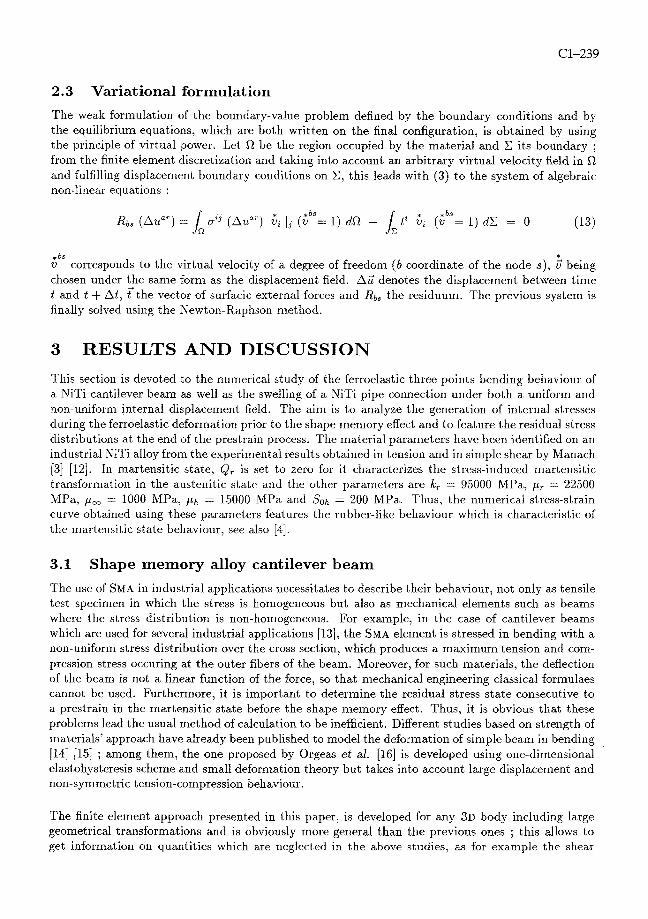
stress arising during bending. The beam which has been studied has the following dimensions : 80 X 8.5 x 2.6 mm. For symmetry reasons, only the quarter of the beam, presented in Fig.2.a, has been used for this test.
U DEFLECTION (mm)
Figure 2: (a) Mesh of the cantilever beam used for the numerical simulation : 1. initial mesh and 2. maxinlu~n deflection mesh. (b) Force-deflection loading and unloading curve obtained at point C.
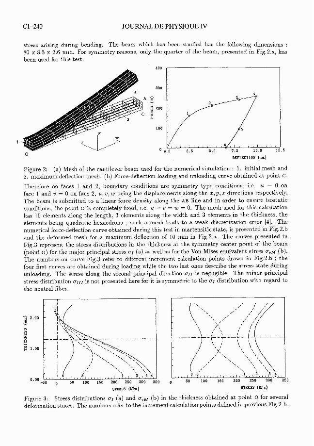
Therefore on faces 1 and 2, boundary conditions are symmetry type conditions, i.e. U = 0 on face l and 71 = 0 on face 2, U , v, W being the displacements along the X, y, z directions respectively. The beam is submitted to a linear force density along the AB line and in order to ensure isostatic conditions. the point 0 is completely fixed, i.e. u = v = W = 0. The mesh used for this calculation has 10 elements along the length, 3 elements along the width and 3 elements in the thickness, the elements being quadratic hexaedrons ; such a mesh leads to a weak discretization error [4]. The numerical force-deflection curve obtained during this test in martensitic state, is presented in Fig.2.b and the deformed mesh for a maximum deflection of 10 mm in Fig.2.a. The curves presented in Fig.3 represent the stress distributions in the thickness at the symmetry center point of the beam (point 0 ) for the major principal stress a1 (a) as well as for the Von Mises equivalent stress u , ~ (b). The numbers on curve Fig.3 refer to different increment calculation points drawn in Fig.2.b ; the four first curves are obtained during loading while the two last ones describe the stress state during unloading. The stress along the second principal direction is negligible. The minor principal stress distribution is not presented here for it is symmetric to the distribution with regard to the neutral fiber.
STRESS (MPa) STRESS (MPa)
Figure 3: Stress distributions a1 (a) and u , ~ (b) in the thickness obtained at point 0 for several deformation states. The numbers refer to the increment calculation points defined in previous Fig.2.b.
First of all, as the force-deflection curve features the typical ferroelastic behaviour of the martensitic state, the residual deformation after unloading is rather important, somewhat similar to what ob- tained for classical metallic materials. This residual deflection depends on the material parameters, i.e. of the temperature at which this deformation takes place. On one hand, the value of the principal stress 01 represents for the bottom outside fiber, the tensile longitudinal stress due to the bending sollicitation. Conversely, the value of 0111 would represent for the top outside fiber, the compression stress. During loading, the value of a1 starts from a quasi-linear curve for the first increment calcula- tion point while for higher strain levels the a1 stress distribution is characterized by a rounded curve which is a classical shape for elastoplastic constitutive behaviour. On the other hand, the Von Mises equivalent stress distribution includes shear stress components which are maximum on the neutral fiber and vanish on the outer fibers. In that way, the Von Mises stress distribution is symmetric with respect to the neutral fiber, its value being equal to the axial stress on the outer fibers and reflecting the shear stress on the neutral fiber.
Using strength of materials' approach [l61 and according to Kirchhoff assumption, the application of a bending momentum to a prismatic beam involves a rigid body rotation of a cross section normal to the longitudinal axis X, characterized by its curvature radius R. This leads to a longitudinal displacement field expressed as : U, = xz/R. Expressing the deformation (assumed as small) as : c,, = dt~,/dx = z/R, the longitudinal stress field a,, in a cross section can then be determined using the constitutive law. Due to the inelastic behaviour of SMA, the stress is not linearly related to the z coordinate and the expression of the bending momentum is rather complicated. However, as the E,, distribution is a linear function of z with a slope equal to 1/R, and as in the strength of materials' approach the shear stress is neglected, the a,, stress distribution along the thickness has a similar shape than that of the tensile stress-strain curve at the beginning of the first loading. When the deflection of the beam increases, the a,, distribution departs from a quasi-linear curve. This tendancy can be observed on the curves 1, 2, 3, 4 of Fig.3.a for the major principal stress. The observation of Fig.3.b shows that the shear stress can not be neglected as it has been done in all the strength of materials' approach [l41 [l51 [16]. The most interesting part of this calculation lies in the stress distributions during unloading for it allows to determine the springback effect as well as the residual stress state in the beam. It can be observed in Fig.2.a that during a progressive unloading, an elastic springback of each fiber is produced. The a1 principal stress decreases to reach the value presented on curve 6. At the end of the unloading, the internal fibers remain constrained. For fibers below the neutral fiber, the value of the principal stress 01 follows a S-shape curve which is due to the somewhat elastoplastic character of the constitutive law. Similarly, the Von.Mises equivalent stress distribution is reversed during unloading and the outer fibers of the beam as well as the neutral fiber remain under stress even when the force is released.
3.2 Shape memory alloy pipe connector
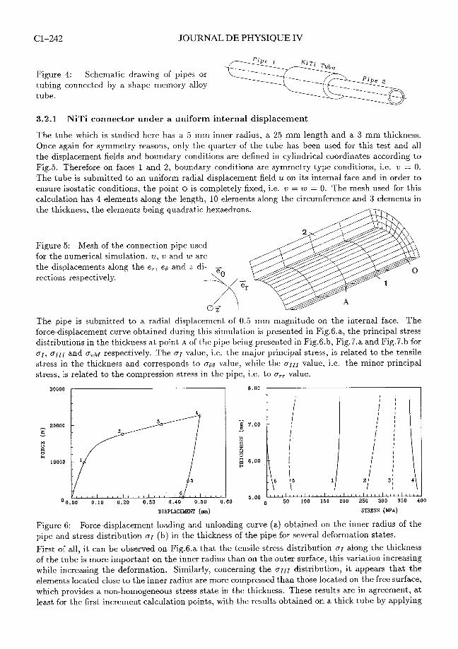
Another well established use for shape memory alloys is that of connectors for tubing and, similarly, pin and socket type connectors [17]. The procedure in these applications is to manufacture a tube of shape memory alloy which has a somewhat smaller inner diameter in the austenitic state than the outer diameter of the pipes to be connected. At a temperature less than As the SMA tube is then deformed into partially reoriented martensite such that the inner diameter exceeds slightly that of the tubing. The SMA tube is placed over the pipes in this phase and then heated. As the reverse transformation occurs, the material attempts to recover the initial residual strain, the seal being then immediately effected. In this section, two analyzes are undertaken to simulate such an application (see Fig.4) and to demonstrate the potential of the finite element calculation. The first case concerns the study of a NiTi pipe connection submitted to an uniform internal displacement while the second consists of the calculation of a real industrial connector including slots. In this last case, the tube is submitted to a radial displacement field at both slots.
JOURNAL DE PHYSIQUE IV
Figure 4: Schematic drawing of pipes or tubing connected by a shape memory alloy tube.
3.2.1 NiTi connector under a uniform internal displacement
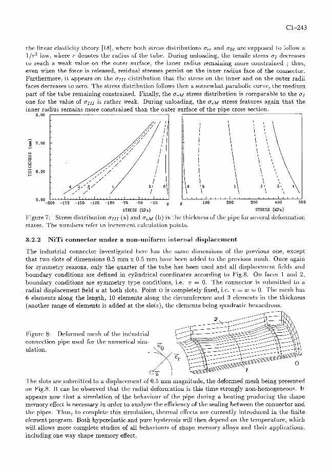
The tube which is studied here has a 5 mm inner radius, a 25 mm length and a 3 mm thickness. Once again for symmetry reasons, only the quarter of the tube has been used for this test and all the displacement fields and boundary conditions are defined in cylindrical coordinates according to Fig.5. Therefore on faces 1 and 2, boundary conditions are symmetry type conditions, i.e. v = 0. The tube is submitted to an uniform radial displacement field U on its internal face and in order to ensure isostatic conditions, the point o is completely fixed, i.e. v = W = 0. The mesh used for this calculation has 4 elements along the length, 10 elements along the circumference and 3 elements in the thickness, the elements being quadratic hexaedrons.
Figure 5: Mesh of the connection pipe used for the numerical simulation. U, o and W are the displacements along the e,, eo and z di- - rections respectively.
.-_-̂ ji The pipe is submitted to a radial displacement of 0.5 Inn1 magnitude on the internal face. The force-displa.cement curve obtained during this simulation is presented in Fig.G.a, the principal stress distributions in the thickness at point A of the pipe being presented in Fig.G.h, Fig.7.a and Fig.7.b for ar, a I I I and a , ~ respectively. The value, i.e. the major principal stress, is related to the tensile stress in the thickness and corresponds to see value, while the 0111 value, i.e. the minor principal stress, is related to the compression stress in the pipe, i.e. to a,, value.
DISPLACEMENT (m) STRESS (MPa)
Figure G: Force-displacement loading and unloading curve (a) obtained on the inner radius of the pipe and stress distribution 01 (b) in the thickness of the pipe for several deformation states.
First of all, it can be observed on Fig.6.a that the tensile stress distribution a1 along the thickness of the tube is more important on the inner radius than on the outer surface, this variation increasing while increasing the deformation. Similarly, concerning the distribution, it appears that the elements located close to the inner radius are more compressed than those located on the free surface, which provides a non-homogeneous stress state in the thickness. These results are in agreement, at least for the first increment calculation points, with the results obtained on a thick tube by applying
3.2.2 NiTi connector under a non-uniform internal displacement
the linear elasticity theory [18], where both stress distributions U,, and U00 are supposed to follow a 1/r2 law, where r denotes the radius of the tube. During unloading, the tensile stress U I decreases to reach a weak value on the outer surface, the inner radius remaining more constrained ; thus, even when the force is released, residual stresses persist on the inner radius face of the connector. Furthermore, it appears on the 0 1 1 1 distribution that the stress on the inner and on the outer radii faces decreases to zero. The stress distribution follows then a somewhat parabolic curve, the medium part of the tube remaining constrained. Finally, the a , ~ stress distribution is comparable to the or one for the value of 0111 is rather weak. During unloading, the a , M stress features again that the inner radius remains more constrained than the outer surface of the pipe cross section.
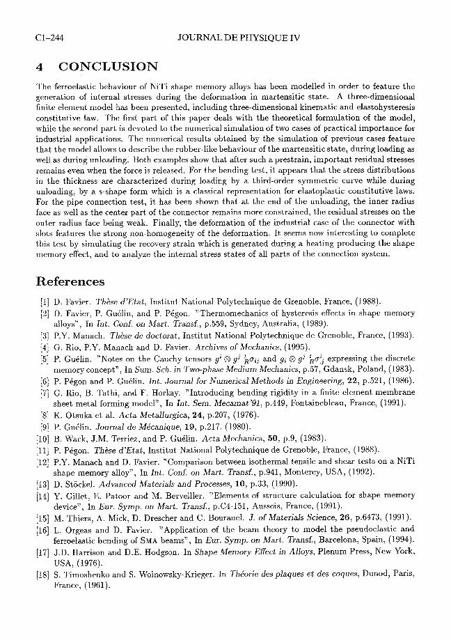
The industrial connector investigated here has the same dimensions of the previous one, except that two slots of dimensions 0.5 mm x 0.5 mm have been added to the previous mesh. Once again for symmetry reasons, only the quarter of the tube has been used and all displacement fields and boundary conditions are defined in cylindrical coordinates according to Fig.8. On faces 1 and 2, boundary conditions are symmetry type conditions, i.e. v = 0. The connector is submitted to a radial displacement field u at both slots. Point o is completely fixed, i.e. v = W = 0. The mesh has 6 elements along the length, 10 elements along the circumference and 3 elements in the thickness (another range of elements is added at the slots), the elements being quadratic hexaedrons.
8.00
3 7.00
U V1 m I g 6.00 b
5.00
Figure 8: Deformed mesh of the industrial connection pipe used for the numerical sim ulation.
-
- \ \\,,\ 1 , 1 1 l l , \ \ - \
! 1 ,
51 6 1 \ '\ 21 3 \ 4
\ \,
" " " " ' " " ' " ' " " " ' " " ' 1 " " 1 " " I , , , , I I I I , I * I I I l I 9 I I
The slots are submitted to a displacement of 0.5 mm magnitude, the deformed mesh being presented on Fig.8. It can be observed that the radial deformation is this time strongly non-homogeneous. It appears now that a simulation of the behaviour of the pipe during a heating producing the shape memory effect is necessary in order to analyze the efficiency of the sealing between the connector and the pipes. Thus, to complete this simulation, thermal effects are currently introduced in the finite element program. Both hyperelastic and pure hysteresis will then depend on the temperature, which will allows more complete studies of all behaviours of shape memory alloys and their applications, including one way shape memory effect.
-200 -175 -150 -125 -100 -75 -50 -25 0 0 100 200 300 400 500
STRESS (Wa) STRESS (Wa)
Figure 7: Stress distribution 0111 (a) and 0 , ~ (1)) in the thickness of the pipe for several deformation states. The nunlbers refer to increnlent calculation points.
Cl-244 JOURNAL DE PHYSIQUE IV
4 CONCLUSION
The ferroelastic behaviour of NiTi shape memory alloys has been modelled in order to feature the generation of internal stresses during the deformation in martensitic state. A three-dimensional finite element model has been presented, including three-dimensional kinematic and elastohysteresis constitutive law. The first part of this paper deals with the theoretical formulation of the model, while the second part is devoted to the numerical simulation of two cases of practical importance for industrial applications. The numerical results obtained by the simulation of previous cases feature that the model allows to describe the rubber-like behaviour of the martensitic state, during loading as well as during unloading. Both examples show that after such a prestrain, important residual stresses remains even when the force is released. For the bending test, it appears that the stress distributions in the thickness are characterized during loading by a third-order symmetric curve while during unloading, by a S-shape form which is a classical representation for elastoplastic constitutive laws. For the pipe connection test, it has been shown that at the end of the unloading, the inner radius face as well as the center part of the connector remains more constrained, the residual stresses on the outer radius face being weak. Finally, the deformation of the industrial case of the connector with slots features the strong non-homogeneity of the deformation. It seems now interesting to complete this test by simulating the recovery strain which is generated during a heating producing the shape memory effect, and to analyze the internal stress states of all parts of the connection system.
References
[l] D. Favier. Thi.se d7Etat, Institut National Polytechnique de Grenoble, France, (1988). ['2] D. Favier, P. Guklin, and P. Pigon. "Thermomechanics of hysteresis effects in shape memory
alloys", In Int. Conf. on Mart. Transf., p.559, Sydney, Australia, (1989). [3] P.Y. Manach. Thgse de doctorat, Institut National Polytechnique de Grenoble, France, (1993). [4] G. Rio, P.Y. Manach and D. Favier. Archives of Mechanics, (1995). [5] P. Guilin. "Notes on the Cauchy tensors g' @ g3 ;ceJ and g, @ g3 La; expressing the discrete
memory concept", In Sum. Sch. in Two-phase Medium Mechanics, p.57, Gdansk, Poland, (1983). [G] P. PCgon and P. Guilin. Int. Journal for Numerical Methods in Engineering, 22, p.521, (1986). ['i] G. Rio, B. Tathi, and F. Horkay. "Introducing bending rigidity in a finite element membrane
sheet metal forming model", In Int. Sem. Mecamat'91, p.449, Fontainebleau, France, (1991). [S] K. Otsuka et al. Acta Metallurgica, 24, p.207, (1976). [g] P. Guilin. Journal de Me'canique, 19, p.217, (1980).
[l01 B. Wack, J.M. Terriez, and P. GuClin. Acta Mechanics, 50, p.9, (1983). [l11 P. Pigon. Thhse d'Etat, Institut National Polytechnique de Grenoble, France, (1988). [l21 P.Y. Manach and D. Favier. "Comparison between isothermal tensile and shear tests on a NiTi
shape memory alloy", In Int. Conf. on Mart. Transf., p.941, Monterey, USA, (1992). [l31 D. Stockel. Advanced Materials and Processes, 10, p.33, (1990). [l41 Y. Gillet, E. Patoor and M. Berveiller. "Elements of structure calculation for shape memory
device", In Eur. Symp. on Mart. Transf., p.C4-151, Aussois, France, (1991). [l51 M. Thiers, A. Mick, D. Drescher and C. Bourauel. J . of Materials Science, 26, p.6473, (1991). [l61 L. Orgeas and D. Favier. "Application of the beam theory to model the pseudoelastic and
ferroelastic bending of SMA beams", In Eur. Symp. on Mart. Transf., Barcelona, Spain, (1994). [l71 J.D. Harrison and D.E. Hodgson. In Shape Memory Effect in Alloys, Plenum Press, New York,
USA, (1976). [l81 S. Timoshenko and S. Woinowsky-Krieger. In ThCorie des plaques et des coques, Dunod, Paris,
France, (1961).