fishery bulletin of the fish and wildlife service v.63
TRANSCRIPT

DEVELOPMENT OF A MATHEMATICAL RELATIONSHIP BETWEEN ELECTRIC-FIELD PARAMETERS AND THE ELECTRICAL CHARACTERISTICSOF FISH
By GERALD E. MONAN, Fishery Biologist, and DEREK E. ENGSTROM, Physicist
ABSTRACf
A few of the electrical characteristics of fish were" defined and studied as the criteria for producina a specific, observed reaction. Voltaaes and currents appliedto a small test cell containina a live fish were measured.With the use of an electrical analogue of the cell contents, these data were reduced to the equivalent parameters applied to a mathematical model representing thefish. The resulting values of re~stivity and power
The use of electric fields is presently beinginvestigated as a possible method of divertingfish for safe passage around hydroelectric dams,thus aiding in the perservation of the salmonfisheries. 1
A major problem of this investigatIon is theevaluation of an electric fi~ld as a motivatingstimulus. Prior to the research reported uponhere, few, if any, methods have been developedto oDserve or determine accurately those portionsof a field pattern which motivate the behaviorof a fish. Therefore, the optimum electricalparameters of a particular, effective guidinginstallation may not apply at some other site.In other words, so little is known about how anelectrical field stimulates a fish that it is difficultto design a successfUl electrical-guiding device.Extensive and costly experimentation has beennecessary at each new" installation to obtainthe necessary parameters for an e.ffectiveel~ctrical-guiding device.
NOTE.-Approwd for publication April 17, 1962.I Mason, James E., and Rea Duncan. Manuscript In preparation. The
dEovelopmEont and appraisal of methods of diverting fingerling sahnon withelectricity at Lake Tapps. Bureau of Commercial Fisheries BiologicalLaboratory, Seattle, Wash.
FISHERY BULLETIN: VOLUME 63, NO. 1
density computed for this model were then used todescribe the corresponding fish characteristics. Application of pulsed voltaaes to the cell demonstrated aminimum power density below which no reaction wasobserved. Equations were then derived to relate thisvalue to correspondina electrical conditions that wouldexist at an electrical gUiding installation.
An. investigation of this problem indicates thatan adequate solution would include a mathematical method of relating electric-field parameters tothe electrical characteristics of the fish. "Thesecharacteristics control the response of the fishto electricity and thus define for the fish specificregions in an electrical field. However, becauseof .the complexity of the biological structureinvolved, a precise description of these characteristics is impossible. The mathematical processtherefore, "must utilize an electrical analogue tofacilitate such a description. .
The research presented here has three objectives: (1) To develop a nlathematical model toserve as the electrical analogue of a fish; (3) tofind an evaluation procedure which will determinethe elect,rical properties and processes within themodel, and (3) to develop a method to relate"these model characteristics to the parame"tersof the electric fields to be used in proposedfish-g!liding devices.
MATERIALS AND METHODSThe experiments were conduct,tid at the Bureau
of Commercial Fisheries Biological Laboratory;
123

FIGURE I.-Plastic cells used to contain fish while testing.
Seattle, Wash., from November 27, 1958, toJanuary 9, 1959. The fish used were 0 age-groupsockeye salmon (Oncorhynchus nerka). These fishwere obtained from the Winthrop National FishHatchery in September, 1958, and were kept inthe laboratory holding facilities until their transferto the experimental area.
The general method of laboratory investigationinvolved measuring voltages and currents appliedto a small, plastic test cell (fig. 1) containing alive fish. Measurements were carried out withthe fish facing either the positive or the negativeelectrode. These parameters were measured coincident with a specific observable reaction of thefish. Measurements of applied voltage were madefrom electrodes positioned within, and at oppositeends of, the cell. These electrodes were designedso the electrical resistance between them would becompletely controlled by the contents of the cell.It was also necessary to reduce the volume of thesurrounding body of water to a minimum in orderto obtain measurements which were analogous tofunctions of the electrical characteristics of a fish.Reactions produced in the fish were created byapplying the necessary voltage across the cell.
The cell voltages used in the calculations were thelowest applied values to which the £ish appeared torespond. This response was selected because itcould oe easily observed and because the stimulusthreshold was well defined. When the applied
124
voltage reached the threshold value, a violentswimming motion was observed. This reactioncould be considered equivalent to the muscleresponse caused by the rheobase potential (Mitchell, 1948), and would correspond to the thresholdreaction reported in later publications (Fisher,1950; Cattley, 1955). Since this observed threshold phenomenon is a property of the biologicalstructure of the fish, any corresponding electricfield gradient should produce the same effect.Therefore, this response defined a characteristicof the fish th!J,t could be related to field-patternparameters.
HOLDING FACILITIES
Holding facilities were set up adjacent to theexperimental area in order to provide ease ofoperation and to minimize any change in waterconditions between the holding troughs and thecell. Fish were held here at least 4 hours priorto testing. "
Equipment for this installation included threewooden troughs, 22 em. wide by 24 cm. deep by196 em. long, and a 1042-liter wooden tank.Dechlorinated city water was supplied to the tankthrough a float valve. From the tank, water was "pumped to a head trough which in turn suppliedthe three holding troughs. Approximately 70perce"nt of the flow from the holding troughs wasdiverted back into the main tank, and 30 percentwas draWn off as waste. A thermostatically controlled refrigeration unit kept the water temperature at approximately 50° F.
APPARATUS
The major portion of the experimental apparatuswas made up of the plastic tank and test cells andthe electronic measuring and testing equipment."The pIexigIass tank had inside dimensions of 25 cm.by 25 em. by 38 cm. and had one fixed partition andone adjustable partition. A test cell (fig. 2) wasplaced between these partitions, and the adjustable partition was positioned and clamped in sucha manner as to hold the cell tightly between thetwo partitions. Electrodes made of duraluminwere placed at both ends of the tank to permit theapplication of the test currents.
Two cells of different size were used in order toaccommodate the range of fish sizes tested. Cellnumber one had inside dimensions of 2.54 cm.wide. 3.81 em. deep, and 15.88 cm. long; whereas
FISH AND WILDLIFE SERVICE

,0
R.
FIGURE 4.-Circuit diagram of the testing, unit: (above)'operate configuration; (below) calibrate configuration:
+
R,
. .FIGURE a.-Circuit diagram of the complete testing unit.
. The electronic circuitry enabled a square wavepulse of the desired amplitude and duration to beapplied to the cell (fig. 3). Electronic switchingequipment, controlled by the investigator (described in detail by Volz (1962» connected theoutput of a d.c. (direct current) generator to thetest circuit at preset intervals and for preset durations. The voltage applied to the circuit wasessentially a square wave pulse with an amplitudeof 120 volts and a duration of 50 milliseconds.
The circuit functions as follows: When switch8\ is in the, operate position; the functioning circuit is the' operate circuit (fig. 4a). In tli~s case, :resistors Rh R2, and ~3 combine to form an' 'adjust-
FELL IHpRt '0
gpgen: ~j"O
G8,1MlIi }J 8.
F,GURE 2.-A test cell in position within the experimental. tank.
cell nwnber two was 1.59 em. wide, 2.54 em. deep,and 11.43 cm. long. Each cell was equippedWith nylon restraining threads stretched horizontally across both ends. The quanity of restrainingmaterial was kept at a minimum by using onlysix threads per end for cell number one and threethreads per end for cell number two. Mo'notoringelectrodes were placed in each cell opening tomeasure the voltage drop across the cell. Theleads for these electrodes were routed throughthe cell wall and up the handle to the externalcircuit. '
Three, types of monitoring electrodes were used.The first arrangement consisted of. a ~-inch wide, .stainless steel strip, cemented to the top wall,just inside each cell opening.. The second typewas 'a ~-inch mesh screen which covered the twoends of the cell, and the third type consisted of asingle wire ,stretched horizontally across the c~
openings. Experimentation with all three typesrevealed that the fish were not sensitive to theproximity of a conducting plane. This information was important for consideration in the designof future cells.
Water was obtained from the holding f~cilities
and was gravity fed to the tank from a 14-gallonreservoir. The rate of flow through the test cellwas kept. at approximately 2 gallons per hour.Water resistivity was conu:olled by the introduction of NaCl.
ELECTRIC FIJllLD AS A MOTIVATING STIMULUS FOR FISH 125

able voltage divider that reduces the 120-voltinput pulse to the required voltage applied to thetaJik.· This voltage is applied ~o the tank electrodes and is monitored on the oscilloscope bymeans of the monitoring electrodes. .Resistor Rsis used to change scale readings on the oscilloscopeby one-half, when necessary, in order to achievethe maximum possible accuracy.
When switch 8 1 is placed in the calibrate position,the functioning circuit is the calibrate circuit (fig.4b). In this case battery B and resistor R,supply p.n adjustable d.c. voltage to the tankelectrodes. The voltage drop across the cell isnow measured on the oscilloscope. Switch 82
prevents current from flowing in the monitoringcircuit until the operator is ready to record thereading. This operation is necessary in order toprevent the electrodes from becoming polarizedand giving erroneous readings. After the readings have been taken, depolarization is ac.complished by closing switch 82 and placing switch81 in the "cell shor.t" position. With the switchin this position, the cell electrodes are shorted,thus returning the circuit to equilibrium.
MEASUREMENT PROCEDURE
After preliminary experimentation, a specificmeasurement procedure was adopted. The fishto be tested was taken from the holding trough andwas placed in the plexiglass tank. The test cellwas then lowered over the fish and positioned sothat the openings at the ends of the cell coincidedwith the openings in the partitions. The resistivity of the water entering the test cell was thenmeasured with a st!IDdard resistivity bridge.
After the fish was allowed a two-minute rest,switch 8 1 was placed in the operate position, andthe electronic pulsing device was triggered.Pulses with a duration of 50 milliseconds werethen automatically applied at· intervals of. 20·seconds. Between each pulse application, thepotentiometer (R2) was manually rotated to in- .crease the pulse amplitude. When the reactionlevel was reac,hed, the fish jumped violently, andthe operator, observing this reaction, recorded thepulse voltage from the oscilloscope.
The battery voltage (B1) was used to establishthe relationship between the pulse voltage acrossthe tank and the actual voltage across the cell.The desired level of current was set, and thevoltage waS recorded -from the voitmeter (M1).
126
With switch 82 closed, switch 8 1 was moved to thecell short po~ition and the cell electrodes wereshorted for 30 seconds. .With switch 82 open,switCh 8 1 was turned to the calibrate position.Switch 82 was then closed, and the voltage wasimmediately recorded from the oscilloScope.Three levels ·of current were used for each fishtested; and measurements were repeated at leasttwice at each level to insure accuracy.
After being tested, each fish was lifted from thecell in a net, and after the excess water, clingingto the fish, was eliminated, the fish was placed ina graduated cylinder partially filled with water.The volume of the displaced water was thenrecorded as the volume of the fish.
The complete testing procedure took approximately 15 minutes per fish. After the volumemeasurement was completed, each fish was re.turned to the appropriate trough, where it washeld for several days. No mortalities occurredamong the fish ~ested.
ANALYSIS PROOEDURE
The symbols listed below are used in the c1is-cu~sions that follow: .
p/=fish resistivity.p..=water resistivi~y.
V/=fish volume.Vc=cell volume.L=fish length.D=distance between cell electrodes.R=resistance of the cell containing the fish.
R.=resistance of the cell without the fish.E=d.c. voltage drop across the cell.
E"=d.c. voltage applied to the tank.E'=reaction voltage applied to the tank.V = guiding-field gradient. .
p/.=power density in the fish.P ...= power density in the water.
I=d.c. current through the cell.m=empirical function of p.. and PI'
Appendix A contains a glossary which may beuseful to readers who are not familiar w~th electrical laws' and terms. The following discussionis purposely brief; however, the subject is coveredin more detail in appendix B. The mathematicalmodel of the fish was developed by constructingan electrical analogue of the contents of the testcell. The analogue was developed by dividingthe cell into a number of rectangular parallelepipeds, one of which represented the fish and theremaining ones represented the water ~thin thecell. The size of the parallelepiped representing
FISH AND WILDLIFE SERVICE

the fish was dependent upon the size of the fish,whereas the dimensions of the remaining parallelepipeds were functions of both cell and fishgeometry. '
The correct ·partitioning of the cell's contentsinto parallelepipeds was governed by the followingrequirements: (1) the calculated fish resistivitymust remain constant as the water resistivity isvaried over a specified range, (~) there must be apractical limitation on the comple.....a.ty of theresulting equations,and (3) the accuracy require-·ments of the resulting equations must not exceedthe capabilities of existing measuring techniques.These are the restrictions which were used indevising the mathematical model of the fish.
In the partitioning scheme, each parallelepipedof the celi model was treated as a resistive-circuitcomponent. The end or cross sectional boundaries served as conn~ting terminals, whereas theremaining surfaces were considered nonconducting.The resistance of each of the parallelepipeds wasre~ated to the resistivity or" its enclosed medium byusing Ohm's Law. The result was a set of equations called ·component equations which relatedcell dimensions, fish dimensions, water resistivity.and fish resistivity to the resistance of a corresponding circuit component. Thus, an analoguecircuit of the cell's contents was devised by' replacing each parallelepiped of the cell model withan equivalent two-terminal resistive component.The tot~l resistance of this analogue circuit wasdesignated to be the cell's resistance. An equation was obtained by using the known properties ofresistors to relate this resistance to the resistance~f each component. This equation was called thecircuit equation. By substitution of the component equations for the resistance values in thecircuit equation, a relationship was obtained between the cell resistance and the r~istivityof the.fish model. Thus, the resulting equation provideda method of evaluating a specific property of thefish.
The transformation from the actual cell to thatof the model of the cell's .contents can be moreclearly visualized by mentally subdividing -theactual cell volume into infinitesimal volume elements. These elements would be of equal volumeand can be called differential volume elements(similar to the units used in the differential theory)f calculus).
The transformation consists of transferring each
element of the cell volume into a parallelepiped inthe model of the cell's contents. The correct distribution of volume elements should be. carriedout in s.uch a way that the total power in eachparallelepiped will be equal to the power dissipatedin a corresponding circuit component for all valuesof water resistivity. In order to complete thetransformation, the lines of current flow can berotated in each differential element without changing the power dissipated by. the element. .Thisallows these current lines to be arranged to correspond with those current lines which would be
_ expected to exist in each parallelepiped. Afterconsiderable prelimina.ry experimentation, two.configurations were chosen which best fulfilled thepreviously established criteria.
The first partitioning plan divided the cell'scontents into four parallelepipeds; three represented the total water in the cell. The fourthparallelepiped, which represented the fish, wasdesignated as the fish model. The correspondinganalogue circuit was composed of four resistors(RlI the fish; and R2, Ra, and R4, the water) connected in a series-parallel network. This .¥1"angemoot was satisfactory in .all ranges of waterresistivities tested except ~hen the resistivityof the fish was greater than the resistivity of thesurrounding water. It was. in this region thatthis arrangement had a point of discontinuity.
In order that this difficulty might be avoided,the volume elements were resolved in a differentmanner for this area of operation. In this partitioning system, the cell's contents .were dividedlaterally into two rectangular parallelepipeds,one representing the fish and the other representing the total water in the cell. The correspondinganalogue circuit was composed of two· resistors(RlI the fish; and R2, the water) connecte<). in series.
EVALUATION PROCEDURE
The resistivity of the fish model was found byusing the measured resistivity of the water in thecell and the resistance of the cell.. The ·values of Rwere found from the slope of a plot of cell voltage(E) vs; cell cuiTent (1) for each fish tested. Figure5 shows an example of one of these graphs. Asimilar graph (fig. 5) was made fro'm data ·taken.with the cell empty in order to find the valueof Ra• One of these graphs was made for eachseries of fish tested. Because the value of Ra isdirectly proportional to the resistivity of the
ELECTRIC FIELD AS A MOTIVATING ST~US FOR FISH669931 0-63--11
127

141312
~.
06 . N
13
12
u~
FIGURE 6.-Length-volume relationship used to providethe additional parameter fish length' (L) in the four-bodyequation.
10
II
circuit terminals, as represented by the ends ofthe cell. The voltage value used in the computation was the applied cell voltage which producedthe specific swimming like motion chosen as ourdesired reaction. By application of Kirchhoff'sVoltage Law and our component equations, theactual voltage applied across the fish model wasdetermined. The power density in the fish modelwas determined by using Joule's Law, the fishmod~l's dimensions, the voltage applied to themodel, and the componen"t resistance of the model.The equation describing this relationship provideda method of evaluating th~ rate at which an electrical process takes place within a fish.
The range of- water resistivities, over whichthe configurations and their corresponding equations were useful, was established by varying the
. water resistIvity (PfIJ) , calculating the resistivityof the fish (PI), and observing within what rangeof water resistivities the resistivity of the fishremained relatively constant.
12020
0.2
o 0
,FIGUBE 5.-A plot of eell voitage (B) VS. cell eurrent (I) j
first for an· empty eell and then for the cell with thetest fish ·enclos6d. . The resistance of the empty· cell (R.)and the resistance of the cell with the fish enclosed (R)were found from t~e slope of their respee~ivegraphs..
J When the four-body equatlcin was derived, It bece.nie necessary to add apreviously UIIlleeded parameter, IIsh length (L). The lengths and volumesof a random sample ot"experimentalllsh were measured' and a plot of fishlength (L) VB. fish volume (V,) was made to obtain this measurement. Fromthis graph, approximate .values of fish l~ were obtained by usipg tberecordild values of fish volume (V,) frOm the previous experIments.
0.8
1.0 .
1.8
. ..". 3S,ODD. . f'v = 29.250
0.6
water in the cell, it .was easy to calculate trom this~gle value of Ra 'the R,.'s for the rest of the series.With the use of .these values and other measuredparameters, such· as ti£;h volume, fish length, anddistance .between electrodes, the values of fish resistivity .(PI) were. found.. The flguresfor fishlength were obtained from ·the graph illustrated infigure 6.2 . . .
The power density in the fish model was .determ~ed by .applying. Kirchhoff'l;l Voltage Law tothe a.nalogue circuit of the cell's contents. Withthis approach, the tot~l power in the fish modelwas related to a .voltage applied acr.ose the .cell'scontents. The voltage $at was applied. to thecell wl!os considered as b~ing applied to th~ analogue
128 FISH AND· WILDLiFE SERVIcm

TABLE l.-Formulas derived for computing fish resistivityand pOWlJr dmsity; shown with the corresponding t~t-cell
models and analogue circuits. The limits of usefulness,based Oft ~tlJT resistivity, are also shown.
RESULTS AND DISCUSSION
Table 1 shows the models of the test cell thatwere derived, the corresponding arialogue circuits,the range of water resistiVities for each" and theequations used, ,to solve for P, and P,•.
'The formula derived for relating cell voltagegradients and power densities to open watergradients and power is as follows:
If, on the other hand, two resistors are conne.9teclin series and the value of the first resistor approaches ~ero and that of the second reSistor remains constant, 'the total resistance of the circuitapproaches the value of the second resistor.These same principles are applied to the re~istance
elements of the model of the celi's contents.In order that the situation in which the'resistiv
ity of the water ,(PtD) is greater than the resistivityof the fish (p,) might be accurately represented,the configUration and corresponding. 'equationstarting with tWQ resistors in parallel are used.This equation re,aches an extreme limii' when 'theresistivity of the water (PtD) is 'i:p.finite., When theresistivity of the w!loter (PtD) is infinite, the' resistanceof the cell is equal to the resis~8.Il:ce,ofthe fish.By eXpanding this two-body, ,parallel configUr.a~ioninto a four-body, series-par~el network, this'limitdisappears. In the four-:bOdy,' sElries-para.ileI" network, when the resistiVity" o~ the water (PtD) isinfinite, the resistance of the cell (R) is infinite;and when the resistivity of the water (PtD) is zerothe resistance of the c'ell (R) also is ~ero.
In order that an accurate reB..ection _of thesituation in which the resistivity of, the .water(PtD) is less than the resistivity of the fish (p,) maybe achieved, the configuration and ~orr~spondingequation with two ',resistors in series !U"e m~ed.
This equation reaches an ,extreme limit where theresistivity'of the water (PtD),is zer~", In this case,the resistance of the' celi (R) is ~qua). to 'the re-sistance of the'fish.' - " ,-
The equation developed 'to relate powe~.densi"iyin the cell to power density in an open body ofwater is not completely satisfactory. 'When thevolume of the cell is expanded, to infinity in ourconfiguration, the 'boundaries no longer enclosefinite regions "and therefore exhibit an impossiblefield conditibn.. For elimination of the ,effects ofthis property it, was 'necessary to put an empiricalfunction (m) of PtD and p,into the equ'ation. Thisempir,ical function will have to be determined byfurther experimentation.
Appendix D ill\!,strates some qualitative valuesof fish' resistivity and power density, t.hat werecalculated to observe the pr-acticability' and validity of the derived analytical processes. With theuse of the formulas that were derived, accordingto their. restrictions; :the -average value' of fishr~sistivity . was calculated ,for the fish.. tested.When measured from end, to' end; with the fishI ~~~O.7~
P,
Till. DOd, - ••,111FOUl bod, -•••In - pDrolle'
P, .p.lftI\.V1L-ZV,Ro(R.-R)(l'l-a.i!
AA'~ll-VI R.IR.-RIID-LI'to. O<:URcrR)
ANALOGUE CIRCUIT
CELL MODELS
DERIVED TEST
EQUATION FOR P,
IEQUATION FOR P,.
LIMITS Of USEFULNESS
The theory and-complete mathematical derivations of the formulas used in computing fishresistivity and power., density are found. inappendix B.
~n order that the third objective of our researchmight be fulfilled, the power density in the fish(P,.)' was related to the corresponding powerdensity (PtDo) and voltage gradient (V) in an openbody of water. The complete derivation andexplanation of the relationship between p,. andP tDO ~an be found in appendix C.
The complete derivation and explanation of thisformula can be found in appendix C. ,
The symmetry of the equations and configurations is similar to those experienced with standardseries and parallel electrical circuits. Basic lawsof electricity can be applied to these configurations just as if they were composed of commoncommercial r~istors.' 'For, example, in a'resistancenetwork with two resistors' in parallel, if oneresistance approaches zero 'and the other remains'constant" the to~al resistance approaches zero.
ELECTRIC FIELD AS A MOTIVATING STIMULUS FOR FISH 129

I PI' must be apJllled within 2 milliseconds, slnce a pulse with a rise timeof not greater than 2 mUilseconds was ·used. .
TABLE 2.-,!he relationship oj the alJ~rage. reaction pow,erdIlnsdy to fish 1J0lume and polardy onentation
FIGURE 7.-Proposed test cell, incorporating the recommended -improvements to eliminate leakage currents.
Aver-~
Range
6 O. 6lto 2.6L•• __ 0.916 0.32 to 1.64•••• __ 0.86 O. 6lto 3. 3L•• __ 1.4
16 0.84 to 8. 44•••• __ 3. 8
Average
Range
Fish volume (ce.) PI' I (mlcrowatt per ce.)
ELECTltODES
..<~l '............... so
Pole IIsh Is facing
Positive Negative
4. The mathematical techniques developed hereindicate that power den.sity, as a reaction criterion,can be related to electric field parameters.
5. Additional experimentation will be requiredto develop the relationship between power density.and the corresponding voltage gradient in anunbounded body of water. .
RECOMMENDATIONS
The experinlentation reported here should befurthered, and the following improvements shouldbe employed:
(a) The test cell used in future experimentsshould resemble, in principle at least, the cell infigure 7. This design reduces the possibility ofleakage. currents, provides easier access to the cell,and enables closer observations of the fish.
(b) The electronic equipment should be wellshielded and grounded.
(c) Alternating current should be used whereverpossible to avoid polarization effects.
(d) The ends of the cell should be perforatedconducting planes, erected perpendicular to themajor cell axis.
(e) The incremental increase in pulse amplitudeshould he small in magnitude and constant in rate.
(f) A consistent handling procedure should beused for each fish. .
._. • x•• •__ 3.9to9.0 • _____ • x. 11.0 to 22. 0•••• __x ._ 3.9 to 9. 0_._•. _x_. . .•. ._._ 11.0 to 22.0•••• __
CONCLUSIONS
1. A mathematical model can be' devised toserve as the electrical analogue of a fi~h.
2. The techniques developed in this work canprovide a means of evaluating the elect.rical properties and processes· within the model and thusprovide a practical method or evaluating someelectrical charac.teristics of a fish.
3. Power density can be 'used to describe an.electric.al criterion required. to produce a specificreaction in a fish.
• McMl\lan, F. 0., H. B. Holmes, and F. Alton Everest. 1937. Theresponse of IIsh to Impulse voltages. A report on Investigations conductedat the TablpJ'Ock sIte near Medford: Oreg.• between August 25, 1937 andSeptember 18. 1937. 15 p. Typewrittpn. A copy of this report is availableat the Burpau of Commercial Fishprlps Biologiral Laboratory. Seattle, Wash.
acclimated at 49° F., this resistivity was 1 380ohm centimeters. The large deviations in' thevalues for th~ fish tested are primarily due to twocauses: (1) a lack of accurate data on fish lengthand, (2) leakage current between the cell flangeand the tank partitions. If the cell was notplaced exactly in the sanle position each timethe dimension changes of the minute spaces be~tween the cell flange and the. tank partitionscaused an error between the resistance of the cellwith the fish in (R) an,? the resistance of the cellempty (RQ ). Because of these errors, furtherwork should be done before the absolute numerical values can be considered correct.
During the experiment, several interestingphenomena were observed. One of these was theapparent dependence of the reaction thresholdupon pulse-rise time. Although the availablee~uipment prohibited the variation of pulse-risetIme, the fish was observed to withstand withoutirritation, a much gre~ter level of voltag~ when itw~s applied as a continuous voltage gradient.Mltc.hell (1948) found this to be true also in workwith individual nerv:es.
It was also noticed that the ~eaction levelappears to be a funtion of fish ~ize when the fishis facing the positive pole; yet, when the fish facesthe negative pole, .this level is constant. Whenthe fish was facing the negative pole, the reactionlevel was generally lower than it was when thefish was facing the positive pole (table 2). Thish.as also been observed by othe.r investigators(Eggen and Sheckels, 1954; McMillan, Holmes,and Everest, 1937 3).
130 FISH AND WILDLIFE SERVICE

(g) The length of. each fish tested should beaccurately measui'ed and recorded.
SUMMARY
. Electrical fish guiding is being developed for usein pr<;>tecting natural fish runs whm;e their migration is threatened by manmade obstacles. Amajol' problem in this development is the evaluation of an electric field as a motivating stimulus.In ·order that a precise method .of evaluation mightbe established, a method of analysis was developedwhich employed a mathematical model of a fish.
The fish was confined in a small plastic testcell, through which. water was circulated. Theelectrical' characteristics of the cell's contents(water and fish) were determined by measuringvoltages and currents applied to the cell. A mathematical model of "the cell's contents was thendevised by mentally dividing the test-cell volumeinto several parallelepipeds. One of the parallelepipeds was designated to represent the fish,whereas the others represented the water withinthe cell. The characteristics of this model weredefined as those properties necessary to producean electrical analogue of the cell's contents. Sincethe properties of the water portion of the analoguewere known, the characteristics of the fish portionwere determined by measuring the electrical parameters applied' to the cell. The entire processutilized: .(1) the voltage applied between the cellelectrodes; (2) the electrical resistance of the cell,with the fish and without the fish; (3) the water .resistivity; (4) the length of the fish; (5) thevolume of th~ fish; (6) the cell length or separationof the cell elec.trodes; and (7) the formulas derivedto relate the resistivity and power density of themodel to the measured parameters.
One model characteristic, power density, wasdetermined to be a criterion for producing anobserved reaction. The applied voltages usedin these power calculations were the minimumvalues to which the fish appeared to react. Therefore, the resulting power density value was a property controlled by the fish.
Study of the variations in the threshold ofreaction rev~aled that the power density necessary for this r~action increased as the size of thefish increased, provided the fish was facing the
"positive pole. If the polarity was reversed, thethreshold remained con~tant over the range of
fish sizes tested. The two levels of power densityconverged as the fish size decreased. With thefish facing the positive pole, the average valueof power density ranged from 1.4 to 3.8 p,w/cc.
,....over a ·corresponding fish-volume variation of 6to 15 cc. When the fish faced the negative pole,values of 0.8 to 0.9 p,'w/cct were obtained over thesame volume range. .
By .expanding the cell dimensions, in our ~alculations, we found it possible to obtain a simplerelationship between power density and theequivalent voltage gradient in an unbounded bodyof water. This gradient is the variable thatwould be applied in an electrical fish-guidingfield .pattern. The calculated gradient wouldpermi.t the identification of portions of any fieldpatt~rn as being capable or incapable of producing
. the react,ion observed in the laboratory. Becauseof the manner in- which the test cell's contentswere subdivided, the equations derived for theopen-water gradient contain a 'proportionalityfunction, with constants that must be evaluatedempirically. Therefore, this particUlar phase.of the work is incomplete. Examination of theresults of this work, however, indicates :~that amathematical model can be devised to serve asthe electrical analogue of ·a fish, and the techniques that ware developed can provide a practicalmethod of evaluating some electrical characteristics of fish. Additional' experimentations,incorporating the techniques developed' hereinand incorporating the recommended improvements, will certainly be of value to the electricalguiding program.
LITERATURE CITED ,
CATTLEY, J. G.1955. Your guide to electrical tjshing (1). World
Fishing, vol. 4, No.3, pp. 125-127.EGGEN, ARMON M., and G. DALE SHECKELS.
1954. Susceptibility of rainbow trout to electricshocks. Montana State College Bulletin, Engineering Experiment Station, No. 19, 14 pp.
FISHER, KENNETH C.1950. Physiological considerations involved in elec
trical methods of fishing. The Canadian FishCulturist, No.9, 26 pp.,
MITCHELL, PHILIP H.1948. General physiology. 4th ed. McGraw-Hill
Book Company, Inc., New York, 927'pp.Vau, CHARLES D.
. 1962. Ignition-pulsed electric fence guides migratingsalmon. Electronics, vol. 35, No. 16, pp. 50-53.
ELECTRIC FIELD AS A MOTIVATING STIMULUS FOR FISH 131

APPENDIX A
GLOSSARY
1. Joule's Law: That portion of the powerinput to 'any device which is equal to the productof the resistance of the conductors forming thewinding of the device and the square of the currentthrough this winding is always converted intoheat. That is, when a current I flows through a~~.sistance r, heat is always "dissipated" in this~~stance, and' the rate of dissipation is PlI=r1 2 I
. 2. Kirchhoff's Network Laws: (a) The algebraic" sum of the currents coming to any junc.tionin a network of conductors is always zero. (b)The algebraic sum of the potential drops aroundany closed ,"loop in a network of conductors isalways zero.1
.3. Ohm's Law: If a steady difference ofpotential .V (in volts) .is impressed across acon-
ductor 'which (a) is held at constant temperatureand in which (b) there is no internal emf,. V=rlwhere I is the steady. current in amperes whichwill flow through the conductor and r is the factorQf proportionality called the resistance of theconductor. The drop in potential V is thereforeequivalent to the drop in potential rl, this latterbeing called the.resistance drop.1
4. Resistance: The opposition offered by asubstance or body to the passage through it of anelectric current.1 .
5. Resistivity: The proportionality' factorbetween current density and electric intensity.A property of a medium having the same valueas the resistance measured between oppositefaces of- a .unit' cube of the medium, expressedin ohm-units.8
.1 This. dl'ftnitlon Is taken from the follo~g souroo: Eshbach, Ovid W.19M. Handbook of Engineering Fundamentals. 2d ed., 10hn Wiley andSons, Inc" Nl'W York. 1262 pp.
I This definition Is taken from the following source: 1946. Webster's Colle-,glate Dictionary. 2d ed. G. C. Merriam Co., Springfield, MlISS. 1,174 pp.
I Author's definition.
APPENDIX B
Theory and mathematical derivation of theformulas used in computing P, and Pft. .
. The two-body equations for (PI) and (PI')were developed in the following manner:
and for power density:
. (EIE)I 1 (EII!V 1p ,.= E" RIV,= E") PIP
(3)
The expansion to a three-body and a four-bodyarrangement was done in the following manner:
Fish (RI ) } Area=~ .
I~D--I·
Three-Body
(4)
H 20 (B4)
HIO (RI ) H 2O
Fish (R I ) (R~)
}! V.2D
. }1 V.V --Area= i{ 2 D
I~L-I \• D-
Area=i:{ Fish (RI ) (Ra)
]:-L--b 1
Four-body
pllJRRaV,
(1)
. p,Ds. . p,JJ2R I= V, R2 V.-V,
. p,JJ2 pllJVRaV.= Ba RI p,JJ2"-RaV,
Substituting for RI and RI in (1) and solvingfor PI we get:
"W:here:
132 FISH AND WILDL;IFE SERVICE

Then, for power density we solve for the currentin R I in the following network.
R,
(8)P =E 2 (Ral)2 RI
I. • &R VI
Expanding the determinant factors and substituting for the' resistance values in the resultingequation we obtain the following:
Then:
The simplicity' of .the resulting power densityequation was achieved by the manner in whichthe dimensions of the individual volume elementswere chosen.' The geometric similarity betweentheSe elements reduced the complexity, indicatedby the expansion of (8), to the simplicity ofequation (9). Such a. simplification is desirablefor the practicability of proceSsing data. However, it caD. be 'expected to limit the range ofusefullness of the equation.
In the course of our studies, there was reasonto reduce the water resistivity to a value belowthat obtained for the fish. We did this to checkthe results of previous measuremen~. When we'attempted to evaluate our data, we foUIid thatthe measured parameters forced us: to work inand near a region of discontinuity tllat was a.characteristic of our equation for (PI)' Thiscondition occurred when, f~r (6):
(5)
R p,L2 R PIDL 2p,.L2R,.4= V,' 2 V. V, (PIDLD-2V,R,.)
2D-.L
Ra
PID(D-L) 2R,.(D-L) R _puD-2RV. D '. ,- V. - ,.2D 2D
RR,.V,L-2V,RiRa-R)(D-L)+puD2L(Ra-R)
" (6),
Substituting into (5) and solving for P, gives:
P,
+-12
R2
(R4+Ra+R2)
(R2+Ra)
I a
R2 =0
(.R2+Ra) =0
(R2+Ra) =E.
RRaV,L-2VIR,.(R,.-R)(D~L)
"+pPL(R,.-R)=0
To avoid this difficulty, we resolved our volumeelements in a different manner for this. region ofoperation. Hence, for the two-body case:
"The power density in the fish is:
(7)
Solving for "the current II:
I-R2 . R2 I
E. (R,+Ra+R2) (R2+Ra)(RI+R2 ) • R2 R2
R2 (R4+Ra+R2) (R2+Ra)
R2 (R2+Ra) (R2+Ra)
A V.rea=D {
" Fish Water(RI ) (R2)
\- D -IR=.RI+R2
V'DPI-V.V.D
ELECTRIC FIELD AS A MOTIVATING STIMULUS FOR FISH 133

Where:
(16)
(15)
(13)
6R lY( VI)6p",=V. I-V.
P",=PI equation (15).reduces to:
R_ PIV- V.
R D2VI[ V. )J= V.2 P... VI-(P",-Pl
Then:
When:
'VR=PIA=PIV.
6R =A (1 = J1'\=D2 (1-VI)6p... 13) V. V.
And:
Comparing (16) with (14) we see that our requirement is satisfied.
It should be noted that in equa.t,ions (2) through.(11) the parameter V. has been eliminated. Thiswas done because the cell boundaries at the. endsof the cells were not clearly defined owing to thedifferent grid structures used. It was hoped that,by allowing this degree of freedom, the errorscaused by this effect would be minimized.
Next, we solve e.quation (10) for R as a functionof P... and obtain the following:
6R A(Cp...+BpI)+AC(p",-PI)6p...- BpI+(F+O)(p",-PI) .
[ABpIP...+AC(p",2- PIP",)] (F+O)[BpI+(F+C) (p",_ PI)] 2
When: P",=PI equations (12) and (13) reduce to:
Therefore.:
And:
And:
(11)
(10)
P (E I
E)2 (Ra)2 PI1.- E" R p",2D2
And:
Notice that for equation (10), there exists nopoint of discontinuity, as was present in equation (6).
Having derived these equations, we determinedthat they satisfied our requirements by using thefollowing methods: .
1. If the fish model is electrically homogeneousand has·' a characteristic resistivity. PI, then whenP"'=Pt. Ra=R. Observing equations (2), (6), and(10), we see that in .each case, where Ra=R, thiscondition is satisfied.
2. If the resistance R were measured continuouslyas P", was varied from p",=O to P",=a:> ,
we would expect the functions Rand 6n to be. . 6Pf11
continuous over the range of variation. This isbecause we consider our cell to' contain linear,bilateral resistive elements. To check the fulfillment of this condition, weex!tmined the ratio1 BR h . hR 6p", at t e pomt were P",= PI' If the condition
is satisfied, then:
[1 6Ri._ 1· 6R4PJ @
R2• 6p", -R4P' 6p", P",=PI
Where:.R2.=the two-body series function
R4P=the four-body parallel functionUsing equation (6) and solving· for R as a
function of P"" we get:
R jfp",Bpl+C(p",-PI) (12)PI+(C+F)(P",-PI)
Substituting and solving for PI we get:
Pr=(p",2) (RIJV) (R-Ra)+p",
134 FISH AND WILDLIFE SERVICE

APPENDIX C
Derivation and explanation of the relationshipbetween P" and PVJ.:
To relate our results to the electrical conditionspresent when the fish is not confined in a cell, weused the following procedure:
In .the four-body configuration, the powerdensity in the water of R4 is:
cot
{Boundry }
planes
co
From this;
(EE')2 1
P VJO= E" p,;D2 (1)co
.L-co
Or:
Substituting this value into equation (9) ofAppendix B and expanding Vc to infinity (the
.. . d hid' D2 )expansIOn was· carrIe out .0 mg Vc
constant,
we obtain the following result:
PVJ.=PfO P, = V2 . lim P VJO
- pVJ pVJVc • co
(EE')2E" =PVJ.p,;D2 (2)
(3)
This illustration demonstrates the greatestweakness· in our resolution model. That is, whenwe expand our configuration, our boundariesno longer enclose finite regions and thereforeexhibit an impossible field condition.. For correction of equation (3) and elimination of the effectsof this property, it appears that it will be necessaryto multiply (3) by ~ome empirical function (f) of'pVJ and PI'Thus:
Where:
By expanding Vc to infinity our vQlume configuration is as .pictured below:
This empirical function will have"to be determinedby further experimentation,
APPENDIX D
Tables A-I: How derived formulas were applied, and A-2: A sample of some of the numericaJ.values of PI and "P" that were obtained.
TABLE l.-Drigz"nal measurement data
Fish numberPolarity E'
orientation (volts)E"
(volts)E
(volts)1 p.
(,. amps) (ohm em.)WaterteIllP.(0 Y.)
v,(ce.)
D(em.) Date
iia::::::::::::;::::::::::::::::: -Negative:: --------2."3" 3.18-2.77
2.37·
1.701.481.30
80 -- ~_
70 29.250 47.0 15.3· 16. 8 1/5/5960 ~ _
TABLE 2.-Cal/.'ltlation sample (PI) -
Fish number R. R R.-R L D-L A B A-B 0 p,(ohms) I (ohms)! (ohms) (em.)' (em.) (X101l)' (XI01l)' (XI01l) (XlOlI)I .(ohmem.)'
--ea______________________________35000 20000 15000 11.6 4.20 1.24 0.675 0.565 12. 72· 1,244
1 R. and R (from graph), L-l/3 Vt+6.5 (from graph)·A.-RR.V,L .'B=2V,R. (R.-R) (D-L)• C=;'.L1Y' (R.-R)• p.(A-B) (29,250)(.565)P'-A.-B+O- .565+12.72 -1,244 ohm em.
ELECTRIC FIELD AS A .MOTIVATING STIMULUS FOR FISH 135
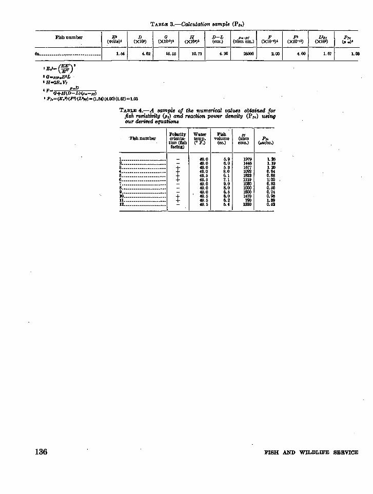
TABLE a.-Calculation sample (P,y)
FIsbDumber EO
ID G H D-L I Pu-PI
F F' Llpl P,.(voltS)1 (X10') (X10lO>' (X10'j2 (em;) ~ohmcm.> (X1o-e) , (X1O-II) (X106) (p .)"
---6a_________"__ , _________________
1.M I 4.62 10.55 10.71 4.20 I 28000 2.00 4.00 1.67 1.03,
(EE') IIEol- E"
I G~PIP.Dlt
I H~2R.l'l
'F- PuDG+H(D L)(P..-P/)
, P,,= (E.I) (FI) (Llp/) - (1.M) (4.00) (1.67) =1.03
TABLE 4.-A sample oj the numerical lJalues obtained Jorfish resistivity (PI) and reaction power density (P,y) 'UBingour derilJed equations
-Fish DumberPolarityorientation (flshfacing)
WaterteDlP.(0 F.)
Fishvolume
(ce.)
PI(ohmems.)
P,.(p.w/ce.)
136
-----_._--------------L _______ ~ _____ •_______
49.0 5.9 1979 1.262______________________ 49.0 6.0 1446 1.193__________• __• ________ + 49.0 5.3 1677 1.204_____• ________________ + 49.0 8.0 1092 0.945____________________._ + 49.5 6.1 1832 0.886______________________+ 49.5 7.1 1119 1:007______________________
49.0 9.0 1030 0.838_•__________•_________49.0 8.0 1000 0.509_.________________••__ 49.0 6.5 1800 0.7410_______________•_____ + 49.5 6.0 1470 0.96
11.______._._••••••_.__ + 49.5 6.2 790 1.3912_.___._._••••••••_.__ 49.5 5.4 1330 0.52
FISH AND WILDLIFE SERVICE