fivalco inc. - hassa yangın söndürme sistemleri · fivalco is a us company in our 25th year of...
TRANSCRIPT

Fivalco® Inc.

General Information
Fivalco is a US company in our 25th year of manufacturing Fire Protection Valves of uncompromising quality for our discerning customers.
All our products are FM or UL approved and most carry both UL and FM listings / approvals.
The latest edition of the NFPA code stated "products shall be listed or approved," without reference to either UL or FM although it is common practice for consultants to specify both a UL listing and a Factory Mutual approval.
UL listed means that the product has been tested, has passed all the stringent tests mandated by UL and is listed in the UL catalogue of Fire Protection Equipment
FM approved means that the product has passed all severe tests mandated by Factory Mutual and is approved by FM for use in building structures insured by Factory Mutual Insurance.
We, and all other manufacturers of similar products are subject to identical factory and product audit approvals and tests without compromise as the same approval and test criteria are applied to all producers of such products regardless of location.
All butterfly and gate valves are pressure tested for approval at 4 times the working pressure depending on valve size, and all valves must pass a cycling test of 1000 open/shut operations without failure of any part or component.
We take great care to make our products both attractive and functional and it is essential that our customers and end users do the same in order to maintain product integrity and proper function.
We draw your attention to minimum practices for handling and installation of our valves,at the end of this catalogue.
We are not content with making valves purely to meet mandatory specifications and have added quality and other features to stand out above the crowd.
All gate valves have Stainless Steel Stems for better corrosion resistance-our competitors use common brass.
All gate valves are painted true Fire Engine Red-RAL 3000-no on site painting needed.
All materials for Butterfly Valves are equal to or superior to our competitors
"The quality goes in before our name goes on"All written material in this catalogue is copyrighted and may not be produced in part or in whole without express written permission. Violators will be prosecuted.
Fivalco, Fireriser, Fireriser HP and Firefly are our registered Trade Marks.
Use of the trade marks without written permission is illegal and all violators will be prosecuted to the full extent of the law.
Fire Protection ProductsFivalco®
Fivalco® and Fireriser® are Registered Trade Marks Copyright Fivalco 2006
Product Index Approved and Listed Valves
FIRERISER® GATE VALVES 3299-300-FLA DUCTILE IRON RESILIENT OS&Y GATE VALVE FLANGED END................................................................1
3288-300-FLA DUCTILE IRON RESILIENT NRS GATE VALVES FLANGED END ...............................................................444
IP0888 VERTICAL INDICATOR POST ...................................................................................................................................7 WP0999 WALL TYPE INDICATOR POST ...............................................................................................................................8 INDICATOR POST ADJUSTMENT .........................................................................................................................................9
CHECK VALVES FIRE SWING CHECK 5201-300-FLA .....................................................................................................................................10 FIRE CHECK DCG GROOVED END ......................................................................................................................................11/12
FIRERISER® BUTTERFLY VALVES FIRERISER® HPW WAFER BUTTERFLY VALVE 300PSI ......................................................................................................13 FIRERISER® HPG GROOVED BUTTERFLY VALVE 300PSI ................................................................................................. FIRERISER® HPGT GROOVED/TAPPED BUTTERFLY VALVE 300PSI ................................................................................15 FIRERISER® DW WAFER BUTTERFLY VALVE 175PSI ........................................................................................................ FIRERISER® DG BUTTERFLY VALVE 175PSI ......................................................................................................................17 FIREFLY® BG BRONZE BUTTERFLY VALVE 175PSI ............................................................................................................18 FIREFLY® BT BRONZE BUTTERFLY VALVE 175PSI ............................................................................................................19
BUTTERFLY VALVES GROOVED BUTTERFLY VALVE BS TYPE ............................................................................................................................20 WAFER BUTTERFLY VALVE BS TYPE ..................................................................................................................................21
FIRERISER® Y-STRAINER FIRERISER® Y-STRAINER YS-300-FF ...................................................................................................................................22 FIRERISER® Y-STRAINER YS-300-FG ..................................................................................................................................23 FIRERISER® Y-STRAINER YS-300-GG..................................................................................................................................
BS5163 GATE VALVE BS5163 Gate Valve .................................................................................................................................................................25
FIRE HYDRANT FIRE Hydrant ...........................................................................................................................................................................
INSTALLATION GUIDE INSTALLATION GUIDE.......................................................................................................................................27/28/29/30/ 31
FLEXIBLE SPRINKLER CONNECTOR QUICKONNECT™FLEXIBLE SPRINKLER CONNECTOR .............................................................................................32/33
AIR VENT VALVES AUTOMATIC AIR VENT VALVE ..............................................................................................................................................
POTTER PRODUCT OUTSIDE SCREW AND YOKE VALVE SUPERVISORY SWITCH...............................................................................35/36/37 VANE TYPE WATERFLOW ALARM SWITCH WITH RETARD..........................................................................................38/39
FIVALCO INC LIMITED WARRANTY ...........................................................................................................................42
Fire Protection ProductsFivalco®
Fivalco® and Fireriser® are Registered Trade Marks Copyright Fivalco 2006
3299-300-FG DUCTILE IRON RESILIENT OS&Y GATE VALVE FLANGE-GROOVE END ................................................ 2 3299-300-GG DUCTILE IRON RESILIENT OS&Y GATE VALVE GROOVE-GROOVE END .............................................. 3
44444444 3288-300-FG DUCTILE IRON RESILIENT NRS GATE VALVES FLANGE-GROOVE END ................................................. 444 44444445
444 4444444 3288-300-FG DUCTILE IRON RESILIENT NRS GATE VALVES FLANGE-GROOVE END .................................................. 444 44444446
14
16
24
26
34
PRESSURE SWITCH PS10-2A(FM)...................................................................................................................................40/41
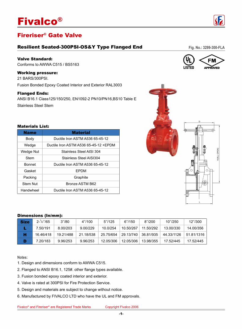
Fireriser® Gate Valve
Resilient Seated-300PSI-OS&Y Type Flanged End Fig. No.: 3299-300-FLA
Valve Standard: Conforms to AWWA C515 / BS5163
Working pressure: 21 BARS/300PSI.
Fusion Bonded Epoxy Coated Interior and Exterior RAL3003
Flanged Ends: ANSI B16.1 Class125/150/250, EN1092-2 PN10/PN16,BS10 Table E
Stainless Steel Stem
Materials List:Name Material
Body Ductile Iron ASTM A536 65-45-12
Wedge Ductile Iron ASTM A536 65-45-12 +EPDM
Wedge Nut Stainless Steel AISI 304
Stem Stainless Steel AISI304
Bonnet Ductile Iron ASTM A536 65-45-12
Gasket EPDM
Packing Graphite
Stem Nut Bronze ASTM B62
Handwheel Ductile Iron ASTM A536 65-45-12
Dimensions (In/mm):Size 2-1/2’’/65 3’’/80 4’’/100 5’’/125 6’’/150 8’’/200 10’’/250 12’’/300
L 7.50/191 8.00/203 9.00/229 10.0/254 10.50/267 11.50/292 13.00/330 14.00/356
H 16.46/418 19.21/488 21.18/538 25.75/654 29.13/740 36.81/935 44.33/1126 51.81/1316
D 7.20/183 9.96/253 9.96/253 12.05/306 12.05/306 13.98/355 17.52/445 17.52/445
Notes:1. Design and dimensions conform to AWWA C515.
2. Flanged to ANSI B16.1, 125#. other flange types available.
3. Fusion bonded epoxy coated interior and exterior.
4. Valve is rated at 300PSI for Fire Protection Service.
5. Design and materials are subject to change without notice.
6. Manufactured by FIVALCO LTD who have the UL and FM approvals.
-1-
Fivalco® and Fireriser® are Registered Trade Marks Copyright Fivalco 2006
Fivalco®

Fireriser® Gate Valve
Resilient Seated-300PSI-OS&Y Type Flange-Groove Ends Fig. No.: 3299-300-FG
Valve Standard: Conforms to AWWA C515 / BS5163
Working pressure: 21 BARS/300PSI.
Fusion Bonded Epoxy Coated Interior and Exterior RAL3003
Stainless Steel Stem
Materials List:Name Material
Body Ductile Iron A536 65-45-12
Wedge Ductile Iron EPDM Coated
Wedge Nut Stainless Steel AISI 304
Stem Stainless Steel AISI304/302
Bonnet Ductile Iron A536 65-45-12
Gasket EPDM
Packing Graphite Non-asbestos
Stem Nut Bronze ASTM B62
Handwheel Ductile Iron A536 65-45-12
Dimensions (In/mm):Size 2-1/2’’/65 3’’/80 4’’/100 5’’/125 6’’/150 8’’/200 10’’/250 12’’/300
L 7.50/191 8.00/203 9.00/229 10.00/254 10.50/267 11.50/292 13.00/330 14.00/356
H 16.46/418 19.21/488 21.18/538 25.75/654 29.13/740 36.81/935 44.33/1126 51.81/1316
D 7.20/183 9.96/253 9.96/253 12.05/306 12.05/306 13.98/355 17.52/445 17.52/445
Notes:1. Design and dimensions conform to AWWA C515.
2. Fusion bonded epoxy coated interior and exterior.
3. Valve is rated at 300PSI for Fire Protection Service.
Design and materials are subject to change without notice.
5. Manufactured by FIVALCO LTD who have the UL and FM approvals.
-2-
Fivalco® and Fireriser® are Registered Trade Marks Copyright Fivalco 2006
Fivalco®
2’’/50
7.00/178
16.46/418
7.20/183
Grooved Ends to suit ANSI/AWWA and BS Pipe
4.
ANSI B16.1 Class125/150/250, EN1092-2 PN10/PN16/PN25
Flanged Ends:
BS10 Table D/Table E

Fireriser® Gate Valve
Resilient Seated-300PSI-OS&Y Type Groove-Groove Ends Fig. No.: 3299-300-GG
Valve Standard: Conforms to AWWA C515 / BS5163
Working pressure: 21 BARS/300PSI.
Fusion Bonded Epoxy Coated Interior and Exterior RAL3003
Stainless Steel Stem
Materials List:Name Material
Body Ductile Iron A536 65-45-12
Wedge Ductile Iron EPDM Coated
Wedge Nut Stainless Steel AISI 304
Stem Stainless Steel AISI304/302
Bonnet Ductile Iron A536 65-45-12
Gasket EPDM
Packing Graphite Non-asbestos
Stem Nut Bronze ASTM B62
Handwheel Ductile Iron A536 65-45-12
Dimensions (In/mm):Size 2-1/2’’/65 3’’/80 4’’/100 5’’/125 6’’/150 8’’/200 10’’/250 12’’/300
L 7.50/191 8.00/203 9.00/229 10.0/254 10.50/267 11.50/292 13.00/330 14.00/356
H 16.46/418 19.21/488 21.18/538 25.75/654 29.13/740 36.81/935 44.33/1126 51.81/1316
D 7.20/183 9.96/253 9.96/253 12.05/306 12.05/306 13.98/355 17.52/445 17.52/445
Notes:1. Design and dimensions conform to AWWA C515.2. Fusion bonded epoxy coated interior and exterior.
3. Valve is rated at 300PSI for Fire Protection Service.4444444444Design and materials are subject to change without notice.
5. Manufactured by FIVALCO LTD who have the UL and FM approvals.
-3-
Fivalco® and Fireriser® are Registered Trade Marks Copyright Fivalco 2006
Fivalco®
2’’/50
7.00/178
16.46/418
7.20/183
Grooved Ends to suit ANSI/AWWA and BS Pipe
4.

Fireriser® Gate Valve
Resilient Seated-300PSI-NRS Type-Flanged End Fig No.: 3288-300-FLA
Valve Standard:Conforms to AWWA C515 / BS5163
Working pressure: 21 BARS/300PSI.
Fusion Bonded Epoxy Coated Interior and Exterior RAL3003
Flanged Ends: ANSI B16.1 Class125/150/250, EN1092-2 PN10/PN16/BS10 Table E
Stainless Steel Stem
Materials List:Name Material
Body Ductile Iron ASTM A536 65-45-12
Wedge Disc Ductile Iron ASTM A536 65-45-12 +EPDM
Disc Nut Bronze ASTM B62
Stem Stainless Steel AISI 304
Gasket EPDM
Bonnet Ductile Iron ASTM A536 65-45-12
Thrust Collar Bronze ASTM B62
Gland Ductile Iron ASTM A536 65-45-12
Wrench Nut Ductile Iron ASTM A536 65-45-12
Post Plate Ductile Iron ASTM A536 65-45-12
Dimensions (In/mm):Size 2-1/2’’/65 3’’/80 4’’/100 5’’/125 6’’/150 8’’/200 10’’/250 12’’/300
L 7.50/191 8.00/203 9.00/229 10.00/254 10.50/267 11.50/292 13.00/330 14.00/356
H 11.61/295 12.72/323 13.46/342 16.06/408 17.32/440 21.14/537 25.20/640 28.46/723
D 12.01/305 12.01/305 12.01/305 12.01/305 12.01/305 12.01/305 12.01/305 12.01/305
Notes:1. Stainless steel stem.
2. Design and dimensions conform to AWWA C515.
3. Flanged to ANSI B16.1, 125#. other flange types available.
4. Fusion bonded epoxy coated interior and exterior.
5. Valve is rated at 300PSI for Fire Protection Service.
6. Design and materials are subject to change without notice.
7. All valves Provided with 2"(50mm) operating Nut.
8. Manufactured by FIVALCO LTD who have the UL and FM approvals.
-4-
Fivalco® and Fireriser® are Registered Trade Marks Copyright Fivalco 2006
Fivalco®

Fireriser® Gate Valve
Resilient Seated-300PSI-NRS Type-Flange-Groove Ends Fig No.: 3288-300-FG
Valve Standard:Conforms to AWWA C515 / BS5163
Working pressure: 21 BARS/300PSI.
Fusion Bonded Epoxy Coated Interior and Exterior RAL3003
Stainless Steel Stem
Materials List:Name Material
Body Ductile Iron A536 65-45-12
Wedge Disc Ductile Iron EPDM Coated
Disc Nut Bronze ASTM B62
Stem Stainless Steel AISI 304/302
Gasket EPDM
Bonnet Ductile Iron A536 65-45-12
Thrust Collar Bronze ASTM B62
Gland Ductile Iron A536 65-45-12
Wrench Nut Ductile Iron A536 65-45-12
Post Plate Ductile Iron A536 65-45-12
Dimensions (In/mm):
Notes:1. Stainless steel stem.
2. Design and dimensions conform to AWWA C515.3. Fusion bonded epoxy coated interior and exterior.
4Valve is rated at 300PSI for Fire Protection Service.
5. Design and materials are subject to change without notice.
6666All valves Provided with 2"(50mm) operating Nut.7. Manufactured by FIVALCO LTD who have the UL and FM approvals.
-5-
Fivalco® and Fireriser® are Registered Trade Marks Copyright Fivalco 2006
Fivalco®
Size 2-1/2’’/65 3’’/80 4’’/100 5’’/125 6’’/150 8’’/200 10’’/250 12’’/300
L 7.50/191 8.00/203 9.00/229 10.00/254 10.50/267 11.50/292 13.00/330 14.00/356
H 12.72/323 16.06/408 17.32/440 21.14/537 25.20/640 28.46/723
D
2’’/50
7.00/178
11.61/295
12.01/305
11.61/295
12.01/305 12.01/30512.01/30512.01/30512.01/30512.01/30512.01/305 12.01/305
13.46/342
Grooved Ends to suit ANSI/AWWA and BS Pipe
4.
6.
ANSI B16.1 Class125/150/250, EN1092-2 PN10/PN16/PN25Flanged Ends:
BS10 Table D/Table E

Fireriser® Gate Valve
Resilient Seated-300PSI-NRS Type-Groove-Groove Ends Fig No.: 3288-300-GG
Valve Standard:Conforms to AWWA C515 / BS5163
Working pressure: 21 BARS/300PSI.
Fusion Bonded Epoxy Coated Interior and Exterior RAL3003
Stainless Steel Stem
Materials List:Name Material
Body Ductile Iron A536 65-45-12
Wedge Disc Ductile Iron EPDM Coated
Disc Nut Bronze ASTM B62
Stem Stainless Steel AISI 304/302
Gasket EPDM
Bonnet Ductile Iron A536 65-45-12
Thrust Collar Bronze ASTM B62
Gland Ductile Iron A536 65-45-12
Wrench Nut Ductile Iron A536 65-45-12
Post Plate Ductile Iron A536 65-45-12
Dimensions (In/mm):
Notes:1. Stainless steel stem.
2. Design and dimensions conform to AWWA C515.
3. Fusion bonded epoxy coated interior and exterior.44444444Valve is rated at 300PSI for Fire Protection Service.
5. Design and materials are subject to change without notice.6All valves Provided with 2"(50mm) operating Nut.
7. Manufactured by FIVALCO LTD who have the UL and FM approvals.
-6-
Fivalco® and Fireriser® are Registered Trade Marks Copyright Fivalco 2006
Fivalco®
Size 2-1/2’’/65 3’’/80 4’’/100 5’’/125 6’’/150 8’’/200 10’’/250 12’’/300
L 7.50/191 8.00/203 9.00/229 10.00/254 10.50/267 11.50/292 13.00/330 14.00/356
H 12.72/323 16.06/408 17.32/440 21.14/537 25.20/640 28.46/723
D
2’’/50
7.00/178
11.61/295
12.01/305
11.61/295
12.01/305 12.01/30512.01/30512.01/30512.01/30512.01/30512.01/305 12.01/305
13.46/342
Grooved Ends to suit ANSI/AWWA and BS Pipe
4.
6.

Materials List:No Name Qty Material1 Locking Wrench 1 ASTM A126B
2 Operating Nut 1 ASTM B62
3 Hex Nut Screw 2 ASTM A105
4 Hex Nut 2 ASTM A105
5 Snap Ring 1 AISI 066
6 Target Carrier Nut 1 ASTM B62
7 Target 4 ASTM B108
8 Hex Cap Nut 4 ASTM A105
9 Window Glass 2 LEXAN-UN
10 Window Glass Gasket 2 PTFE
11 Hex Cap Screw 4 ASTM A105
12 Hex Nut 4 ASTM A105
13 Body 1 ASTM A536
14 Hex Cap Screw 6 ASTM A105
15 Hex Nut 6 ASTM A105
16 Base Flange 1 ASTM A126B
17 Hex Cap Screw 4 ASTM A105
18 Hex Nut 4 ASTM A105
19 Crane Coupling 1 ASTM A536
20 Cotter Pin 1 AISI 304
21 Stand Pipe 1 ASTM A53
22 Stem 1 AISI A1045
23 Plug 1 AISI 304
24 Cover 1 ASTM A126B
25 Locking Nose 1 ASTM 307 B
Field Adjustment:1. Remove the top section from the top of the Indicator Post assembly.
2. Cut the required length off the bottom of the Standpipe for the Ground Line to match up with Standpipe Ground Line mark.
3. Set the "OPEN" and "SHUT" targets for the appropriate valve size.
4. Reattach the Top Section to the top of the Indicator Post assembly.
5. Design and dimensions are subject to change without notice.
6. Manufactured by FIVALCO LTD who have the UL and FM approvals.
Fireriser® Indicator Post
Fig. No: IP0888
-7-
Fivalco® and Fireriser® are Registered Trade Marks Copyright Fivalco 2006
Fivalco®
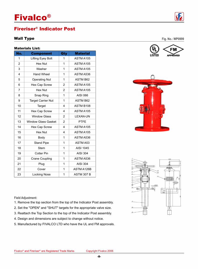
Fireriser® Indicator Post
Wall Type Fig. No.: WP0999
Materials List:No. Component Qty Material
1 Lifting Eyey Bolt 1 ASTM A105
2 Hex Nut 1 ASTM A105
3 Washer 1 ASTM A105
4 Hand Wheel 1 ASTM A536
5 Operating Nut 1 ASTM B62
6 Hex Cap Screw 2 ASTM A105
7 Hex Nut 2 ASTM A105
8 Snap Ring 1 AISI 066
9 Target Carrier Nut 1 ASTM B62
10 Target 4 ASTM B108
11 Hex Cap Screw 4 ASTM A105
12 Window Glass 2 LEXAN-UN
13 Window Glass Gasket 2 PTFE
14 Hex Cap Screw 4 ASTM A105
15 Hex Nut 4 ASTM A105
16 Body 1 ASTM A536
17 Stand Pipe 1 ASTM A53
18 Stem 1 AISI 1045
19 Cotter Pin 1 AISI 304
20 Crane Coupling 1 ASTM A536
21 Plug 1 AISI 304
22 Cover 1 ASTM A126B
23 Locking Nose 1 ASTM 307 B
Field Adjustment:1. Remove the top section from the top of the Indicator Post assembly.
2. Set the "OPEN" and "SHUT" targets for the appropriate valve size.
3. Reattach the Top Section to the top of the Indicator Post assembly.
4. Design and dimensions are subject to change without notice.
5. Manufactured by FIVALCO LTD who have the UL and FM approvals.
-8-
Fivalco® and Fireriser® are Registered Trade Marks Copyright Fivalco 2006
Fivalco®
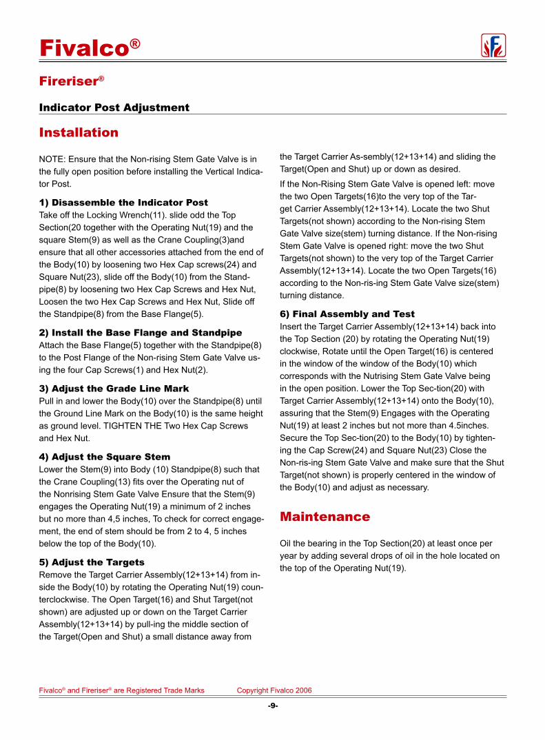
Fireriser®
Indicator Post Adjustment
Installation
NOTE: Ensure that the Non-rising Stem Gate Valve is in the fully open position before installing the Vertical Indica-tor Post.
1) Disassemble the Indicator PostTake off the Locking Wrench(11). slide odd the Top Section(20 together with the Operating Nut(19) and the square Stem(9) as well as the Crane Coupling(3)and ensure that all other accessories attached from the end of the Body(10) by loosening two Hex Cap screws(24) and Square Nut(23), slide off the Body(10) from the Stand-pipe(8) by loosening two Hex Cap Screws and Hex Nut, Loosen the two Hex Cap Screws and Hex Nut, Slide off the Standpipe(8) from the Base Flange(5).
2) Install the Base Flange and StandpipeAttach the Base Flange(5) together with the Standpipe(8) to the Post Flange of the Non-rising Stem Gate Valve us-ing the four Cap Screws(1) and Hex Nut(2).
3) Adjust the Grade Line MarkPull in and lower the Body(10) over the Standpipe(8) until the Ground Line Mark on the Body(10) is the same height as ground level. TIGHTEN THE Two Hex Cap Screws and Hex Nut.
4) Adjust the Square StemLower the Stem(9) into Body (10) Standpipe(8) such that the Crane Coupling(13) fits over the Operating nut of the Nonrising Stem Gate Valve Ensure that the Stem(9) engages the Operating Nut(19) a minimum of 2 inches but no more than 4,5 inches, To check for correct engage-ment, the end of stem should be from 2 to 4, 5 inches below the top of the Body(10).
5) Adjust the TargetsRemove the Target Carrier Assembly(12+13+14) from in-side the Body(10) by rotating the Operating Nut(19) coun-terclockwise. The Open Target(16) and Shut Target(not shown) are adjusted up or down on the Target Carrier Assembly(12+13+14) by pull-ing the middle section of the Target(Open and Shut) a small distance away from
the Target Carrier As-sembly(12+13+14) and sliding the Target(Open and Shut) up or down as desired.
If the Non-Rising Stem Gate Valve is opened left: move the two Open Targets(16)to the very top of the Tar-get Carrier Assembly(12+13+14). Locate the two Shut Targets(not shown) according to the Non-rising Stem Gate Valve size(stem) turning distance. If the Non-rising Stem Gate Valve is opened right: move the two Shut Targets(not shown) to the very top of the Target Carrier Assembly(12+13+14). Locate the two Open Targets(16) according to the Non-ris-ing Stem Gate Valve size(stem) turning distance.
6) Final Assembly and TestInsert the Target Carrier Assembly(12+13+14) back into the Top Section (20) by rotating the Operating Nut(19) clockwise, Rotate until the Open Target(16) is centered in the window of the window of the Body(10) which corresponds with the Nutrising Stem Gate Valve being in the open position. Lower the Top Sec-tion(20) with Target Carrier Assembly(12+13+14) onto the Body(10), assuring that the Stem(9) Engages with the Operating Nut(19) at least 2 inches but not more than 4.5inches. Secure the Top Sec-tion(20) to the Body(10) by tighten-ing the Cap Screw(24) and Square Nut(23) Close the Non-ris-ing Stem Gate Valve and make sure that the Shut Target(not shown) is properly centered in the window of the Body(10) and adjust as necessary.
Maintenance
Oil the bearing in the Top Section(20) at least once per year by adding several drops of oil in the hole located on the top of the Operating Nut(19).
-9-
Fivalco® and Fireriser® are Registered Trade Marks Copyright Fivalco 2006
Fivalco®

Valve Standard:Conforms to AWWA C508, Clear Waterway
Fusion bonded epoxy coated RAL3002
Working pressure:21 Bar / 300 PSI
Flanged Ends:ANSI B16.1 Class125/150/250,
EN1092-2 PN10/PN16/PN25
BS10 Table E
Materials ListPart Name Material ASTM Specification
Seat Ring Bronze ASTM B62
Plug Washer PTFE Commercial
Hinge Pin Stainless Stee AISI 304
Retainer Washer Bronze ASTM B62
Disc Ductile Iron A536 65-45-12
Clapper Arm Ductile Iron A536 65-45-12
Gasket EPDM Commercial
Cover Ductile Iron A536 65-45-12
Body Ductile Iron A536 65-45-12
Dimensions(mm/inch)
SIZEmm 50 65 80 100 125 150 200 250 300inch 2 21/2 3 4 5 6 8 10 12
Lmm 203 254 279 330 356 406 495 559 660inch 8 10 11 13 14 16 19.5 22 26
Hmm 122 133 136.5 162.5 296 298.5 357 410 465inch 4.80 5.23 5.37 6.40 11.65 11.75 14.06 16.14 18.31
Fireriser® Swing Check Valve
Resilient Seated 300PSI Flanged End Fig.No.:5201-300-FLA
2"~4"
5"~12"
L
H
L
H
-10-
Fivalco® and Fireriser® are Registered Trade Marks Copyright Fivalco 2006
Fivalco®

Fireriser® Grooved Check Valve
Specifications Working Pressure : 300 PSI (21 Bars)
Max. Test Pressure: 500 PSI (34.5 Bars)
Max. Working Temp : 250oF (120oC)
Primary Materials:Component Material
Body Ductile iron conforming toASTMA-536 epoxy coated
Color Red or black (optional)
Clapper
2"-5" type 304 or 302 stainlessSteel to ASTMA-167
6"-8" ductile iron conforming toASTMA-536, grade 65-45-12
Clapper FacingGrade E EPDM
-40oF to 230oF ( -40oC to 110oC)Service Temperature range
Seat RingType 304 stainless steel to ASTMA-123 ASTMA-213
ASTMA-312 or ASTMA-269
Spring Type 302 stainless steel to ASTMA-313
Hinge Pin Type 304 or 302 stainless steel toASTMA-580
Hinge Pin Bushings Sintered bronze to ASTMB-438
Flow Date-Friction Los (Ft. Pipe)Valves Pipe C=100 C=120
Size OD Sch.10 Sch.30 Sch.40 Sch.10 Sch.30
Sch.40
In/mm In/mm Ft/m Ft/m Ft/m Ft/m Ft/m Ft/m
2 2.375 10 -- 8 14 -- 11
50 60.3 3.0 --- 2.4 4.3 ---- 3.4
2-1/2 2.875 14 -- 10 20 -- 15
65 73.0 4.3 --- 3.0 6.1 --- 4.6
3 3.500 17 -- 12 23 -- 17
80 88.9 5.2 --- 3.7 7.0 -- 5.5
4 4.500 17 -- 13 23 -- 18
100 114.3 5.2 --- 4.0 7.0 -- 5.5
5 5.562 14 -- 11 20 -- 15
125 141.3 4.3 --- 3.4 6.1 --- 4.6
6 6.625 23 -- 19 33 -- 26
150 168.3 7.0 --- 5.8 10.1 --- 7.9
8 8.625 35 32 30 50 43 43
200 21.9 10.7 9.6 9.1 15.2 13.1 13.7
Fig.No.:DCG
-11-
Fivalco® and Fireriser® are Registered Trade Marks Copyright Fivalco 2006
Fivalco®

Highriser® Grooved Check ValveGrooved Check Valves,UL.ULC Listed/FM Approved Grooved End, Size: 2-1/2", 3", 4", 6" and 8"
WORKING PRESSURE 300PSI/21BARSThe Check Valve is a compact, cost effective valve offering low pressure-drop, non-slam performance the Check valve assem-bly is lighter and fast to install, and costs less than flanged and wafer valve assemblies. In the fully-open position the clapper is held tightly against the valve body, out of the flow stream, to pro-vide maximum flow area and prevention of clapper flutter. The clapper design produces quick, non-slam closure before flow reversal can occur, while meeting FM requirements for an anti-water hammer valve rating. Each valve is hydrostatically tested for leak tightness to 500 PSI. The clapper-seat design permits leak free sealing of back pressures in service conditions ranging from 300 PSI to as low as 5 P I
Fig.No:DCG
-12-
Fivalco® and Fireriser® are Registered Trade Marks Copyright Fivalco 2006
Fivalco®

Specifications Universal wafer Type Butterfly Valve Suitable for Connecting to ANSI B 16 Class 125, ISO 2084/Din 2501 PN 16 & BS 4504 PN 16 Flanges
Working Pressure: 300 PSI (21Bars)
Max.Test Pressure: 600 PSI (42.8 Bars)
Max.Working Temp: 250oF (120oC)
Factory installed UL, listed double Tamper Switches
Valve Approved For Indoor and Outdoor Use
Primary Materials:
Component MaterialBody ASTM A-536 Nylon-11 Coated
Disc ASTM B-536 EPDM Encapsulated
Upper&Lower Stems AISI 420-SS
Worn Gear Shaft AISI 410-SS
Housing ASTM A-536
Hand Wheel ASTM A-536
Flag Indicator ASTM A-536
Shear Pin ASTM A-510
Segment Gear ASTM B-148 or B-548
HousingGasket EPDM Grade"E"
O-Rings (All) EPDM Grade"E"
Dimensions (mm/in):Size In/mm A B C D E F G H
2-1/2"/65 5.39(136) 3.43(87) 1.81(46) 5.89(149.4) 6.54(166) 5.31(135) 5.04(128) 0.32(8.2)
3"/80 5.63(143) 3.66(93) 1.81(46) 6.62(168.2) 6.81 (173) 5.31(135) 5.04(128) 0.57(4.9)
4”/100 6.14(156) 4.29(107) 2.06(52) 7. 89(200.2) 7.32(186) 5.31(135) 5.04(128) 0.89(22.7)
6"/150 7.4(188) 5.67(144) 2.20(56) 10.6(269.8) 8.58(218) 8.66(193) 8.66(222) 1.79(44.4)
8"/200 8.7(222) 6.54(166) 2.28(58) 13.0(330.2) 9.92 (252) 8.66(193) 8.66(222) 2.72(69.1)
Fireriser® Butterfly ValveWafer Type Butterfly Valves, UL, ULC Listed/FM Approved Wafer Type, Sizes: 2-1/2", 3", 4", 6" and 8" Fig.No:HPW
-13-
Fivalco® and Fireriser® are Registered Trade Marks Copyright Fivalco 2006
Fivalco®

Fireriser® Butterfly Valve
Grooved Butterfly Valves, UL、ULC Listed/FM Approved
Specifications Working Pressure: 300 PSI (21Bars)
Max.Test Pressure: 600 PSI (42.8 Bars)
Max.Working Temp: 250oF (120oC)
Factory installed UL, listed double Tamper Switches
Valve Approved For Indoor and Outdoor Use
Primary Materials:
Component MaterialBody ASTM A-536 Nylon-11 Coated
Disc ASTM B-536 EPDM Encapsulated
Upper&Lower Stems AISI 420-SS
Worn Gear Shaft AISI 410-SS
Housing ASTM A-536
Hand Wheel ASTM A-536
Flag indicator ASTM A-536
Shear Pin ASTM A-510
Segment Gear EPDM Grade"E" ASTM B-148 or B-584
Housing Gasket EPDM Grade"E"
O-Rings (All) EPDM Grade"E"
Dimensions(mm/inch):
Size In/mm A B C D E F G H
2-1/2"/65 4.1(106) 3.3(85) 3.80(96.4) 2.8(73.0) 5.31(136) 5.04(128) 5.04(128)
3"/80 4.4(112) 3.6(92) 3.80(96.4) 3.50(83.9) 5.99 (142) 5.04(128) 5.04(128)
4”/100 5.7(145) 4.34(108) 4.54(115.4) 4. 50(114.3) 6.89(173) 5.04(128) 5.04(128)
6"/150 7.1(180) 5.7(146) 5.21(132.4) 6.6(168.3) 8.23(209) 8.66(220) 8.66(220) 0.28(7.10)
8"/200 8.0(204) 6.7(170) 5.80(147.4) 8.63(219.1) 9.21 (234) 8.66(220) 8.66(220) 0.9(24.0)
Fig.No.:HPG
-14-
Fivalco® and Fireriser® are Registered Trade Marks Copyright Fivalco 2006
Fivalco®
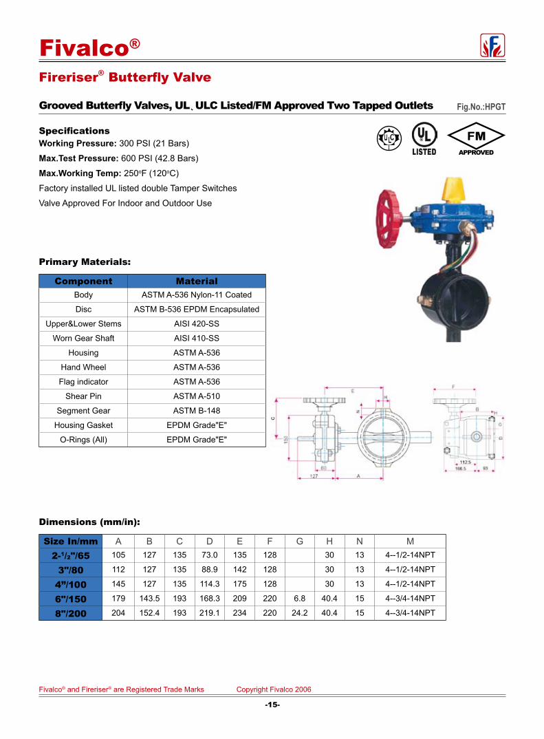
Fireriser® Butterfly Valve
Grooved Butterfly Valves, UL、ULC Listed/FM Approved Two Tapped Outlets
Primary Materials:
Component MaterialBody ASTM A-536 Nylon-11 Coated
Disc ASTM B-536 EPDM Encapsulated
Upper&Lower Stems AISI 420-SS
Worn Gear Shaft AISI 410-SS
Housing ASTM A-536
Hand Wheel ASTM A-536
Flag indicator ASTM A-536
Shear Pin ASTM A-510
Segment Gear ASTM B-148
Housing Gasket EPDM Grade"E"
O-Rings (All) EPDM Grade"E"
Dimensions (mm/in):
Size In/mm A B C D E F G H N M2-1/2"/65 105 127 135 73.0 135 128 30 13 4--1/2-14NPT
3"/80 112 127 135 88.9 142 128 30 13 4--1/2-14NPT
4”/100 145 127 135 114.3 175 128 30 13 4--1/2-14NPT
6"/150 179 143.5 193 168.3 209 220 6.8 40.4 15 4--3/4-14NPT
8"/200 204 152.4 193 219.1 234 220 24.2 40.4 15 4--3/4-14NPT
Specifications Working Pressure: 300 PSI (21 Bars)
Max.Test Pressure: 600 PSI (42.8 Bars)
Max.Working Temp: 250oF (120oC)
Factory installed UL listed double Tamper Switches
Valve Approved For Indoor and Outdoor Use
Fig.No.:HPGT
-15-
Fivalco® and Fireriser® are Registered Trade Marks Copyright Fivalco 2006
Fivalco®

Primary Materials:
Component MaterialBody ASTM A-536 EMPE Encapsulated
Disc ASTM B-548 or B-148
Upper&Lower Stems AISI 420-SS
Worn Gear Shaft AISI 410-SS
Housing ASTM A-536
Hand Wheel ASTM A-536
Flag indicator ASTM A-536
Shear Pin ASTM A-510
Segment Gear ASTM B-148
Housing Gasket EPDM Grade"E"
O-Rings (All) EPDM Grade"E"
SpecificationsUniversal wafer Type Butterfly Valve Suitable for Connecting to ANSI B 16 Class 125, ISO 2084/Din 2501 PN 16 & BS 4504 PN 16 Flanges
Working Pressure: 175 PSI (12.5 Bars)
Max.Test Pressure: 350 PSI (25.0 Bars)
Max.Working Temp: 250oF (120oC)
Factory installed UL, listed double Tamper Switches
Valve Approved For Indoor and Outdoor Use
Dimensions(mm/inch):
Size In/mm A B C D E F G H
2-1/2"/65 4.1(106) 3.3(85) 1.8(46) 3.6(92) 5.3(135) 5.3(135) 4.9(125) 0.4(9.5)
3"/80 4.4(112) 3.6(92) 1.8(46) 4.2(107) 5.6 (142) 5.3(135) 4.9(125) 0.6(16)
4”/100 5.7(145) 4.34(108) 2.0(52) 5. 0(128) 6.9(175) 5.3(135) 4.9(125) 1.0(25)
6"/150 7.1(180) 5.7(146) 2.2(56) 7. 1(181) 8.3(210) 7.6(193) 8.9(225) 1.8(45.3)
8"/200 8.0(204) 6.7(170) 2.4(60) 9.2(234) 9.1 (232) 7.6(193) 8.9(225) 2.7(68.5)
Fireriser® Butterfly ValveWafer Type Butterfly Valves,UL,ULC Listed/FM Approved DW Wafer Type,Size: 2-1/2", 3", 4", 6", 8" Fig.No.:DW
-16-
Fivalco® and Fireriser® are Registered Trade Marks Copyright Fivalco 2006
Fivalco®
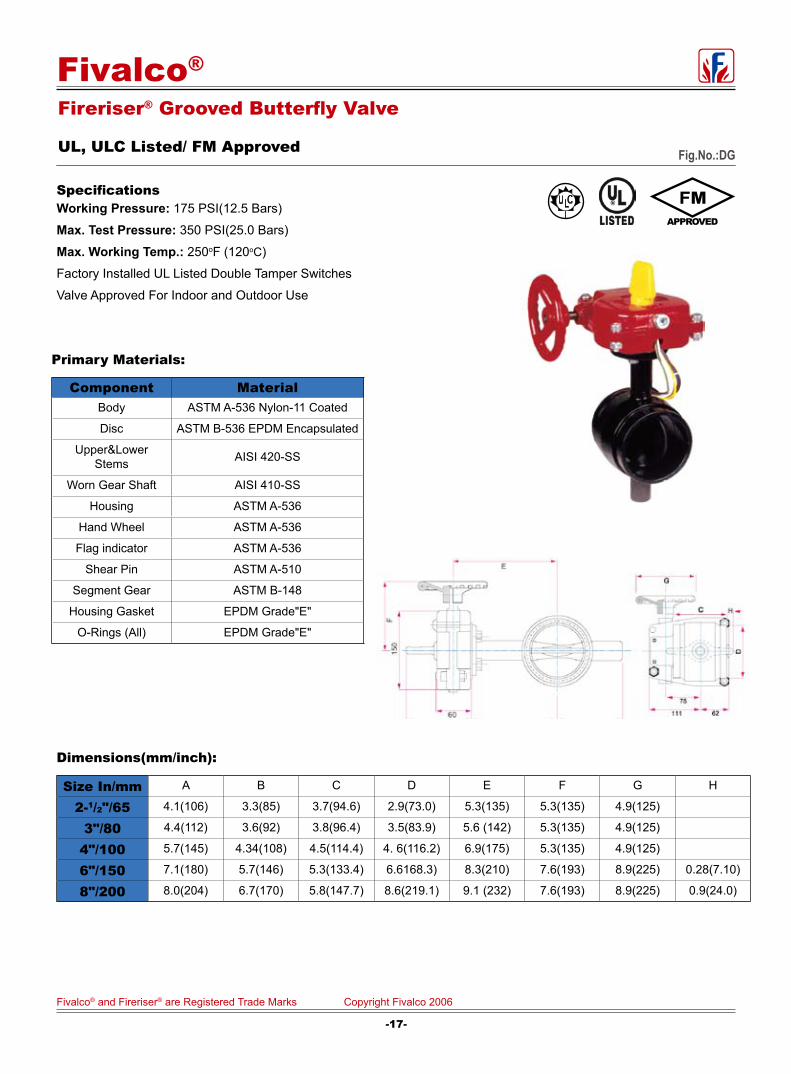
Fireriser® Grooved Butterfly Valve
UL, ULC Listed/ FM Approved
SpecificationsWorking Pressure: 175 PSI(12.5 Bars)
Max. Test Pressure: 350 PSI(25.0 Bars)
Max. Working Temp.: 250oF (120oC)
Factory Installed UL Listed Double Tamper Switches
Valve Approved For Indoor and Outdoor Use
Primary Materials:
Component MaterialBody ASTM A-536 Nylon-11 Coated
Disc ASTM B-536 EPDM Encapsulated
Upper&Lower Stems AISI 420-SS
Worn Gear Shaft AISI 410-SS
Housing ASTM A-536
Hand Wheel ASTM A-536
Flag indicator ASTM A-536
Shear Pin ASTM A-510
Segment Gear ASTM B-148
Housing Gasket EPDM Grade"E"
O-Rings (All) EPDM Grade"E"
Dimensions(mm/inch):
Size In/mm A B C D E F G H
2-1/2"/65 4.1(106) 3.3(85) 3.7(94.6) 2.9(73.0) 5.3(135) 5.3(135) 4.9(125)
3"/80 4.4(112) 3.6(92) 3.8(96.4) 3.5(83.9) 5.6 (142) 5.3(135) 4.9(125)
4"/100 5.7(145) 4.34(108) 4.5(114.4) 4. 6(116.2) 6.9(175) 5.3(135) 4.9(125)
6"/150 7.1(180) 5.7(146) 5.3(133.4) 6.6168.3) 8.3(210) 7.6(193) 8.9(225) 0.28(7.10)
8"/200 8.0(204) 6.7(170) 5.8(147.7) 8.6(219.1) 9.1 (232) 7.6(193) 8.9(225) 0.9(24.0)
Fig.No.:DG
-17-
Fivalco® and Fireriser® are Registered Trade Marks Copyright Fivalco 2006
Fivalco®

Firefly® Butterfly ValveBronze Butterfly Valve, UL, ULC Listed/FM ApprovedBG Grooved End, Size: 2" and 2-1/2" Fig.No.:BG
SpecificationsWorking Pressure: 175 PSI (12.5 Bars)
Max.Working Temp: 250oF (120)
Factory Installed UL Listed Double Tamper Switches
Valve Approved For Indoor and Outdoor Use
Primary Materials:Component Material
Body SS304
Disc ASTM B-548 EPDM Encapsulated
Upper Stem ASTM A-564 Type XM12
Lower Stem ASTM A-564 Type XM12
Gear Housing Cover ASTM A-619
Hand Wheel ASTM A-619
Flag Indicator ASTM B-16
Yoke Mechanism ASTM A-283
Stem Bushing ASTM B-16
Conduit Connector ASTM A-307
O-Rings EPDM Grade"E"
Cover Gasket NBR
Dimensions:Size in/mm A B C D E F G
2"/50 4.56(114) 2.41(60.3) 2.29(57.15) 0.64(16) 0.32(8) 1.96(49) 3.62(90.5)
2-1/2"/65 4.56(114) 3.0(75) 2.75(69.1) 0.64(16) 0.32(8) 2.18(54.5) 3.82(95.5)
Patent Pending.
-18-
Fivalco® and Fireriser® are Registered Trade Marks Copyright Fivalco 2006
Fivalco®

G
F
Firefly® Butterfly ValveBronze Butterfly Valves, UL, ULC Listed/FM Approved BT Size: 1", 1-1/4", 1-1/2", 2" and 2-1/2" Fig.No.:BT
Primary Materials: Component Material
Body ASTM B-506
Disc ASTM B-548 EPDM Encapsulated
Upper Stem ASTM A-564 Type XM12
Lower Stem ASTM A-564 Type XM12
Gear Housing Cover ASTM A-619
Hand Wheel ASTM A-619
Flag indicator ASTM B-16
Yoke Mechanism ASTM A-283
Stem Bushing ASTM B-16
Conduit Connector ASTM A-307
O-Rings (All) EPDM Grade"E"
Cover Gasket NBR
SpecificationsWorking Pressure: 175 PSI (12.5 Bars)
Max. Working Temp: 250。F (120)
Factory installed UL Listed Double Tamper Switches Valve Approved
For indoor and Outdoor Use.
Dimensions (Inch/mm)Size in/mm A B C D E F G
1”/25 1.75 (43.7) 1.56 (39.7) 2.16 (54) 2.08 (52) 1.48 (52) 43 34
1-1/4” 32 2.16 (54) 196 (47) 2.68 (67) 2.24 (56) 1.64 (41) 47 47
1-1/2” 40 2.4 (60) 2.24 (70) 2.92 (73) 2.36 (90) 2.45 (61.3) 50 48.6
2”/50 2.8 (70) 2.8 (70) 3.3 (82.4) 2.56 (54) 1.96 (49) -- --
2-1/2”/65 3.6 (90) 3.36 (84) 4.16 (104) 2.78 (69.5) 2.18 (54.5) -- --
C
-1*9-
Fivalco® and Fireriser® are Registered Trade Marks Copyright Fivalco 2006
Fivalco®

Grooved Butterfly Valve
PN20/300PSI Fig.No.:1352
Valve Standards: Complies with EN593/BS5155/MSS SP-67.
Working Pressure and Temperature:Working pressure PN20/300PSI.
Temperature from -10 to 100 for EPDM coated disc.
Temperature from -10 to 82 for NBR coated disc.
Top Flange: Complies with ISO5211/1.
End-To-End:Dimensions according to MSS SP-67-2002
Grooved Type:Grooved dimensions comply with Metric or ANSI Pipe Standards.
Operator:Gear operator. With two internal CE approved switches.
Materials Specifications:Part Name Material EN Spec. ASTM Spec.
Body Ductile Iron EN-JS1050 A536 65-45-12
Shaft Stainless Stee BS970 420S37 AISI 416
DiscDI EPDM Coated EN-JS1050 A536 65-45-12
DI NBR Coated EN-JS1050 A536 65-45-12
Bushing PTFE Commercial Commercial
O-Ring EPDM/NBR Commercial Commercial
Dimensions (mm/In)Size 50/2" 65/2.5" 80/3" 100/4" 125/5" 150/6" 200/8" 250/10" 300/12"
A 100.5 107 114.5 135 148.5 169 198 228.5 266
B 62 73/75 81 97 114 129 159 191 222
C1 201.5 208 215.5 236 249.5 270 299 329.5 367
C2 261.5 268 275.5 296 309.5 330 359 389.5 427
Pipe OD 60.3 73/76.1 88.9 114.3 139.7/141.3 165.1/168.3 219.1 273 323.9
E 147 147 147 147 147 147 147 197 197
F 50 50 50 59 72 85.5 112 138 164
G 71.5 71.5 71.5 71.5 71.5 71.5 71.5 75 75
H 109 109 109 109 109 145 145 166 166
L 81 96 96 116 147.6 148 135 159 165
P 70 70 70 70 70 70 70 102 102
-20-
Fivalco® and Fireriser® are Registered Trade Marks Copyright Fivalco 2006
Fivalco®
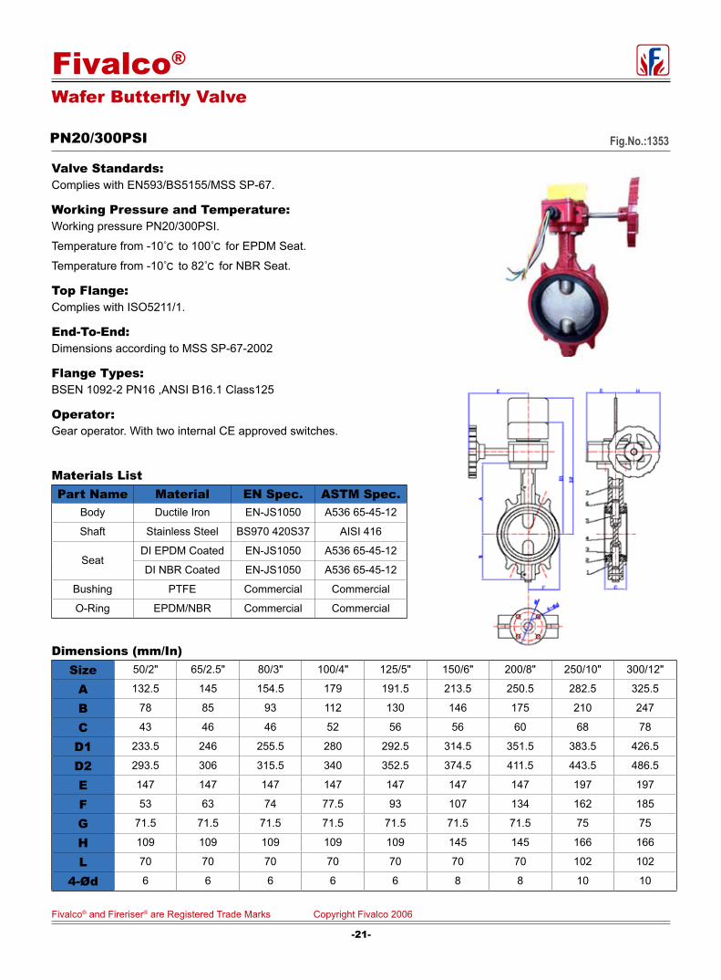
Wafer Butterfly Valve
PN20/300PSI Fig.No.:1353
Valve Standards: Complies with EN593/BS5155/MSS SP-67.
Working Pressure and Temperature:Working pressure PN20/300PSI.
Temperature from -10 to 100 for EPDM Seat.
Temperature from -10 to 82 for NBR Seat.
Top Flange: Complies with ISO5211/1.
End-To-End:Dimensions according to MSS SP-67-2002
Flange Types:BSEN 1092-2 PN16 ,ANSI B16.1 Class125
Operator:Gear operator. With two internal CE approved switches.
Materials ListPart Name Material EN Spec. ASTM Spec.
Body Ductile Iron EN-JS1050 A536 65-45-12
Shaft Stainless Steel BS970 420S37 AISI 416
SeatDI EPDM Coated EN-JS1050 A536 65-45-12
DI NBR Coated EN-JS1050 A536 65-45-12
Bushing PTFE Commercial Commercial
O-Ring EPDM/NBR Commercial Commercial
Dimensions (mm/In)Size 50/2" 65/2.5" 80/3" 100/4" 125/5" 150/6" 200/8" 250/10" 300/12"
A 132.5 145 154.5 179 191.5 213.5 250.5 282.5 325.5
B 78 85 93 112 130 146 175 210 247
C 43 46 46 52 56 56 60 68 78
D1 233.5 246 255.5 280 292.5 314.5 351.5 383.5 426.5
D2 293.5 306 315.5 340 352.5 374.5 411.5 443.5 486.5
E 147 147 147 147 147 147 147 197 197
F 53 63 74 77.5 93 107 134 162 185
G 71.5 71.5 71.5 71.5 71.5 71.5 71.5 75 75
H 109 109 109 109 109 145 145 166 166
L 70 70 70 70 70 70 70 102 102
4-Ød 6 6 6 6 6 8 8 10 10
-21-
Fivalco® and Fireriser® are Registered Trade Marks Copyright Fivalco 2006
Fivalco®

Fireriser® Y Strainer
Fig.No.:YS-300 - FF
Component Materia SpecificationBody Ductile ron A536 65-45-12
Cover Ductile Iron A536 65-45-12
Screen Stainless Steel AISI 304
Gasket EPDM
Plug Carbon Steel
Fusion bonded epoxy coated RAL3003
Working pressure21 Bar/ 300 PSI
Flanged EndsANSI B16.1 Class125/150/250,
EN1092-2 PN10/PN16/PN25
BS10 Table D/Table E
Materials List
H1
PLUG 3/4"
H
LH
1
PLUG 3/4"
H
L
Dimensions(mm/inch)
SIZEmm 50 65 80 100 125 150 200 250 300
inch 2" 21/2" 3" 4" 5" 6" 8" 10" 12"
Lmm 203 254 260 308 398 472 550 654 762
inch 7.99" 10" 10.24" 12.13" 15.67" 18.58" 21.65" 25.75" 30"
Hmm 132 158 175 202 290 334 391 460 590
inch 5.20" 6.22" 6.89" 7.99" 11.42" 13.15" 15.39" 18.11" 23.23"
H1mm 195 240 270 320 425 495 570 700 840
inch 7.68" 9.45" 10.63" 12.60" 16.73" 19.49" 22.44" 27.56" 33.07"
SizeIn/mm
Measured Loss at 15 fps (4.6m/s)
2”/50 7.22 psi
2.5”/65 5.89psi
3”/80 8.24psi
4”/100 5.88psi
5”/125 7.63psi
6”/150 4.82psi
8”/200 5.83psi
10”/250 7.25psi
12”/300 5.73psi
-22-
Fivalco® and Fireriser® are Registered Trade Marks Copyright Fivalco 2006
Fivalco®

Fusion bonded epoxy coated RAL3003
Working pressure21 Bar/ 300 PSI
Flanged By Grooved EndANSI B16.1 Class125/150/250,EN1092-2 PN10/PN16/PN25
BS10 Table D/Table E
AWWA C 606
Grooved Ends To Suit ANSI Or BS Standard Pipe
Materials ListComponent Materia Specification
Body Ductile Iron A536 65-45-12
Cover Ductile Iron A536 65-45-12
Screen Stainless Steel AISI 304
Gasket EPDM
Plug Carbon Steel
imensions(mm/inch)
SIZEmm 50 65 80 100 125 150 200 250 300
inch 2" 21/2" 3" 4" 5" 6" 8" 10" 12"
Lmm 203 254 260 308 398 472 550 654 762
inch 8" 10" 10.24" 12.13" 15.67" 18.58" 21.65" 25.75" 30"
Hmm 130 158 175 202 290 334 391 460 590
inch 5.12" 6.22" 6.89" 7.95" 11.42" 13.15" 15.39" 18.11" 23.23"
H1mm 195 240 270 320 425 495 570 700 840
inch 7.68" 9.45" 10.63" 12.60" 16.73" 19.49" 22.44" 27.56" 33.07"
ODmm 60.3 73.0/76.1 88.9 114.3 139.7/141.3 165.1/168.3 219.1 273 323.9
inch 2.37" 2.87/3" 3.50" 4.5" 5.5/5.56" 6.5/6.63" 8.63" 10.75" 12.75"
SizeIn/mm
Measured Loss at 15 fps (4.6m/s)
2”/50 7.22 psi
2.5”/65 5.89psi
3”/80 8.24psi
4”/100 5.88psi
5”/125 7.63psi
6”/150 4.82psi
8”/200 5.83psi
10”/250 7.25psi
12”/300 5.73psi
Fireriser® Y Strainer
Fig.No.:YS-300-FG
-23-
Fivalco® and Fireriser® are Registered Trade Marks Copyright Fivalco 2006
Fivalco®
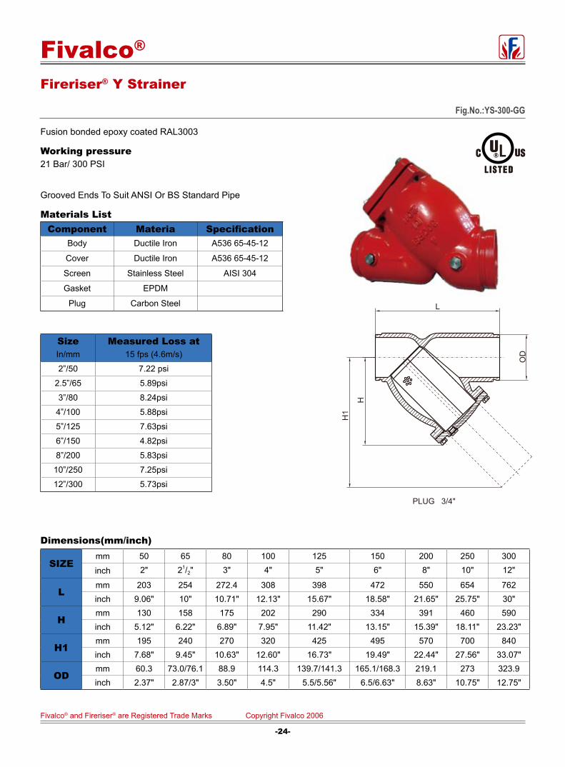
Fig.No.:YS-300-GG
Fireriser® Y Strainer
Fusion bonded epoxy coated RAL3003
Working pressure21 Bar/ 300 PSI
Grooved Ends To Suit ANSI Or BS Standard Pipe
Materials ListComponent Materia Specification
Body Ductile Iron A536 65-45-12
Cover Ductile Iron A536 65-45-12
Screen Stainless Steel AISI 304
Gasket EPDM
Plug Carbon Steel
Dimensions(mm/inch)
SIZEmm 50 65 80 100 125 150 200 250 300
inch 2" 21/2" 3" 4" 5" 6" 8" 10" 12"
Lmm 203 254 272.4 308 398 472 550 654 762inch 9.06" 10" 10.71" 12.13" 15.67" 18.58" 21.65" 25.75" 30"
Hmm 130 158 175 202 290 334 391 460 590inch 5.12" 6.22" 6.89" 7.95" 11.42" 13.15" 15.39" 18.11" 23.23"
H1mm 195 240 270 320 425 495 570 700 840inch 7.68" 9.45" 10.63" 12.60" 16.73" 19.49" 22.44" 27.56" 33.07"
ODmm 60.3 73.0/76.1 88.9 114.3 139.7/141.3 165.1/168.3 219.1 273 323.9inch 2.37" 2.87/3" 3.50" 4.5" 5.5/5.56" 6.5/6.63" 8.63" 10.75" 12.75"
OD
H1
PLUG 3/4"
H
L
SizeIn/mm
Measured Loss at 15 fps (4.6m/s)
2”/50 7.22 psi
2.5”/65 5.89psi
3”/80 8.24psi
4”/100 5.88psi
5”/125 7.63psi
6”/150 4.82psi
8”/200 5.83psi
10”/250 7.25psi
12”/300 5.73psi
-24-
Fivalco® and Fireriser® are Registered Trade Marks Copyright Fivalco 2006
Fivalco®
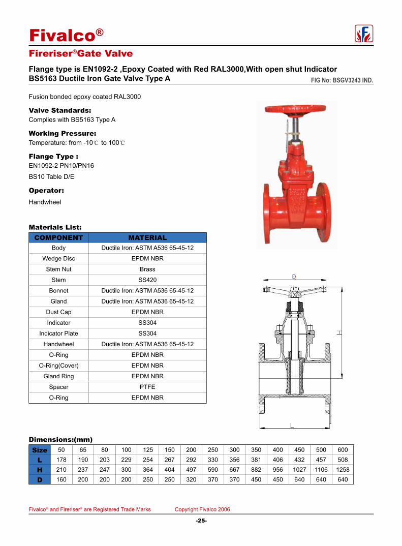
Fusion bonded epoxy coated RAL3000
Valve Standards: Complies with BS5163 Type A
Working Pressure: Temperature: from -10 to 100
Flange Type : EN1092-2 PN10/PN16
BS10 Table D/E
Operator: Handwheel
Materials List:COMPONENT MATERIAL
Body Ductile Iron: ASTM A536 65-45-12
Wedge Disc EPDM NBR
Stem Nut Brass
Stem SS420
Bonnet Ductile Iron: ASTM A536 65-45-12
Gland Ductile Iron: ASTM A536 65-45-12
Dust Cap EPDM NBR
Indicator SS304
Indicator Plate SS304
Handwheel Ductile Iron: ASTM A536 65-45-12
O-Ring EPDM NBR
O-Ring(Cover) EPDM NBR
Gland Ring EPDM NBR
Spacer PTFE
O-Ring EPDM NBR
Dimensions:(mm)Size 50 65 80 100 125 150 200 250 300 350 400 450 500 600
L 178 190 203 229 254 267 292 330 356 381 406 432 457 508
H 210 237 247 300 364 404 497 590 667 882 956 1027 1106 1258
D 160 200 200 200 250 250 320 370 370 450 450 640 640 640
Fireriser®Gate ValveFlange type is EN1092-2 ,Epoxy Coated with Red RAL3000,With open shut IndicatorBS5163 Ductile Iron Gate Valve Type A FIG No: BSGV3243 IND.
-25-
Fivalco® and Fireriser® are Registered Trade Marks Copyright Fivalco 2006
Fivalco®

Fire Hydrant DN80
BS 750 Type II
Materials List:Item Part Name Material BS Spec.
1 Body Ductile Iron EN-JS1050
2 Bolt Stainless Steel 970 304S15
3 Holder Stainless Steel 970 304S15
4 Gasket EPDM/NBR
5 Disc Ductile Iron EN-JS1050
6 Stem Nut Brass 2874 CZ121
7 Screw EPDM/NBR
8 Stem Ductile Iron EN-JS1050
9 O-Ring EPDM/NBR
10 Cover Ductile Iron EN-JS1050
11 Washer Brass 2874 CZ121
12 O-Ring EPDM/NBR
13 Cap Gasket Plastic
14 Driver Cap Ductile Iron EN-JS1050
15 Bolt Stainless Steel 970 304S15
16 Indicator Cap Plastic
17 Bolt Stainless Steel 970 304S15
18 Washer Stainless Steel 970 304S15
19 Dust Cap Plastic
20 Outlet Bronze 1400 LG2
21 O-Ring EPDM/NBR
22 Rope Stainless Steel
23 Plug Plastic
Notes:1. Inlet flange is DN80 drilled to EN1092-2 PN 10, PD 16 and ANSI B16.1 Class 125
2. Standard outlet is 2-1/2" London tound Thread.
Other outlets available-Birmingham, Belfast, or instantaneous. Specify on order.
3. Hydrostatic test: Body-24Bars, Seat-17.6 Bars
4. Minimum 200 microns Fusion Bonded Epoxy coating for protection against corrosion.
Fig. 9207
-26-
Fivalco® and Fireriser® are Registered Trade Marks Copyright Fivalco 2006
Fivalco®

Fivalco®
Design Requirements
Installation
Care & Maintenance
Fireriser® Installation Guide
The Fivalco grooved butterfly valve should be connected to the piping system with aproved couplings or flange adapters. Flow may be from either direction, and the valve may be positioned in any direction.
Fivalco butterfly valves have been designed with a slow close hand wheel operator which effectively minimizes water hammer. These valves feature minimum flow restriction and pressure loss when in the fully open position.
When the valves are received from the manufacture they should be handled carefully to avoid breakage and damage to the seating area. Before installation of the valve, clean piping, flange and couping. When the valve closes hard, it is usually due to debris lodged in the sealing area. Often this may be corrected by backing off the hand wheel and closing again.
The valve should never be forced to seat by applying a wrench to the hand wheel as this may distort the valve componects or score the sealing surface. The use of excessive force to open or close the valve violates all warranties whether express or implied.
The inlet and outlet pipe adjacent to the valve should be properly supported to prevent excessive stress on the valve body. The valve should not be used to force a pipeline into position as this may result in distortion of the valve body.
Conduit and elecrical connections to the optional tamper switch must be in accordance with National Electrical Code(NFPA 72)and/or requirements of the local authority having jurisdiction.
Fivalco butterfly valves require no regular maintenance, however, it is advisable to inspect and verify proper operation of the unit annually or in accordance with the authorty having jurisdiction.The inspection should include a visual check for leakage at the valve pipe connection and body to operator connection.
Inspection and maintenance should be performed by a qualified inspection service.
-27-
Fivalco® and Fireriser® are Registered Trade Marks Copyright Fivalco 2006
Fivalco®

Switch Installaion Fivalco butterfly valves are provided with internal supervisory position switches. The tamper switch operates by a cam connected to the vallve stem. The switch will change positon and close within two(2) full turns of the hand wheel from the fully open position.
Switch#1:
For connection to the supervisory circuit.Normally closed : 2 YellowNormally open : 2 RedCommon : 2 White
Switch#2:
Auxiliary switch connected per authority.Normally closed :1 BlueNormally open :1 OrangeCommon :2 BlackGround Lead :1 Green
Fireriser®Butterfly Valves Installation Guide
-28-
Fivalco® and Fireriser® are Registered Trade Marks Copyright Fivalco 2006
Fivalco®
Fireriser® Installation, Operation and Maintenance of Resilient-Seated Gate Valves
1. GENERALResilient-seated gate valves form a significant component of many fire-fighting and water-distribution systems. Failure of a resilient-seated gate valve in such systems, either due to faulty installation or improper maintenance, could result in extensive damage and costly repairs. In addition, many resilient-seated gate valves are installed in buried-service or underground applications. Problems with or malfunctions of the valves due to faulty installation or improper maintenance may result in extensive and costly unearthing operation to effectively correct or eliminate the problem. Many resilient-seated gate-valve problems and failures can be traced back to improper installation, operation, or maintenance procedures.
2. UNLOADINGAll valves should be unloaded carefully. Each valve should be carefully lowered from the truck to the ground; it should not be dropped. In the case of larger valves, forklifts or slings around the body of the valve or under the skids should be used for unloading. Only hoists and slings with adequate load capacity to handle the weight of the valve or valves should be used. Hoists should not be hooked into or chains fastened around yokes, gearing, motors, cylinders, or handwheels. Failure to carefully follow these recommendations is likely to result in damage to the valve.
3. INSPECTION PRIOR TO INSTALLATIONResilient-seated gate valves should be inspected at the time of receipt for damage in shipment. The initial inspection should be to verify compliance with specifications, direction of opening, size and shape of operating nut, number of turns to open or close, and type of end connections. A visual inspection of the seating surfaces should be performed to detect any damage in shipment or scoring of the seating surfaces. Inspection personnel should look for bent stems, broken handwheels, cracked parts, loose bolts, missing parts and accessories, and any other evidence of mishandling during shipment. Each valve should be operated through one complete opening-and-closing cycle in the position in which it is to be installed.
4. STORAGEValves should be stored in the fully closed position to prevent the entry of foreign material that could cause damage to the seating surface. Whenever practical, valves should be stored indoors. If outside storage is required, means should be provided to protect the operating mechanism from weather elements. During outside storage, valves should be protected from the weather, sunlight, ozone, and foreign materials. In colder climates where valves may be subject to freezing temperatures, it is absolutely essential to remove the water from the valve interior and close the valve before storage. Failure to do so may result in a cracked valve casting and or deterioration of the resilient seat material.
5. INSTALLATIONAt the jobsite prior to installation, each valve should be visually inspected and any foreign material in the interior portion of the valve should be removed. A detail inspection of the valve as outlined in Sec. 3 should be performed prior to installation.
5.1 Bolts all bolts should be checked for proper tightness and protected by the installer to prevent corrosion, either with a suitable paint or by polyethylene wrapping.
5.2 Underground Installation Valves in water-distribution lines shall, where practical, be located in easily accessible areas.
5.2.1 During installation there is the possibility of foreign materials inadvertently entering the valve. Foreign material can damage internal working parts during operation of the gate valve. For this reason, gate valves should be installed in the closed position. Each valve should be placed on firm footing in the trench to prevent settling and excessive strain on the connection to the pipe. Pipe systems should be supported and aligned to avoid damage to the valve.
5.2.2 A valve box or vault should be provided for each valve used in a buried-service application. The valve box should be installed so as not to transmit shock loads or stress to the valve. The valve box should be centered over the operating nut of the valve with the box cover flush with the surface of the finished area or such other level as directed by the owner. Valve boxes should be of such design that a traffic load on the top of is not transmitted to the valve.
5.2.3 Valves buried in unusually deep trenches should have special provisions for operating the valve – either a riser on the stem to permit use of a normal key or a notation on the valve records that a long key will be required.
-29-
Fivalco® and Fireriser® are Registered Trade Marks Copyright Fivalco 2006
Fivalco®

5.2.4 When valves with exposed gearing or operating mechanisms are installed belowground, a vault designed to allow pipe clearance and prevent settling on the pipe should be provided. The operating nut should be accessible from the top opening of the vault with a valve key. The size of the vault should provide for easy removal of the valve bonnet and internal parts of the valve for purpose of repair. Consideration should be given to the possible entry of groundwater and /or surface water and to the need to provide for the disposal of such water.
5.3 Aboveground Installation. Valves installed aboveground or in a plant piping system should be supported and aligned to avoid damage to the valves. Valves should not be used to correct the misalignment of piping.
5.4 Inspection. After installation and before pressurization of the valve, all pressure-containing bolting (bonnet, seal plate, packing gland, and end connections) should be inspected for adequate tightness to prevent leakage. In addition, an inspection should be made for adequate tightness of all tapped and plugged connections to the valve interior. Proper inspection at this time will minimize the possibility of leaks after pressurization of the piping system.
5.5 Testing. In order to prevent time lost searching for leaks, it is recommended that the valve excavations are not backfilled until after pressure tests have been made. After installation, it is desirable to test newly installed piping sections, including valves, at some pressure above the system design pressure. The test pressure should not exceed the rated working pressure of the valve. After the test, steps should be taken to relieve any tapped pressure in the body of the valve. The resilient-seated gate valve should not be operated in either the opening or closing direction at different pressures above the rated working pressure. It is also recognized that wear or foreign material may damage valve seating surfaces and may cause leakage.
5.6 Records. On completion of the installation, valve location, size, make, type, date of installation, number of turns to open, direction of opening, and other information deemed pertinent should be entered on permanent records.
5.7 Application Hazards. Resilient-seated gate valves should not be installed in applications or for service other than those recommended by the manufacturer.
5.7.1 Resilient-seated gate valves should not be installed in lines where service pressure will exceed the rated working pressure of the valve.
5.7.2 Resilient-seated gate valves should not be used for throttling service unless the design is specifically recommended for that purpose or approved in advance by the manufacture.
5.7.3 Resilient-seated gate valves should not be used in applications that are exposed to freezing temperature unless sufficient flow is maintained through the valve or other protection is provided to prevent freezing.
5.7.4 Gate valves should not be installed at a dead end or near a bend in a pipeline without proper and adequate restraint to support the valve and prevent it from blowing off the end of the line.
5.7.5 To prevent damage, 4" and below size NPS resilient-seated gate valves should not be operated with input torques greater than 200 ft-lb (270N.m). Gate valves 6" to 12" NPS should not be operated with input torques greater than 300ft-lb (406N.m).
-30-
Fivalco® and Fireriser® are Registered Trade Marks Copyright Fivalco 2006
Fivalco®

6. INSPECTION AND MAINTENANCEEach valve should be operated through a full cycle and returned to its normal position on a time schedule designed to prevent a buildup of tuberculation or other deposits that could render the valve inoperable or prevent a tight shutoff. The interval of time between operations in critical locations, or valves subjected to severe operating conditions, should be shorter than that for less important installations, but can be whatever time period is found to be satisfactory based on local experience. The number of turns required to complete the operation cycle should be recorded and compared with permanent installation records to ensure full gate travel.
Maintenance should be performed at the time a malfunction is discovered to avoid a return trip to the same valve and to prevent forgetting about it altogether. Recording system should be adopted that provides a written record of valve location, condition, maintenance, and each subsequent inspection of the valve.
6.1 Inspection Each valve should be operated through one complete operating cycle. If the stem action is tight as a result of “ hard-water" buildup on the stem threads, the operation should be repeated several times until the opening and closing actions are smooth and free. With the gate in the partially open position, a visual inspection should be performed, where practical, to check for leakage at all joints, connections, and areas of packing or seals. If leakage is observed, all defective O-rings, seals, gaskets, or end-connection sealing members should be replaced. If leakage can not be corrected immediately, the nature of the leakage should be report promptly to those who are responsible for repairs. If the valve is inoperable or irreparable, its location should be clearly established to save time for repair crews. The condition of the valve and, if possible, the gate position, should be reported to personnel responsible for repairs. In addition, fire departments and other appropriate municipal departments should be informed that the valve is out of service.
6.2 Record Keeping In order to carry out a meaningful inspection and maintenance program, it is essential that the location, make, type, size, and date of installation of each valve be recorded. Depending on the type of record-keeping system used, other information may be entered in the permanent record. When a resilient-seated gate valve is inspected, an entry should be made in the permanent record indicating the date of inspection and condition of the valve. If repair work is necessary, it should be indicated. On completion of the work, the nature of the repairs and date completed should be recorded.
7. RepairsLeakage, broken parts, hard operation, and other major defects should be corrected by a repair crew as soon as possible after the defect has been reported. If repairs are to be performed in the field, the repair crews should take a full complement of spare parts to the jobsite. Provisions should be made to isolate the defective valve from water pressure and relieve internal trapped pressure prior to performing any corrective maintenance. Disassembly of the valve should be accomplished in accordance with the procedure supplied by the manufacturer. After repairing the valve, the operating mechanism should be cycled through one complete operating cycle. With full line pressure applied to the valve in the open position, an inspection should be made to detect leakage in the areas around the seal plate, bonnet, packing gland, and body-end connections. A record should be made to indicate that the valve has been repaired and is in working condition. Any markings indicating that the valve is inoperable should be removed. In addition, fire departments and other appropriate municipal departments should be informed of the satisfactory repair of the valve.
-31-
Fivalco® and Fireriser® are Registered Trade Marks Copyright Fivalco 2006
Fivalco®
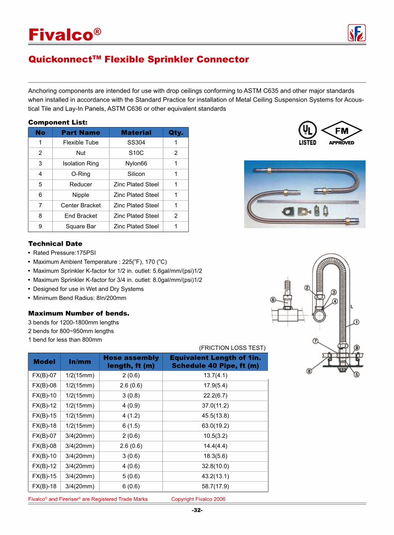
(FRICTION LOSS TEST)
Model In/mm Hose assembly length, ft (m)
Equivalent Length of 1in. Schedule 40 Pipe, ft (m)
FX(B)-07 1/2(15mm) 2 (0.6) 13.7(4.1)
FX(B)-08 1/2(15mm) 2.6 (0.6) 17.9(5.4)
FX(B)-10 1/2(15mm) 3 (0.8) 22.2(6.7)
FX(B)-12 1/2(15mm) 4 (0.9) 37.0(11.2)
FX(B)-15 1/2(15mm) 4 (1.2) 45.5(13.8)
FX(B)-18 1/2(15mm) 6 (1.5) 63.0(19.2)
FX(B)-07 3/4(20mm) 2 (0.6) 10.5(3.2)
FX(B)-08 3/4(20mm) 2.6 (0.6) 14.4(4.4)
FX(B)-10 3/4(20mm) 3 (0.6) 18.3(5.6)
FX(B)-12 3/4(20mm) 4 (0.6) 32.8(10.0)
FX(B)-15 3/4(20mm) 5 (0.6) 43.2(13.1)
FX(B)-18 3/4(20mm) 6 (0.6) 58.7(17.9)
Anchoring components are intended for use with drop ceilings conforming to ASTM C635 and other major standards when installed in accordance with the Standard Practice for installation of Metal Ceiling Suspension Systems for Acous-tical Tile and Lay-In Panels, ASTM C636 or other equivalent standards
Technical Date Rated Pressure:175PSI Maximum Ambient Temperature : 225(oF), 170 (oC) Maximum Sprinkler K-factor for 1/2 in. outlet: 5.6gal/mm/(psi)1/2 Maximum Sprinkler K-factor for 3/4 in. outlet: 8.0gal/mm/(psi)1/2 Designed for use in Wet and Dry Systems Minimum Bend Radius: 8In/200mm
Maximum Number of bends.3 bends for 1200-1800mm lengths2 bends for 800~950mm lengths1 bend for less than 800mm
Component List:No Part Name Material Qty.
1 Flexible Tube SS304 1
2 Nut S10C 2
3 Isolation Ring Nylon66 1
4 O-Ring Silicon 1
5 Reducer Zinc Plated Steel 1
6 Nipple Zinc Plated Steel 1
7 Center Bracket Zinc Plated Steel 1
8 End Bracket Zinc Plated Steel 2
9 Square Bar Zinc Plated Steel 1
QuickonnectTM Flexible Sprinkler Connector
-32-
Fivalco® and Fireriser® are Registered Trade Marks Copyright Fivalco 2006
Fivalco®
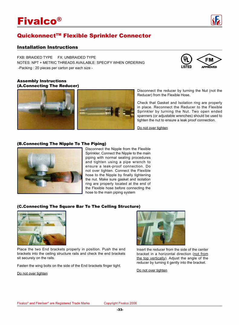
FXB: BRAIDED TYPE FX: UNBRAIDED TYPENOTES: NPT + METRIC THREADS AVAILABLE: SPECIFY WHEN ORDERING -Packing : 20 pieces per carton per each size -
(C.Connecting The Square Bar To The Celling Structure)
Assembly Instructions (A.Connecting The Reducer)
Disconnect the reducer by turning the Nut (not the Reducer) from the Flexible Hose.
Check that Gasket and Isolation ring are properly in place. Reconnect the Reducer to the Flexible Sprinkler by turning the Nut. Two open ended spanners (or adjustable wrenches) should be used to tighten the nut to ensure a leak proof connection.
Do not over tighten
(B.Connecting The Nipple To The Piping)Disconnect the Nipple from the Flexible Sprinkler. Connect the Nipple to the main piping with normal sealing procedures and tighten using a pipe wrench to ensure a leak-proof connection. Do not over tighten. Connect the Flexible hose to the Nipple by finally tightening the nut. Make sure gasket and isolation ring are properly located at the end of the Flexible hose before connecting the hose to the main piping system
Place the two End brackets properly in position. Push the end brackets into the ceiling structure rails and check the end brackets sit securely on the rails.
Fasten the wing bolts on the side of the End brackets finger tight.
Do not over tighten
Insert the reducer from the side of the center bracket in a horizontal direction (not from the top vertically). Adjust the angle of the reducer by turning it gently into the bracket.
Do not over tighten
QuickonnectTM Flexible Sprinkler Connector
Installation Instructions
-33-
Fivalco® and Fireriser® are Registered Trade Marks Copyright Fivalco 2006
Fivalco®

Material Specifications:Part Name Material EN Spec. ASTM Spec.
Body Cast Iron EN-JL1040 A126 Class B
Cover Cast Iron EN-JL1040 A126 Class B
Lever Frame Stainless Steel BS970 304S15 AISI 304
Float ball Stainless Steel BS970 304S15 AISI 304
Gasket Stainless Steel BS970 304S15 AISI 304
Cover Bolt Carbon Steel Carbon Steel A307 B
Float Arm Stainless Steel BS970 304S15 AISI 304
Orifice Button Viton Commercial Commercial
Pivot Pin Stainless Steel BS970 304S15 AISI 304
Pin Retainer Stainless Steel BS970 304S15 AISI 304
Plug Brass CuZn39Pb3 B16 C36000
Locator Stainless Steel BS970 304S15 AISI 304
Automatic Air Vent Valve
PN 16/Class 125/ 235 PSI
Dimensions (mm):Size Female Threaded1/2" 1/2" BSP or NPT
3/4" 3/4" BSP or NPT
1" 1" BSP or NPT
Working Pressure and TemperatureWorking pressure PN16/Class 125./235 PSI
Temperture from -10oC to 120oC.
Fig. 9701
-34-
Fivalco® and Fireriser® are Registered Trade Marks Copyright Fivalco 2006
Fivalco®

PRINTED IN USA
OSYSU-1, -2OUTSIDE SCREW AND YOKE VALVE
SUPERVISORY SWITCH
MKT. #8820004 - REV R MFG# 5400979 - 2/08
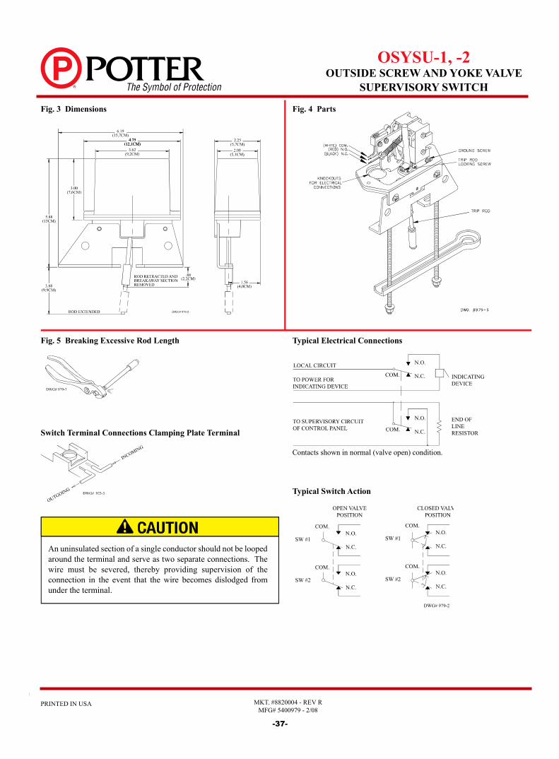
UL, ULC, and CSFM Listed, FM Approved, NYMEA Accepted, CE MarkedDimensions: 6.19"L X 2.25"W X 5.88"H 15,7cm L X 5,7cm W X 14,6cm HWeight: 2 lbs. (0,9 kg.)Enclosure: Cover - Die-Cast Finish - Red Spatter Enamel Base - Die Cast Zinc All parts have corrosion resistant fi nishes.Cover Tamper: Tamper resistant screws, Optional cover tamper kit available.Contact Ratings: OSYSU-1: One set of SPDT (Form C) OSYSU-2: Two sets of SPDT (Form C) 15.00 Amps at 125/250VAC 2.50 Amps at 30VDC resistiveEnvironmental Limitations:
• NEMA 4 and NEMA 6P Enclosure (IP67) when used with appropriate watertight conduit fi ttings.
• Indoor or Outdoor use (Not for use in hazardous locations. See bulletin no. 5400705 OSYS-U-EX for hazardous locations.)
• Temperature Range: 40°F to 140°F (40°C to 60°C)Conduit Entrances: 2 knockouts for 1/2" conduit providedService Use: Automatic Sprinkler NFPA-13 One or two family dwelling NFPA-13D Residential occupancy up to four stories NFPA-13R National Fire Alarm Code NFPA-72
General InformationThe OSYSU is used to monitor the open position of an OS&Y (outside screw and yoke) type gate valve. This device is available in two models; the OSYSU-1, containing one set of SPDT (Form C) contacts and the OSYSU-2, containing two sets of SPDT (Form C) contacts. These switches mount conveniently to most OS&Y valves ranging in size from 2" to 12" (50mm to 300mm). They will mount on some valves as small as ½" (12,5mm). The cover is held in place by two tamper resistant screws that require a special tool to remove. The tool is furnished with each device and should be left with the building owner or responsible party. Replacement or additional cover screws and hex keys are available. See Ordering Information.
Optional Cover Tamper SwitchA fi eld installable cover tamper switch is available as an option which may be used to indicate removal of the cover. See Ordering Information.
TestingThe OSYSU and its associated protective monitoring system should be inspected and tested in accordance with applicable NFPA codes and standards and/or the authority having jurisdiction (manufacturer recommends quarterly or more frequently).
Potter Electric Signal Company, LLC • 2081 Craig Road, St. Louis, MO, 63146-4161 • Phone: 800-325-3936/Canada 888-882-1833 • www.pottersignal.com
Ordering InformationModel Description Stock No.OSYSU-1 Outside Screw & Yoke-Supervisory Switch 1010106 (Single switch) OSYSU-2 Outside Screw & Yoke-Supervisory Switch 1010206 (Double switch) -- Cover Screw 5490424-- Hex Key for Cover Screws and Installation 5250062 Adjustments-- Optional Cover Tamper Switch Kit 0090131For pressure reducer type valve installation kits (if required)contact valve manufacturer.
-31--35-

MKT. #8820004 - REV R MFG# 5400979 - 2/08
PRINTED IN USA
OSYSU-1, -2OUTSIDE SCREW AND YOKE VALVE
SUPERVISORY SWITCH
Large Valve Installation1. With the valve in the FULL OPEN position, locate the OSYSU
across the valve yoke as far as possible from the valve gland, so that the trip rod lays against the non-threaded portion of the valve stem.
2. Mount the OSYSU loosely with the carriage bolts and clamp bar supplied.3. Loosen the locking screw that holds the trip rod in place and
adjust the rod length (see Fig. 4). When adjusted properly, the rod should extend past the valve screw, but not so far that it contacts the clamp bar. Tighten the locking screw to hold the trip rod in place.
Note: If trip rod length is excessive, loosen the locking screw and remove the trip rod from the trip lever. Using pliers, break off the one 1" (25mm) long notched section (see Fig. 5). Reinstall trip rod and repeat Step 3 procedure.
4. Mark the valve stem at the center of the trip rod.5. Remove the OSYSU. File a 1/8" (3,2mm) deep groove centered
on the mark of the valve stem utilizing a 3/8" (9,5mm) round, nontapered fi le. Round and smooth the edges of the groove to prevent damage to the valve packing and to allow the trip rod to move easily in and out of the groove as the valve is operated.
6. Mount the OSYSU loosely with the trip rod centered in groove.7. Final adjustment is made by loosening 2 screws (see Fig. 2) and
sliding the OSYSU on the bracket. Adjustment is correct when switches are not activated with the trip rod seated in the valve stem groove and that the switches activate within one turn when the valve is operated from the FULL OPEN towards the CLOSED position.
8. Tighten the adjustment screws and mounting hardware. Check to insure that the rod moves out of the groove easily and that the switches activate within one turn when the valve is operated from the FULL OPEN towards the CLOSED position.
Note: close the valve fully to determine that the stem threads do not activate the switch. The switch being activated by the stem threads could result in a false valve open indication.
Small Valve Installation1. Remove and discard "C" washer and roller from the trip rod.2. With the valve in the FULL OPEN position, locate the OSYSU
across the valve yoke as far as possible from the valve gland, so that the trip rod lays against the non-threaded portion of the valve stem.
3. Loosen the locking screw that holds the trip rod in place and adjust the rod length (see Fig. 4). When adjusted properly, the rod should extend past the valve screw, but not so far that it contacts the clamp bar. Tighten the locking screw to hold the trip rod in place.
Note: If trip rod length is excessive, loosen the locking screw and remove the trip rod from the trip lever. Using pliers, break off the 1" (25mm) long notched section (see Fig. 5). Reinstall trip rod and repeat Step 3 procedure.
4. Mount the OSYSU loosely with the carriage bolts and clamp bar supplied. On valves with limited clearance use J-hooks supplied instead of the carriage bolts and clamp bar to mount the OSYSU.
5. Mark the valve stem at the center of the trip rod.6. Remove the OSYSU. File a 1/8" (3,2mm) deep groove centered
on the mark on the valve stem utilizing a 3/16" (4,8mm) round, nontapered fi le. Round and smooth the edges of the groove to prevent damage to the valve packing and to allow the trip rod to move easily in and out of the groove as the valve is operated.
7. Mount the OSYSU with the trip rod centered in groove.8. Final adjustment is made by loosening 2 screws (see Fig. 1) and
sliding the OSYSU on the bracket. Adjustment is correct when switches are not activated with the trip rod seated in the valve stem groove and that the switches activate when the trip rod moves out of the groove.
9. Tighten the adjustment screws and all mounting hardware. Check to insure that the rod moves out of the groove easily and that the switches activate within one turn when the valve is operated from the FULL OPEN towards the CLOSED position.
Note: Close the valve fully to determine that the stem threads do not activate the switch. The switch being activated by the stem threads could result in a false valve open indication.
Fig. 2 Large Valve Installation 3" thru 12" (76mm thru 300mm) Sizes
Fig. 1 Small Valve Installation ½" thru 2½" (12,5mm thru 63,5mm) Sizes
These switches mount conveniently to most 2" to 12" OS&Y valves. They will mount on some valves as small as ½" (12,5mm). J-hooks may be required on valves with limited clearance.
-32--36-
PRINTED IN USA
OSYSU-1, -2OUTSIDE SCREW AND YOKE VALVE
SUPERVISORY SWITCH
MKT. #8820004 - REV R MFG# 5400979 - 2/08
Contacts shown in normal (valve open) condition.
Switch Terminal Connections Clamping Plate Terminal
Fig. 3 Dimensions Fig. 4 Parts
Fig. 5 Breaking Excessive Rod Length
An uninsulated section of a single conductor should not be looped around the terminal and serve as two separate connections. The wire must be severed, thereby providing supervision of the connection in the event that the wire becomes dislodged from under the terminal.
Typical Electrical Connections
Typical Switch Action
-33--37-

page 1 OF 2pRINTeD IN USa mFg. #5400761 - Rev Z4/10
vsr-F (FM)vane type waterFlow
alarM swItCH wItH retarD
FM approvedservice pressure: Up to 450 pSI (31 BaR)Minimum Flow rate for alarm: 10 gpm (38 Lpm)Maximum surge: 18 FpS (5,5 m/s)Contact ratings: Two sets of SpDT (Form C) 15.0 amps at 125/250vaC 2.0 amps at 30vDC ResistiveConduit entrances: Two knockouts provided for 1/2" conduitEnvironmental Specifications: • Suitable for indoor or outdoor use with factory installed gasket and
die-cast housing. • NEMA 4/IP54 Rated Enclosure - use with appropriate conduit
fitting. • Temperature Range: 40°F/120°F, 4,5°C/49°C • Non-corrosive sleeve factory installed in saddle.Caution: This device is not intended for applications in explosive
environments.sizes available: Steel Pipe schedules 10 thru 40, sizes 2" thru 8" BS 1387 pipe 50mm thru 200mm Note: For copper or plastic pipe use Model VSR-CF.service Use: Automatic Sprinkler NFPA-13 One or two family dwelling NFPA-13D Residential occupancy up to four stories NFPA-13R National Fire Alarm Code NFPA-72optional: Cover Tamper Switch Kit, Stock No. 0090018
U.S. Pat. No. 3921989Canadian Pat. No. 1009680Other Patents PendingPotter Electric, Rd., 1990
General InForMatIonThe Model VSR-F is a vane type waterflow switch for use on wet sprinkler systems. It is FM Approved for use on steel pipe; schedules 10 through 40, sizes 2" thru 8" (50mm thru 200mm).The unit may also be used as a sectional waterflow detector on large systems.The unit contains two single pole, double throw, snap action switches and an adjustable, instantly recycling pneumatic retard. The switches are actuated when a flow of 10 gallons per minute (38 Lpm) or more occurs downstream of the device. The flow condition must exist for a period of time necessary to overcome the selected retard period.enClosUre: The unit is enclosed in a general purpose, die-cast housing. The cover is held in place with two tamper resistant screws which require a special key for removal. A field installable cover tamper switch is available as an option which may be used to indicate unauthorized removal of the cover. See bulletin no. 5400775 for installation instructions of this switch.
InstallatIon: See Fig.2These devices may be mounted on horizontal or vertical pipe. On horizontal pipe they should be installed on the top side of the pipe where they will be accessible. The units should not be installed within 6" (15cm) of a fitting which changes the direction of the waterflow or within 24" (60 cm) of a valve or drain.Drain the system and drill a hole in the pipe using a circular saw in a slow speed drill. The 2" (50mm) and 2 1/2" (65mm) devices require a hole with a diameter of 1 1/4" + 1/8" - 1/16" (33mm ±2mm). All other sizes require a hole with a diameter of 2" ±1/8" (50mm ±2mm).Clean the inside pipe of all growth or other material for a distance equal to the pipe diameter on either side of the hole.Roll the vane so that it may be inserted into the hole; do not bend or crease it. Insert the vane so that the arrow on the saddle points in the direction of the waterflow. Install the saddle strap and tighten nuts alternately to an eventual 20 ft-lbs. (27 n-m) of torque (see Fig. 2). The vane must not rub the inside of the pipe or bind in any way.Specifications subject to change without notice.
Potter Electric Signal Company, LLC • St. Louis, mO • Cust. Service: 866-572-3005 • Tech. Support: 866-956-0988 • Canada 888-882-1833 • www.pottersignal.com
-34-
.
-38-

page 2 OF 2pRINTeD IN USa mFg. #5400761 - Rev Z4/10
vsr-F (FM)vane type waterFlow
alarM swItCH wItH retarD
notes: 1. The Model VSR-F has two
switches, one can be used to operate a central station, proprietary or remote signaling unit, while the other contact is used to operate a local audible or visual annunciator.
2. For supervised circuits see “Switch Terminal Connections” drawing and caution note (Fig. 1).
swItCH terMInal ConneCtIons
ClaMpInG plate terMInal
testInGThe frequency of inspection and testing for the model VSR-F and its associated protective monitoring system should be in accordance with applicable NFPA Codes and Standards and/or the authority having jurisdiction (manufacturer recommends quarterly or more frequently).If provided, the inspector’s test valve, that is usually located at the end of the most remote branch line, should always be used for test purposes. If there are no provisions for testing the operation of the flow detection device on the system, application of the VSR-F is not recommended or advisable.A minimum flow of 10 gpm (38 Lpm) is required to activate this device.IMportant notICe: Please advise the person responsible for testing of the fire protection system that this system must be tested in accordance with the testing instructions.
FIG. 1 FIG. 2
FIG. 3 typICal eleCtrICal ConneCtIons
OUTGOING
INCOMING
DWG# 923-3
FIG. 4To remove knockouts: Place screwdriver at edge of knockouts, not in the center.
2 SETS OF NORMALLY OPEN CONTACTS
CLOSE ON ALARM
THE N.C. AND N.O. MARKINGS ON THE SWITCH ARE FOR AN ALARM
CONDITION.
THE CONTACTS ARE REVERSED WHEN THE DEVICE IS IN THE
NORMAL CONDITION.
WATERFLOW ZONE ON FIRE PANEL
EOLR FROM FIRE PANEL
POSITIVE DC OR HOT AC
NEGATIVE DC OR NEUTRAL AC
DWG# 761-2
BELL
COM NO NC
COM NO NC
COM NO NC
COM NO NC
EOLR
DWG# 8810018-2
C(WHT)
N.O.(RED)
N.C.(BLK)
Cover Tamper(with cover in place)
An uninsulated section of a single conductor should not be looped around the terminal and serve as two separate connections. The wire must be severed, thereby providing supervision of the connection in the event that the wire becomes dislodged from under the terminal.
Due to the possibility of unintended discharges caused by pressure surges, trapped air, or short retard times, waterflow switches that are monitoring wet pipe sprinkler systems shall not be used as the sole initiating device to discharge AFFF, deluge, or chemical suppression systems.
-35--39-

MFG. #5401505 - REV A1/10
PRINTED IN USA PAGE 1 OF 3
PS10-2A (FM)PRESSURE SWITCH
InstallationThe Potter PS10 Series Pressure Actuated Switches are designed for the detection of a waterfl ow condition in automatic fi re sprinkler systems of particular designs such as wet pipe systems with alarm check valves, dry pipe, preaction, or deluge systems. The PS10 is also suitable to provide a low pressure supervisory signal; adjustable between 4 and 20 psi (0,27 and 1,37 BAR). 1. Apply Tefl on tape to the threaded male connection on the device. (Do not use pipe dope)2. Device should be mounted in the upright position (threaded connection down).3. Tighten the device using a wrench on the fl ats on the device.
Wiring Instructions 1. Remove the tamper resistant screws with the special key provided. 2. Run wires through an approved conduit connector and affi x the connector to the device. 3. Connect the wires to the appropriate terminal connections for the service intended. See Figures 2, 4, and 5.Testing The operation of the pressure alarm switch shall be tested upon completion of installation and periodically thereafter in accordance with the applicable NFPA codes and standards and/or the authority having jurisdiction (manufacturer recommends quarterly or more frequently).Wet System Method 1: When using PS10 and control unit with retard - connect PS10 into alarm port piping on the input side of retard chamber and electrically connect PS10 to control unit that provides a retard to compensate for surges. Insure that no unsupervised shut-off valves are present between the alarm check valve and PS10.
FM ApprovedDimensions: 4 3/4" (12,1cm)W x 2 1/4" (5,7cm)D x 4 3/8" (11,1cm)HConduit Entrance: One knockout provided for 1/2" conduit. Enclosure: Cover - Die-cast with textured red powdercoat fi nish Base - Steel/Zinc plated Pressure Connection: Nylon 1/2" NPT MaleFactory Adjustment: 5 - 7 PSI (0,34 - 0,48 BAR)Differential: 1 PSI (0,06 BAR) typicalMaximum System Pressure: 250 PSI (17,2 BAR)Switch Contacts: Two SPDT (Form C) 15.0 Amps at 125/250VAC, 2.5 Amps at 30VDCEnvironmental Specifi cations: NEMA 4/IP55 Rated Enclosure - indoor or outdoor when used with NEMA 4 conduit fi ttings. Temperature range: -40°F to 140°F (-40°C to 60°C) Tamper: Cover incorporates tamper resistant fasteners that requires a
special key for removal. One key is supplied with each device. For optional cover tamper switch kit, order Stock No. 0090134. See bulletin #5400984.
Service Use: Automatic Sprinkler NFPA-13 One or two family dwelling NFPA-13D Residential Occupancy up to four stories NFPA-13R National Fire Alarm Code NFPA-72
Potter Electric Signal Co., LLC • St. Louis, MO • Cust Service: 866-240-1870 • Tech Support:866-956-1211• Canada 888-882-1833 • www.pottersignal.com
Method 2: When using the PS10 for local bell application or with a control that does not provide a retard feature - the PS10 must be installed on the alarm outlet side of the retard chamber of the sprinkler system.Testing: Accomplished by opening the inspector's end-of-line test valve. Allow time to compensate for system or control retard. Note: Method 2 is not applicable for remote station service use, if there is an unsupervised shut-off valve between the alarm check valve and the PS10.
Wet System With Excess Pressure Connect PS10 into alarm port piping extending from alarm check valve. Retard provisions are not required. Insure that no unsupervised shut-off valves are present between the alarm check valve and the PS10. Testing: Accomplished by opening the water by-pass test valve or the inspector's end-of-line test valve. When using end-of-line test, allow time for excess pressure to bleed off.
Dry System Connect PS10 into alarm port piping that extends from the intermediate chamber of the alarm check valve. Install on the outlet side of the in-line check valve of the alarm port piping. Insure that no unsupervised shut-off valves are present between the alarm check valve and the PS10. Testing: Accomplished by opening the water by-pass test valve.Note: The above tests may also activate any other circuit closer or water motor gongs that are present on the system.
Ordering Information Model Description Stock No.PS10-2A (FM) Pressure switch with two sets 1340102 SPDT contacts Hex Key 5250062 Cover Tamper Switch Kit 0090134
-40-

MFG. #5401505 - REV A1/10
PRINTED IN USA PAGE 2 OF 3
PS10-2A (FM)PRESSURE SWITCH
Typical Sprinkler Applications
Switch Clamping Plate TerminalDimensions
OUTGOING
INCOMING
DWG# 923-3
WET SYSTEM WITH EXCESS PRESSURE
WATER MOTOR GONG
PS10
RBVSWET SYSTEM ALARM CHECK VALVE
OS & Y VALVE
WATER BY-PASS VALVE
WET SYSTEM WITHOUT EXCESS PRESSURE
WATER MOTOR GONG
WET SYSTEM ALARM CHECK VALVE
OS & Y VALVE
RBVS
WATER BY-PASS VALVE
RETARD
PS10
DRY SYSTEM ALARM CHECK VALVE
OS & Y VALVE
WATER BY-PASS VALVE
CHECK VALVE RBVS
DRY SYSTEM
PS10 WATER MOTOR GONG
DWG. #923-2AA
Fig. 2
Fig. 3
Fig. 1
An uninsulated section of a single conductor should not be looped around the terminal and serve as two separate connections. The wire must be severed, thereby providing supervision of the connection in the event that the wire becomes dislodged from under the terminal.
Closing of any shutoff valves between the alarm check valve and the PS10 will render the PS10inoperative. To comply with NFPA-72 any such valve shall be electrically supervised with asupervisory switch such as Potter Model RBVS.
NOTE: To prevent leakage, apply Tefl on tape sealant to male threads only. Do not use Pipe Dope.
Use of Pipe Joint Cement may result in obstruction of the aperture and loss of signal.
FOR LOW PRESSURE SIGNALUSED ON DRY OR PRE-ACTION SYSTEMS WITH LESS THAN 20 PSI ONLY
EOLR
COMM NO NC
TO FIRE ALARM PANEL
POSITIVE DC OR HOT AC
NEGATIVE DC OR NEUTRAL AC
TO RING A LOCAL BELL FOR WATERFLOW
COMM NO NC
BELL
FOR WATERFLOW SIGNAL
EOLR
COMM NO NC
DWG# 5924-3TO FIRE ALARM PANEL
Typical Electrical ConnectionsFig. 4
-41-
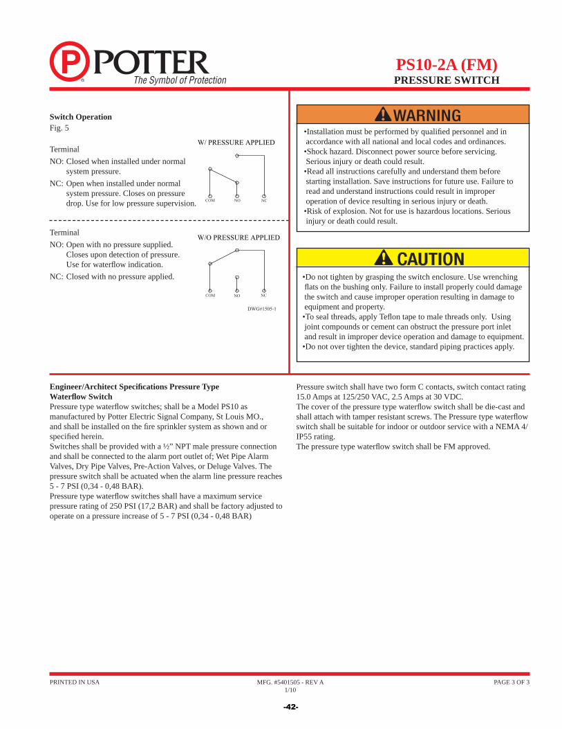
MFG. #5401505 - REV A1/10
PRINTED IN USA PAGE 3 OF 3
PS10-2A (FM)PRESSURE SWITCH
•Installation must be performed by qualifi ed personnel and in accordance with all national and local codes and ordinances. •Shock hazard. Disconnect power source before servicing. Serious injury or death could result. •Read all instructions carefully and understand them before starting installation. Save instructions for future use. Failure to read and understand instructions could result in improper operation of device resulting in serious injury or death.•Risk of explosion. Not for use is hazardous locations. Serious injury or death could result.
•Do not tighten by grasping the switch enclosure. Use wrenching fl ats on the bushing only. Failure to install properly could damage the switch and cause improper operation resulting in damage to equipment and property. •To seal threads, apply Tefl on tape to male threads only. Using joint compounds or cement can obstruct the pressure port inlet and result in improper device operation and damage to equipment. •Do not over tighten the device, standard piping practices apply.
Engineer/Architect Specifi cations Pressure Type Waterfl ow Switch Pressure type waterfl ow switches; shall be a Model PS10 as manufactured by Potter Electric Signal Company, St Louis MO., and shall be installed on the fi re sprinkler system as shown and or specifi ed herein.Switches shall be provided with a ½” NPT male pressure connection and shall be connected to the alarm port outlet of; Wet Pipe Alarm Valves, Dry Pipe Valves, Pre-Action Valves, or Deluge Valves. The pressure switch shall be actuated when the alarm line pressure reaches 5 - 7 PSI (0,34 - 0,48 BAR).Pressure type waterfl ow switches shall have a maximum service pressure rating of 250 PSI (17,2 BAR) and shall be factory adjusted to operate on a pressure increase of 5 - 7 PSI (0,34 - 0,48 BAR)
Pressure switch shall have two form C contacts, switch contact rating 15.0 Amps at 125/250 VAC, 2.5 Amps at 30 VDC.The cover of the pressure type waterfl ow switch shall be die-cast and shall attach with tamper resistant screws. The Pressure type waterfl ow switch shall be suitable for indoor or outdoor service with a NEMA 4/IP55 rating.The pressure type waterfl ow switch shall be FM approved.
W/ PRESSURE APPLIED
W/O PRESSURE APPLIED
NCNOCOM
DWG#1505-1
NCNOCOM
Switch OperationFig. 5
TerminalNO: Closed when installed under normal
system pressure.NC: Open when installed under normal
system pressure. Closes on pressure drop. Use for low pressure supervision.
TerminalNO: Open with no pressure supplied.
Closes upon detection of pressure. Use for waterfl ow indication.
NC: Closed with no pressure applied.
-42-
Fivalco Inc. Limited Warranty
Fivalco Inc, warrants each metal valve to be free from defects in material and workmanship under normal use and service for a period of one year from the date of purchase.
In the event that any defect is discovered which may be covered by this Warranty, the owner should contact Fivalco Inc, in writing or by telephone.
The owner may be instructed to return the valve at owner's expense to Fivalco Inc, or an authorized Fivalco location for inspection. In the case that inspection reveals that the valve is defective it will be replaced at Fivalco Inc.'s expense.
Replacements shall be shipped free of charge to the owners provided that the valve was installed in accordance with Fivalco Inc. Instructions and in accordance with the local authority having jurisdiction.
To the extent permitted by law this warranty specifically excludes incidental and consequential damages of every type and description resulting from any claimed defect in material or workmanship, including, but not limited to, personal injuries and property damages. To the extent permitted by law, implied warranties of merchantability and fitness for particular purposes are limited in duration.
Some jurisdictions do not allow exclusion or limitation of incidental damages and such limitations may not apply to you.
This warranty provides the owner with specific legal rights and owners may have other rights which vary by jurisdiction
Fivalco® and Fireriser® are Registered Trade Marks Copyright Fivalco 2006

WAREHOUSE SHIPPING AREA
ANAHEIM USA OFFICE/WAREHOUSE
Distributed By
Fivalco®Website: www.fivalcovalves.com