flow characteristics and velocity fields of swirling
TRANSCRIPT
Volume 26 Issue 5 Article 2
FLOW CHARACTERISTICS AND VELOCITY FIELDS OF SWIRLING DOUBLE-FLOW CHARACTERISTICS AND VELOCITY FIELDS OF SWIRLING DOUBLE-CONCENTRIC JETS AT HIGH CENTRAL JET REYNOLDS NUMBERS CONCENTRIC JETS AT HIGH CENTRAL JET REYNOLDS NUMBERS
Minh Duc Le Department of Mechanical Engineering, National Taiwan University of Scienceand Technology, Taipei, Taiwan, R.O.CFaculty of Transportation Mechanical Engineering, The University of DanangUniversity of Science and Technology, Nguyen Luong Bang, Danang, Vietnam
Ching Min Hsu Department of Mechanical Design Engineering, National Formosa University, Yunlin, Taiwan, R.O.C.
Rong Fung Huang Department of Mechanical Engineering, National Taiwan University of Science and Technology, Taipei, Taiwan, R.O.C
Follow this and additional works at: https://jmstt.ntou.edu.tw/journal
Part of the Engineering Commons
Recommended Citation Recommended Citation Le, Minh Duc; Hsu, Ching Min; and Huang, Rong Fung (2018) "FLOW CHARACTERISTICS AND VELOCITY FIELDS OF SWIRLING DOUBLE-CONCENTRIC JETS AT HIGH CENTRAL JET REYNOLDS NUMBERS," Journal of Marine Science and Technology: Vol. 26 : Iss. 5 , Article 2. DOI: 10.6119/JMST.201810_26(5).0002 Available at: https://jmstt.ntou.edu.tw/journal/vol26/iss5/2
This Research Article is brought to you for free and open access by Journal of Marine Science and Technology. It has been accepted for inclusion in Journal of Marine Science and Technology by an authorized editor of Journal of Marine Science and Technology.

FLOW CHARACTERISTICS AND VELOCITY FIELDS OF SWIRLING DOUBLE-FLOW CHARACTERISTICS AND VELOCITY FIELDS OF SWIRLING DOUBLE-CONCENTRIC JETS AT HIGH CENTRAL JET REYNOLDS NUMBERS CONCENTRIC JETS AT HIGH CENTRAL JET REYNOLDS NUMBERS
Acknowledgements Acknowledgements This research was supported by the Ministry of Science and Technology of the Taiwanese Government under contract of MOST 106-2811-E-011-006.
This research article is available in Journal of Marine Science and Technology: https://jmstt.ntou.edu.tw/journal/vol26/iss5/2
Journal of Marine Science and Technology, Vol. 26, No. 5, pp. 629-637 (2018 ) 629 DOI: 10.6119/JMST.201810_26(5).0002
FLOW CHARACTERISTICS AND VELOCITY FIELDS OF SWIRLING
DOUBLE-CONCENTRIC JETS AT HIGH CENTRAL JET REYNOLDS NUMBERS
Minh Duc Le1, 3, Ching Min Hsu2, and Rong Fung Huang1
Key words: double-concentric jets, bluff-body wake, flow visualization, PIV.
ABSTRACT
The flow characteristics and velocity fields of swirling double- concentric jets at a high central jet Reynolds number were studied. The central jet Reynolds numbers varied from 700 < Rec < 1000. The flow behaviors of the swirling double-concentric jets were observed using a laser light sheet assisted by a smoke-wire flow visualization technique. The time-averaged velocity vectors and streamlines, normalized velocity contours, fluctuation intensity contours, and vorticity contours were carried out using particle image velocimeter (PIV). Two characteristic flow modes are clas- sified: the central jet-dominated radial flow occurs at a low annular jet Reynolds number while the high-turbulence swirling wake appears at a high annular jet Reynolds number. The flow feature of the central jet-dominated radial flow presents a wide- open shear layer because of the effect of a high-speed deflected central jet. A large dual-ring vortex in the wake and two pairs of vortices in the gap between the control disk and primary disk in the high-turbulence swirling wake mode appear. The turbu- lence intensity in the high-turbulence swirling wake were signi- ficantly larger than those in the central jet-dominated radial flow.
I. INTRODUCTION
A strong swirling motion imparted on a jet significantly im- proves the mixing properties and combustion efficiencies by generating a central toroidal recirculation zone near the jet’s exit
(Rose, 1962; Chigier and Beer, 1964; Gupta et al., 1984; Park and Shin, 1993; Liang and Maxworthy, 2005; Santhosh et al., 2014). Swirl flow has widespread usage in industrial applications, such as for industrial burners, turbines, furnaces, boilers, cyclone se- parators, and combustors. In general, the reverse flow zone that contains a high turbulence fluctuation is induced when the swirl and Reynolds number are higher than about 0.6 and 18,000, re- spectively (Gupta et al., 1984).
To enhance the turbulent intensities near the jets’ exit, the ef- fects of the swirling motion and bluff body are combined in many industrial applications. By varying the blockage ratio of the central body, the recirculation zone forms near field and the flow behaviors were studied by some researchers (Escudier and Keller, 1985; Sheen et al., 1996; Huang and Tsai, 2001b; Huang and Tsai, 2004). The effects of the swirling strength and blockage ratio on the flow characteristics were carried out by Huang and Tsai (2001b, 2004). They reported the flow visualization, velo- city characteristics, and mixing properties of an annular swirl- ing jet across a circular disk that was located concentrically at the exit of the annular jet. Their results showed that when the blockage ratio is greater than 0.11, the recirculation zone in the near field can be induced, even at low annulus Reynolds and swirl numbers. The same authors later developed their previous research by studying the effects of imparting swirl motion on the annular jet of double-concentric jets with a large ratio central blockage disk (Huang and Tsai, 2001a). A jet was issued from a 5-mm hole located concentrically on the center of the block- age disk. The flow behaviors and velocity characteristics were ob- served by using the smoke-wire flow visualization method and laser Doppler velocimetry (LDV), respectively. Several flow characteristics were observed, such as single bubble, dual rings, vortex breakdown, and vortex shedding. Even though the reverse flow can be formed at the near-wake region at low swirl and annulus Reynolds numbers, the turbulence intensities were about 2%-6%. This is because the central jet was merged with the swirling jet-like flow, which was induced by the annular jet passes through the blockage disk, and then went straight for-ward downstream. Therefore, the tracer-gas concentration meas- urement showed that the mixing capability was low.
Paper submitted 07/27/17; revised 01/10/18; accepted 08/06/18. Author for correspondence: Ching Min Hsu (e-mail address: [email protected]). 1 Department of Mechanical Engineering, National Taiwan University of Science and Technology, Taipei, Taiwan, R.O.C.
2 Department of Mechanical Design Engineering, National Formosa University, Yunlin, Taiwan, R.O.C.
3 Faculty of Transportation Mechanical Engineering, The University of Danang-University of Science and Technology, Nguyen Luong Bang, Danang, Vietnam.
630 Journal of Marine Science and Technology, Vol. 26, No. 5 (2018 )
A passive-control method was developed by Huang and Yen (2003) to overcome the disadvantage of a previous study (Huang and Tsai, 2001a). A circular disk with a diameter of 14 mm was placed concentrically above the blockage disk of the swirling double-concentric jets to modulate the high-speed central jet fluid. The flow structures, turbulence properties, and mixing charac- teristics of the swirling double-concentric jets were studied. The results indicated that the turbulence properties were drastically increased when the control disk was placed at a proper distance above the blockage disk. The turbulence intensities of the con- trolled swirling double-concentric jets were about 0.7-1.1. Compared with the natural case, the turbulence intensities are extremely increased as a circular disk is installed. This is be- cause the central jet fluid deflected radially before merging with the swirling annular jet and then turned downstream to form a reverse flow in the near field. Therefore, the mixing capability was significantly improved. Huang et al. (2015) investigated the effects of the annulus Reynolds number on the flow character- istics of swirling double-concentric jets. By using smoke-wire flow visualization, hot-wire anemometer velocity measurement, and flow topology analysis, four flow modes were identified, such as annular jet-dominated wake, central jet-dominated wake, central jet-dominated radial flow, and high-turbulence swirling wake.
The current study presents the effects of annular jet Reynolds numbers on the flow fields of swirling double-concentric jets at a high central jet Reynolds number. The instantaneous flow pattern was illustrated using the smoke-wire technique and re- corded with a high-speed camera. Velocity vectors, streamlines, velocities, and turbulent intensities were resolved by PIV meas- urement.
II. EXPERIMENTAL METHODS
1. Apparatus
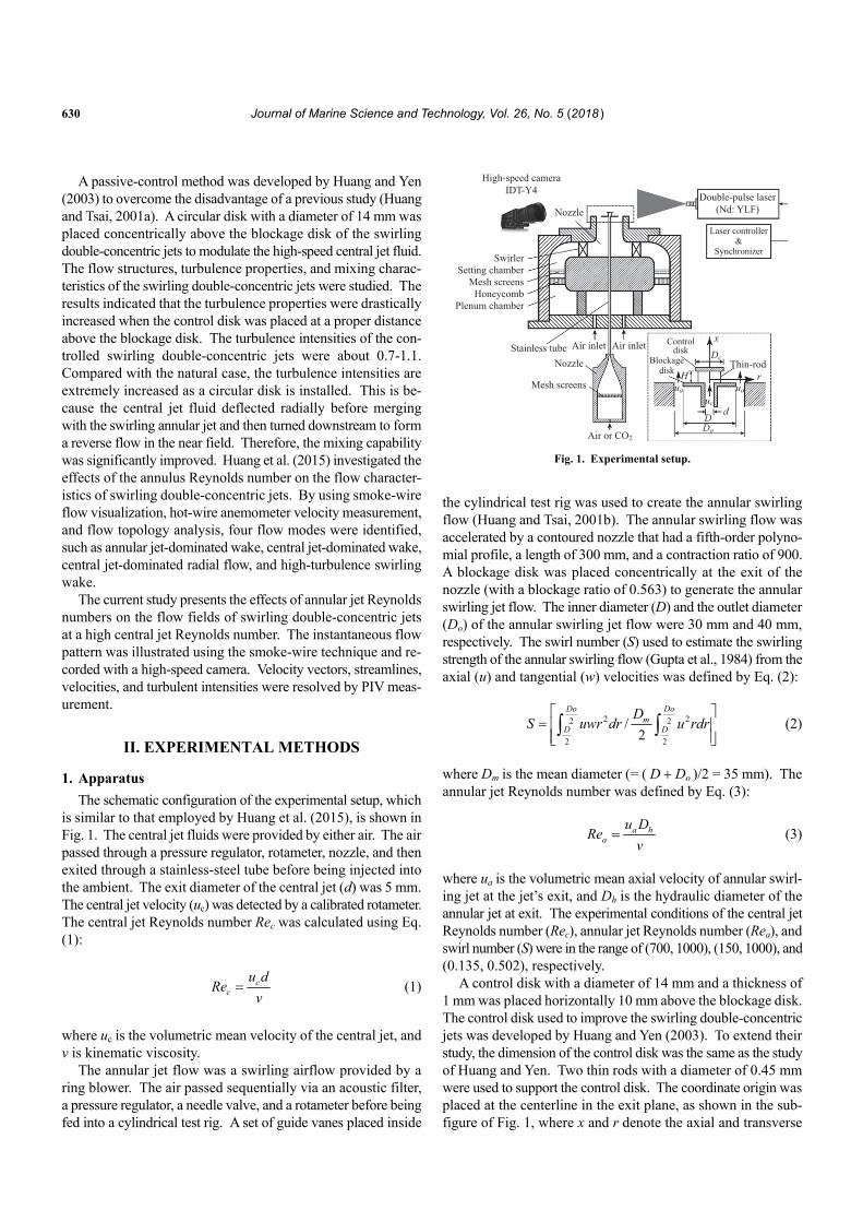
The schematic configuration of the experimental setup, which is similar to that employed by Huang et al. (2015), is shown in Fig. 1. The central jet fluids were provided by either air. The air passed through a pressure regulator, rotameter, nozzle, and then exited through a stainless-steel tube before being injected into the ambient. The exit diameter of the central jet (d) was 5 mm. The central jet velocity (uc) was detected by a calibrated rotameter. The central jet Reynolds number Rec was calculated using Eq. (1):
cc
u dRe
v (1)
where uc is the volumetric mean velocity of the central jet, and ν is kinematic viscosity.
The annular jet flow was a swirling airflow provided by a ring blower. The air passed sequentially via an acoustic filter, a pressure regulator, a needle valve, and a rotameter before being fed into a cylindrical test rig. A set of guide vanes placed inside
High-speed cameraIDT-Y4
Nozzle
SwirlerSetting chamber
Mesh screensHoneycomb
Plenum chamber
Double-pulse laser(Nd: YLF)
Laser controller&
Synchronizer
Controldisk
Blockagedisk
Air inlet
Thin-rod
D duc
ua ua
Dc
x
rH
Do
Air inletStainless tubeNozzle
Mesh screens
Air or CO2 Fig. 1. Experimental setup.
the cylindrical test rig was used to create the annular swirling flow (Huang and Tsai, 2001b). The annular swirling flow was accelerated by a contoured nozzle that had a fifth-order polyno- mial profile, a length of 300 mm, and a contraction ratio of 900. A blockage disk was placed concentrically at the exit of the nozzle (with a blockage ratio of 0.563) to generate the annular swirling jet flow. The inner diameter (D) and the outlet diameter (Do) of the annular swirling jet flow were 30 mm and 40 mm, respectively. The swirl number (S) used to estimate the swirling strength of the annular swirling flow (Gupta et al., 1984) from the axial (u) and tangential (w) velocities was defined by Eq. (2):
2 22 2
2 2
/2
Do Dom
D D
DS uwr dr u rdr
(2)
where Dm is the mean diameter (= ( D Do )/2 = 35 mm). The annular jet Reynolds number was defined by Eq. (3):
a ha
u DRe
v (3)
where ua is the volumetric mean axial velocity of annular swirl- ing jet at the jet’s exit, and Dh is the hydraulic diameter of the annular jet at exit. The experimental conditions of the central jet Reynolds number (Rec), annular jet Reynolds number (Rea), and swirl number (S) were in the range of (700, 1000), (150, 1000), and (0.135, 0.502), respectively.
A control disk with a diameter of 14 mm and a thickness of 1 mm was placed horizontally 10 mm above the blockage disk. The control disk used to improve the swirling double-concentric jets was developed by Huang and Yen (2003). To extend their study, the dimension of the control disk was the same as the study of Huang and Yen. Two thin rods with a diameter of 0.45 mm were used to support the control disk. The coordinate origin was placed at the centerline in the exit plane, as shown in the sub- figure of Fig. 1, where x and r denote the axial and transverse
M. D. Le et al.: Flow Fields Swirling Double-Concentric Jets 631
directions, respectively.
2. Flow Visualization
The flow visualization was examined with a 100-m diameter corrugated tungsten wire located on the symmetry plane across the jet’s exit at x/D = 0.03; this created smoke flow patterns. The Reynolds number based on the wire diameter was kept less than 40 to avoid vortex shedding downstream of the wire (Mueller, 1996; Zdravkovich, 1997). To create the smoke particle, a DC power supply was connected to the wire to heat up mineral oil that then was brush-coated onto the wire. The average particle diameter was 1.7 0.3 m, as measured by a Malvern 1600C Particle Analyzer. The Stokes number of the oil aerosols was around the order of 10-3 to avoid turbulent diffusion, which was much less than unity, as recommended by Flagan and Seinfeld (2013). Thus, the smoke particles were anticipated to follow the flow appropriately. A continuous laser (DPSS Laser, Shanghai Dream Lasers Technology Co., Ltd.) with a wave length of 526 nm was used to illuminate the smoke streaks. The thickness of the laser light sheet was adjusted about 0.5 mm and aligned along the smoke wire in a symmetry plane (i.e., x-r plane) so that the particles in the flow field could be illuminated. The flow pat- terns were captured using a high-speed complementary metal- oxide-semiconductor (CMOS) camera (Model MotionPro Y4, IDT Inc.) with a frame rate of 30 fps. The detailed specifications of camera and laser are given in Table 1.
3. PIV Measurement
To understand the velocity characteristics of the swirling double-concentric jets, a high-speed particle image velocimeter (PIV) was used. The PIV system consisted of a dual-head diode- pumped pulsed Neodymium doped Yttrium Lithium Fluorides (Nd: YLF) laser, an electronic synchronizer, a high-speed camera, and a commercial PIV analysis software. The laser had a wave length of 527 nm and maximum pulsing rate of 20,000 Hz. The camera used for PIV measurement was the same as the one used for the flow visualization. The camera and laser were triggered and synchronized using the electronic synchronizer. The pixel array of the CMOS camera was mapped to a physical region of 60 60 mm2 so that the spatial resolution was 92 m/pixel. The camera was operated in a double-exposure mode so that two sequential images could be captured in a brief time interval. The time interval between the two sequential laser pulses was 150 s. The frame rate was 2,300 image pairs per second. The time- averaged velocity fields were obtained from an ensemble average of 8,000 image pairs. To scatter the laser light, kerosene oil- mist particles were seeded in the central and annular jets.
The image acquisition was performed with the software proVISION-XS PIV v3.12.1, which was provided by IDI Inc. The cross-correlation between two consecutive double-exposure images was analyzed using a cross-correlation method (Keane and Adrian, 1992). To improve the resolution and accuracy of the velocity vector field, the interrogation window was set to 32 32 pixels with a 50% overlap in both directions. The overlap was used to minimize the occurrence of erroneous vectors. To
Table 1. Specification of instruments.
High-speed digital camera
Manufacturer Integrated Design Tools, Inc. (IDT).
Model Y4-S1
Maximum resolution 1,024 1,024
Maximum FPS at Maximum resolution
3,000 fps
Sensor type CMOS
Sensor size 13.9 13.9 m
Continuous laser
Manufacturer Shanghai Dream Lasers
Technology Co., Ltd.
Model SDL-532-3000-T
Output power at 25C 2,000 3,300 mW
Wave length 527 nm
Power stability after warm-up < 1%, < 3 %, < 5% (over 2/4/8 hours)
Dual head diode pumped Nd: YLF laser
Manufacturer Litron Lasers Ltd.
Model LDY300
Wave length 527 nm
Repetition rate (each cavity) 0.2 – 20,000 Hz
Output energy at 1 kHz at 527 nm per laser head per pulse
10 mJ
Pulse stability 1 %
Pulse width at 1 kHz 150 ns
Rotameter
Manufacturer Aalborg Instruments
and Controls, Inc.
Model P single flow tube meters
Accuracy 2%
reduce the velocity bias in the regions that had a large velocity gradient, the displacement of the particle in the consecutive double-exposed images was kept lower than 25% of the length of the interrogation area (Westerweel, 1997). The seeding den- sity was carefully considered to keep the number of particle- image pairs per interrogation spot no less than four; this helped avoid poor measurement reliability (Keane and Adrian, 1992). The number of vectors predetermined for the PIV analysis was set to 140 140 (19,600 vectors in total) in the symmetry plane of the flow field. To remove the outliers (the vectors outside the specified velocity range), the error-check and interpolation rou- tines were applied. The identified outliers were detected and re- placed using local-averaged neighboring values. The detected spurious vectors per instantaneous field were kept less than 2%. The specification of instruments was listed in Table 1.
4. Uncertainty Estimation
In the current study, the uncertainties of the measurements were estimated following the method proposed by Steele et al. (1993). The total uncertainty (E) of the variable parameters can be determined by combining systematic and random errors: E = [B2 (tSD)2]1/2, where B is the systematic uncertainty, SD is the standard deviation of the mean, and the degree of freedom t is 1.96 with a 95% confidence level. The systematic uncer-
632 Journal of Marine Science and Technology, Vol. 26, No. 5 (2018 )
2.0
1.5
1.0
0.5
0
2.0
-0.5 0 0.5
-0.5 0
r/D
r/D
V1
V1
V3 V4
Shear-layervortices
V2
V2
0.5
(a) Rea = 230 (S = 0.206)
(b) Rea = 683 (S = 0.480)
1.5
1.0
0.5
0
xD
xD
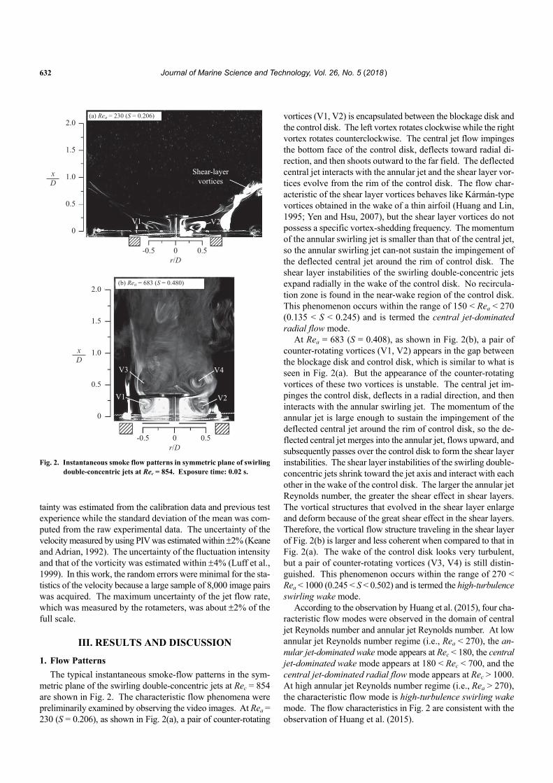
Fig. 2. Instantaneous smoke flow patterns in symmetric plane of swirling
double-concentric jets at Rec = 854. Exposure time: 0.02 s.
tainty was estimated from the calibration data and previous test experience while the standard deviation of the mean was com- puted from the raw experimental data. The uncertainty of the velocity measured by using PIV was estimated within 2% (Keane and Adrian, 1992). The uncertainty of the fluctuation intensity and that of the vorticity was estimated within 4% (Luff et al., 1999). In this work, the random errors were minimal for the sta- tistics of the velocity because a large sample of 8,000 image pairs was acquired. The maximum uncertainty of the jet flow rate, which was measured by the rotameters, was about 2% of the full scale.
III. RESULTS AND DISCUSSION
1. Flow Patterns
The typical instantaneous smoke-flow patterns in the sym- metric plane of the swirling double-concentric jets at Rec = 854 are shown in Fig. 2. The characteristic flow phenomena were preliminarily examined by observing the video images. At Rea = 230 (S = 0.206), as shown in Fig. 2(a), a pair of counter-rotating
vortices (V1, V2) is encapsulated between the blockage disk and the control disk. The left vortex rotates clockwise while the right vortex rotates counterclockwise. The central jet flow impinges the bottom face of the control disk, deflects toward radial di- rection, and then shoots outward to the far field. The deflected central jet interacts with the annular jet and the shear layer vor- tices evolve from the rim of the control disk. The flow char-acteristic of the shear layer vortices behaves like Kármán-type vortices obtained in the wake of a thin airfoil (Huang and Lin, 1995; Yen and Hsu, 2007), but the shear layer vortices do not possess a specific vortex-shedding frequency. The momentum of the annular swirling jet is smaller than that of the central jet, so the annular swirling jet can-not sustain the impingement of the deflected central jet around the rim of control disk. The shear layer instabilities of the swirling double-concentric jets expand radially in the wake of the control disk. No recircula-tion zone is found in the near-wake region of the control disk. This phenomenon occurs within the range of 150 < Rea < 270 (0.135 < S < 0.245) and is termed the central jet-dominated radial flow mode.
At Rea = 683 (S = 0.408), as shown in Fig. 2(b), a pair of counter-rotating vortices (V1, V2) appears in the gap between the blockage disk and control disk, which is similar to what is seen in Fig. 2(a). But the appearance of the counter-rotating vortices of these two vortices is unstable. The central jet im-pinges the control disk, deflects in a radial direction, and then interacts with the annular swirling jet. The momentum of the annular jet is large enough to sustain the impingement of the deflected central jet around the rim of control disk, so the de- flected central jet merges into the annular jet, flows upward, and subsequently passes over the control disk to form the shear layer instabilities. The shear layer instabilities of the swirling double- concentric jets shrink toward the jet axis and interact with each other in the wake of the control disk. The larger the annular jet Reynolds number, the greater the shear effect in shear layers. The vortical structures that evolved in the shear layer enlarge and deform because of the great shear effect in the shear layers. Therefore, the vortical flow structure traveling in the shear layer of Fig. 2(b) is larger and less coherent when compared to that in Fig. 2(a). The wake of the control disk looks very turbulent, but a pair of counter-rotating vortices (V3, V4) is still distin-guished. This phenomenon occurs within the range of 270 < Rea < 1000 (0.245 < S < 0.502) and is termed the high-turbulence swirling wake mode.
According to the observation by Huang et al. (2015), four cha- racteristic flow modes were observed in the domain of central jet Reynolds number and annular jet Reynolds number. At low annular jet Reynolds number regime (i.e., Rea < 270), the an- nular jet-dominated wake mode appears at Rec < 180, the central jet-dominated wake mode appears at 180 < Rec < 700, and the central jet-dominated radial flow mode appears at Rec > 1000. At high annular jet Reynolds number regime (i.e., Rea > 270), the characteristic flow mode is high-turbulence swirling wake mode. The flow characteristics in Fig. 2 are consistent with the observation of Huang et al. (2015).
M. D. Le et al.: Flow Fields Swirling Double-Concentric Jets 633
1.6
1.2
0.8
0.4
0
2.0
-1.6 -1.2 -0.8 -0.4 0 0.4
Bifurcation line
V2V1
V4V3
V5(a) Rea = 230 (S = 0.206)
V6
V6
V4V2
S2
S3
S1
1.0 m/s
S2S1
0.8 1.2 1.6
-1.2 -0.8 -0.4 0
r/D
r/D0.4 0.8 1.2
1.6
1.2
0.8
0.4
0V1V3
V5
xD
xD
(b) Rea = 683 (S = 0.480)
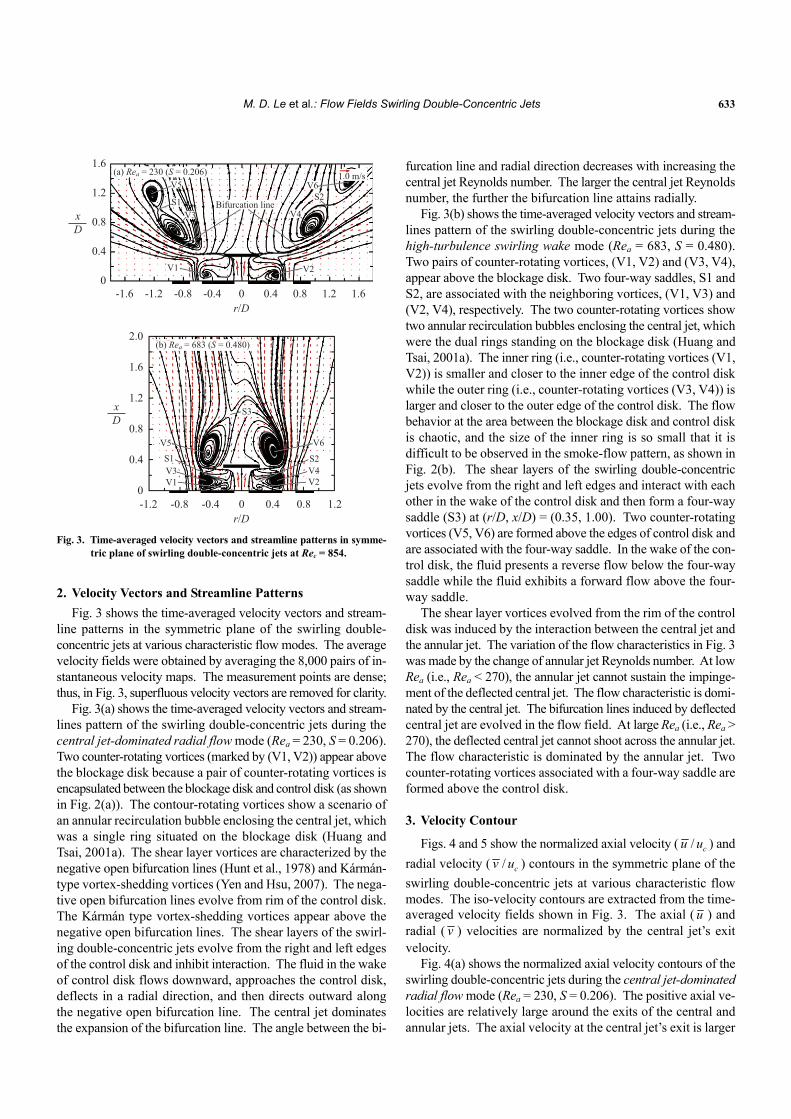
Fig. 3. Time-averaged velocity vectors and streamline patterns in symme-
tric plane of swirling double-concentric jets at Rec = 854.
2. Velocity Vectors and Streamline Patterns
Fig. 3 shows the time-averaged velocity vectors and stream- line patterns in the symmetric plane of the swirling double- concentric jets at various characteristic flow modes. The average velocity fields were obtained by averaging the 8,000 pairs of in- stantaneous velocity maps. The measurement points are dense; thus, in Fig. 3, superfluous velocity vectors are removed for clarity.
Fig. 3(a) shows the time-averaged velocity vectors and stream- lines pattern of the swirling double-concentric jets during the central jet-dominated radial flow mode (Rea = 230, S = 0.206). Two counter-rotating vortices (marked by (V1, V2)) appear above the blockage disk because a pair of counter-rotating vortices is encapsulated between the blockage disk and control disk (as shown in Fig. 2(a)). The contour-rotating vortices show a scenario of an annular recirculation bubble enclosing the central jet, which was a single ring situated on the blockage disk (Huang and Tsai, 2001a). The shear layer vortices are characterized by the negative open bifurcation lines (Hunt et al., 1978) and Kármán- type vortex-shedding vortices (Yen and Hsu, 2007). The nega- tive open bifurcation lines evolve from rim of the control disk. The Kármán type vortex-shedding vortices appear above the negative open bifurcation lines. The shear layers of the swirl- ing double-concentric jets evolve from the right and left edges of the control disk and inhibit interaction. The fluid in the wake of control disk flows downward, approaches the control disk, deflects in a radial direction, and then directs outward along the negative open bifurcation line. The central jet dominates the expansion of the bifurcation line. The angle between the bi-
furcation line and radial direction decreases with increasing the central jet Reynolds number. The larger the central jet Reynolds number, the further the bifurcation line attains radially.
Fig. 3(b) shows the time-averaged velocity vectors and stream- lines pattern of the swirling double-concentric jets during the high-turbulence swirling wake mode (Rea = 683, S = 0.480). Two pairs of counter-rotating vortices, (V1, V2) and (V3, V4), appear above the blockage disk. Two four-way saddles, S1 and S2, are associated with the neighboring vortices, (V1, V3) and (V2, V4), respectively. The two counter-rotating vortices show two annular recirculation bubbles enclosing the central jet, which were the dual rings standing on the blockage disk (Huang and Tsai, 2001a). The inner ring (i.e., counter-rotating vortices (V1, V2)) is smaller and closer to the inner edge of the control disk while the outer ring (i.e., counter-rotating vortices (V3, V4)) is larger and closer to the outer edge of the control disk. The flow behavior at the area between the blockage disk and control disk is chaotic, and the size of the inner ring is so small that it is difficult to be observed in the smoke-flow pattern, as shown in Fig. 2(b). The shear layers of the swirling double-concentric jets evolve from the right and left edges and interact with each other in the wake of the control disk and then form a four-way saddle (S3) at (r/D, x/D) = (0.35, 1.00). Two counter-rotating vortices (V5, V6) are formed above the edges of control disk and are associated with the four-way saddle. In the wake of the con- trol disk, the fluid presents a reverse flow below the four-way saddle while the fluid exhibits a forward flow above the four- way saddle.
The shear layer vortices evolved from the rim of the control disk was induced by the interaction between the central jet and the annular jet. The variation of the flow characteristics in Fig. 3 was made by the change of annular jet Reynolds number. At low Rea (i.e., Rea < 270), the annular jet cannot sustain the impinge- ment of the deflected central jet. The flow characteristic is domi- nated by the central jet. The bifurcation lines induced by deflected central jet are evolved in the flow field. At large Rea (i.e., Rea > 270), the deflected central jet cannot shoot across the annular jet. The flow characteristic is dominated by the annular jet. Two counter-rotating vortices associated with a four-way saddle are formed above the control disk.
3. Velocity Contour
Figs. 4 and 5 show the normalized axial velocity ( / cu u ) and
radial velocity ( / cv u ) contours in the symmetric plane of the
swirling double-concentric jets at various characteristic flow modes. The iso-velocity contours are extracted from the time- averaged velocity fields shown in Fig. 3. The axial ( u ) and radial ( v ) velocities are normalized by the central jet’s exit velocity.
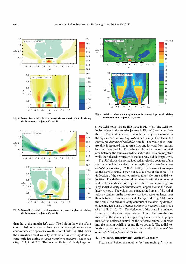
Fig. 4(a) shows the normalized axial velocity contours of the swirling double-concentric jets during the central jet-dominated radial flow mode (Rea = 230, S = 0.206). The positive axial ve- locities are relatively large around the exits of the central and annular jets. The axial velocity at the central jet’s exit is larger
634 Journal of Marine Science and Technology, Vol. 26, No. 5 (2018 )
1.6
1.2
0.8
0.4
0
2.0
-1.6 -1.2 -0.8 -0.4 0 0.4
0.92
0.75
0.55
0.45
0.40
0.30
0.08
0.02
-0.02
-0.08
-0.10
-0.12
-0.14
-0.16
-0.18
-0.20
(a) Rea = 230 (S = 0.206)
0.8 1.2 1.6
-1.2 -0.8 -0.4 0
r/D
r/D0.4 0.8 1.2
1.6
1.2
0.8
0.4
0
xD
xD
(b) Rea = 683 (S = 0.480)
v/uc
Fig. 4. Normalized axial velocities contours in symmetric plane of swirling
double-concentric jets at Rec = 854.
1.6
1.2
0.8
0.4
0
2.0
-1.6 -1.2 -0.8 -0.4 0 0.4
0.30
0.25
0.20
0.15
0.10
0.08
0.02
-0.02
-0.08
-0.10
-0.15
-0.20
-0.25
-0.30
(a) Rea = 230 (S = 0.206)
0.8 1.2 1.6
-1.2 -0.8 -0.4 0
r/D
r/D0.4 0.8 1.2
1.6
1.2
0.8
0.4
0
xD
xD
(b) Rea = 683 (S = 0.480)
v/uc
Fig. 5. Normalized radial velocities contours in symmetric plane of swirling
double-concentric jets at Rec = 854.
than that at the annular jet’s exit. The fluid in the wake of the control disk is a reverse flow, so a large negative-velocity- concentrated area appears above the control disk. Fig. 4(b) shows the normalized axial velocity contours of the swirling double- concentric jets during the high-turbulence swirling wake mode (Rea = 683, S = 0.480). The areas exhibiting relatively large po-
1.6
1.2
0.8
0.4
0
2.0
-1.6 -1.2 -0.8 -0.4 0 0.4
343026242018161412108.0
4.0
1.5
6.0
2.0
0.80
(a) Rea = 230 (S = 0.206)
0.8 1.2 1.6
-1.2 -0.8 -0.4 0
r/D
r/D0.4 0.8 1.2
1.6
1.2
0.8
0.4
0
xD
xD
(b) Rea = 683 (S = 0.480)
u′/uc (%)
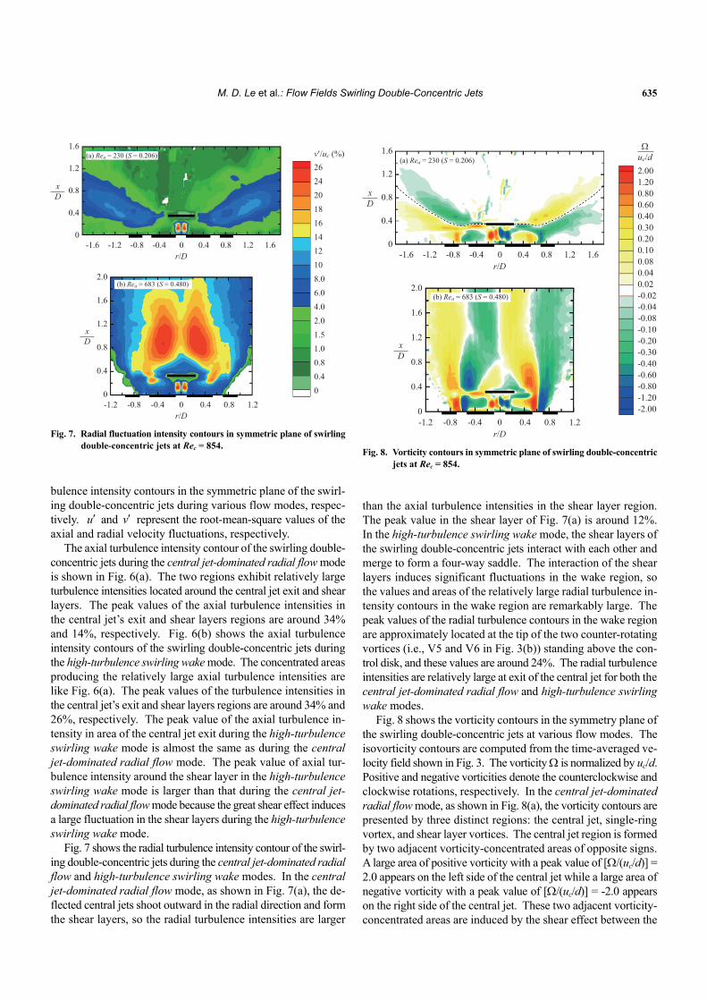
Fig. 6. Axial turbulence intensity contours in symmetric plane of swirling
double-concentric jets at Rec = 854.
sitive axial velocities are like those in Fig. 4(a). The axial ve- locity values at the annular jet area in Fig. 4(b) are larger than those in Fig. 4(a) because the annular jet Reynolds number in the high-turbulence swirling wake mode is larger than that in the central jet-dominated radial flow mode. The wake of the con- trol disk is separated into reverse-flow and forward-flow regions by a four-way saddle. The values of the velocity-concentrated area between the four-way saddle and control disk are negative while the values downstream of the four-way saddle are positive.
Fig. 5(a) shows the normalized radial velocity contours of the swirling double-concentric jets during the central jet-dominated radial flow mode (Rea = 230, S = 0.206). The central jet impinges on the control disk and then deflects in a radial direction. The deflection of the central jet induces relatively large radial ve- locities. The deflected central jet interacts with the annular jet and evolves vortices traveling in the shear layers, making it so large radial velocity-concentrated areas appear around the shear- layer vortices. The values and concentrated areas of the radial velocity contours in the shear-layer-vortices region are larger than those between the control disk and blockage disk. Fig. 5(b) shows the normalized radial velocity contours of the swirling double- concentric jets during the high-turbulence swirling wake mode (Rea = 683, S = 0.480). The deflection of the central jet induces large radial velocities under the control disk. Because the mo- mentum of the annular jet is large enough to sustain the impinge- ment of the deflected central jet, the deflected central jet merges into the annular swirling jet and flows upward. The radial ve- locity’s values are smaller when compared to the central jet- dominated radial flow mode’s values.
4. Turbulence Intensity and Vorticity Contours
Figs. 6 and 7 show the axial ( / cu u ) and radial ( / cv u ) tur-
M. D. Le et al.: Flow Fields Swirling Double-Concentric Jets 635
1.6
1.2
0.8
0.4
0
2.0
-1.6 -1.2 -0.8 -0.4 0 0.4
26242018161412108.06.04.0
1.5
0.8
2.0
1.0
0.40
(a) Rea = 230 (S = 0.206)
0.8 1.2 1.6
-1.2 -0.8 -0.4 0
r/D
r/D0.4 0.8 1.2
1.6
1.2
0.8
0.4
0
xD
xD
(b) Rea = 683 (S = 0.480)
v′/uc (%)
Fig. 7. Radial fluctuation intensity contours in symmetric plane of swirling
double-concentric jets at Rec = 854.
bulence intensity contours in the symmetric plane of the swirl- ing double-concentric jets during various flow modes, respec- tively. u and v represent the root-mean-square values of the axial and radial velocity fluctuations, respectively.
The axial turbulence intensity contour of the swirling double- concentric jets during the central jet-dominated radial flow mode is shown in Fig. 6(a). The two regions exhibit relatively large turbulence intensities located around the central jet exit and shear layers. The peak values of the axial turbulence intensities in the central jet’s exit and shear layers regions are around 34% and 14%, respectively. Fig. 6(b) shows the axial turbulence intensity contours of the swirling double-concentric jets during the high-turbulence swirling wake mode. The concentrated areas producing the relatively large axial turbulence intensities are like Fig. 6(a). The peak values of the turbulence intensities in the central jet’s exit and shear layers regions are around 34% and 26%, respectively. The peak value of the axial turbulence in- tensity in area of the central jet exit during the high-turbulence swirling wake mode is almost the same as during the central jet-dominated radial flow mode. The peak value of axial tur- bulence intensity around the shear layer in the high-turbulence swirling wake mode is larger than that during the central jet- dominated radial flow mode because the great shear effect induces a large fluctuation in the shear layers during the high-turbulence swirling wake mode.
Fig. 7 shows the radial turbulence intensity contour of the swirl- ing double-concentric jets during the central jet-dominated radial flow and high-turbulence swirling wake modes. In the central jet-dominated radial flow mode, as shown in Fig. 7(a), the de- flected central jets shoot outward in the radial direction and form the shear layers, so the radial turbulence intensities are larger
1.6
1.2
0.8
0.4
0
2.0
-1.6 -1.2 -0.8 -0.4 0 0.4
2.001.20
0.60
0.30
0.10
0.04
0.80
0.40
0.20
0.08
0.02-0.02-0.04-0.08-0.10-0.20
-0.40
-0.80
-0.30
-0.60
-1.20-2.00
(a) Rea = 230 (S = 0.206)
0.8 1.2 1.6
-1.2 -0.8 -0.4 0
r/D
r/D0.4 0.8 1.2
1.6
1.2
0.8
0.4
0
xD
xD
(b) Rea = 683 (S = 0.480)
Ωuc/d
Fig. 8. Vorticity contours in symmetric plane of swirling double-concentric
jets at Rec = 854.
than the axial turbulence intensities in the shear layer region. The peak value in the shear layer of Fig. 7(a) is around 12%. In the high-turbulence swirling wake mode, the shear layers of the swirling double-concentric jets interact with each other and merge to form a four-way saddle. The interaction of the shear layers induces significant fluctuations in the wake region, so the values and areas of the relatively large radial turbulence in- tensity contours in the wake region are remarkably large. The peak values of the radial turbulence contours in the wake region are approximately located at the tip of the two counter-rotating vortices (i.e., V5 and V6 in Fig. 3(b)) standing above the con- trol disk, and these values are around 24%. The radial turbulence intensities are relatively large at exit of the central jet for both the central jet-dominated radial flow and high-turbulence swirling wake modes.
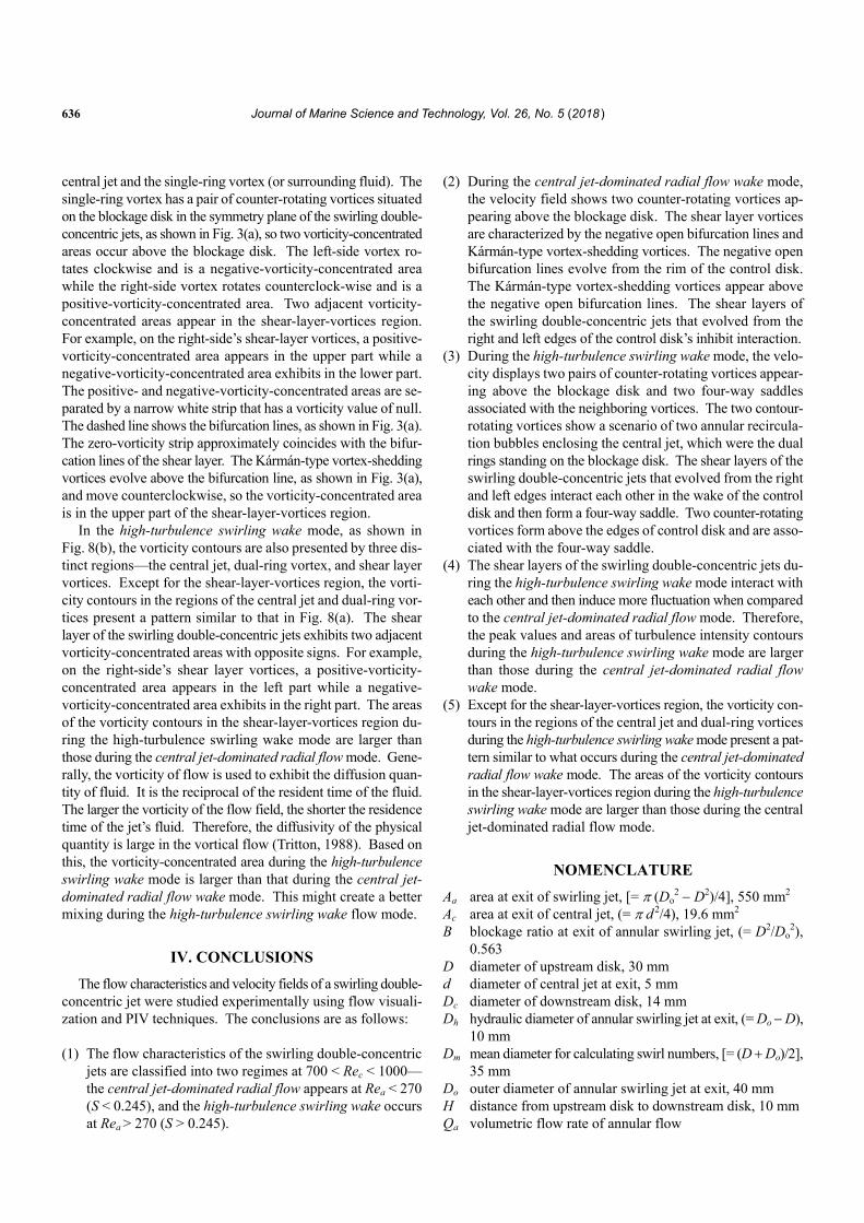
Fig. 8 shows the vorticity contours in the symmetry plane of the swirling double-concentric jets at various flow modes. The isovorticity contours are computed from the time-averaged ve- locity field shown in Fig. 3. The vorticity is normalized by uc/d. Positive and negative vorticities denote the counterclockwise and clockwise rotations, respectively. In the central jet-dominated radial flow mode, as shown in Fig. 8(a), the vorticity contours are presented by three distinct regions: the central jet, single-ring vortex, and shear layer vortices. The central jet region is formed by two adjacent vorticity-concentrated areas of opposite signs. A large area of positive vorticity with a peak value of [/(uc/d)] = 2.0 appears on the left side of the central jet while a large area of negative vorticity with a peak value of [/(uc/d)] = -2.0 appears on the right side of the central jet. These two adjacent vorticity- concentrated areas are induced by the shear effect between the
636 Journal of Marine Science and Technology, Vol. 26, No. 5 (2018 )
central jet and the single-ring vortex (or surrounding fluid). The single-ring vortex has a pair of counter-rotating vortices situated on the blockage disk in the symmetry plane of the swirling double- concentric jets, as shown in Fig. 3(a), so two vorticity-concentrated areas occur above the blockage disk. The left-side vortex ro-tates clockwise and is a negative-vorticity-concentrated area while the right-side vortex rotates counterclock-wise and is a positive-vorticity-concentrated area. Two adjacent vorticity- concentrated areas appear in the shear-layer-vortices region. For example, on the right-side’s shear-layer vortices, a positive- vorticity-concentrated area appears in the upper part while a negative-vorticity-concentrated area exhibits in the lower part. The positive- and negative-vorticity-concentrated areas are se- parated by a narrow white strip that has a vorticity value of null. The dashed line shows the bifurcation lines, as shown in Fig. 3(a). The zero-vorticity strip approximately coincides with the bifur- cation lines of the shear layer. The Kármán-type vortex-shedding vortices evolve above the bifurcation line, as shown in Fig. 3(a), and move counterclockwise, so the vorticity-concentrated area is in the upper part of the shear-layer-vortices region.
In the high-turbulence swirling wake mode, as shown in Fig. 8(b), the vorticity contours are also presented by three dis- tinct regions—the central jet, dual-ring vortex, and shear layer vortices. Except for the shear-layer-vortices region, the vorti- city contours in the regions of the central jet and dual-ring vor- tices present a pattern similar to that in Fig. 8(a). The shear layer of the swirling double-concentric jets exhibits two adjacent vorticity-concentrated areas with opposite signs. For example, on the right-side’s shear layer vortices, a positive-vorticity- concentrated area appears in the left part while a negative- vorticity-concentrated area exhibits in the right part. The areas of the vorticity contours in the shear-layer-vortices region du- ring the high-turbulence swirling wake mode are larger than those during the central jet-dominated radial flow mode. Gene- rally, the vorticity of flow is used to exhibit the diffusion quan- tity of fluid. It is the reciprocal of the resident time of the fluid. The larger the vorticity of the flow field, the shorter the residence time of the jet’s fluid. Therefore, the diffusivity of the physical quantity is large in the vortical flow (Tritton, 1988). Based on this, the vorticity-concentrated area during the high-turbulence swirling wake mode is larger than that during the central jet- dominated radial flow wake mode. This might create a better mixing during the high-turbulence swirling wake flow mode.
IV. CONCLUSIONS
The flow characteristics and velocity fields of a swirling double- concentric jet were studied experimentally using flow visuali- zation and PIV techniques. The conclusions are as follows:
(1) The flow characteristics of the swirling double-concentric
jets are classified into two regimes at 700 < Rec < 1000— the central jet-dominated radial flow appears at Rea < 270 (S < 0.245), and the high-turbulence swirling wake occurs at Rea > 270 (S > 0.245).
(2) During the central jet-dominated radial flow wake mode, the velocity field shows two counter-rotating vortices ap- pearing above the blockage disk. The shear layer vortices are characterized by the negative open bifurcation lines and Kármán-type vortex-shedding vortices. The negative open bifurcation lines evolve from the rim of the control disk. The Kármán-type vortex-shedding vortices appear above the negative open bifurcation lines. The shear layers of the swirling double-concentric jets that evolved from the right and left edges of the control disk’s inhibit interaction.
(3) During the high-turbulence swirling wake mode, the velo- city displays two pairs of counter-rotating vortices appear- ing above the blockage disk and two four-way saddles associated with the neighboring vortices. The two contour- rotating vortices show a scenario of two annular recircula- tion bubbles enclosing the central jet, which were the dual rings standing on the blockage disk. The shear layers of the swirling double-concentric jets that evolved from the right and left edges interact each other in the wake of the control disk and then form a four-way saddle. Two counter-rotating vortices form above the edges of control disk and are asso- ciated with the four-way saddle.
(4) The shear layers of the swirling double-concentric jets du- ring the high-turbulence swirling wake mode interact with each other and then induce more fluctuation when compared to the central jet-dominated radial flow mode. Therefore, the peak values and areas of turbulence intensity contours during the high-turbulence swirling wake mode are larger than those during the central jet-dominated radial flow wake mode.
(5) Except for the shear-layer-vortices region, the vorticity con- tours in the regions of the central jet and dual-ring vortices during the high-turbulence swirling wake mode present a pat- tern similar to what occurs during the central jet-dominated radial flow wake mode. The areas of the vorticity contours in the shear-layer-vortices region during the high-turbulence swirling wake mode are larger than those during the central jet-dominated radial flow mode.
NOMENCLATURE
Aa area at exit of swirling jet, [= (Do2 D2)/4], 550 mm2
Ac area at exit of central jet, (= d 2/4), 19.6 mm2 B blockage ratio at exit of annular swirling jet, (= D2/Do
2), 0.563
D diameter of upstream disk, 30 mm d diameter of central jet at exit, 5 mm Dc diameter of downstream disk, 14 mm Dh hydraulic diameter of annular swirling jet at exit, (= Do D),
10 mm Dm mean diameter for calculating swirl numbers, [= (D Do)/2],
35 mm Do outer diameter of annular swirling jet at exit, 40 mm H distance from upstream disk to downstream disk, 10 mm Qa volumetric flow rate of annular flow
M. D. Le et al.: Flow Fields Swirling Double-Concentric Jets 637
Qc volumetric flow rate of central jet Rea Reynolds number of annular flow, (= uaDh/) Rec Reynolds number of central jet, (= ucd/) r radial coordinate, originated from center of circular disk S swirl number of annular jet u instantaneous axial velocity component u time-averaged axial velocity u root-mean-square of axial velocity fluctuations ua mean axial velocity of annular swirling jet at exit, (= Qa /Aa) uc mean axial velocity of central jet at exit, (= Qc/Ac) v instantaneous radial velocity component v time-averaged radial velocity v root-mean-square of radial velocity fluctuations w azimuthal velocity component x axial coordinate, originated from center of upstream disk kinematic viscosity of air
ACKNOWLEDEGMENTS
This research was supported by the Ministry of Science and Technology of the Taiwanese Government under contract of MOST 106-2811-E-011-006.
REFERENCES
Chigier, N. A. and J. M. Beer (1964). Velocity and static-pressure distributions in swirling air jets issuing from annular and divergent nozzles. Journal of Fluids Engineering 86(4), 788-796.
Escudier, M. P. and J. Keller (1985). Recirculation in swirling flow-A manife- station of vortex breakdown. AIAA Journal 23(1), 111-116.
Flagan, R. C. and J. H. Seinfeld (1988). Fundamentals of Air Pollution Engi- neering. Prentice Hall, Englewood Cliffs, New Jersey, 295-307.
Gupta, A. K., D. G. Lilley and N. Syred (1984). Swirl Flows. Abacus Press, Tun- bridge Wells, UK.
Huang, R. F. and C. L. Lin (1995). Vortex shedding and shear-layer instability of wing at low-Reynolds numbers. AIAA Journal 33(8), 1398-1403.
Huang, R. F. and S. C. Yen (2003). Axisymmetric swirling vortical wakes mo- dulated by a control disk. AIAA Journal 41(5), 888-896.
Huang, R. F., L. M. Duc and C. M. Hsu (2015). Effects of swirling strength on flow characteristics of swirling double-concentric jets with a dual-disk flow controller. Experimental Thermal and Fluid Science 68(7), 612-624.
Huang, R. F. and F. C. Tsai (2001a). Flow field characteristics of swirling double concentric jets. Experimental Thermal and Fluid Science 25(3-4), 151-161.
Huang, R. F. and F. C. Tsai (2001b). Observations of swirling flows behind circular disks. AIAA Journal 39(6), 1106-1112.
Huang, R. F. and F. C. Tsai (2004). Flow and mixing characteristics of swirling wakes in blockage-effect regime. Journal of Wind Engineering and Indus- trial Aerodynamics 92(2), 199-214.
Hunt J. C. R., C. J. Abell, J. A. Peterka and H. Woo (1978). Kinematical studies of the flows around free or surface-mounted obstacles; applying topology to flow visualization. Journal of Fluid Mechanics 86(1), 179-200.
Keane, R. D. and R. J. Adrian (1992). Theory of cross-correlation analysis of PIV images. Applied Scientific Research 49(3), 191-215.
Liang, H. and T. Maxworthy (2005). An experimental investigation of swirling jets. Journal of Fluid Mechanics 525, 115-159.
Luff, J. D., T. Drouillard, A. M. Rompage, M. A. Linne and J. R. Hertzberg (1999). Experimental uncertainties associated with particle image velocimetry (PIV) based vorticity algorithms. Experiments in Fluids 26(1-2), 36-54.
Mueller, T. J. (1996). Flow Visualization by Direct Injection. In: Taylor & Francis, Washington DC, 364-450.
Park, S. andH. Shin (1993). Measurements of entrainment characteristics of swirl- ing jets. International Journal of Heat and Mass Transfer 36(16), 4009-4018.
Rose, W. G. (1962). A Swirling round turbulent jet: 1—Mean-flow measurements. Journal of Applied Mechanics 29(4), 615-625.
Santhosh, R., A. Miglani and S. Basu (2014). Transition in vortex breakdown modes in a coaxial isothermal unconfined swirling jet. Physics of Fluids 26(4), 043601.
Sheen, H. J., W. J. Chen and S. Y. Jeng (1996). Recirculation zones of uncon- fined and confined annular swirling jets. AIAA Journal 34(3), 572-579.
Steele, W. G., R. P. Taylor, R. E. Burrell and H. W. Coleman (1993). Use of pre- vious experience to estimate precision uncertainty of small sample experi- ments. AIAA Journal 31(10), 1891-1896.
Tritton, D. J. (1988). Physical Fluid Dynamics. Oxford University Press, Oxford, UK.
Westerweel, J. (1997). Fundamentals of digital particle image velocimetry. Measurement Science and Technology 8(12), 1379.
Yen, S. C and C. M. Hsu (2007). Flow patterns and wake structure of a swept- back wing. AIAA Journal 45(a), 228-236.
Zdravkovich, M. M. (1997). Flow around Circular Cylinders. Oxford University Press, Oxford, UK.