fluid dynamics of gas solid fluidized beds - intech -...
TRANSCRIPT

3
Fluid Dynamics of Gas – Solid Fluidized Beds
Germán González Silva1, Natalia Prieto Jiménez1 and Oscar Fabio Salazar State University of Campinas
Brazil
1. Introduction
Fluidization refers to the contact between a bed of solids and a flow of fluid. As a result, the
solid particles are transformed into a fluid-like behavior that can be used for different
purposes. The fluidized bed reactor is one of the most important technologies for gas-solid
heterogeneous operations chemical or petrochemical, considering catalytic or non catalytic
processes (Kunii and Levenspiel 1991). The most important industrial applications include
catalytic cracking, coal combustion and biomass combustion. One of the most relevant type
of fluidized bed reactor is the ascendant flow reactor, which is also known as riser. The riser
reactors consist of a tubular column in which both solid and gas flow upwards. The first
fluidized bed gas generator was developed in Germany by Fritz Winkler in the 1920s. Later
in the 1930s, the american petroleum industry started developing the fluidized bed
technology for oil feedstock catalytic cracking, becoming the primary technology for such
applications (Tavoulareas 1991).
Inside the riser reactor, solid particles have a wide range of residence time, which is a
disadvantage that reduces the overall conversion and the selectivity of the chemical reactions.
For that reason it has recently grown the interest in a new type of gas-solid circulating reactor
known as downer. In this reactor the gas and the solid flow cocurrently downward, creating
hydrodynamic features comparable to a plug flow reactor and allowing a better control over
the conversion, the selectivity and the catalyst deactivation. The concept of downer reactor
gas-solid appeared in the 1980s, with the first studies on the fluid dynamics of gas-solid
suspensions (Kim and Seader 1983) and with the first downer reactors for patents developed
by Texaco for the FCC process (Gross Benjamin and Ramage Michael P 1981; Niccum Phillip
K and Bunn Jr Dorrance P 1983). In these studies it is observed that in the downer reactor has a
uniform distribution of two-phase flow along the reactor, also observed that the contact time is
very low, achieving a 20% decrease in the amounts of coke produced during the FCC process.
Applications, differences, advantages and disadvantages to these types of fluidized bed
reactors can be found in various publications (Ancheyta 2010; Gonzalez, 2008; Yi Cheng et
al. 2008; Crowe 2005; Wen-ching Yang 2003; Grace 1997; Gidaspow 1994; Geldart 1986)
2. Fluidization regimes a nd particle classification
Fluidization occurs when a gas or liquid is forced to flow vertically through a bed of
particles at such a rate that the buoyed weight of the particles is completely supported by
the drag force imposed by the fluid.
www.intechopen.com
Advanced Fluid Dynamics
40
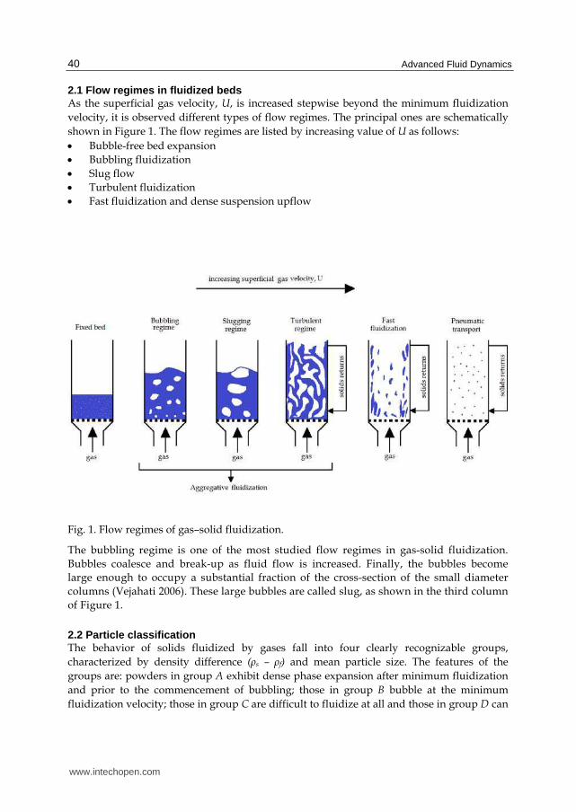
2.1 Flow regimes in fluidized beds As the superficial gas velocity, U, is increased stepwise beyond the minimum fluidization
velocity, it is observed different types of flow regimes. The principal ones are schematically
shown in Figure 1. The flow regimes are listed by increasing value of U as follows:
Bubble-free bed expansion
Bubbling fluidization
Slug flow
Turbulent fluidization
Fast fluidization and dense suspension upflow
Fig. 1. Flow regimes of gas–solid fluidization.
The bubbling regime is one of the most studied flow regimes in gas-solid fluidization.
Bubbles coalesce and break-up as fluid flow is increased. Finally, the bubbles become
large enough to occupy a substantial fraction of the cross-section of the small diameter
columns (Vejahati 2006). These large bubbles are called slug, as shown in the third column
of Figure 1.
2.2 Particle classification The behavior of solids fluidized by gases fall into four clearly recognizable groups,
characterized by density difference (ρs – ρf) and mean particle size. The features of the
groups are: powders in group A exhibit dense phase expansion after minimum fluidization
and prior to the commencement of bubbling; those in group B bubble at the minimum
fluidization velocity; those in group C are difficult to fluidize at all and those in group D can
www.intechopen.com
Fluid Dynamics of Gas – Solid Fluidized Beds
41
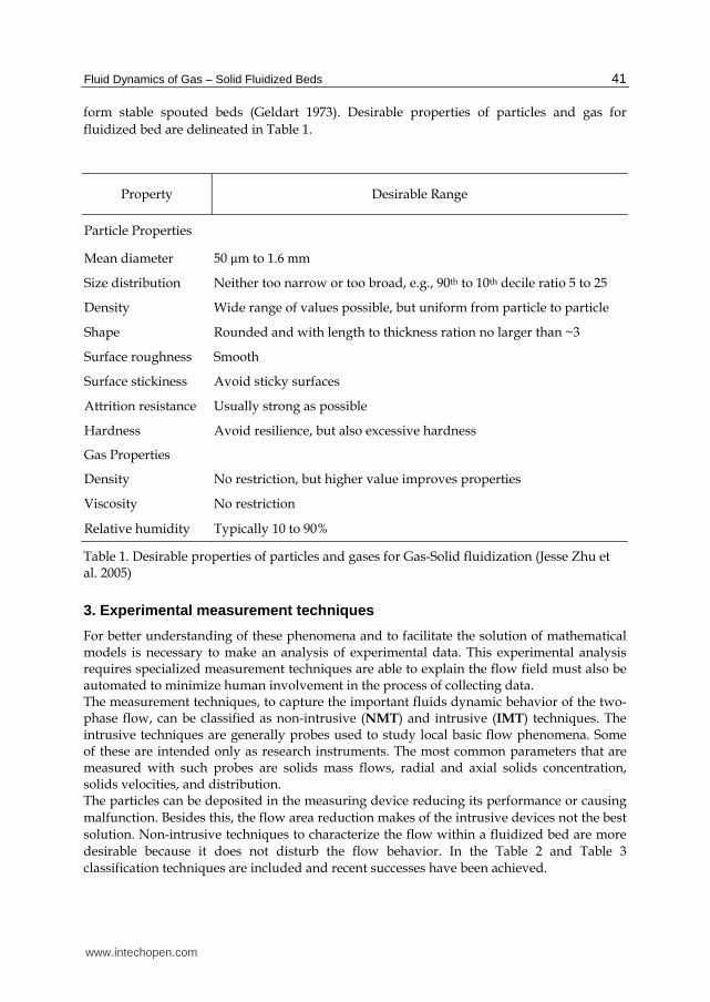
form stable spouted beds (Geldart 1973). Desirable properties of particles and gas for
fluidized bed are delineated in Table 1.
Property Desirable Range
Particle Properties
Mean diameter 50 μm to 1.6 mm
Size distribution Neither too narrow or too broad, e.g., 90th to 10th decile ratio 5 to 25
Density Wide range of values possible, but uniform from particle to particle
Shape Rounded and with length to thickness ration no larger than ~3
Surface roughness Smooth
Surface stickiness Avoid sticky surfaces
Attrition resistance Usually strong as possible
Hardness Avoid resilience, but also excessive hardness
Gas Properties
Density No restriction, but higher value improves properties
Viscosity No restriction
Relative humidity Typically 10 to 90%
Table 1. Desirable properties of particles and gases for Gas-Solid fluidization (Jesse Zhu et al. 2005)
3. Experimental measurement techniques
For better understanding of these phenomena and to facilitate the solution of mathematical models is necessary to make an analysis of experimental data. This experimental analysis requires specialized measurement techniques are able to explain the flow field must also be automated to minimize human involvement in the process of collecting data. The measurement techniques, to capture the important fluids dynamic behavior of the two-phase flow, can be classified as non-intrusive (NMT) and intrusive (IMT) techniques. The intrusive techniques are generally probes used to study local basic flow phenomena. Some of these are intended only as research instruments. The most common parameters that are measured with such probes are solids mass flows, radial and axial solids concentration, solids velocities, and distribution. The particles can be deposited in the measuring device reducing its performance or causing
malfunction. Besides this, the flow area reduction makes of the intrusive devices not the best
solution. Non-intrusive techniques to characterize the flow within a fluidized bed are more
desirable because it does not disturb the flow behavior. In the Table 2 and Table 3
classification techniques are included and recent successes have been achieved.
www.intechopen.com
Advanced Fluid Dynamics
42
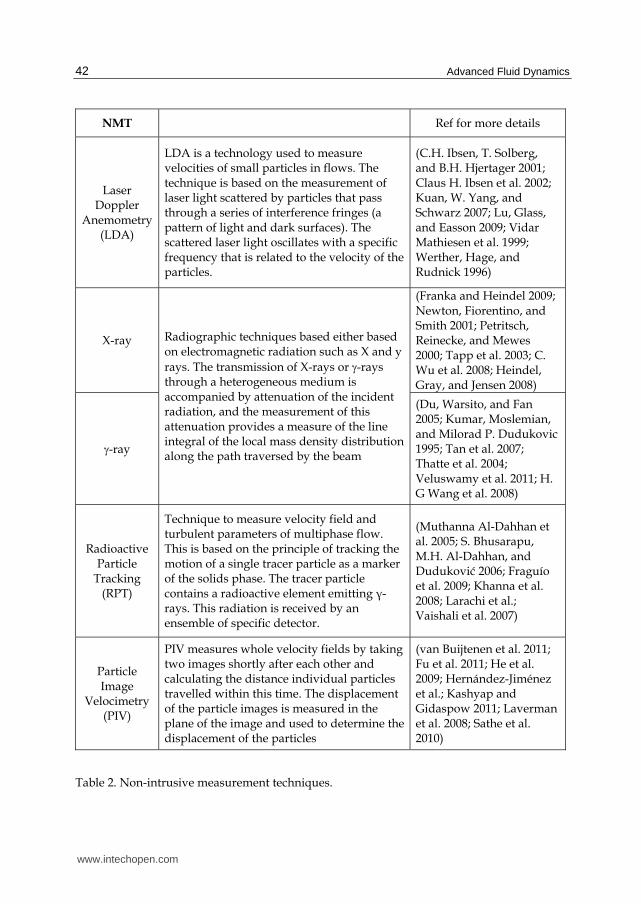
NMT Ref for more details
Laser Doppler
Anemometry (LDA)
LDA is a technology used to measure velocities of small particles in flows. The technique is based on the measurement of laser light scattered by particles that pass through a series of interference fringes (a pattern of light and dark surfaces). The scattered laser light oscillates with a specific frequency that is related to the velocity of the particles.
(C.H. Ibsen, T. Solberg, and B.H. Hjertager 2001; Claus H. Ibsen et al. 2002; Kuan, W. Yang, and Schwarz 2007; Lu, Glass, and Easson 2009; Vidar Mathiesen et al. 1999; Werther, Hage, and Rudnick 1996)
X-ray Radiographic techniques based either based on electromagnetic radiation such as X and y
rays. The transmission of X-rays or -rays through a heterogeneous medium is accompanied by attenuation of the incident radiation, and the measurement of this attenuation provides a measure of the line integral of the local mass density distribution along the path traversed by the beam
(Franka and Heindel 2009; Newton, Fiorentino, and Smith 2001; Petritsch, Reinecke, and Mewes 2000; Tapp et al. 2003; C. Wu et al. 2008; Heindel, Gray, and Jensen 2008)
-ray
(Du, Warsito, and Fan 2005; Kumar, Moslemian, and Milorad P. Dudukovic 1995; Tan et al. 2007; Thatte et al. 2004; Veluswamy et al. 2011; H. G Wang et al. 2008)
Radioactive Particle
Tracking (RPT)
Technique to measure velocity field and turbulent parameters of multiphase flow. This is based on the principle of tracking the motion of a single tracer particle as a marker of the solids phase. The tracer particle contains a radioactive element emitting γ-rays. This radiation is received by an ensemble of specific detector.
(Muthanna Al-Dahhan et al. 2005; S. Bhusarapu, M.H. Al-Dahhan, and Duduković 2006; Fraguío et al. 2009; Khanna et al. 2008; Larachi et al.; Vaishali et al. 2007)
Particle Image
Velocimetry (PIV)
PIV measures whole velocity fields by taking two images shortly after each other and calculating the distance individual particles travelled within this time. The displacement of the particle images is measured in the plane of the image and used to determine the displacement of the particles
(van Buijtenen et al. 2011; Fu et al. 2011; He et al. 2009; Hernández-Jiménez et al.; Kashyap and Gidaspow 2011; Laverman et al. 2008; Sathe et al. 2010)
Table 2. Non-intrusive measurement techniques.
www.intechopen.com

Fluid Dynamics of Gas – Solid Fluidized Beds
43
IMT
References
Pitot Tube Mechanical method based on determination of momentum by means of differential pressure measurements
(Al-Hasan and Al-Qodah 2007; Bader, R., Findlay, J. and Knowlton, TM 1988; R.-C. Wang and Han 1999)
Fiber Optic Probe
This technique is commonly used as effective tools to measure the local porosity in fluidized beds.
(Fischer, Peglow, and Tsotsas 2011; Link et al. 2009; Meggitt 2010; Zhengyang Wang et al. 2009; Ye, Qi, and J. Zhu 2009; Zhou et al. 2010; Haiyan Zhu et al. 2008)
Capacitance Probe
This technique is used to measure the local dielectric constant of the gas-solid suspension, which is linked to the local volume fraction of solids
(A. Collin, K.-E. Wirth, and Stroeder 2009; Anne Collin, Karl‐Ernst Wirth, and Ströder 2008; Demori et al. 2010; Guo and Werther 2008; Vogt et al. 2005; Wiesendorf 2000)
Table 3. Intrusive measurement techniques.
4. Computational fluid dynamics (CFD)
Computational Fluid Dynamics (CFD) is a technique which uses conservation principles and rigorous equations of fluid flow (Navier-Stokes) along with specialized turbulence
models (k-, k-, SST among others). These models are more accurate and fundamentally more acceptable than empirical ones. The empirical models are approximations that assemble different phenomena to remove a number of unknown parameters. For this reason, these models are not reliable and therefore should not be generalized. The CFD models can be divided into two groups: the Eulerian-Eulerian model in which the gas and solid phases are considered as two interpenetrating continuum flows; and the Eulerian-Lagrangian model that consider the gas as a fluid phase and the solids as discrete phase. The Eulerian-Lagrangian model calculates the trajectory of each individual particle using Newton’s second law. The interaction between particles can be described by the potential energy or the dynamic of collisions. This method has the advantage of knowing exactly the particle trajectory and the system variables. However, this requires high computational effort, higher yet when gas and solid velocity fields are coupled.
4.1 Governing equations Governing equations for Eulerian-Eulerian model are here presented in tensor notation.
4.1.1 Continuity equations The gas and solid continuity equations are represented by:
0g g g g gvt
(1)
www.intechopen.com
Advanced Fluid Dynamics
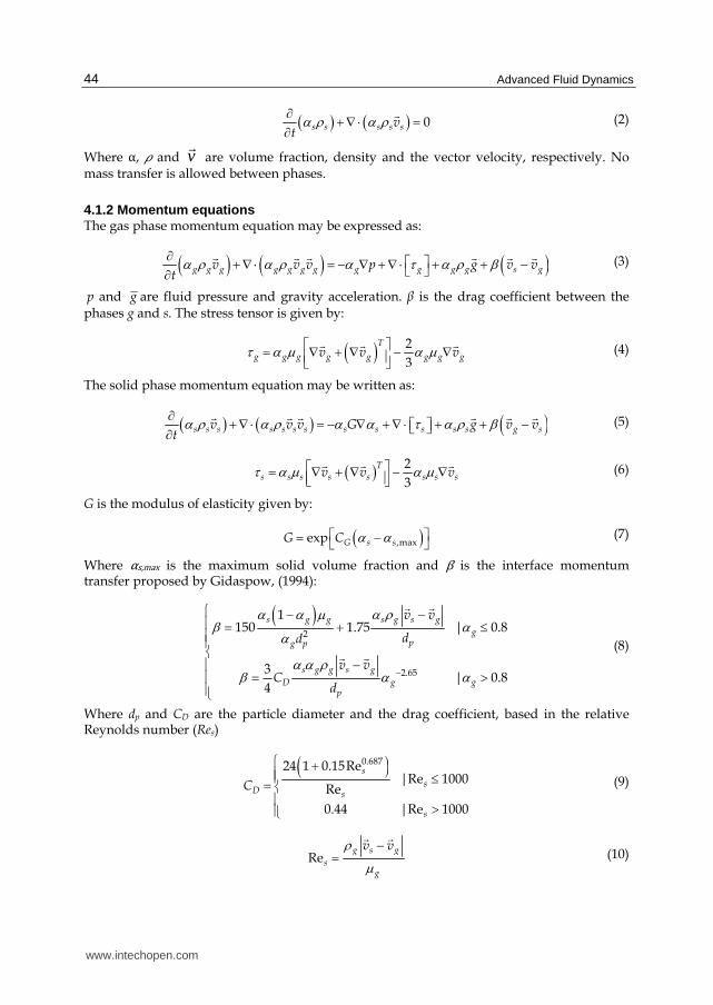
44
0s s s s svt
(2)
Where ゎ, 貢 and v
are volume fraction, density and the vector velocity, respectively. No mass transfer is allowed between phases.
4.1.2 Momentum equations The gas phase momentum equation may be expressed as:
g g g g g g g g g g g s gv v v p g v vt
(3)
p and g are fluid pressure and gravity acceleration. β is the drag coefficient between the phases g and s. The stress tensor is given by:
2
3
T
g g g g g g g gv v v (4)
The solid phase momentum equation may be written as:
s s s s s s s s s s s s g sv v v G g v vt (5)
2
3
Ts s s s s s s sv v v
(6)
G is the modulus of elasticity given by:
,maxexp G s sG C (7)
Where ゎs,max is the maximum solid volume fraction and が is the interface momentum transfer proposed by Gidaspow, (1994):
2
2.65
1150 1.75 | 0.8
3| 0.8
4
s g g s g s g
gpg p
s g g s g
D g gp
v v
dd
v vC
d
(8)
Where dp and CD are the particle diameter and the drag coefficient, based in the relative Reynolds number (Res)
0.68724 1 0.15Re
|Re 1000Re
0.44 |Re 1000
s
sD s
s
C
(9)
Reg s g
sg
v v
(10)
www.intechopen.com
Fluid Dynamics of Gas – Solid Fluidized Beds
45
4.1.3 Energy equation The gas and solid energy equations can be written as:
rg g g g g g g g g g s g g g r
r
CH v H T T T H
t t (11)
s s s s s s s s s s g sH v H T T Tt
(12)
Where H = Specific enthalpy T = Temperature γ = Interface heat transfer coefficient: / pNu d
┣ = Thermal conductivity
4.2 Turbulence models Turbulence is that state of fluid motion which is characterized by random and chaotic three-
dimensional vorticity. When turbulence is present, it usually dominates all other flow
phenomena and results in increased energy dissipation, mixing, heat transfer, and drag. The
physical turbulence models provide the solution the closure problem in solving Navier –
Stokes equations. While there are ten unknown variables (mean pressure, three velocity
components, and six Reynolds stress components), there are only four equations (mass
balance equation and three velocity component momentum balance equations). This
disparity in number between unknowns and equations make a direct solution of any
turbulent flow problem impossible in this formulation. The fundamental problem of
turbulence modeling is to relate the six Reynolds stress components to the mean flow
quantities and their gradients in some physically plausible manner.
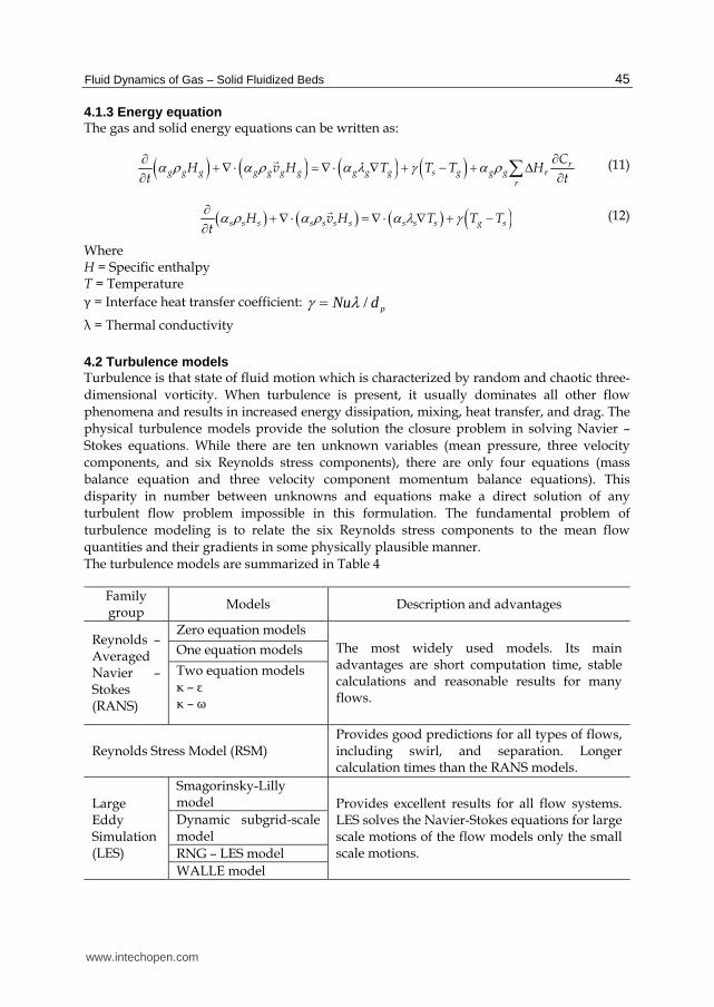
The turbulence models are summarized in Table 4
Family group
Models Description and advantages
Reynolds – Averaged Navier – Stokes (RANS)
Zero equation models
The most widely used models. Its main advantages are short computation time, stable calculations and reasonable results for many flows.
One equation models
Two equation models ┢ – ε ┢ – ω
Reynolds Stress Model (RSM) Provides good predictions for all types of flows, including swirl, and separation. Longer calculation times than the RANS models.
Large Eddy Simulation (LES)
Smagorinsky-Lilly model Provides excellent results for all flow systems.
LES solves the Navier-Stokes equations for large scale motions of the flow models only the small scale motions.
Dynamic subgrid-scale model
RNG – LES model
WALLE model
www.intechopen.com
Advanced Fluid Dynamics
46
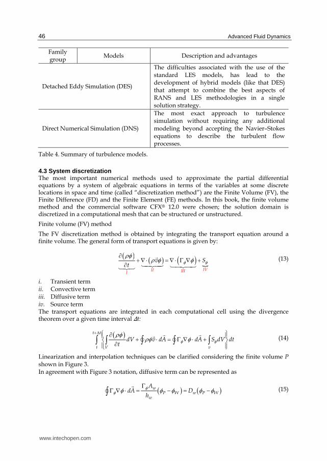
Family group
Models Description and advantages
Detached Eddy Simulation (DES)
The difficulties associated with the use of the standard LES models, has lead to the development of hybrid models (like that DES) that attempt to combine the best aspects of RANS and LES methodologies in a single solution strategy.
Direct Numerical Simulation (DNS)
The most exact approach to turbulence simulation without requiring any additional modeling beyond accepting the Navier–Stokes equations to describe the turbulent flow processes.
Table 4. Summary of turbulence models.
4.3 System discretization The most important numerical methods used to approximate the partial differential equations by a system of algebraic equations in terms of the variables at some discrete locations in space and time (called “discretization method”) are the Finite Volume (FV), the Finite Difference (FD) and the Finite Element (FE) methods. In this book, the finite volume method and the commercial software CFX® 12.0 were chosen; the solution domain is discretized in a computational mesh that can be structured or unstructured.
Finite volume (FV) method
The FV discretization method is obtained by integrating the transport equation around a finite volume. The general form of transport equations is given by:
IVII IIII
v St
(13)
i. Transient term ii. Convective term iii. Diffusive term iv. Source term The transport equations are integrated in each computational cell using the divergence theorem over a given time interval ∆t:
t t
t V v
dV v dA dA S dV dtt
(14)
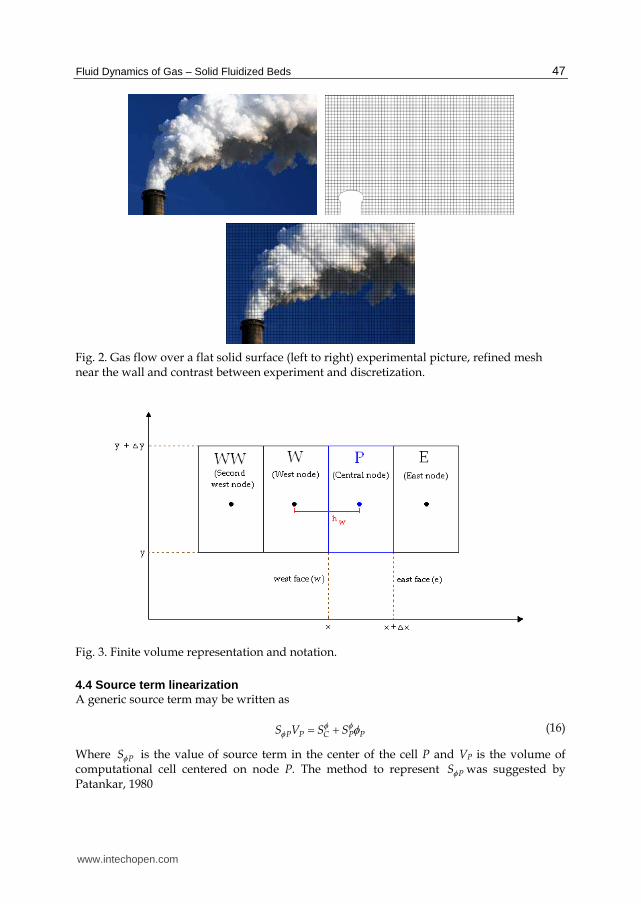
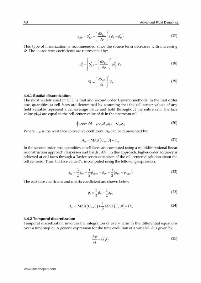
Linearization and interpolation techniques can be clarified considering the finite volume P shown in Figure 3. In agreement with Figure 3 notation, diffusive term can be represented as
wP W w P W
w
AdA D
h
(15)
www.intechopen.com
Fluid Dynamics of Gas – Solid Fluidized Beds
47
Fig. 2. Gas flow over a flat solid surface (left to right) experimental picture, refined mesh near the wall and contrast between experiment and discretization.
Fig. 3. Finite volume representation and notation.
4.4 Source term linearization A generic source term may be written as
P P P PCS V S S (16)
Where PS is the value of source term in the center of the cell P and VP is the volume of computational cell centered on node P. The method to represent PS was suggested by Patankar, 1980
www.intechopen.com
Advanced Fluid Dynamics
48
*
* *PP P P P
dSS S
d
(17)
This type of linearization is recommended since the source term decreases with increasing Φ. The source term coefficients are represented by:
*
* *PP P PC
dSS S V
d
(18)
*
PP P
dSS V
d
(19)
4.4.1 Spatial discretization The most widely used in CFD is first and second order Upwind methods. In the first order one, quantities at cell faces are determined by assuming that the cell-center values of any field variable represent a cell-average value and hold throughout the entire cell. The face value (Φw) are equal to the cell-center value of Φ in the upstream cell.
w w W w Wv dA v A C
(20)
Where, Cw is the west face convective coefficient. Aw can be represented by:
,0w w wA MAX C D (21)
In the second order one, quantities at cell faces are computed using a multidimensional linear reconstruction approach (Jespersen and Barth 1989). In this approach, higher-order accuracy is achieved at cell faces through a Taylor series expansion of the cell-centered solution about the cell centroid. Thus, the face value Φw is computed using the following expression:
3 1 1
2 2 2w W WW W W WW (22)
The east face coefficient and matrix coefficient are shown below
3 1
2 2e P W (23)
1,0 ,0
2w w e wA MAX C MAX C D (24)
4.4.2 Temporal discretization Temporal discretization involves the integration of every term in the differential equations
over a time step ∆t. A generic expression for the time evolution of a variable Φ is given by
Ft
(25)
www.intechopen.com
Fluid Dynamics of Gas – Solid Fluidized Beds
49
Where the function F incorporates any spatial discretization. The first-order accurate
temporal discretization is given by
1n n
Ft
(26)
And the second-order discretization is given by
1 13 4
2
n n n
Ft
(27)
5. Case studies
In order to give a better introduction with regards to the simulation of fluidized beds, in this chapter there are presented three case studies that were carried out by using a CFD software package. The case studies were carried out using simulations in dynamic state. These simulations
were set up taking into account the average value of the Courant number, which is recommended to be near 1. Besides this, it was used a constant step time, in this way was possible to have numerical stability during the execution of each of the simulations.
5.1 Cases 1 and 2 Lab scale riser reactor (Samuelsberg and B. H. Hjertager 1996; V Mathiesen 2000). Riser height, 1 m; riser diameter, 0.032 m. Experimental data and LES - Smagorinsky simulations were compared for three velocities with initial particle bed, 5cm.
5.1.1 Mesh parameters and boundary conditions Control volumes number: 100.000
∆x = 2 mm
Matrix determinant > 0.5 and minimum angle > 50° The boundary conditions for both cases are shown in Table 5 and Table 6. In addition, tests were made with a 500.000 control volume mesh with same block distribution (the description of volume distribution in the meshes, are presented in Table 7).
Obtaining similar results with the 100.000 control volume mesh. Both meshes are shown in Figure 4.
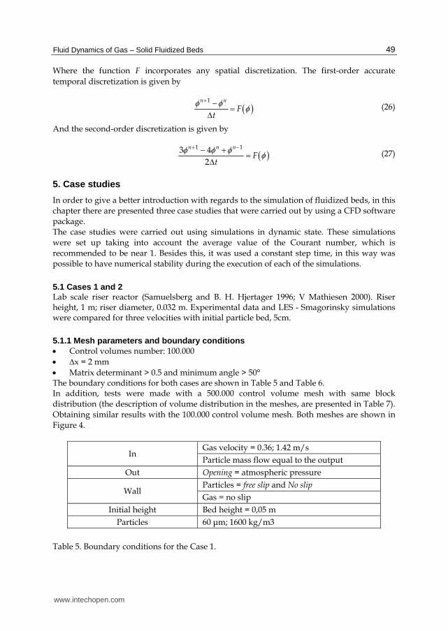
In Gas velocity = 0.36; 1.42 m/s
Particle mass flow equal to the output
Out Opening = atmospheric pressure
Wall Particles = free slip and No slip
Gas = no slip
Initial height Bed height = 0,05 m
Particles 60 ┤m; 1600 kg/m3
Table 5. Boundary conditions for the Case 1.
www.intechopen.com
Advanced Fluid Dynamics
50
In Gas velocity = 1 m/s
Particle mass flow equal to the output
Out Opening = atmospheric pressure
Wall Particles = No slip
Gas = No slip
Initial height Bed height = 0.05 m
Particles 120 ┤m, 2400 kg.m-3
Table 6. Boundary conditions for the Case 2.
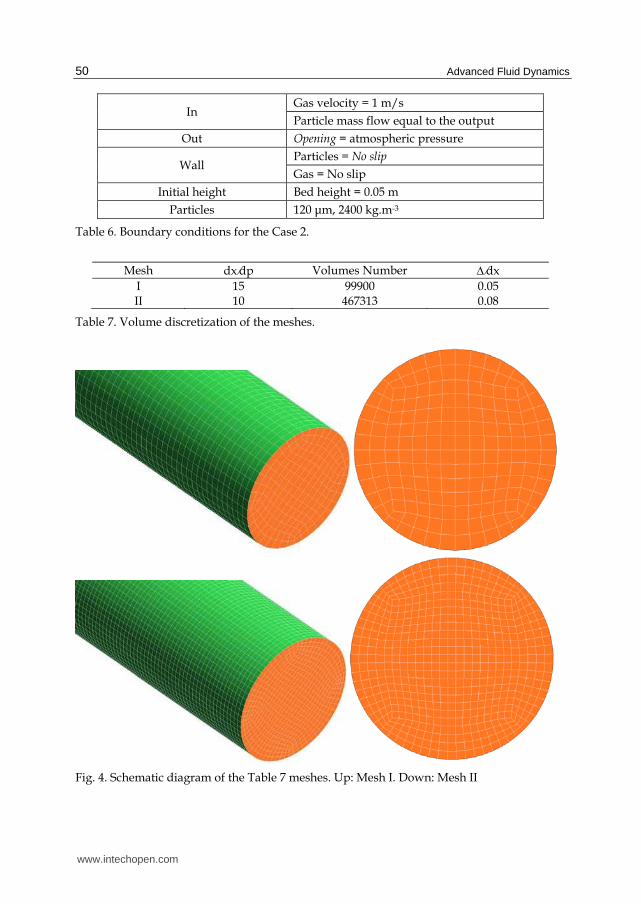
Mesh dxdp Volumes Number dx
I 15 99900 0.05 II 10 467313 0.08
Table 7. Volume discretization of the meshes.
Fig. 4. Schematic diagram of the Table 7 meshes. Up: Mesh I. Down: Mesh II
www.intechopen.com
Fluid Dynamics of Gas – Solid Fluidized Beds
51
Numeric calculations performed (Vreman, Geurts, and Kuerten 1997; Chow and Moin 2003) showed that the required values to obtain an accurate numerical solution, it is necessary to
use a ratio dx 0.25 for the second order spatial scheme, and a ratio dx < 0.5 for the sixth order scheme.
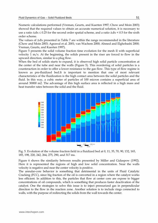
The values of dx presented in Table 7 are within the range recommended in the literature (Chow and Moin 2003; Agrawal et al. 2001; van Wachem 2000; Ahmed and Elghobashi 2000; Vreman, Geurts, and Kuerten 1997). Figure 5 presents the solid volume fraction time evolution for the mesh II with superficial velocity 1 m/s. At the beginning, the solids present in the riser are forced to flow in the upward direction, similar to a plug flow. When the bed of solids starts to expand, it is observed high solid particle concentration at the center of the tube and near the walls (Figure 5). This reordering of solid particles is a counteraction in order to offer a lower resistance to the gas flow. This type of flow regime is known as pre-fluidized bed.It is important to mention that one of most relevant characteristics of the fluidization is the high contact area between the solid particles and the fluid. In this way, a cubic meter of particles of 100 micron contains a superficial area of around 30000 m2. The advantage of this high surface area is reflected in a high mass and heat transfer rates between the solid and the fluid.
Fig. 5. Evolution of the volume fraction field in a fluidized bed at 0, 11, 35, 70, 90, 132, 165, 185, 198, 220, 242, 264, 275, 290, and 317 ms.
Figure 6 shows the similarity between results presented by Miller and Gidaspow (1992). Here it is represented the regions of high and low solid concentration. Near the walls velocity is negative and near the center velocity is positive. The annular-core behavior is something that detrimental in the units of Fluid Catalytic Cracking (FCC), since big fraction of the oil is converted in a region where the catalyst works less efficient. In addition to this, the particles that flow at center core are expose to bigger concentrations of oil compounds, which is something that produces faster deactivation of the catalyst. One the strategies to solve this issue is to inject pressurized gas in perpendicular direction to the flow in the reaction zone. Another solution is to include rings connected to walls, with the purpose of redirecting the solids from the wall towards the center.
www.intechopen.com
Advanced Fluid Dynamics
52
‐0.5
0
0.5
1
1.5
2
2.5
‐1 ‐0.8 ‐0.6 ‐0.4 ‐0.2 0 0.2 0.4 0.6 0.8 1
Solids Velocity , m/s
r/R
H= 0.32 m
Fig. 6. Comparison of solid phase velocity profile presented by Miller and Gidaspow (1992) with the CFD simulations (-▲-) and experimental data performed by Samuelsberg and B. H. Hjertager (1996) (●).
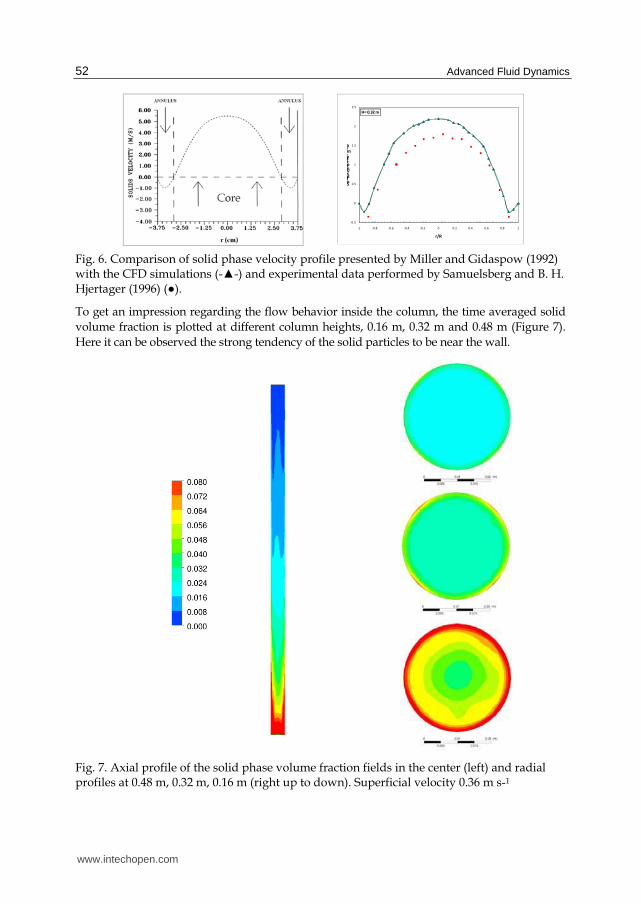
To get an impression regarding the flow behavior inside the column, the time averaged solid volume fraction is plotted at different column heights, 0.16 m, 0.32 m and 0.48 m (Figure 7).
Here it can be observed the strong tendency of the solid particles to be near the wall.
Fig. 7. Axial profile of the solid phase volume fraction fields in the center (left) and radial profiles at 0.48 m, 0.32 m, 0.16 m (right up to down). Superficial velocity 0.36 m s-1
www.intechopen.com
Fluid Dynamics of Gas – Solid Fluidized Beds
53
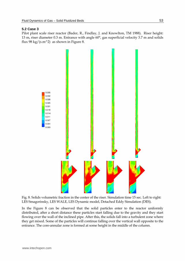
5.2 Case 3 Pilot plant scale riser reactor (Bader, R., Findlay, J. and Knowlton, TM 1988). Riser height: 13 m, riser diameter 0.3 m. Entrance with angle 60°, gas superficial velocity 3.7 m and solids flux 98 kg/(s.m^2) as shown in Figure 8.
Fig. 8. Solids volumetric fraction in the center of the riser. Simulation time 15 sec. Left to right: LES Smagorinsky, LES WALE, LES Dynamic model, Detached Eddy Simulation (DES).
In the Figure 8 can be observed that the solid particles enter to the reactor uniformly distributed, after a short distance these particles start falling due to the gravity and they start flowing over the wall of the inclined pipe. After this, the solids fall into a turbulent zone where they get mixed. Some of the particles will continue falling over the vertical wall opposite to the entrance. The core-annular zone is formed at some height in the middle of the column.
www.intechopen.com
Advanced Fluid Dynamics
54
6. Conclusions
Computational fluids dynamics is a very powerful tool understanding the behavior of multi phase in engineering applications. Large eddy simulation (LES) turbulence method provides a very detailed description of two phase flow, which makes it suitable for simulation models that are validated with experimental data. By applying the LES method, it is possible to characterize different regions of a fluidized bed (core-annulus). LES can be considered as a valuable method for development and validation of closure models that include additional phenomena like heat exchange, mass transfer and chemical reactions. It is important to constantly monitor the simulation, using parameters such as the Courant number, creating a function that calculates the maximum and average number of the control volume courant. The average value is recommended that is near or less than unity. Finally, it is important to comment that success in the validation of experimental data depends on the appropriate choice of the experimental technique used to measure variables.
7. Acknowledgements
The author G. Gonzalez is grateful to PETROBRAS and the National Council for Scientific and Technological Development (CNPq) for the financial support to this research.
8. References
Agrawal, Kapil, Peter N Loezos, Madhava Syamlal, and Sankaran Sundaresan. 2001. “The role of meso-scale structures in rapid gas solid flows.” Journal of Fluid Mechanics 445 (01) (October): 151-185.
Ahmed, A. M., and S. Elghobashi. 2000. “On the mechanisms of modifying the structure of turbulent homogeneous shear flows by dispersed particles.” Physics of Fluids 12 (11): 2906. doi:10.1063/1.1308509.
Al-Dahhan, Muthanna, Milorad P. Dudukovic, Satish Bhusarapu, Timothy J. O’hern, Steven Trujillo, and Michael R. Prairie. 2005. Flow Mapping in a Gas-Solid Riser via Computer Automated Radioactive Particle Tracking (CARPT).
http://www.osti.gov/energycitations/servlets/purl/881590-Kfq80v/. Al-Hasan, M., and Z. Al-Qodah. 2007. Characteristics of gas-solid flow in vertical tube. In
9th International Symposium on Fluid Control Measurement and Visualization 2007, FLUCOME 2007, 1:264-271.
Ancheyta, Jorge. 2010. Modeling and simulation of catalytic reactors for petroleum refining. Oxford: Wiley-Blackwell.
Bader, R., Findlay, J. and Knowlton, TM. 1988. Gas/ Solid Flow Patterns in a 30.5-cm-Diameter Circulating Fluidized Bed. In Circulating fluidized bed technology II: proceedings of the Second International Conference on Circulating Fluidized Beds, Compiègne, France, 14-18 March 1988, by Prabir Basu and Jean François Large. Pergamon Press.
Bhusarapu, S., M.H. Al-Dahhan, and M.P. Duduković. 2006. “Solids flow mapping in a gas-solid riser: Mean holdup and velocity fields.” Powder Technology 163 (1-2): 98-123.
van Buijtenen, Maureen S., Willem-Jan van Dijk, Niels G. Deen, J.A.M. Kuipers, T. Leadbeater, and D.J. Parker. 2011. “Numerical and experimental study on multiple-
www.intechopen.com
Fluid Dynamics of Gas – Solid Fluidized Beds
55
spout fluidized beds.” Chemical Engineering Science 66 (11) (June 1): 2368-2376. doi:16/j.ces.2011.02.055.
Collin, A., K.-E. Wirth, and M. Stroeder. 2009. “Characterization of an annular fluidized bed.” Powder Technology 190 (1-2): 31-35.
Collin, Anne, Karl‐Ernst Wirth, and Michael Ströder. 2008. “Experimental characterization of the flow pattern in an annular fluidized bed.” The Canadian Journal of Chemical Engineering 86 (3) (June 1): 536-542. doi:10.1002/cjce.20056.
Crowe, Clayton T. 2005. Multiphase Flow Handbook. 1st ed. CRC Press, September 19. Cheng, Yi, Changning Wu, Jingxu Zhu, Fei Wei, and Yong Jin. 2008. “Downer reactor: From
fundamental study to industrial application.” Powder Technology 183 (3) (April 21): 364-384. doi:16/j.powtec.2008.01.022.
Chow, Fotini Katopodes, and Parviz Moin. 2003. “A further study of numerical errors in large-eddy simulations.” Journal of Computational Physics 184 (2) (January 20): 366-380. doi:doi: 10.1016/S0021-9991(02)00020-7.
Demori, M., V. Ferrari, D. Strazza, and P. Poesio. 2010. “A capacitive sensor system for the analysis of two-phase flows of oil and conductive water.” Sensors and Actuators, A: Physical 163 (1): 172-179.
Du, Bing, W. Warsito, and Liang-Shih Fan. 2005. “ECT Studies of Gas−Solid Fluidized Beds of Different Diameters.” Industrial & Engineering Chemistry Research 44 (14) (July 1): 5020-5030. doi:10.1021/ie049025n.
Fischer, C., M. Peglow, and E. Tsotsas. 2011. “Restoration of particle size distributions from fiber-optical in-line measurements in fluidized bed processes.” Chemical Engineering Science 66 (12) (June 15): 2842-2852. doi:16/j.ces.2011.03.054.
Fraguío, M.S., M.C. Cassanello, S. Degaleesan, and M. Dudukovic. 2009. “Flow regime diagnosis in bubble columns via pressure fluctuations and computer-assisted radioactive particle tracking measurements.” Industrial and Engineering Chemistry Research 48 (3): 1072-1080.
Franka, Nathan P., and Theodore J. Heindel. 2009. “Local time-averaged gas holdup in a fluidized bed with side air injection using X-ray computed tomography.” Powder Technology 193 (1) (July 10): 69-78. doi:16/j.powtec.2009.02.008.
Fu, Y., T. Wang, J.-C. Chen, C.-G. Gu, and F. Xu. 2011. “Experimental investigation of jet influence on gas-solid the two-phase crossflow in a confined domain.” Shiyan Liuti Lixue/Journal of Experiments in Fluid Mechanics 25 (1): 48-53+64.
Geldart, D. 1986. Gas fluidization technology. Chichester, New York: Wiley. Geldart, D. 1973. “Types of gas fluidization.” Powder Technology 7 (5) (May): 285-292.
doi:16/0032-5910(73)80037-3. Gidaspow, Dimitri. 1994. Multiphase flow and fluidization: continuum and kinetic theory
descriptions. Boston: Academic Press. Gonzalez,, S.G. 2008. Modeling and simulation of cocurrent downflow reactor (Downer).
Master’s thesis, Campinas, Brazil: State University of Campinas. Grace, John. 1997. Circulating fluidized beds. 1st ed. London;: Blackie Academic &
Professional. Gross Benjamin, and Ramage Michael P. 1981. FCC Reactor With A Downflow Reactor
Riser. April 14. Guo, Q., and J. Werther. 2008. “Influence of a gas maldistribution of distributor design on
the hydrodynamics of a CFB riser.” Chemical Engineering and Processing: Process Intensification 47 (2): 237-244.
www.intechopen.com
Advanced Fluid Dynamics
56
He, Y., N. G. Deen, M. van Sint Annaland, and J. A. M. Kuipers. 2009. “Gas−Solid Turbulent Flow in a Circulating Fluidized Bed Riser: Experimental and Numerical Study of Monodisperse Particle Systems.” Industrial & Engineering Chemistry Research 48 (17): 8091-8097. doi:10.1021/ie8015285.
Heindel, Theodore J., Joseph N. Gray, and Terrence C. Jensen. 2008. “An X-ray system for visualizing fluid flows.” Flow Measurement and Instrumentation 19 (2) (April): 67-78. doi:16/j.flowmeasinst.2007.09.003.
Hernández-Jiménez, F., S. Sánchez-Delgado, A. Gómez-García, and A. Acosta-Iborra. “Comparison between two-fluid model simulations and particle image analysis & velocimetry (PIV) results for a two-dimensional gas-solid fluidized bed.” Chemical Engineering Science In Press, Corrected Proof. doi:16/j.ces.2011.04.026. http://www.sciencedirect.com/science/article/pii/S0009250911002685.
Ibsen, C.H., T. Solberg, and B.H. Hjertager. 2001. “Evaluation of a three-dimensional numerical model of a scaled circulating fluidized bed.” Industrial and Engineering Chemistry Research 40 (23): 5081-5086.
Ibsen, Claus H., Tron Solberg, Bjørn H. Hjertager, and Filip Johnsson. 2002. “Laser Doppler anemometry measurements in a circulating fluidized bed of metal particles.” Experimental Thermal and Fluid Science 26 (6-7): 851-859. doi:16/S0894-1777(02)00196-6.
Jespersen, Dennis C, and Timothy J Barth. 1989. “The design and application of upwind schemes on unstructured meshes.” AIAA paper 89 (89-0366): 1–12.
Kashyap, Mayank, and Dimitri Gidaspow. 2011. “Measurements of Dispersion Coefficients for FCC Particles in a Free Board.” Industrial & Engineering Chemistry Research 50 (12) (June 15): 7549-7565. doi:10.1021/ie1012079.
Khanna, Pankaj, Todd Pugsley, Helen Tanfara, and Hubert Dumont. 2008. “Radioactive particle tracking in a lab‐scale conical fluidized bed dryer containing pharmaceutical granule.” The Canadian Journal of Chemical Engineering 86 (3) (June 1): 563-570. doi:10.1002/cjce.20073.
Kim, J. M, and J. D Seader. 1983. “Pressure drop for cocurrent downflow of gas‐solids suspensions.” AIChE Journal 29 (3) (May 1): 353-360. doi:10.1002/aic.690290302.
Kuan, B., W. Yang, and M.P. Schwarz. 2007. “Dilute gas-solid two-phase flows in a curved 90° duct bend: CFD simulation with experimental validation.” Chemical Engineering Science 62 (7): 2068-2088.
Kumar, Sailesh B., Davood Moslemian, and Milorad P. Dudukovic. 1995. “A [gamma]-ray tomographic scanner for imaging voidage distribution in two-phase flow systems.” Flow Measurement and Instrumentation 6 (1): 61-73. doi:16/0955-5986(95)93459-8.
Kunii, D, and O Levenspiel. 1991. Fluidization engineering. 2nd ed. Boston Mass.: Butterworth-Heinemann.
Larachi, Faical, M H Al-Dahhan, M P Duduković, and Shantanu Roy. “Optimal design of radioactive particle tracking experiments for flow mapping in opaque multiphase reactors.” Applied radiation and isotopes including data instrumentation and methods for use in agriculture industry and medicine 56 (3): 485-503.
Laverman, Jan Albert, Ivo Roghair, Martin van Sint Annaland, and Hans Kuipers. 2008. “Investigation into the hydrodynamics of gas–solid fluidized beds using particle image velocimetry coupled with digital image analysis.” The Canadian Journal of Chemical Engineering 86 (3) (June 1): 523-535. doi:10.1002/cjce.20054.
www.intechopen.com
Fluid Dynamics of Gas – Solid Fluidized Beds
57
Link, J.M., W. Godlieb, P. Tripp, N.G. Deen, S. Heinrich, J.A.M. Kuipers, M. Schönherr, and M. Peglow. 2009. “Comparison of fibre optical measurements and discrete element simulations for the study of granulation in a spout fluidized bed.” Powder Technology 189 (2): 202-217. doi:16/j.powtec.2008.04.017.
Lu, Y., D.H. Glass, and W.J. Easson. 2009. “An investigation of particle behavior in gas-solid horizontal pipe flow by an extended LDA technique.” Fuel 88 (12): 2520-2531.
Mathiesen, V. 2000. “An experimental and computational study of multiphase flow behavior in a circulating fluidized bed.” International Journal of Multiphase Flow 26 (3) (March): 387-419. doi:10.1016/S0301-9322(99)00027-0.
Mathiesen, Vidar, Tron Solberg, Hamid Arastoopour, and Bjørn H Hjertager. 1999. “Experimental and computational study of multiphase gas/particle flow in a CFB riser.” AIChE Journal 45 (12) (December 1): 2503-2518. doi:10.1002/aic.690451206.
Meggitt, B.T. 2010. Fiber Optics in Sensor Instrumentation. In Instrumentation Reference Book (Fourth Edition), 191-216. Boston: Butterworth-Heinemann.
Miller, Aubrey, and Dimitri Gidaspow. 1992. “Dense, vertical gas‐solid flow in a pipe.” AIChE Journal 38 (11) (November 1): 1801-1815. doi:10.1002/aic.690381111.
Newton, D., M. Fiorentino, and G.B. Smith. 2001. “The application of X-ray imaging to the developments of fluidized bed processes.” Powder Technology 120 (1-2): 70-75.
Niccum Phillip K, and Bunn Jr Dorrance P. 1983. Catalytic Cracking System. March 23. Patankar, Suhas. 1980. Numerical heat transfer and fluid flow. Washington; New York:
Hemisphere Pub. Corp; McGraw-Hill. Petritsch, Georg, Nicolas Reinecke, and Dieter Mewes. 2000. Visualization Techniques in
Process Engineering. In Ullmann’s Encyclopedia of Industrial Chemistry. Wiley-VCH Verlag GmbH & Co. KGaA.
Samuelsberg, A., and B. H. Hjertager. 1996. “An experimental and numerical study of flow patterns in a circulating fluidized bed reactor.” International Journal of Multiphase Flow 22 (3) (June): 575-591. doi:16/0301-9322(95)00080-1.
Sathe, M.J., I.H. Thaker, T.E. Strand, and J.B. Joshi. 2010. “Advanced PIV/LIF and shadowgraphy system to visualize flow structure in two-phase bubbly flows.” Chemical Engineering Science 65 (8): 2431-2442.
Tan, H.-T., G.-G. Dong, Y.-D. Wei, and M.-X. Shi. 2007. “Application of γ-ray attenuation technology in measurement of solid concentration of gas-solid two-phase flow in a FCC riser.” Guocheng Gongcheng Xuebao/The Chinese Journal of Process Engineering 7 (5): 895-899.
Tapp, H.S., A.J. Peyton, E.K. Kemsley, and R.H. Wilson. 2003. “Chemical engineering applications of electrical process tomography.” Sensors and Actuators, B: Chemical 92 (1-2): 17-24.
Tavoulareas, E S. 1991. “Fluidized-Bed Combustion Technology.” Annual Review of Energy and the Environment 16 (1) (November): 25-57. doi:10.1146/annurev.eg. 16.110191.000325.
Thatte, A. R., R. S. Ghadge, A. W. Patwardhan, J. B. Joshi, and G. Singh. 2004. “Local Gas Holdup Measurement in Sparged and Aerated Tanks by γ-Ray Attenuation Technique.” Industrial & Engineering Chemistry Research 43 (17): 5389-5399. doi:10.1021/ie049816p.
Vaishali, S., S. Roy, S. Bhusarapu, M.H. Al-Dahhan, and M.P. Dudukovic. 2007. “Numerical simulation of gas-solid dynamics in a circulating fluidized-bed riser with geldart group B particles.” Industrial and Engineering Chemistry Research 46 (25): 8620-8628.
www.intechopen.com
Advanced Fluid Dynamics
58
Vejahati, F. 2006. CFD simulation of gas-solid bubbling fluidized bed. Master’s thesis, University of Regina.
Veluswamy, Ganesh K., Rajesh K. Upadhyay, Ranjeet P. Utikar, Geoffrey M. Evans, Moses O. Tade, Michael E. Glenny, Shantanu Roy, and Vishnu K. Pareek. 2011. “Hydrodynamics of a Fluid Catalytic Cracking Stripper Using γ-ray Densitometry.” Industrial & Engineering Chemistry Research 50 (10) (May 18): 5933-5941. doi:10.1021/ie1021877.
Vogt, C., R. Schreiber, G. Brunner, and J. Werther. 2005. “Fluid dynamics of the supercritical fluidized bed.” Powder Technology 158 (1-3): 102-114.
Vreman, Bert, Bernard Geurts, and Hans Kuerten. 1997. “Large-eddy simulation of the turbulent mixing layer.” Journal of Fluid Mechanics 339 (May): 357-390. doi:10.1017/S0022112097005429.
van Wachem. 2000. Derivation, Implementation, and Validation of Computer Simulation Models for Gas-Solid Fluidized Beds. Ph.D. Thesis, Delft University of Technology.
Wang, H. G, W. Q Yang, P. Senior, R. S Raghavan, and S. R Duncan. 2008. “Investigation of batch fluidized‐bed drying by mathematical modeling, CFD simulation and ECT measurement.” AIChE Journal 54 (2) (February 1): 427-444. doi:10.1002/aic.11406.
Wang, R.-C., and Y.-C. Han. 1999. “Momentum dissipation of jet dispersion in a gas-solid fluidized bed.” Journal of the Chinese Institute of Chemical Engineers 30 (3): 263-271.
Wang, Zhengyang, Shaozeng Sun, Hao Chen, Qigang Deng, Guangbo Zhao, and Shaohua Wu. 2009. “Experimental investigation on flow asymmetry in solid entrance region of a square circulating fluidized bed.” Particuology 7 (6): 483-490. doi:16/j.partic.2009.07.004.
Werther, J., B. Hage, and C. Rudnick. 1996. “A comparison of laser Doppler and single-fibre reflection probes for the measurement of the velocity of solids in a gas-solid circulating fluidized bed.” Chemical Engineering and Processing: Process Intensification 35 (5) (October): 381-391. doi:16/0255-2701(96)80018-3.
Wiesendorf, Volker. 2000. The Capacitance Probe: A Tool for Flow Investigations in Gas-solids Fluidization Systems. Shaker Verlag GmbH, Germany, September 8.
Wu, C., Y. Cheng, M. Liu, and Y. Jin. 2008. “Measurement of axisymmetric two-phase flows by an improved X-ray-computed tomography technique.” Industrial and Engineering Chemistry Research 47 (6): 2063-2074.
Yang, Wen-ching. 2003. Handbook of fluidization and fluid-particle systems. New York: Marcel Dekker.
Ye, S., X. Qi, and J. Zhu. 2009. “Direct Measurements of Instantaneous Solid Flux in a CFB Riser using a Novel Multifunctional Optical Fiber Probe.” Chemical Engineering & Technology 32 (4) (April 1): 580-589. doi:10.1002/ceat.200800361.
Zhou, Hao, Guiyuan Mo, Jiapei Zhao, Jianzhong Li, and Kefa Cen. 2010. “Experimental Investigations on the Performance of a Coal Pipe Splitter for a 1000 MW Utility Boiler: Influence of the Vertical Pipe Length.” Energy & Fuels 24 (9): 4893-4903. doi:10.1021/ef1007209.
Zhu, Haiyan, Jesse Zhu, Guozheng Li, and Fengyun Li. 2008. “Detailed measurements of flow structure inside a dense gas-solids fluidized bed.” Powder Technology 180 (3): 339-349. doi:16/j.powtec.2007.02.043.
Zhu, Jesse, Bo Leckner, Yi Cheng, and John Grace. 2005. Fluidized Beds. In Multiphase Flow Handbook, ed. Clayton Crowe, 20052445:5-1-5-93. CRC Press, September.
www.intechopen.com
Advanced Fluid DynamicsEdited by Prof. Hyoung Woo Oh
ISBN 978-953-51-0270-0Hard cover, 272 pagesPublisher InTechPublished online 09, March, 2012Published in print edition March, 2012
InTech EuropeUniversity Campus STeP Ri Slavka Krautzeka 83/A 51000 Rijeka, Croatia Phone: +385 (51) 770 447 Fax: +385 (51) 686 166www.intechopen.com
InTech ChinaUnit 405, Office Block, Hotel Equatorial Shanghai No.65, Yan An Road (West), Shanghai, 200040, China
Phone: +86-21-62489820 Fax: +86-21-62489821
This book provides a broad range of topics on fluid dynamics for advanced scientists and professionalresearchers. The text helps readers develop their own skills to analyze fluid dynamics phenomenaencountered in professional engineering by reviewing diverse informative chapters herein.
How to referenceIn order to correctly reference this scholarly work, feel free to copy and paste the following:
Germán González Silva, Natalia Prieto Jiménez and Oscar Fabio Salazar (2012). Fluid Dynamics of Gas -Solid Fluidized Beds, Advanced Fluid Dynamics, Prof. Hyoung Woo Oh (Ed.), ISBN: 978-953-51-0270-0,InTech, Available from: http://www.intechopen.com/books/advanced-fluid-dynamics/fluid-dynamics-of-gas-solid-fluidized-beds

© 2012 The Author(s). Licensee IntechOpen. This is an open access articledistributed under the terms of the Creative Commons Attribution 3.0License, which permits unrestricted use, distribution, and reproduction inany medium, provided the original work is properly cited.