fluid power division - eatonpub/@eaton/@aero... · aerospace marine defense fluid power division...
TRANSCRIPT

Aerospace Marine Defense
Fluid Power DivisionInline Motors
_ _ ------------ -i -1
t __ J
Decitv SmayE-0A
A Descriptive Summary of VickersFixed and Variable Displacement InlinePiston Motors and their Applications inAerospace, Marine and DefenseHydraulic Systems
----- ----------------------- -----------
-------------- -------------------------------------- - - - - - - - - - -

3 Inline Design Motor
4 Identification Code
5 Introduction
6 Qualities That MakeVickers Inline Motors
Better
7 Major Components
8 Basic Operation Power StrokeExhaust StrokeDeveloped Torque
11 Component Features Drive Shaft and Bearings Retainer RingCylinder Block SpacerPiston and Shoes Valve BlockAngle Block HousingYoke External SealingPiston Shoe Hold Down Plate Shaft Seal
1 6 Performance Performance Constant Output TorqueCharacteristics Reliability Efficiency
Economy Dynamic BrakingLow Moment of Inertia WeightBreak-away Torque Temperature RangeStall Torque
18 General Application Ambient Conditions Technical SupportAdvantages Motor/Pump Operation Engineering Teaming
Power Transfer Unit Established DataCase Drain Cartridge DesignHigh Temperature Motors Reverse Ported
21 Controls
23 Application Information Equations and Tables
24 PerformanceCalculations
26 Table A -U.S. Conventional Units
27 Table B - Metric Units
28 Dynamic Response
29 Metric Conversion ofHydraulic Units
30 Vickers Worldwide
31 VickersFluid Power Division
U

I I
I I

IT 6r. F" RI
Vickers Inline Motorsare identified by a model
code that indicates thedisplacement and design
release number.
CMF3- 044 * * 2A
xxxx-xxx- ** xx
Integrated Units:Controlled C Class 1 Changes in
Servo R Sequential Order
Model Description: Release modification of theModelDescriptior- Mstandard model inMotor s-_ sequential order
Starter S
Source CodeType of Displacement: EA European
Fixed F (Delete for USA Source)Variable ---- V
Basic Frame SizeDisplacement in cu. in3/rev to
Product Group: the nearest hundredthInline 3 (0.44 - in3/rev shown)
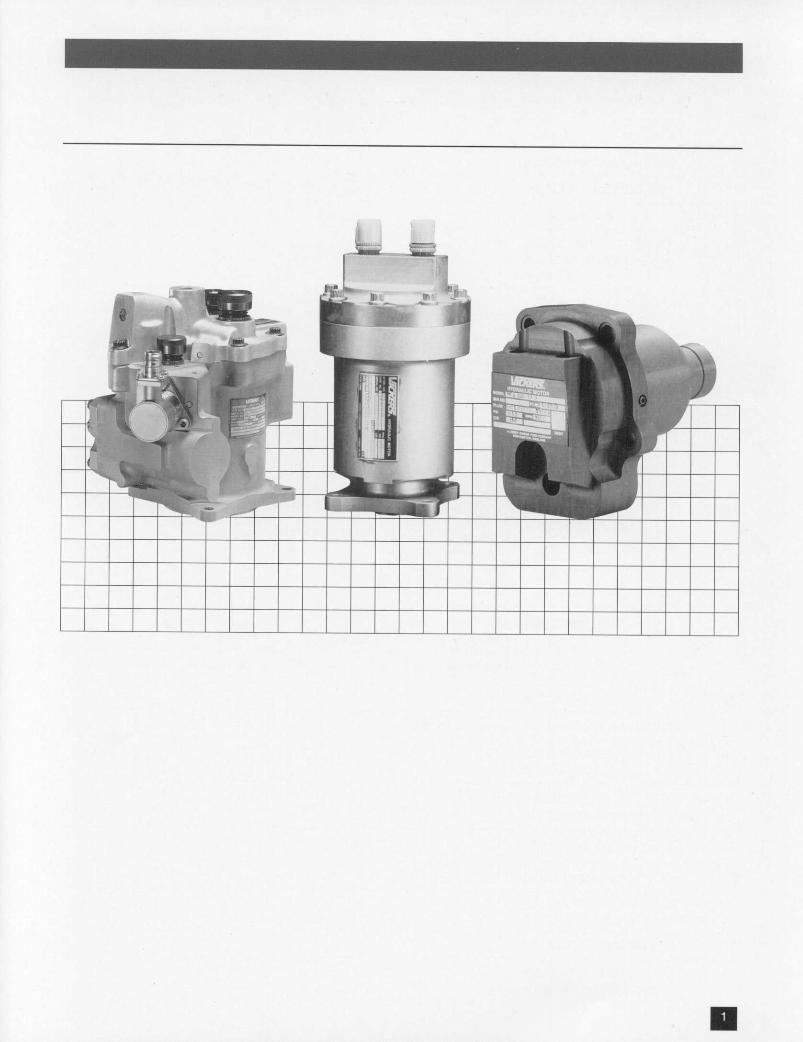
Since 1921 Vickers has gained vast package combined with high power
experience in the design and manu- output and a wide range of operating
facture of hydraulic equipment. This speeds. Operation may be continuous
experience has led to an established or intermittent, reversed or stalled
range of highly efficient, reliable and without damage when correctly integrat-
cost effective inline piston motors which ed within the overall system. The rate of
supply many applications. change in speed is limited primarily bythe rate at which the flow of hydraulic
This brochure is a technical description fluid is supplied to the motor and the
of the design, operation and perfor- inertia driven by the rotor shaft. Since
mance of the Vickers fixed and variable stalling does not cause damage
displacement inline motor series and the hydraulic motors are ideally suited for
variety of controls available. Intended engineered dynamic and static braking.
as a convenient reference for the systemdesigner, it provides basic information to The inline piston motor utilizes
predict unit performance and to select essentially the same rotating groups
the correct type of motor control. featured in the inline piston pump*.Minor differences in porting and in
Vickers hydraulic motors are uniquely piston shoe and cylinder block balance
suited for rotary power applications are used to give optimum torque output.
requiring a compact, lightweightHydraulic motors are typically used inapplications requiring the precise controlof rotary power to a mechanical device.Typical aerospace uses include theactuation of aircraft flap/slat and wing
sweep systems, power transfer, turbineengine starters and constant speeddrives plus other controlled powerapplications such as winch, fan, gener-
- ator, compressor and gun drives.Military vehicle and marine applicationsinclude azimuth and elevation servodrives for turret drive systems andmissile launchers plus winch andcooling fan drives.
Vickers hydraulic motors meet the needs of
a wide range of application and perfor-mance criteria. The Vickers hydraulic
motor family includes both inline and bentaxis motorst with displacements between0.03 and 4.25 in3/rev.
Inline Motor with integralcontrol valves
'The inline piston pump is featured in Vickersdescriptive summary SE-103.
tThe fixed displacement bent axis motor isfeatured in Vickers descriptive summarySE-104.

Proven Durability The basic inline motor concept hasremained unchanged since inception.However, through continuous develop-ment and product improvements, plusthe need to accommodate featuresdemanded by advances in hydraulicsystem requirements, the Vickers inlinemotor has evolved into a superiorproduct with proven durability.
Size Range Standard frame sizes range from 0.03 to4.25 in'/rev displacement. Customdesigns are available for specificapplications.
Horsepower/Weight Ratio Compact, lightweight package with highpower output.
Versatile Operation Continuous, intermittent or reversibleoperation; can be rapidly stalled withoutdamage, when correctly integratedwithin the system. High breakout torquecapability.
Predictable Performance Our in-house test data and informationgathered from field applications providedata to accurately predict performance,life expectancy and reliability of a unitfor virtually any set of operatingconditions.
Choice of Materials A wide selection of materials areavailable to meet individual systemneeds, such as high temperature orhazardous environment operations.
Low Power Loss The compact rotating group and smallanti-friction bearing diameters result inminimum power loss.
Reliability/Maintainability Simplicity and conservative designparameters assure high reliability andease of maintenance.
Application Flexibility The standard motor is used as a basisfor all applications. Controls are subse-quently added as an integral part of themotor or as separate sub-assembliesdependent upon the individualrequirement.

tl. me :2er TzIO "*lI~ R-I
Major Components of Vickers Fixed Displacement Inline Motor
Piston~ P. .h .
Sub ~ ~ ~ ~~ -- ^ -a,
._ : ' -~~~~~~~~~Anl----- _ _ , . .. _~~~~~~MOC
..... _ ..............PistonrSho
_~~~~~~~~~~~~~~~~~Hl Down Plat

The Vickers inline motor series is a drive shaft to rotate. The piston shoesfamily of positive displacement, axial are held against a bearing surface bypiston motors; both fixed and variable pressure. The shoe hold down platedisplacement designs are available. and retainer ring help maintain theFigures 1 and 2 are cross sections of proper mechanical configuration totypical fixed and variable displacement prevent tipping of the shoe bearingmotors, respectively (the displacement plate. The bearing surface is held at ancontrol configuration can be varied to angle to the drive shaft axis of rotationsuit the application.) by the angle block (fixed displacement)
As the pistons reciprocate within the or by the bearcng mounted yokecylinder block bores they cause the
Valve Plate Sleeve Piston & Shoe S/A Shaft Seal
Cylinder Block
figure 1 Retainer Ring /Spacer Angle Block Drive Shaftcross-section of a Shoe Hold Down Plate
fixed displacement motor
Power Stroke As each piston reaches top dead center tangential force which creates a torque(minimum cylinder volume), it is subject- on the cylinder block. The torque ised to inlet pressure by the valve plate transferred to the drive shaft through thepressure port and is thereby driven cylinder block spline. The sum of thedown the bore. The axial force of the individual piston torques comprises thepiston is applied through its shoe to the total torque developed by the motor.angle block (or yoke); due to the "downramp" effect, the piston exerts a
Exhaust Stroke As each piston reaches bottom dead The piston shoe now moves "up ramp"center (maximum cylinder volume) it and the piston forces the fluid in theopens into the outlet (low pressure) port cylinder into the outlet port. When thisin the valve plate. exhaust stroke is completed, the piston
is back at top dead center ready for thenext power stroke.

Developed Torque The total torque generated is propor- is possible to achieve a range oftional to the displacement of the motor displacements by altering the maximummultiplied by the differential pressure displacement angle and so match theapplied (inlet pressure minus outlet motor torque and speed to a specificpressure). The displacement increases application requirement.with the stroke angle of the angle block The inline motor obtains its high torque(or yoke), and therefore the developed efficiency by minimizing frictional losses .torque also increases with this angle. of the moving parts, including side loadsThere are lower and upper practical of the pistons. Lubrication betweendesign limits for this stroke angle. piston and bore, piston and shoe, and
The diameter of pistons, their number the bearing plate and shoes is effectedand stroke determine the motor through porting of high pressure fluid todisplacement. Piston stroke is propor- maintain hydrodynamic bearingstional to cylinder block bore circle between moving surfaces.diameter and the tangent of the displace- The precise design and manufacturement angle; the greater the angle, the result in a highly efficient, long lastinggreater the torque output for a given rugged hydrauic lor.piston diameter. Rated performance rugged hydraulic motor.angle for standard motors is 17 degrees30 minutes. Within a given frame size it
Retainer Ring
Piston & Shoe S/A _ Shat Seal
Cylinder Block Jn -
DriveShaft
_ Shoe Hold~~~S+ ~~~~Down PlateValve Plate Actuator Piston Yoke Yoke Spring
Assembly
figure 2cross-section of avariable displacement motor

m. - .7-MR070 0 M-l
Developed Torque (cont.) A hydraulic motor converts hydraulic As torque load changes, the tempo-fluid flow into rotary motion, and rary torque imbalance will produceconverts pressure differential across the acceleration or deceleration until aports into torque. This developed new speed is reached, at which timetorque, delivered to the output shaft is the delivered torque again equalsreduced slightly by internal losses load torque.(viscous friction, porting losses andwindage). The load on the shaft and the 2 if a flow control valve is used in thehydraulic circuit supplying the differen- motor inlet line to maintain a constanttial pressure will together determine the inlet flow, (such as in Figure 2.2, pagespeed and net output torque. The 21) the speed will be nearly constantfollowing two examples will illustrate this and pressure drop across the motorfor a fixed displacement motor: ports will be determined by the load
torque, with the remaining pressure1. If a constant differential pressure is drop taken across the valve. If the
maintained across the motor ports, load torque increases above a certainthe developed torque is constant: value, all of the available supplyspeed will be determined by the pressure is taken across the motortorque load on the shaft; since motor ports, and the flow control can notorque loss is speed dependent, the longer regulate speed; operation thenoutput torque will vary accordingly. reverts to the above example (1.)
system.
Angle Block
Piston & shoe Assembly
figure 3basic rotating group
(less shaft and bearings)of a fixed displacement
inline motor

Drive Shaft and Bearings The drive shaft, as illustrated in Figures windage losses. This is especially1 & 2, is a simple, single-piece design important in high-speed applicationsheld in accurate alignment by two anti- where the fluid disturbance and powerfriction bearings. loss in submerged bearings increases
Bearing Size Minimized appreciably with bearing speed and size.The shaft is supported at opposite ends Self-aligning Splineby one radial bearing and one radial- The splined drive shaft is a majorthrust bearing. Since radial loads, due diameter fit, crowned to maintain theto piston forces on the cylinder block, cylinder block in correct geometricare well distributed between these two relationship to the valve plate under allwidely spaced shaft bearings, their size operating conditions.is minimized reducing both friction and
Cylinder Block A hydraulic pressure balance is through the cylinder block spline,maintained between the cylinder block eliminating the need for a supportand the valve plate, Figure 4, minimizing bearing on the cylinder block.friction and reducing torque losses. Consequently, losses associated with
such a large bearing are eliminated. InThe cylinder block sprine is located near addition. this kind of load supportthe plane of rotation of the pis on shoes provides optimum alignment conditionsto minimize moments acting on the between the cylinder block, valve platecylinder block, and drive shaft, since fewer mating
No Support Bearing Needed surfaces are required to establish theRadial loads resulting from piston correct geometric relationships of thesereactions are carried to the drive shaft components.
Valve PlateSurface
Piston
ShoeCylinder
BlockPiston
figure 4 figure 5
Piston and Shoes Hertz stress criteria, combined with determined by pressure balance so thatverification tests, have been used to the resultant loads are adequatelyarrive at an optimum piston/cylinder supported by the fluid film under theblock design. Vickers also places shoe sealing lands, Figure 5.special emphasis on shoe design since Low Cylinder Bore Wearthis is a critical link in the efficiency, life, Piston engagement in the cylinder blockand reliability of the inline motor.
bore is accurately controlled so thatPrecise Pressure Balance reaction forces between the pistons andPrecise pressure balance versus speed cylinder block are minimized. Thisand load capability have been achieved reduces bore wear, hence leakageto assure maximum efficiency and life. remains virtually constant with time.Thrust loads on the piston shoes are
U

Angle Block The angle block provides a durable improved maintainability. Angular(Fixed Displacement) lapped bearing surface for the shoe retention of the block is provided by a
faces, to slide against. In some designs key which locks the sleeve, retainer ring,a separate shoe bearing plate supported spacer and angle block to the housing.by the angle block is needed for
Yoke The yoke, (Figure 6), must support the(Variable Displacement) full load of the pressurized pistons and
yet remain flat. Extensive studies havebeen performed on the yoke to provide /a design with an optimum deflection to iweight relationship. The piston load issupported by relatively small diameterpintle bearings (cylindrical roller type),which are mounted in the mountingflange.
A separable shoe bearing plate islocated within the yoke to provide anaccurately lapped bearing surface forthe shoes and permits optimum bearing -n--- Pnematerial selection. Piston -- W PintleCircle I
figure 6
Piston Shoe Alignment problems associated with the designed to prevent tipping of the pistonHold Down Plate guiding of the hold-down plate on the shoe by the plate, Figure 7.
outside or inside diameter are eliminatedby a design that achieves guidance by The size and locaru on of the holes in thethe piston shoes alone. plate are carefully determined to give
optimum driving surface contactThe position of this plate, with respect to between shoes and plate.the piston ball socket plane, has been
Piston
Hold-DownPlate shoe Hold-Down
Retainer Plate
k 5) 3 shoeSoBerng
fe 7Yoke
figure 7

Retainer Ring This stationary rings has a bronze face In fixed displacement motors, theto serve as a bearing surface for the retainer rings is secured between therotating shoe hold-down plate and spacer and sleeve.provides axial retention of the plate onthe exhaust stroke side during decel- in both fixed and varable motors, theeration of the shoes. retainer ring design and arrangement
assure the high-speed capability of theIn variable displacement motors, this motor.rings is secured to the yoke by screws.
Spacer (Fixed Displacement The function of this part is to provide the shoe flanges and hold-down plateMotors Only) accurate spacing between the retainer plus a small running clearance. In some
ring and the shoe bearing surface of the older designs the spacer is incorporatedangle block. This space is occupied by as an integral part of the angle block.
Valve Block This part provides a bearing surface for Valving(also called Valve Plate) the cylinder block, commutation of flow The valving is provided by two circular
(valving) with the cylinder block, support arc slots, which are either in the valvefor the drive shaft bearing and external block face, or (in the case of anports for inlet and return lines. In variable aluminum valve block) in a steel waferunits, the controls are incorporated in the plate sandwiched between the valvevalve block, or are attached to it. block and the cylinder block.
Water Plate TimingSome designs incorporate a separate For bidirectional motors, valve block kidneywafer plate between the valve block and slots are symmetrical about the Top Deadcylinder block to permit greater freedom Center (TDC) and Bottom Dead Centerin the choice of the valve block material (BDC) locations. Single direction motorsselection and to reduce the cost of employ optimized biased timing whichoverhaul. provides higher efficiency and reduced
output hydraulic pulsations Figure 8.
\ \ ~~~~~~~/Decompression
InletA Exhaust/Inlet Exhaust Exhaust I Inlet
Rotation~~~~~~~Ro to/ RRotation/P Precompression /j \
figure 8 Uni-Directional Bi-DirectionalRotation Rotation
Housing The housing of a fixed displacement and eliminates the need for seals at thatmotor includes the mounting flange as point. Pintle load is carried directly toan integral part. This eliminates an the mounting flange. In both fixed andexternal housing seal and a bolted variable motors, the housing is designedinterface. In variable displacement to provide maximum strength withmotors the housing encloses the pintles minimum weight.
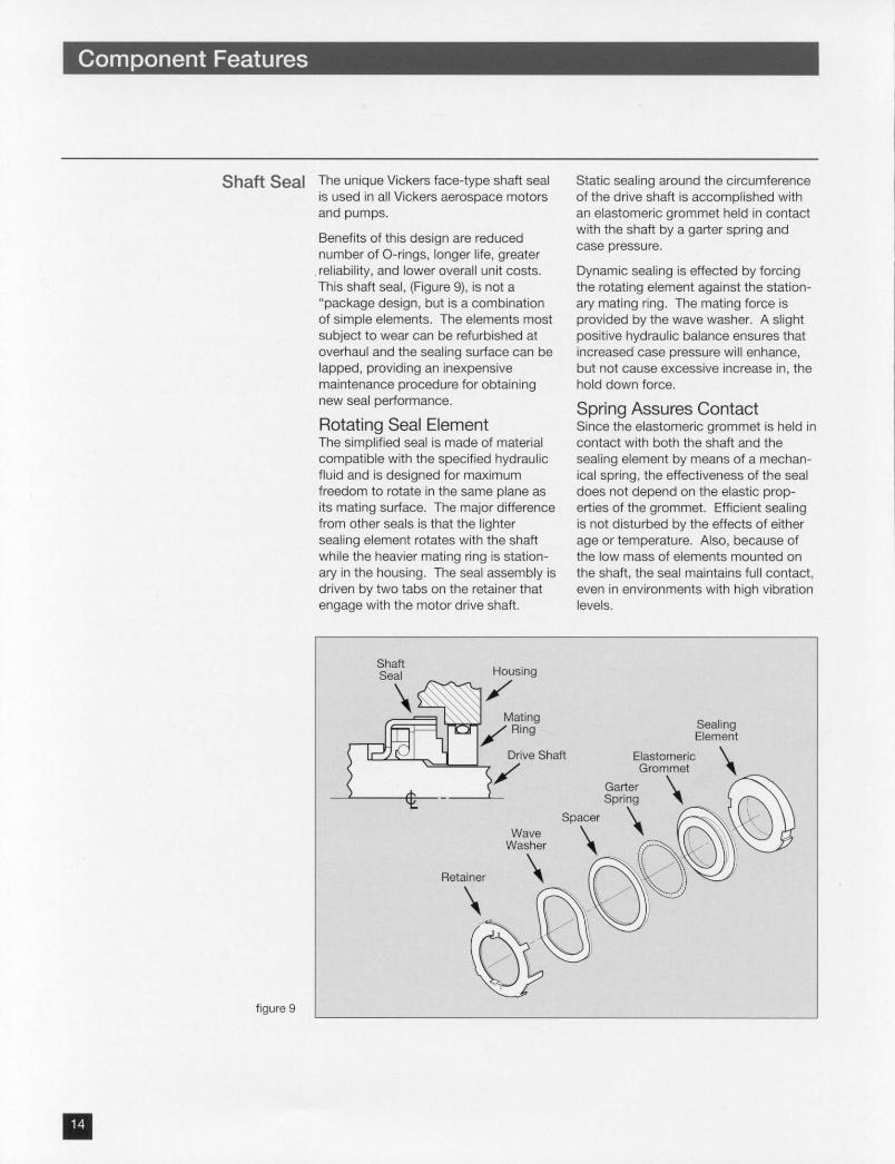
Shaft Seal The unique Vickers face-type shaft seal Static sealing around the circumferenceis used in all Vickers aerospace motors of the drive shaft is accomplished withand pumps. an elastomeric grommet held in contact
with the shaft by a garter spring andBenefits of this design are reducednumber of O-rings, longer life, greater case pressure.reliability, and lower overall unit costs. Dynamic sealing is effected by forcingThis shaft seal, (Figure 9), is not a the rotating element against the station-"package design, but is a combination ary mating ring. The mating force isof simple elements. The elements most provided by the wave washer. A slightsubject to wear can be refurbished at positive hydraulic balance ensures thatoverhaul and the sealing surface can be increased case pressure will enhance,lapped, providing an inexpensive but not cause excessive increase in, themaintenance procedure for obtaining hold down force.new seal performance. Spring Assures ContactRotating Seal Element Since the elastomeric grommet is held inThe simplified seal is made of material contact with both the shaft and thecompatible with the specified hydraulic sealing element by means of a mechan-fluid and is designed for maximum ical spring, the effectiveness of the sealfreedom to rotate in the same plane as does not depend on the elastic prop-its mating surface. The major difference erties of the grommet. Efficient sealingfrom other seals is that the lighter is not disturbed by the effects of eithersealing element rotates with the shaft age or temperature. Also, because ofwhile the heavier mating ring is station- the low mass of elements mounted onary in the housing. The seal assembly is the shaft, the seal maintains full contact,driven by two tabs on the retainer that even in environments with high vibrationengage with the motor drive shaft. levels.
Shaft HousingSeal
Mating Sealing7 Ring Element
Drive Shaft Elastomeric< ._ 7 a/ Grommet
< < ¢t ~~~~~~~~Garter \
Wave SpacerWasher
Retainer
figure 9

* * -
External Sealing The number of external seals is kept to a addition to the shaft seal and ports.minimum, thereby reducing the number Variable displacement units have twoof potential external leakage paths. external seals in addition to the shaftVickers fixed displacement motors seal and ports, plus those required fornormally have only one external seal in the controls.
Materials Conventional, easily worked materialsare used in the Vickers inline motordesign. Materials typically includebronze (cylinder block, shoes andretainer ring), carburized or tool steel(pistons, drive shaft, bearing plate,piston shoe hold down plate and waferplate) and aluminum (housing and valveblock).
For operation in conditions beyondthose normally encountered, it ispossible to use alternative materials inthe construction of the motor. Pleaseconsult your Vickers applicationengineer.

The hydraulic motor used on a modern aircraft or defense system is a criticalcomponent and therefore requires careful consideration. Determining the correctmotor for a specific application involves several basic considerations.
Performance Certain standards and details of specifications is an important criterion.performance are required by system Vickers inline motors performance isdesigners, typically MIL-M-7997. indicated by the followingThe ability to meet or exceed these characteristics.
Reliability The safety of an aircraft, the effective- essential objective in all design,ness of a missile, or the reliability of a manufacturing, and testing operations.defense vehicle often depends on the This objective is carried through thecorrect functioning of the hydraulic service life of a motor by Vickerssystem. Understanding the product through comprehensive Productreliability is an important factor to the Support and statistical studies of motorscustomer. Vickers sets this as an in use.
Economy Unit cost involves both original purchase Vickers inline motors, their provenprice and operating cost. The operating reliability and long life, provide bothcosts, in turn depend on overhaul time, original purchase and operating econ-cost of rework and replacement parts, omy. Minimum life cycle cost is theand unscheduled removal rates. The result.simplicity and low number of parts in
Low Moment of Inertia The basic design of the inline motor example, it is possible to reversepermits rotating components to be kept direction at rated speed in approx-to a minimum size. Thus the moment of imately ten milliseconds, with no loadinertia is kept low, ensuring high inertia, without incurring damagingresponse to changes in pressure. pressure overload surges. Increasing
load inertia would extend reversalLow inertia and attention to design in the response times accordinglyinline motors permit rapid changes inrotational speed and direction. For
Break-away Torque The low static friction of the motor . Pressure lubrication of the pistonsresults in high torque availability at and hydrostatic bearing design of themotor break- away; this is achieved by piston shoe surfaces.the following: * Optimum hydraulic balance at the
* Use of low friction roller and angular valving face of the cylinder block andcontact ball bearings for supporting piston shoes to ensure maximumthe drive shaft. torque output, while maintaining high
volumetric efficiency.

mm
Stall Torque The inline motor is capable of being circuit which takes advantage ofstalled without damage provided the dynamic braking. Please consult yoursystem prevents surge pressures Vickers application engineer for furthergreater than the proof pressure limit of assistance in such applications.the motor. It is thus possible to design a
Constant Output Torque Torque output of the hydraulic motor is speed range, dropping slightly due toa function of unit displacement and windage and porting losses as speedpressure drop across the motor. Torque increases.is nearly constant throughout the design
Efficiency Typical efficiency of Vickers 3000 psi Efficiencies are maintained near these(207 bar) inline motors at rated operating values for long operating periods,conditions are indicated below: dependent on the system conditions
Typical Efficiency* ~and requirements. Vickers applicationsTypical Efficiency* engineers are able to advise you on your
Volumetric Torque Overall particular requirement.
Breakout N/A 75% N/A
Running 95% 90.5% 86%
Stall N/A 92% N/A
Dynamic Braking A hydraulic motor can be used for intermittent, continuously reversed ordynamic braking as long as the system stalled without damage if the system inis protected against excessive pressure which the motor operates is correctlysurges. Operation can be continuous, configured.
Weight Vickers inline motors have high power to rating). Higher power to weight ratioweight ratio. Typical of the range is the may be obtained in intermittentMF3-115 motor with a ratio of 4.9 output applications.horsepower per pound (continuous
Temperature Range Vickers inline units are designed to temperature). Special modifications forprovide optimum performance in a Type operation at higher temperature are11 system as defined by MIL-H-5440G detailed in the following section.(-65' to 2750F/-540 to 1350C fluid
Torque efficiencies are valid at rateddifferential pressure and volumetric efficiencyat rated speed. See tables A and B for ratedcharacteristics.

Ambient Conditions Vickers inline motors can be operated in Ambient temperature has very littleextremely adverse ambient conditions. effect, provided that the fluid remainsThey can be submerged in fluid, below the critical temperature of the sealoperated in a vacuum or in any type of compound. For example, a unit withatmosphere providing it is compatible fluorocarbon seals (rated at 4500F maxwith the motor housing and sealing has passed a 5 minute, 20000 F (1 093GC)materials. Special materials are flame test.provided for extreme environments.
Motor/Pump Operation Vickers inline motors can be operated aspumps in both directions of rotation.For a unit which operates as a motor inone direction of rotation and as a pumpin the opposite direction (such as a hoistwinch motor or as a PTU motor/pump,mentioned below), timing optimizationgives high efficiency and low pulsationswhen operating both as a motor and asa pump.
Power Transfer Unit In many applications it is desirable totransfer hydraulic power from onesystem to another. For example, to sizethe main engine-driven pumps of anaircraft to provide the maximum powerrequired by each system would result inadded cost, weight and space of themain engine pump. An alternative is theuse of a power transfer unit (PTU) toprovide the supplementary powerbetween systems, while keeping thefluid systems entirely separate. ThePTU can consist of two motor unitsmounted back-to- back, configured toprovide the specific performancenecessary for a particular application.
One unit acts as a motor and the otheras a pump, for unidirectional transfer offluid power; or each can serve as bothmotor and pump for transferring fluidpower in both directions between thetwo hydraulic systems.
The PTU can be left on-line at all times,since stalling does not affect the inputunit (motor) or output unit (pump). Whenthe differential pressure between systemsfalls below a given level the unit on thehigh pressure side operates as a motordriving the other unit as a pump supply-ing auxiliary power to the low pressuresystem.

Case Drain Case draining of the motor can beachieved by either of the followingmethods. The first is by providing areturn line for porting case drain flowfrom the motor to the reservoir. Thesecond method is by use of an integralcheck valve to internally port case flowto the motor outlet for a unidirectionalrotation of the motor. This valvemaintains case pressure slightly abovemotor discharge pressure, and preventsback flow from motor discharge tomotor case. In applications where themotor must operate in either direction ofrotation, two check valves are used toport case flow to low pressure line.
High Temperature Motors Vickers inline motors are capable ofoperation in Type II systems (-650 F to2750F/- 540C to 1350 C). For fluidtemperatures above 3000F/149cCplease consult your Vickers applicationsengineer.
Vickers has extensive experience withhigh temperature motors. Thousands ofhours of field experience with unitsoperating at temperature of 3000F/1490Chave been accumulated on fluids.Ambient temperatures in theseapplications have ranged up to900cF/4820 c.
Technical Support Before a motor can be designed andperformance predicted with accuracy,detailed information on the application,fluid, and temperatures must be known.
Engineering Teaming Close and active engineering teamingwith the customer is aimed at providingthe optimum hydraulic circuit designnecessary to obtain the most reliablemotor performance.

Established Data The wide use of Vickers inline motors in The Vickers inline motor design is anall types of military and civil applications, extremely versatile unit. Variations ofand the record these units have estab- the highly reliable Vickers inline motorlished over the years are evidence of can be provided, such as cartridge andtheir reliability, performance and reverse ported configurations. Thesesuperior design. alternatives can provide additional
weight savings and/or reduced envelopeVickers application engineers will be weight s or reue d envoperequirement, for integration into apleased to work with you in selecting the customer's subsystem.configuration to meet the needs of yourhydraulic system.
Cartridge Design This design enables the motor to be specific application to provide aneasily integrated within a customer's integrated drive package with reducedsubsystem. The highly reliable inline envelope dimensions and added weightmotor can be configured for each savings.
Reverse Ported Due to space restrictions in certain and drive shaft connections are made atsystem configurations, it may not be the same face.possible to use a standard inline motorwhere the hydraulic ports are at one end The units featured above are just twoand the drive shaft connection is at the examples of Vickers design flexibility.Opposite end. Additional solutions to meet special
requirements can be discussed withTo solve this problem, Vickers has your Vickers application engineer.developed a unit where both hydraulic
Cartridge and reverse-ported motors
U

The following schematics indicate thetypes of control that can be integrated intothe Vickers fixed and/or variable displace-ment inline motors.
1 - Cross Port Relief Valves(for overload protection) Pressure/Return
Return/Pressure
2- Speed ControlConstant Speed Hydrostat(Single Direction Rotation) Pressure
L… - --- Return
2.2 -Flow Control(Dual direction rotation) 1 1speed limiting with cross port Pressure/Returnrelief valves for overloadprotection
/ I A, __T ic_ Return/Pressure
3.1 -Directional ControlOn/Off Controlwith anti-cavitation valve fordeceleration
Pressure
/~~~~~~~~~~Rtr
U

0 0A We
3.2- Bi-Directional Controlwith cross port relief fordynamic braking
Pressure
Return
4- Directional & Speed Controlwith cross port relief andanticavitation valves fordynamic breaking
V rx Lv 4 > : - L Pressure
T / L Return
5-Constant Speed, VariableDisplacement(with isolation valve) Pressure/Returncontrolled speed (bi-directional)or torque controlled (bi-directional)
K Return/Pressure
6- Dual Displacement(solenoid control)Dual speed
IUi < I Pressure
L 67 *= Rturn

* --m"
Equations and Tables AMERICAN STANDARD
Tables A and B (p.26-27) list certain 1). Flow a = in3/rev. x rpm (gpm)fundamental characteristics of Vickers 231inline hydraulic motors. The following
text explains the calculations on which 2). Torque T = in3/rev. x psid (lb-in)the figures in these tables are based, 2
and some of the general relationshipsbetween theoretical and practical values. 3). Power (Shaft) hp = Torque x rpm (hp)
Some equations useful in connection 63,025with the Tables are listed on the right. 3a). Power (hydraulic) hp = gpm x psid (hp)
All units are as given in the tables.Inertia used in these equations is the 1714sum of the value given for the motor 4). Angular Acceleration c = Torque (rad/sec 2)plus the load inertia reflected at the inertia
motor shaft.5). Time to stop t = n x Inertia x rpm (sec)
(or to reach speed) 30 x Torque
6). Rev. to stop 0 = ir x rpm2 x Inertia (rev)(or to reach speed) 3600 x Torque
WHERE: Torque = Ibf-inInertia = lbf-in-sec2gpm = U.S. galmin
METRIC UNITS
1). Flow 0 = mUrev. x rpm (Umin)1000
2). Torque T = mUrev. x bar (N-m)20n
3). Power (Shaft) W = it x Torque x rpm (watts)30
3a). Power (hydraulic) W = 5/3 x Umin. x bar ' (watts)4). Angular Acceleration oc = Torque (rad/sec 2)
Inertia
5). Time to stop t = X x Inertia x rpm (sec)(or to reach speed) 30 x Torque
6). Rev. to stop e = 7r x rpm2 x Inertia (rev)(or to reach speed) 3600 x Torque
WHERE: Torque = N-m (Newton metre)Inertia = kg-rn (kilogram metre)
* KPa/1 00 or 1 0 mPa may be used in place of bar
The equations give theoretical values. For Substitution of actual torque in equations 3,actual torque, multiply by torque efficiency. 4, 5 and 6 will, of course give actual, asFor actual flow, divide by volumetric opposed to theoretical values.efficiency.

Important Notes Efficiencies stated herein apply to a High pressure motor designs of 4000,motor with a 3000 psi (207 bar) differ- 5000 and 8000 psid (276, 345 and 522ential pressure operating at rated speed, bar) are also available. The basic designand fluid viscosity in the range of 3 to 30 is the same as the 3000 psi (207 bar)cs. For motor operation outside these motor series, however, performance andvalues please consult your Vickers proportions are different. For operatingapplication engineer. conditions that are not at rated speed
and differential pressure, use the proce-dure below to obtain torque and flow.
A. FLOW1. CALCULATE FLOW LOSS USING THE FOLLOWING EQUATION:
Qloss = (.05 Orated) ( i
Where Q ratid s theoretical flow at maximum displacement and rated continuous speed, usingequation 1 or Table A or Table BPinlet is motor inlet pressure, psi(for Pinlet in metric units, substitute with the metric equivalent of 3000 psi, e.g. 207 bar)Flow loss is essentially independent of speed and stroke angle.
2. THEN MOTOR CONSUMPTION IS:
Qinlet = Qtheo + Qloss
Where Qtheo is theoretical flow calculated at the given speed and displacement value, using eqn 1.
Example:Find the typical value of flow consumption for an MF3-115 motor at 2500 psi inlet pressure and 5500rpm; assume that the motor has a reduced stroke angle which gives 1.00 in'/rev displacement. Thenby equation 1 (page 23)
Qrated = (1.15 in3/rev)(6600 rpm) = 32.9 gpm231
(Note that maximum displacement and rated speed are used here; Table A can also be used toobtain the 32.9 gpm value.)
° loss = (.05) (Crated) ( 3in)et (-05) (32.9) (3000) 1.4 I3000 (.5 329(500)0 . p
By eqn 1. Qtheo = (1.00 in3/rev)(5500 rpm) = 23.8 gpm231
Then Qinlet = 0theo + QCos = 23.8 + 1.4 = 25.2 gpm
B. TORQUE1. CALCULATE TORQUE LOSS USING THE FOLLOWING EQUATION:
T =oss = Trated ( N I + 0.0316N rated
Where Trated is evaluated from equation 2. at maximum displacement and 3000 psid (or the metricequivalent, 207 bar)N is the speed at which the torque loss is required.Nrated is the continuous speed rating (Table A or Table B)
(At speeds less than approximately 10% rated, torque loss begins increasing again: for speedshigher than 110% rated, the torque loss begins increasing somewhat more rapidly. Therefore theabove equation should not be used outside of the 10% to 10% speed range.)
2. THEN, MOTOR OUTPUT TORQUE IS:
Toutput = Ttheo + Tloss
Where Ttheo is evaluated from eqn 2. for the given displacement and differential pressure values.Torque loss is essentially independent of pressure and stroke angle.
Example:Find the typical value of output torque for the values given in the previous example. Then by equation2 (page 23):
Trated = (1.15 in /rev)(3000 psid) = 549 lb-in2 n
(Note that maximum displacement and 3000 psid are used here; Table B can also be used to obtainthe 549 lb-in)
Tioss= -Trated) N + 0.03) = (549) ( 5500 + 0.03) = 45 lb-in1 6 Nrated 1 6x6600
By eqn 2, Ttheo = (1 00 in3/rev)(2500 psid) = 398 lb-in
Then Toutput = Ttheo + T1oss = 398 -45 = 353 lb-in
The above method of calculation should be used only for the normal operating range offluid temperature and speed. The results obtained should only be used as a guide fortypical performance and should not be used to establish minimum specification values.For fluid temperatures below approximately 500F (1 OC), and speeds outside the rangestated above, consult your Vickers application engineer.

E X o e X c RecoMaximum Rotating GroupBasic Model Number E0 .. 0 a ERcm ede oa Mmn fWeight (Ibs)E 0 0~ igRcmmene Poa Mmnto
Speedat3000 psi Inertia E X 5IS E Il t D-' a 0
ii Si ~.030 2.53 14.3 4.43 19,000 24,300 .012 .30x10' .7x 10' .20 .18 0.9 1.1
es. St. .06 3.90 28.6 6.82 15,000 18,750 .036 .96x104 .9x10' .29 .28 1.4 1.7
hZ 65t ~.082 4.97 39.2 9.63 14,000 17,500 .040 l. OxlO 10'l.5xl07 .36 .35 1.7 2.0
(.11 5.95 52.5 10.4 12,500 15,600 .10 2.6x10⁴ 1.L"' .42 .4 2.1 2.
U , * ~~~.16 8.66 76.4 15.2 11,000 13,750 .19 4.9x10⁴ 1.2x10⁷ .54 .60 2.8 3.2
* 3 .22 9.52 105 16.7 10,000 12,500 .32 8.3x10' 1.3x10⁷ .64 .64 3.5 4.1
* 5 32 12.5 153 21.8 9,000 11,250 .60 16x104' 1.5x10/ .92 .86 4.6 5.4
.44 15.2 210 26.7 8,000 10,000 1.0 26x10' 1.7x10' 127 1.0 5.8 6.9
e~~~~~~~~~~~~~~~~~~~~~~~
* .56 19.9 267 34.8 8,200 10,250 1.0 26x10' 2.7x10⁷ 1.62 1.2 5.4 6.2
* I ~~~.75 22.7 358 39.8 7 ,000 8,750 1.6 41 x1 04 3.l xlO7 2.1 7 1.5 6.8 7.9
= ~~~~1.15 32.9 549 57.5 6,600 8,250 3.2 83X104' 3.6X10⁷ 3.32 2.1 9.7 11.2
* 6!| 1.50 39.0 716 68.2 6,000 7,500 5.0 130X109 3.9X19' 4.33 2.5 12.3 14.3
1 2.40 55.1 1146 96.4 5,300 6,600 11.0 285X10' 4.6X10⁷ 6.93 3.5 19.1 22.5
SI 3.00 64.9 1432 114 5,000 6,250 160 .415X10- 4.9X10' 8.66 4.2 23.3 27.5
4.25 82.9 2029 145 4,500 5,500 29.0 750X10 4 5.sX1O' 12.3 5.3 32.0 38.
U ~ ~ ~~~~~~1 .5 5. 04 1,0 560 .0 26l0 .x0 4 4 . .

X - 2 e ~~~~~~~0 - -B a s c M d e l N u m e r - w M a x im u m t e g t ( gBasic Mdel Num er .Recommended Speed oWehtkg
i ~~~.49 9. .2 32 1 00 24,30 .041 .7x0 .0 .4 . .
1.34 18.8 4.42 6.5 14,000 17,500 .01x103 1 207 barAp (rpm) 9 .08
= $ 22.5 5.93~~2 7C.8 250 1,0 0x00.X0 688 .0 . .
l l.2 2og88 . 1,0 375 0x0 1.3x10 8.85 .4 1.2.
0 0~~~~~~~~
3.61 6.1 1.87 2.4 0,001,0 Ox0 x0. 05. .6 1.T
>0
O
I2o
52.49 9.3 1.62 3.2 19,000 24,300 .004x103 0.7x10' 3.30 .043 0.4 0.5
* .98 14.7 3.24 5.1 15,000 18,750 .29X10 1.0x10' 4.75 .067 0.6 0.8
i i: so: 1.34 18.8 4.42 6.5 14,000 17,500 .01x10 3 1.7x10⁸ 5.90 .083 0.8 0.9
* S 1.80 22.5 5.93 7.8 12,500 15,600 .03x1O0 1.2x110 6.878 .100 1.0 1.1
* S * ~~2.62 28.6 8.63 9.9 11,000 13,750 .06x1& 1.3x10⁸ 8.85 .14 1.3 1.5
* I 3.61 36.1 11.87 12.4 10,000 12,500 .09x6104 1.5x10' 10.5 .15 1.6 1.9
* 6 5.24 ~~~47.2 17.27 16.3 9,000 11,250 .18x-10 3 1.7x10⁶ 15.1 .20 2.1 2.4
* 39 7.21 57.7 23.74 19.9 8,000 10,000 .29x10' 1.9x10⁶ 20.8 .24 2.6 3.1
* * 6 * ~9.18 75.2 30.21 25.9 8,200 10,250 .29x103 3.1 x1 06 26.5 .29 2.4 2.8
* S ~~~12.3 86.0 40.47 29.7 7,000 8,750 .47x101 3.5x10e1 35.6 .36 3.1 3.6
18.8 124.4 62.05 42.9 6,600 8,250 .94X1 0 4.1X10 54.4 .50 4.4 5.1
I 24.6 147.5 80.93 50.8 6,000 7,500 1.46X1W 4.5X1 9 71.0 .59 5.6 6.5
* S 39.3 208~~.4 129.5 71.9 5,300 6,600 3.22X1 0- 5.2X1 06 113 .83 8.7 10.2
6 49.2 245.8 161.9 84.7 5,000 6,250 4.68X10' 5.6Xl10 142 1.00 10.6 12.5
-69.6 313.4 229.3 108.1 4,500 5,600 8.49X10' 6.2X10⁶ 202 1.26 14.5 17.3

l - 0S -f
With the motor shaft unloaded, and These values are not quite attainable in3000 psi (207 bar) suddenly applied practice because of motor flow andacross the ports until maximum torque losses, and because valvescontinuous speed is reached, the impose a time delay in applying thetheoretical values for equations 4, 5 and pressure; however, they are an6 on page 23 are as follows. indication of the extremely rapid
response of Vickers inline motors.
| MODEL ACCELERATION TIME TO REACH REVOLUTIONS(rad/sec2 ) SPEED (sec)
4.8 x 10' .0042 .66
3.2 x 10⁵ .0052 .66
3.9 x 10' .0037 .44
2.0 x 10⁵ .0065 .68
1.6 x 10⁵ .0074 .68
1.3 x 10⁵ .0083 .69
1.0 x 10' .0096 .72
.81 x 105 .0105 .70
1.0 x 10' .0084 .57
.87 x 1 05 .0084 .49
.66 x 105 .0104 .57
.55 x 1 05 .0114 .57
.40 x 105 .0138 .61
.35 x 1 05 .0152 .63
.27 x 105 .0174 .65

20,000 200 _ _ _ _ 7_ 20
18,000 180 no. of bar = .06895 x no. of psi _ no18 .of 1 n. lb-in
U 16,000 160 - no. of kPa =6.895 x no. of psi - _ _ _ 16 6f = 0 o -no. of MPa = .006895 x no. of psi
14,000 a 140 4E 140z
12,000 120 =. = 142 __ 2__
10000 0100 2000 10 ° 20 400 2 0C,~~~~~~~~~~~~~~~~~~~~~~~~~~~O
di~~rssr -_ psi toqe-bi
8000 280 r20_6000 60 ___6 ___ _____
4000 40 _____no. of psi = 14.50 x no. of bar 4 __ ___
no. of psi = .1345 x no. of kPa no. of lb-in 8.851 x no. of N-rn2000 20 no. of psi = 145 x no. of MPa 2 _ /
0 0 1000 2000 3000 0 20 40 60 80 100 120 140 160
pressure - psi torque - lb-in
240 1240 ___ ____
200 1___ ______ __ 200 ___ ______
no. of Llmin = 3.785 x no. of gpm no7fm 639xn.o nno. of LUsec = .0631 x no. of gpm
160 ~-160 __
E
E120 ~,120
E0
80 80 ___
no. of in3 0.061 02 x no. of mL
40 40 ______
n.of gprn - 0.2642 x no. of IUminno. of gpm = 0.2642 x IUrin
5 10 15 20 25 30 35 40 0 2 4 6 8 1 0 12 1 4 16flow - gprn volume - in 3

The Fluid Power Division of Vickers The strategic location of Vickers designAerospace Marine Defense Group is a engineering, product support, andworldwide supplier of advanced production facilities throughout thetechnology hydraulic, electrohydraulic, world ensures that we will remainelectronic power and motion control responsive to our customers' needs.components and systems foraerospace marine, and defense Reliable products and comprehensiveapplications. product support have made Vickers the
leader in aerospace, marine, andVickers has major manufacturing and defense fluid power worldwide.service center facilities located in theUnited States, United Kingdom,Germany, and Japan, which aresupported by a worldwide network ofsales and service offices.
A Manufacturing
* Service Centers
* Sales
att
UbA

United States United Kingdom Italy
Vickers, Incorporated Vickers Systems Ltd. Vickers SystemsFluid Power Division Fluid Power Division Div Trinova SpA5353 Highland Drive Larchwood Avenue Via Monzese, 34Jackson, MS 39206-3449 Bedhampton 1-20060 VignateUSA Havant, Hants P09 3QN MilanoPhone: 601-981-2811 England ItalyFax: 601-987-3371 Phone: 0705-487260 Phone: 02-95058-222Telex: 62915661 Fax: 0705-492400 Fax: 02-9566730Easylink: 62915661 Telex: 86749 Telex: 333217
Vickers, IncorporatedFluid Power Division Germany Japan1755 DixonRedondo Beach, CA 90278 Vickers Systems GmbH TOKIMEC, IncorporatedUSA Fluid Power Division Aero & Defense DivisionPhone: 310-372-1530 Froelingstrasse 41 16-46 Minam-Kamataz-Fax: 310-372-2860 Box 2444 Chome
61294 Bad Homburg Ohta-Ku, Tokyo 144Vickers, Incorporated Germany JapanFluid Power Division Phone: 6-172-150 Phone: 03-3737-864112 Woodcliff Drive Fax: 6-172-15388 Fax: 03-3737-8668Simsbury, CT 06070 Telex: 415148 Telex: 0246-6193USAPhone: 203-674-8522Fax: 203-674-8398 France
Vickers, Incorporated Vickers Systems S.A.Fluid Power Division Box 60816710 NE 79th Street Ave. Du Chateau ZI Du VertSuite 201 St. Ouen L'Aumone, 95310Redmond, WA 98052 FranceUSA Phone: 1 34 32 32 01Phone: 206-869-8639 Fax: 1 30 37 54 96Fax: 206-869-5169
Vickers Systems S.A.Vickers, Incorporated Fluid Power DivisionFluid Power Division 15 Chemin de Paleficat3228 Rimhill Road 31075 Toulouse CedexLa Crescenta, CA 91214 FranceUSA Phone: 61 26 45 37Phone: 818-409-1574 Fax: 61 48 71 61Fax: 818-249-9140 Telex: 530820 F

Notes
U

FPD 3/95 ATRIMOVACompany© 1995 Vickers, Incorporated. All rights reserved.