for pictures and general information, visit us at completed catalog - rev 06-2009.pdf · linear...
TRANSCRIPT

Hero FabriDuct, LLC 5344 Ringgold Road Chattanooga, TN 37412 Ph.: 423-510-8225 or 877-HERO AIR Fax: 423-510-8330 www.herofabriduct.com Revised: 06/2009
Hero FabriDuct, LLC 5344 Ringgold Rd.
1 (877) HERO AIR Ph (423) 510-8225
FAX (423) 510-8330 Email: [email protected]
For pictures and general information, visit us at:
www.herofabriduct.com

Hero FabriDuct, LLC 5344 Ringgold Road Chattanooga, TN 37412 Ph.: 423-510-8225 or 877-HERO AIR Fax: 423-510-8330 www.herofabriduct.com Revised: 06/2009

Hero FabriDuct, LLC 5344 Ringgold Road Chattanooga, TN 37412 Ph.: 423-510-8225 or 877-HERO AIR Fax: 423-510-8330 www.herofabriduct.com Revised: 06/2009
Table of Contents
Hero FabriDuct™: An Introduction
Indoor Air Quality
Cost Comparison vs Metal
Displacement Ventilation
Technical Information
Fire/Smoke Requirement
ASTM E Test Report
Sound Data
Throw Information
Linear Slot Orientation
Design Elements
Fabric Options
Spec Sheets
Color Chart—8.1 Polyester
Perma Form Ribs
Suspension Systems
Installation Estimator
Quote Checklist
Installation Instructions
Washing & Storage Instructions
Frequently Asked Questions
Warranty Program
Page 4
Page 5
Page 6
Page 7
Page 11
Page 12
Page 13
Page 16
Page 17
Page 18
Page 19
Page 21
Page 22
Page 29
Page 31
Page 32
Page 35
Page 36
Page 37
Page 43
Page 44
Page 46
For pictures and general information, visit us at: www.herofabriduct.com
CONTACT INFORMATION: [email protected]
1 (877) HERO AIR Ph (423) 510-8225
FAX (423) 510-8330
Hero FabriDuct, LLC 5344 Ringgold Rd. Chattanooga TN 37412
Hero FabriDuct, LLC 5344 Ringgold Road Chattanooga, TN 37412 Ph.: 423-510-8225 or 877-HERO AIR Fax: 423-510-8330 www.herofabriduct.com Revised: 06/2009
• Heated or unheated makeup air systems • Air transfer systems: heated, unheated, or cooled, or • General ventilation systems
• The Client is always first. We are in business to serve our clients. Without them, there is no corporation.
• The corporation is always second. Without the corporation, there are no employees. • The employee is always third. Everyone employed by the corporation, including the
president, is an employee.
History of Fabric Air Ducting
Fabric air ducting has been in use since 1948. In 1963 Fabric air tubing was developed for heat-ing and ventilating in the greenhouse industry with only one diameter of tubing available. Holes were punched manually with a rubber mallet. Since then, the tubing has been diversified consid-erably in size, shape, and application. Not only is it still used in greenhouses, but is now used for a wide range of manufacturing and industry applications, as well as commercial, retail, office and school environments.
Hero FabriDuct, LLC
For more than 25 years, we have been servicing the Southeast's HVAC needs.
We custom engineer your system to the specifications of your application and space. Your system will be adaptable and versatile, and can be used with various heaters, fans, and air recovery units. Whether you are considering:
Mission Statement }
At Hero FabriDuct™, we strive to achieve long term, mutually beneficial relationships with our clients, vendors and employees. The value system we adhere to in order to maintain these relationships, and to ensure our growth, is based on the Judeo-Christian Code. The Judeo-Christian Code has its foundation in the Old and New Testament of the Bible, and is the basis for the value system of the free world, i.e., western civilization. The values of our corporation are based on biblical principles, and we adhere to the following priority of importance:
TO OUR CLIENTS:
If your project exceeds our capability, we will refuse it, with your best interest in mind. If we make a mistake, we will accept full responsibility for correcting it. If you make a mistake, we will work with you to correct it in the most efficient way possible. If you are satisfied with our work, our relationship will be a profitable one for the both of us. Our job is to help you increase your sales and profits by providing you with a quality prod-uct delivered on time. Success in that ensures our future.
4
By honoring this order of priority, Hero FabriDuct™ will attract and retain new customers, the corporation will prosper, and the benefits will flow to customers, vendors, and employees.

Hero FabriDuct, LLC 5344 Ringgold Road Chattanooga, TN 37412 Ph.: 423-510-8225 or 877-HERO AIR Fax: 423-510-8330 www.herofabriduct.com Revised: 06/2009
5
• Improving Indoor Air Quality while greatly reducing energy costs
• Improving workplace climate for maximum productivity
• Meeting all building codes and requirements for added peace of mind
• Cutting the costs associated with metal ducting by as much as 80%, in
addition to the above mentioned benefits
• Acting as a secondary filter
• Reducing growth of micro-organisms and bacteria, as our woven
polyester ducts discourage condensation
Hero FabriDuct™ offers effective, proven fabric air duct solutions
Improving Indoor Air Quality through innovation... Hero FabriDuct™ provides appealing, inexpensive solutions for:
Hero FabriDuct™ offers the added benefits of:
Indoor Air Quality (IAQ) deals with the content of interior air that could affect health and comfort of building occupants. In fact, indoor air is often a greater health hazard than the corresponding outdoor setting. Maintaining good (IAQ) indoor air quality is very important. As a professional, you are being called upon to identify and correct the factors impacting air quality and overall indoor comfort. Common indoor air pollutants include tobacco smoke; biological agents like animal dander, bacteria and mold; airborne particulates; volatile organic compounds like glue, solvents, cleaning agents; carbon dioxide and carbon mon-oxide; and pesticides. Many of these materials are found in minute amounts in most indoor environments. Add humidity and temperature to the mix and pollut-ant concentrations can rise excessively.
• Exposed air ducts and air distribution devices - heated, unheated or
cooled
• Heated or unheated make up fabric air systems (air re-circulation
systems)
• General ventilation systems

Hero FabriDuct, LLC 5344 Ringgold Road Chattanooga, TN 37412 Ph.: 423-510-8225 or 877-HERO AIR Fax: 423-510-8330 www.herofabriduct.com Revised: 06/2009
Actual Example
Materials Costs: Metal
including:
101’ 24”ø pipe w/ couplings, reducers and an elbow
90’ 22”ø pipe w/ couplings, reducers and an elbow
105’ 18”ø pipe w/ couplings
50’ 14”ø pipe w/ couplings and fittings
95’ 28”ø pipe w/ couplings and reducers
12 qty - 20x6 grilles
33 qty - 20x10 grilles
Materials Subtotal: $10,000
Installation Costs: Metal
calculated at: (3 men)x(10 days)x(10 hours) @ $35.00/hour
Installation Subtotal: $10,500 TOTALS: $20,500
Materials Costs: FabriDuct™
custom FabriDuct™ system using 9 oz porous polyester and linear slots, including:
122’ 26”ø straight run
116’ 22”ø straight run
84’ 22”ø straight run
128’ 26”ø run with 90° elbow
Single & Double Cable Suspension System including all hardware
Materials Subtotal: $6,934
Installation Costs: FabriDuct™
calculated at: (2 men)x(1 day)x(12 hours) @ $35.00/hour Installation Subtotal: $840
(note: for FabriDuct™-experienced crew calculate at 8 hours instead of 12)
TOTALS: $7,774
Hero FabriDuct™
Savings: $12,726!
6

Hero FabriDuct, LLC 5344 Ringgold Road Chattanooga, TN 37412 Ph.: 423-510-8225 or 877-HERO AIR Fax: 423-510-8330 www.herofabriduct.com Revised: 06/2009
Displacement ventilation is a unique, innovative con-cept for supply of conditioned air and ventilation of buildings. It use the natural buoyancy of warm air to provide improved ventilation and comfort. First devel-oped for industrial buildings, displacement ventilation now enjoys an increasing percentage of market share for many applications throughout the world. Although relatively new to the United States, displacement venti-lation has been in use in Scandinavian countries since the 1970s, where it is now seen as a proven technology.
There are two basic systems for distributing climatized air.
Before the industrial revolution and the invention of mixed air systems, the only way to cool buildings was by building them in a location where cool air was or in a location where a breeze could be channeled throughout the building. These buildings relied upon the fact that gravity will keep denser, fresher air near the ground so that natural con-vection (the rising of heated air) will cause hot air to drift away to the ceiling. Displace-ment ventilation, using Hero FabriDuct™ does not fight gravity, but rather utilizes it, resulting in a cleaner environment and substantial energy savings. Since the air is intro-duced slowly, there is no mixing of dirty and fresh air.
The other is displacement ventilation which by means of Hero FabriDuct™ slowly introduces large quantities of fresh air into the room. One of the more interesting points of the displacement ventilation sys-tem is the utilization of natural laws.
One is the conventional or mixed air system which, as the name implies, mixes fresh breathing air with the existing dirty (generated by a variety of things including machinery and people) air
Displaced Air
Mixed Air
Displacement ventilation systems differ from conventional HVAC systems in several important ways. In a conventional HVAC system, air is supplied at the ceiling, at a relatively high velocity, at a temperature about 20°F below the desired room temperature. The supply air mixes with the room air to provide a nearly uniform temperature throughout the space. Because of the mixing effect, "used" room air re-circulates, resulting in relatively low ventilation efficiency. In a displacement ventilation system, supply air is introduced to the space at or near the floor level, at a low velocity, at a temperature only slightly below the desired room tem-perature. The cooler supply air "displaces" the warmer room air, creating a zone of fresh cool air at the occupied level. Heat and contaminants produced by activities in the space rise to the ceiling level where they are exhausted from the space.
7
Hero FabriDuct, LLC 5344 Ringgold Road Chattanooga, TN 37412 Ph.: 423-510-8225 or 877-HERO AIR Fax: 423-510-8330 www.herofabriduct.com Revised: 06/2009
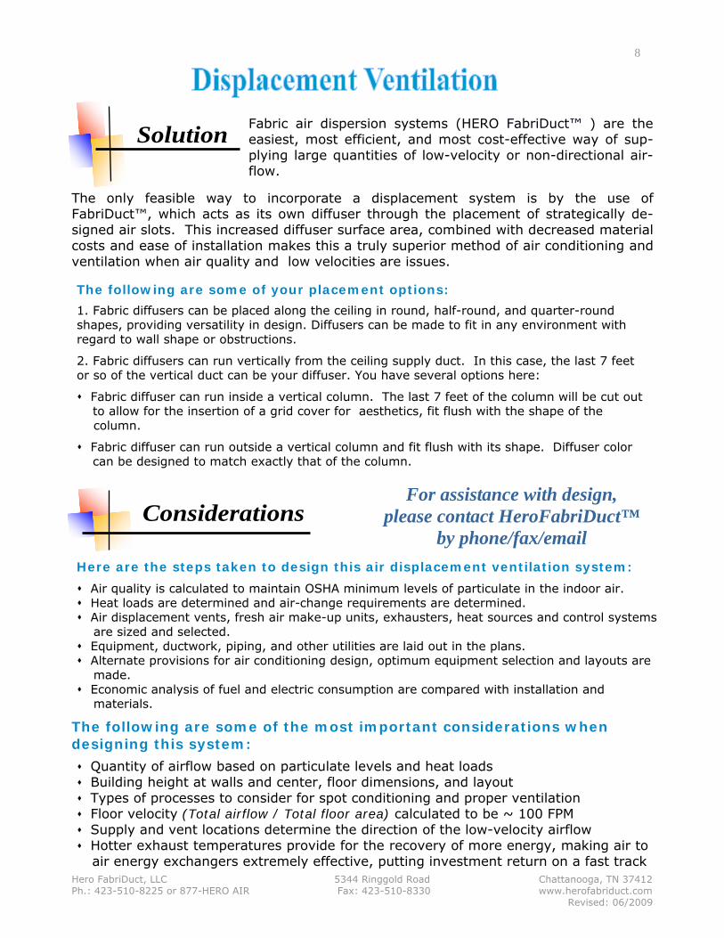
The following are some of your placement options:
1. Fabric diffusers can be placed along the ceiling in round, half-round, and quarter-round shapes, providing versatility in design. Diffusers can be made to fit in any environment with regard to wall shape or obstructions.
2. Fabric diffusers can run vertically from the ceiling supply duct. In this case, the last 7 feet or so of the vertical duct can be your diffuser. You have several options here:
Fabric diffuser can run inside a vertical column. The last 7 feet of the column will be cut out to allow for the insertion of a grid cover for aesthetics, fit flush with the shape of the
column.
Fabric diffuser can run outside a vertical column and fit flush with its shape. Diffuser color can be designed to match exactly that of the column.
For assistance with design, please contact HeroFabriDuct™
by phone/fax/email Here are the steps taken to design this air displacement ventilation system:
Quantity of airflow based on particulate levels and heat loads Building height at walls and center, floor dimensions, and layout Types of processes to consider for spot conditioning and proper ventilation Floor velocity (Total airflow / Total floor area) calculated to be ~ 100 FPM Supply and vent locations determine the direction of the low-velocity airflow Hotter exhaust temperatures provide for the recovery of more energy, making air to
air energy exchangers extremely effective, putting investment return on a fast track
8
The following are some of the most important considerations when designing this system:
The only feasible way to incorporate a displacement system is by the use of FabriDuct™, which acts as its own diffuser through the placement of strategically de-signed air slots. This increased diffuser surface area, combined with decreased material costs and ease of installation makes this a truly superior method of air conditioning and ventilation when air quality and low velocities are issues.
Considerations
Solution
Air quality is calculated to maintain OSHA minimum levels of particulate in the indoor air. Heat loads are determined and air-change requirements are determined. Air displacement vents, fresh air make-up units, exhausters, heat sources and control systems
are sized and selected. Equipment, ductwork, piping, and other utilities are laid out in the plans. Alternate provisions for air conditioning design, optimum equipment selection and layouts are
made. Economic analysis of fuel and electric consumption are compared with installation and
materials.
Fabric air dispersion systems (HERO FabriDuct™ ) are the easiest, most efficient, and most cost-effective way of sup-plying large quantities of low-velocity or non-directional air-flow.

Hero FabriDuct, LLC 5344 Ringgold Road Chattanooga, TN 37412 Ph.: 423-510-8225 or 877-HERO AIR Fax: 423-510-8330 www.herofabriduct.com Revised: 06/2009
The advantages of using Hero FabriDuct™ in a displacement ventilation system are...
Overhead (Mixing)
Underfloor Air Distribution (Mixing Displacement)
Lower Wall (Displacement)
Description Diffusers located in the ceil-ing deliver 55°F air at veloc-ity of 400-700 ft. per minute (fpm). Objective is a well mixed airspace.
Diffusers mounted in the floor deliver 65°F air at about 100-200 fpm velocity. Air pattern causes some mixing in the occupied space, but a higher temperature near the ceiling.
Diffusers mounted near the floor level deliver 65°F air and less than 75 fpm velocity. Air flow causes a thermally stratified space and verti-cal air movement towards the re-turn.
Supply conditions Normally 55°F in cooling. Typically 60°F-64°F in cooling. Some temperature rise will occur in the underfloor plenum.
Typically 63°F-68°F in cooling.
Architectural require-ments
Space above ceiling for ductwork and ceiling diffus-ers.
Minimum ceiling height of 8-9 ft. recommended. A raised access floor is used as an air plenum and for wiring and communications. Possibility to reduce floor-to-floor height slightly.
Minimum ceiling height of 9 ft. is recommended. Higher ceilings are preferred. Diffusers may take up some wall space. Floor-to-floor height is not necessarily impacted.
Thermal comfort Even temperatures through-out the space in cooling with proper design.
Good thermal comfort with proper airflow. Potential for individual temperature control.
Very good thermal comfort in cool-ing with proper design. Some potential for drafts near the diffus-ers.
Ventilation effectiveness FAIR-Supply air mixes with room air to dilute contami-nants.
GOOD-Better than overhead distribution, but some mixing occurs in the occupied zone.
VERY GOOD-Supply air is deliv-ered to occupants, and contami-nants are displaced to the upper unoccupied zone.
Acoustic performance Diffusers can be a noise source if the air velocity is too high.
Quieter due to low air velocity. Also quieter due to lower air veloc-ity at the diffusers.
Applications Any Offices or any space with open floor plans.
Schools, restaurants, theaters, atria, and other spaces with high ceilings.
Improved ventilation efficiency, resulting in better indoor air quality
• Harmful gases and particulates are eliminated from the breathing space • Air is thermally stratified from floor to ceiling so that clean air is where people need to
breathe it
• Reduced ventilation loads (quantity and temperature of supply air) means reduced fuel and electric costs
• Improved worker and occupant comfort and health in the occupied zone
Energy savings - the higher supply air temperature results in greater opportunities for use of airside economizers
Improved acoustics - the low velocity air supply should generate less noise than a typical supply diffuser
9

Hero FabriDuct, LLC 5344 Ringgold Road Chattanooga, TN 37412 Ph.: 423-510-8225 or 877-HERO AIR Fax: 423-510-8330 www.herofabriduct.com Revised: 06/2009
Design for 40 MIG Welders
Information Conventional Air Displacement Difference
Ventilation CFM Required 135,000 82,629 -52,371
Annual Fuel MBH Consumed 24, 376 12,720 -11,656
Annual Fuel Cost $127,457 $66,511 -$60,946
Installation Cost $160,000 $175,000 $15,000
Payback Time…. 1/4 years
Air Conditioning Load (TR) 511 Tons 311 Tons -200 Tons
Rotary Exchanger
Deduct for Energy Recovery -146 Tons
Remaining Chiller Load (TR) 165 Tons
Welding Facility 240’ Length X 210’ Width X 34’ Height
Supply air is thermally stratified on the floor, forcing contaminated air above the occupied environment.
MIXED AIR VS AIR DISPLACEMENT
Reduced quantity of supply air is needed.
Reduced temperature of supply air is needed.
Lower Operating Costs
Higher Productivity Results in a draft-free atmosphere for worker comfort and manufacturing process.
Higher Indoor Air Quality Clean, fresh air in the occupied zone
10

Hero FabriDuct, LLC 5344 Ringgold Road Chattanooga, TN 37412 Ph.: 423-510-8225 or 877-HERO AIR Fax: 423-510-8330 www.herofabriduct.com Revised: 06/2009
Hero FabriDuct™ products are subject to the following conditions:
1. The products shall not pass through any fire resistive assembly or partitions required to prevent the passage of smoke.
2. The products shall be used only as positive pressure air distribution components of mechanical ventilation systems.
3. The products shall be used in exposed interior locations only.
11
Hero FabriDuct™ products are Polyester fabric supply air diffusion sys-tems, operating under positive pressure. The diffusion occurs through any com-bination of permeable and non-permeable fabrics, and /or strategically designed linear slots. HERO Fabriduct™ systems are available in round, “D” shape, or quarter-round duct configuration. These systems are designed to provide uniform air distribution in commercial, industrial, public warehouse environments and homes. When tested in accordance with ASTM E-84, these Polyester fabrics have a flame spread index of less than 25, and a smoke developed index of less than 50. Hero FabriDuct™ fabric products are limited to use in systems with a maximum positive design pressure equivalent to 3.1 inches of water col-umn, a maximum operating velocity of 2,000 feet per minute, and a temperature range of 0° F to 250°F (-18°C to 121° C). Installation instructions published and provided by Hero FabriDuct™ pro-vide clear and concise instructions for efficient installation. A copy of these instructions should be available for reference at all times on the job site during installation.
Declaration of Hero FabriDuct™
PRODUCT TESTING

Hero FabriDuct, LLC 5344 Ringgold Road Chattanooga, TN 37412 Ph.: 423-510-8225 or 877-HERO AIR Fax: 423-510-8330 www.herofabriduct.com Revised: 06/2009
Code Requirements
Flame Spread / Smoke Development This page addresses the related fire code requirements for fabric duct distribution de-vices. FabriDuct™ systems are in accordance with the ASTM International fire test re-sponse standard E 84, Surface Burning Characteristics of Building Materials, as both a duct and diffuser. The National Fire Protection Association (NFPA) has concluded that the following fire codes have been met: ● NFPA 9OA-1993, "Installation of Air Conditioning and Ventilation Systems" ● NFPA 9OB-1993, "Warm Air Heating and Air Conditioning Systems" ● NFPA 255, "Standard Method of Test of Surface Burning Characteristics of Building Materials" (ref: NFPA 255-C.2.3.2) Description of requirements Flame spread/Smoke development must not exceed 25/50 rating. This rating and the ASTM E 84 test method are typical to UBC 8-1 and UL723. These requirements are also consistent with flame/smoke indices set by the Uniform Mechanical Code for the vari-ous pipe insulations, duct insulations, and other combustibles used in air handling ple-nums.
Considerations Torsion, collapse, air leakage and impact are related only to sheet metal duct, and do not apply to FabriDuct™, except for USDA and other similar applications. UL 181 men-tions fire code and torsion/collapse/impact indices, but only the fire code is relevant in our case. FabriDuct™ is “a combination flexible air duct and air diffuser for exposed-ceiling applications to be used as a positive pressure air distribution component".
12

Hero FabriDuct, LLC 5344 Ringgold Road Chattanooga, TN 37412 Ph.: 423-510-8225 or 877-HERO AIR Fax: 423-510-8330 www.herofabriduct.com Revised: 06/2009
13

Hero FabriDuct, LLC 5344 Ringgold Road Chattanooga, TN 37412 Ph.: 423-510-8225 or 877-HERO AIR Fax: 423-510-8330 www.herofabriduct.com Revised: 06/2009
14 INTRODUCTION
This report is a presentation of results of a surface flammability test on a material submitted by Hero FabriDuct™ . The test was conducted in accordance with the ASTM International fire test response standard E 84-01, Surface Burning Characteristics of Building Materials, sometimes referred to as the Steiner tunnel test. This test is applicable to exposed surfaces such as walls and ceilings. The test is conducted with the specimen in the ceiling position with the surface to be evaluated exposed face down to the ignition source. The method, which is functionally identical to NFPA No. 255 and UL No. 723, is an American National (ANSI) Standard and has been approved for use by agencies of the Department of Defense for listing in the DoD Index of Specifications and Standards. This standard is used to measure and describe the response of materials, products, or assemblies to heat and flame under controlled conditions, but does not by itself incorporate all factors required for fire-hazard or fire-risk assessment of materials, products, or assemblies under actual fire conditions.
The purpose of the test is to provide the comparative measurements of surface flame spread and smoke development of materials with that of select grade red oak and reinforced cement board under specific fire exposure conditions. The test exposes a nominal 24-foot long by 20-inch wide test specimen to a controlled air flow and flaming fire adjusted to spread the flame along the entire length of a red oak specimen in 5.50 minutes. During the 10-minute test duration, flame spread over the specimen surface and density of the resulting smoke are measured and re-corded. Test results are calculated relative to red oak, which has an arbitrary rating of 100, and reinforced cement board, which has a rating of 0. The test results are expressed as Flame Spread Index and Smoke Developed Index. The Flame Spread Index is defined in ASTM E 176 as "a number or classification indicating a comparative measure derived from observations made during the progress of the boundary of a zone of flame under defined test conditions." The Smoke Developed Index, a term specific to ASTM E 84, is defined as “a number or classification indicating a comparative measure derived from smoke obscuration data collected during the test for surface burning characteristics." There is not neces-sarily a relationship between the two measurements. The method does not provide for measurement of heat transmission through the surface tested, the effect of aggravated flame spread behavior of an assembly resulting from the proximity of combustible walls and ceilings, or classifying a material as noncombustible solely by means of a Flame Spread Index. The zero reference and other parameters critical to furnace operation are verified on the day of the test by conducting a 10-minute test using 1/4-inch thick reinforced cement board. Periodic tests using NOFMA certified 23/32-inch select grade red oak flooring provide data for the 100 reference.
PURPOSE

Hero FabriDuct, LLC 5344 Ringgold Road Chattanooga, TN 37412 Ph.: 423-510-8225 or 877-HERO AIR Fax: 423-510-8330 www.herofabriduct.com Revised: 06/2009
OBSERVATIONS
Test Specimen Flame Spread Index Smoke Developed Index
Reinforced Cement Board Red Oak Flooring
0 100
0 100
FabriDuct 5 40
15
CLASSIFICATION The Flame Spread Index and Smoke Developed Index values obtained by the ASTM E 84 test are frequently used by code officials and regulatory agencies in the acceptance of interior finish materials for various applications. The most widely accepted classification system is described in the National Fire Protection Association publication NFPA 101 Life Safety Code, where: Class A 0 - 25 Flame Spread Index 0 - 450 Smoke Developed Index Class B 26 - 75 Flame Spread Index 0 - 450 Smoke Developed Index Class C 76 - 200 Flame Spread Index 0 - 450 Smoke Developed Index Class A, B, and C correspond to Type I, II, and III respectively in other codes such as SBCCI, BOCA, and ICBO. They do not preclude a material being otherwise classified by the authority of jurisdiction.
TEST SAMPLE The test sample, selected by the client, was identified as FabriDuct™, a white polyester duct fabric. The material was conditioned to equilibrium in an atmosphere with the temperature maintained at 71 ± 2° F and the relative humidity at 50 ± 5 percent. For testing, a single 25 foot length was free laid over a 2- inch hexagonal wire mesh supported by 1/4-inch diameter steel rods spanning the ledges of the tunnel furnace at 24-inch intervals. This method of aux-iliary sample support is described in Appendix X1 of the E 84 standard, Guide to Mounting Methods, Sections X1.1.2.2 and X1.1.2.3.
Specimen ignition over the burners occurred at 0.07 minute. Surface flame spread was observed to a maximum distance of 1.16 feet beyond the zero point at 0.33 minute. The maximum temperature recorded during the test was 518° F.
TEST RESULTS The test results, calculated on the basis of observed flame propagation and the integrated area under the recorded smoke density curve, are presented below. The Flame Spread Index obtained in E 84 is rounded to the nearest number divisible by five. Smoke Developed Indices are rounded to the nearest number divisible by five unless the Index is greater than 200. In that case, the Smoke Developed Index is rounded to the nearest 50 points.

Hero FabriDuct, LLC 5344 Ringgold Road Chattanooga, TN 37412 Ph.: 423-510-8225 or 877-HERO AIR Fax: 423-510-8330 www.herofabriduct.com Revised: 06/2009
1. HVAC noise is one of the most prevalent problems in quiet environments. 2. Hero FabriDuct™ air dispersion products are made of fabrics which do not conduct noise 3. Inlet velocity is also a factor in controlling the level of sound within a FabriDuct™ system.
16
FACT: Not only does a FabriDuct™ system deliver air quietly, it helps reduce the ambient sound within an environment. The soft flexible fabric acts as a baffle along the ceiling, reducing sound by breaking up small amounts of reflective noise. The benefits of noise reduction will vary between different environments and noise frequencies.
The chart (right) is based on testing results using different vent sizes, a large variety of flow rates and inlet velocities of 125 to 4000 FPM into a 16” diameter FabriDuct™ system.
Results show that lower inlet velocities will reduce the ambient sound emitted from the system.

Hero FabriDuct, LLC 5344 Ringgold Road Chattanooga, TN 37412 Ph.: 423-510-8225 or 877-HERO AIR Fax: 423-510-8330 www.herofabriduct.com Revised: 06/2009
Hero FabriDuct™ maintains that proper sizing, spacing and orientation of our standard linear caplets achieve the necessary air dispersion performance characteristics needed in a given system. These will effectively control the low velocity, diffused or short throw patterns associated with low draft displacement ventilation systems or the high velocity, direct jet or high throw patterns associated with mixing ventilation systems or any com-bination in between without the need for directional throw nozzles.
As with any diffuser, the actual throw velocities will change based on the specific environment. To direct the expected throws, the orientation of the linear slots may be specified to better fit your application.
DUCTVENT THROW DATA
Once the Vent Size has been chosen, the airflow being released from that vent must be considered. The following graph indicates air stream velocities at set distances from the vent outlet per vent size. The throw rates here only reflect the performance at 0.5” w.g. static pressure. This information was achieved through testing in a closed-in isolated environment similar to the model shown.
6’ Graphic of testing model used to generate throw data for chart.
17
700 600 500 400 300 200 100 0
2 4 6 8 10 12 14
Throw Distance (feet)
Ven
t Thr
ow A
ir V
eloc
ity

Hero FabriDuct, LLC 5344 Ringgold Road Chattanooga, TN 37412 Ph.: 423-510-8225 or 877-HERO AIR Fax: 423-510-8330 www.herofabriduct.com Revised: 06/2009
O <
——
–—-—
——
->
<—
——
——
——
——
——
—>
\ \ \ \ \ \ \ \
Because each FabriDuct™ system is 100% custom made, there is unlimited flexibility in designing the locations of the linear slots. The orientation of the linear slots also affects the suspension system. 11 & 1, 10 & 2 AND 3 & 9 O'CLOCK
Primarily chosen for cooling or ventilating, these locations either push the exiting air upward and / or outward from the FabriDuct™. Do not concern yourself with throw requirements other than to reach the exterior walls or fill the gaps between parallel runs.
4 & 8, 5 & 7 AND 6 O'CLOCK Primarily chosen for applications with heating but can also be used for cooling or ventilating, these locations push the exiting air downward and/or outward from the FabriDuct™. Throw requirements are critical in these locations because the air is delivered towards the employees or equipment. To calculate the throw, use the distance between the bottom of the FabriDuct™ system and the distance above the floor. To calculate throw, use the following equations:
CUSTOM LINEAR SLOTS LOCATIONS AVAILABLE UPON REQUEST.
18
3
5
10
9 Orientation
from inlet of
sock
6
8
7
11
2
1
4 & 8 o'clock: (FabriDuct™ Height - 6) x 2.00 = Throw required 5 & 7 o'clock: (FabriDuct™ Height - 6) x 1.16 = Throw required 6 o'clock: (FabriDuct™ Height - 6) x 1.00 = Throw required
4

Hero FabriDuct, LLC 5344 Ringgold Road Chattanooga, TN 37412 Ph.: 423-510-8225 or 877-HERO AIR Fax: 423-510-8330 www.herofabriduct.com Revised: 06/2009
19
• AHU outlet diameter
• External Static Pressure (ESP)
• Outlet Airflow Velocity
• Room dimensions
• Suspension options
Soft Start Controls: for larger CFM (10,000 CFM or greater) FabriDuct™ recommends a frequency drive or soft start motor controller to slowly increase the speed of the fans. This will help eliminate the “popping” effect caused by the initial serge of air flow. Variable Air Volume (VAV): testing has revealed that FabriDuct™ systems are able to perform at levels 40% below and 50% above standard design. Please notify us if you plan on such requirements. Two-Speed / Staging Fans: Continuous fan duty is recommended for standard systems in order to reduce wear on the units and FabriDuct™ systems. For large, industrial and commercial installations, you may consider a fan to keep the FabriDuct™ system par-tially inflated while not in use, so that when the main fan is turned on, there is no wear on units or the FabriDuct™ system and no “popping” effect.
Design Considerations
Existing: Many units may not be able to compensate for the addi-tional static pressure needed to properly inflate the system, so booster fans and dampers may be required for the retrofit.
New: ESP must be 3/8" to 1/2" w.g. and will need lower outlet velocities at the inlet. A minimum 30% pre-filter is recommended to increase the time between cleanings.
• AHU Controls

Hero FabriDuct, LLC 5344 Ringgold Road Chattanooga, TN 37412 Ph.: 423-510-8225 or 877-HERO AIR Fax: 423-510-8330 www.herofabriduct.com Revised: 06/2009
FabriDuct™ systems are self-balancing. Normally (with sheet metal installations), CFM numbers are displayed beside registers on drawings. With FabriDuct™ systems, there are no registers as the duct is the diffuser. Therefore, balancing is based on the Deliv-ery Area (CFM per square foot of duct), which will be determined during the system design process by our qualified engineers (at no cost) or by your personnel (if/when experienced with FabriDuct™ installations).
Ex.) A 65' section of 30" Round at 30 CFM/sq. ft. This kind of specification from you will allow us to design the system to your requirements, or can be provided by us from more basic information from you at no additional cost.
Since the entire duct run is a diffuser and is fabric, SMACNA code (relating ONLY to sheet metal) does not relate to FabriDuct™ installations. Leakage is a necessary feature here! For additional information, please do not hesitate to call us at (877) HERO AIR, (423) 510-8225 or via Email at [email protected].
Design Calculations
Delivery Area Calculated as follows: Area = Diameter x 3.14 x Length (ft2)
Balancing your system
Available Fittings • Elbows: any angle / diameter can be specified within reason • Tees: Various shapes and construction options are available for inlet and connection
tees, depending upon the application's requirements. • Reducers: inlet and outlet diameter and length of reducer can be specified
Inlet Velocity: for diameter determination Suggested velocities are 1,500-2,000 FPM. Calculated as follows: (Qtotal = total airflow in CFM) Vel=Qtotal / (DIA/ 24)2 x 3.14) (FPM)
Velocity Pressure: average inlet velocity (velocity pressure is regained as static pressure since system is closed) Calculated as follows: VP = (Inlet Velocity / 4005)2 (inch H2O)
20
To ensure proper inflation: Keep static pressure at least 30% higher than the VP Recommended static pressure is 3/8” to 1/2” w.g. (water gauge)

Hero FabriDuct, LLC 5344 Ringgold Road Chattanooga, TN 37412 Ph.: 423-510-8225 or 877-HERO AIR Fax: 423-510-8330 www.herofabriduct.com Revised: 06/2009
8.1 oz POLYESTER • Air Permeability: 0 • Temperature Range: 0o F to 250o F • Fabric Construction: 100% Flame Retardant • Fire Retardancy: Meets testing requirements of fabric air dispersion systems
as defined in NFPA 90A and 90B. Our product achieves a Class 1 rating per ASTM E-84.
• Colors — available in 25 standard colors: Our most popular colors choices are Burgundy, Red, Orange, Yellow, Gold, Purple, Royal, Navy, Forest Green, Taupe, Tan, Silver, Charcoal, White and Black (Please note that reds are not an option for pool applications.)
7 oz POLYESTER • Air Permeability: 22 CFM/ft.² (+1-1) ASTM D737 • Temperature Range: 0o F to 250o F • Fabric Construction: 100% Flame Retardant • Fire Retardancy: Meets testing requirements of fabric air dispersion systems
as defined in NFPA 90A and 90B. Our product achieves a Class 1 rating per ASTM E-84.
• Color: As selected by architect. 9 oz POLYESTER • Air Permeability: 5 CFM/ft.² (+1-1) ASTM D737 • Temperature Range: 0o F to 250o F • Fabric Construction: 100% Flame Retardant • Fire Retardancy: Meets testing requirements of fabric air dispersion systems
as defined in NFPA 90A and 90B. Our product achieves a Class 1 rating per ASTM E-84.
• Color: As selected by architect.
OTHER FABRIC OPTIONS • Other fabric weights and porosities are available to meet your criteria SPECIAL FABRIC TREATMENTS • Antimicrobial • Antistatic • Please check with us if you have any additional requirements
21

Hero FabriDuct, LLC 5344 Ringgold Road Chattanooga, TN 37412 Ph.: 423-510-8225 or 877-HERO AIR Fax: 423-510-8330 www.herofabriduct.com Revised: 06/2009
The following pages 21-28 are specs for our most common fabrics.
We do have other fabrics to meet your specific requirements.
22

Hero FabriDuct, LLC 5344 Ringgold Road Chattanooga, TN 37412 Ph.: 423-510-8225 or 877-HERO AIR Fax: 423-510-8330 www.herofabriduct.com Revised: 06/2009
3. Design & Fabrication Requirements:
a. Lengths to include required zippers as specified by manufacturer. b. Inlet transition and end cap to include zippers for easy removal/maintenance c. Dispersion by Linear Slots. d. Width of and location of linear slots to be specified and approved by manufacturer. e. Fabric System to include connectors to attach to suspension system listed below. f. Inlet connection to metal duct via metal band supplied by manufacturer. g. Fabric diffusers should only be used for positive pressure air distribution components of the mechanical ventilation system. h. Fabric air diffusers shall be designed for 0.5-inch water gage, producing a maximum operating pressure of 3.1 inches of water.
1. Manufacturer for Fabric Made Ductwork: HERO FabriDuct, LLC Hero FabriDuct, LLC 5344 Ringgold Rd. Chattanooga, TN 37412 Phone: 1-877-HERO AIR FAX: 1-423-510-8330
Specifications for Hero FabriDuct™ Fabric Air Dispersion System
a. Fabric Construction: 100% Flame Retardant Polyester b. Weight: 8.1 oz c. Colors: We offer 25 standard colors. Our most popular colors choices are
Burgundy, Red, Orange, Yellow, Gold, Purple, Royal, Navy, Forest Green, Taupe, Tan, Silver, Charcoal, White and Black
d. Air Permeability: 0 e. Temperature Range: 0° F to 250° F f. Fire Retardancy: Meets testing requirements of fabric air dispersion systems
as defined in NFPA 90A & 90B. Our product achieves a Class 1 rating per ASTM E-84.
2. Air diffusers shall be constructed of a woven fire retardant fabric complying with the following physical characteristics:
23

Hero FabriDuct, LLC 5344 Ringgold Road Chattanooga, TN 37412 Ph.: 423-510-8225 or 877-HERO AIR Fax: 423-510-8330 www.herofabriduct.com Revised: 06/2009
24
i. Diffuser lengths, static pressure and design CFM shall be designed/approved by the manufacturer. j. Fabric air diffusers cannot be used in concealed locations. k. Fabric air diffusers shall be limited to design temperatures between 0° F and a maximum of 250° F. l. All deviations from a straight run shall be designed by the manufacturer to meet job specifications.
4. Suspension Hardware:
a. One & Two Row Cable: Systems shall include plastic coated cable, eyebolts,
cable clamps, thimbles, and turnbuckles. Attachment shall be made using snap clips spaced 24 inches apart. Vertical support hardware for longer and larger diameter applications is required. These supports should be installed approxi-mately every 25 feet.
b. One & Two Row Aluminum Track/Roller Tab: Hardware to include 12, 14 or 16-foot sections of track, sliders, splice connections and end caps. If suspended, vertical cable supports (max 8 foot spacing) require eyebolts and cable clamps.
c. One & Two Aluminum Track/Cord In: Same options as the Roller Tab system, but attachment to track system will be made with a continuous length sewn into the appropriate position for installation.
5. Installation, Cleaning and Protection: a. Install chosen suspension system in accordance with the requirements of the manufacturer. The product manufacturer is to provide installation instructions. b. Clean air-handling unit (s) and duct work just prior to installing fabric air diffusers. Clean external surfaces of foreign substances that might cause corrosive deterioration of facing. c. At duct ends not connected to equipment or distribution device at time of ductwork installation, cover with polyethylene film or other covering to keep system clean until installation is completed. d. If Hero FabriDuct™ air diffuser system becomes soiled during installation, remove and clean in accordance with manufacturer’s standard terms of laundry. e. Hero FabriDuct™ has been tested and meets the requirements of ASTM E 84 as an Air Distribution Device. The products also meet the requirements set by the NFPA 90A and 90B compliance: Class 1 rating per NFPA 255. f. Hero FabriDuct™ products shall be 100% warranted to be free from manufacturing defects for one year from date of shipment; prorated for 9 years thereafter.

Hero FabriDuct, LLC 5344 Ringgold Road Chattanooga, TN 37412 Ph.: 423-510-8225 or 877-HERO AIR Fax: 423-510-8330 www.herofabriduct.com Revised: 06/2009
1. Manufacturer for Fabric Made Ductwork: HERO FabriDuct, LLC Hero FabriDuct, LLC 5344 Ringgold Rd. Chattanooga, TN 37412 Phone: 1-877-HERO AIR FAX: 1-423-510-8330 2. Air diffusers shall be constructed of a woven fire retardant fabric complying with the following physical characteristics:
a. Fabric Construction: 100% Flame Retardant Polyester b. Weight: 7 oz c. Color: As selected by architect d. Air Permeability: 22 CFM/ft.² (+1-1) ASTM D737 e. Temperature Range: 0° F to 250° F f. Fire Retardancy: Meets testing requirements of fabric air dispersion systems
as defined in NFPA 90A & 90B. Our product achieves a Class 1 rating per ASTM E-84.
3. Design & Fabrication Requirements:
a. Lengths to include required zippers as specified by manufacturer. b. Inlet transition and end cap to include zippers for easy removal/maintenance. c. Dispersion by Linear Slots. d. Width of and location of linear slots to be specified and approved by manufacturer. e. Fabric System to include connectors to attach to suspension system listed below. f. Inlet connection to metal duct via metal band supplied by manufacturer. g. Fabric diffusers should only be used for positive pressure air distribution components of the mechanical ventilation system. h. Fabric air diffusers shall be designed for 0.5-inch water gage, producing a maximum operating pressure of 3.1 inches of water.
Specifications for Hero FabriDuct™ Fabric Air Dispersion System
25

Hero FabriDuct, LLC 5344 Ringgold Road Chattanooga, TN 37412 Ph.: 423-510-8225 or 877-HERO AIR Fax: 423-510-8330 www.herofabriduct.com Revised: 06/2009
26
i. Diffuser lengths, static pressure and design CFM shall be designed/approved by the manufacturer. j. Fabric air diffusers cannot be used in concealed locations. k. Fabric air diffusers shall be limited to design temperatures between 0° F and a maximum of 250° F. l. All deviations from a straight run shall be designed by the manufacturer to meet job specifications.
4. Suspension Hardware:
a. One & Two Row Cable: Systems shall include plastic coated cable, eyebolts,
cable clamps, thimbles, and turnbuckles. Attachment shall be made using snap clips spaced 24 inches apart. Vertical support hardware for longer and larger diameter applications is required. These supports should be installed approxi-mately every 25 feet.
b. One & Two Row Aluminum Track/Roller Tab: Hardware to include 12, 14 or 16-foot sections of track, sliders, splice connections and end caps. If suspended, vertical cable supports (max 8 foot spacing) require eyebolts and cable clamps.
c. One & Two Aluminum Track/Cord In: Same options as the Roller Tab system, but attachment to track system will be made with a continuous length sewn into the appropriate position for installation.
5. Installation, Cleaning and Protection: a. Install chosen suspension system in accordance with the requirements of the manufacturer. The product manufacturer is to provide installation instructions. b. Clean air-handling unit (s) and duct work just prior to installing fabric air diffusers. Clean external surfaces of foreign substances that might cause corrosive deterioration of facing. c. At duct ends not connected to equipment or distribution device at time of ductwork installation, cover with polyethylene film or other covering to keep system clean until installation is completed. d. If Hero FabriDuct™ air diffuser system becomes soiled during installation, remove and clean in accordance with manufacturer’s standard terms of laundry. e. Hero FabriDuct™ has been tested and meets the requirements of ASTM E 84 as an Air Distribution Device. The products also meet the requirements set by the NFPA 90A and 90B compliance: Class 1 rating per NFPA 255. f. Hero FabriDuct™ products shall be 100% warranted to be free from manufacturing defects for one year from date of shipment; prorated for 9 years thereafter.

Hero FabriDuct, LLC 5344 Ringgold Road Chattanooga, TN 37412 Ph.: 423-510-8225 or 877-HERO AIR Fax: 423-510-8330 www.herofabriduct.com Revised: 06/2009
1. Manufacturer for Fabric Made Ductwork: HERO FabriDuct, LLC Hero FabriDuct, LLC 5344 Ringgold Rd. Chattanooga, TN 37412 Phone: 1-877-HERO AIR FAX: 1-423-510-8330
Specifications for Hero FabriDuct™ Fabric Air Dispersion System
3. Design & Fabrication Requirements:
a. Lengths to include required zippers as specified by manufacturer. b. Inlet transition and end cap to include zippers for easy removal/maintenance. c. Dispersion by Linear Slots. d. Width of and location of linear slots to be specified and approved by manufacturer. e. Fabric System to include connectors to attach to suspension system listed below. f. Inlet connection to metal duct via metal band supplied by manufacturer. g. Fabric diffusers should only be used for positive pressure air distribution components of the mechanical ventilation system. h. Fabric air diffusers shall be designed for 0.5-inch water gage, producing a maximum operating pressure of 3.1 inches of water.
2. Air diffusers shall be constructed of a woven fire retardant fabric complying with the following physical characteristics:
a. Fabric Construction: 100% Flame Retardant Polyester b. Weight: 9 oz c. Color: As selected by architect. d. Air Permeability: 5 CFM/ft.² (+1-1) ASTM D737 e. Temperature Range: 0° F to 250° F f. Fire Retardancy: Meets testing requirements of fabric air dispersion systems
as defined in NFPA 90A & 90B. Our product achieves a Class 1 rating per ASTM E-84.
27

Hero FabriDuct, LLC 5344 Ringgold Road Chattanooga, TN 37412 Ph.: 423-510-8225 or 877-HERO AIR Fax: 423-510-8330 www.herofabriduct.com Revised: 06/2009
28
i. Diffuser lengths, static pressure and design CFM shall be designed/approved by the manufacturer. j. Fabric air diffusers cannot be used in concealed locations. k. Fabric air diffusers shall be limited to design temperatures between 0° F and a maximum of 250° F. l. All deviations from a straight run shall be designed by the manufacturer to meet job specifications.
4. Suspension Hardware:
a. One & Two Row Cable: Systems shall include plastic coated cable, eyebolts,
cable clamps, thimbles, and turnbuckles. Attachment shall be made using snap clips spaced 24 inches apart. Vertical support hardware for longer and larger diameter applications is required. These supports should be installed approxi-mately every 25 feet.
b. One & Two Row Aluminum Track/Roller Tab: Hardware to include 12, 14 or 16-foot sections of track, sliders, splice connections and end caps. If suspended, vertical cable supports (max 8 foot spacing) require eyebolts and cable clamps.
c. One & Two Aluminum Track/Cord In: Same options as the Roller Tab system, but attachment to track system will be made with a continuous length sewn into the appropriate position for installation.
5. Installation, Cleaning and Protection: a. Install chosen suspension system in accordance with the requirements of the manufacturer. The product manufacturer is to provide installation instructions. b. Clean air-handling unit (s) and duct work just prior to installing fabric air diffusers. Clean external surfaces of foreign substances that might cause corrosive deterioration of facing. c. At duct ends not connected to equipment or distribution device at time of ductwork installation, cover with polyethylene film or other covering to keep system clean until installation is completed. d. If Hero FabriDuct™ air diffuser system becomes soiled during installation, remove and clean in accordance with manufacturer’s standard terms of laundry. e. Hero FabriDuct™ has been tested and meets the requirements of ASTM E 84 as an Air Distribution Device. The products also meet the requirements set by the NFPA 90A and 90B compliance: Class 1 rating per NFPA 255. f. Hero FabriDuct™ products shall be 100% warranted to be free from manufacturing defects for one year from date of shipment; prorated for 9 years thereafter.

Hero FabriDuct, LLC 5344 Ringgold Road Chattanooga, TN 37412 Ph.: 423-510-8225 or 877-HERO AIR Fax: 423-510-8330 www.herofabriduct.com Revised: 06/2009
HERO FabriDuct™ is proud to offer 25 standard colors. Represented below are our most popular color choices. FabriDuct™ can also be screen printed with the end user’s logo for a nominal fee.
FOREST PURPLE ROYAL NAVY
BLACK SILVER CHARCOAL WHITE
GOLD YELLOW
TAN
RED ORANGE BURGUNDY
TAUPE
29

Hero FabriDuct, LLC 5344 Ringgold Road Chattanooga, TN 37412 Ph.: 423-510-8225 or 877-HERO AIR Fax: 423-510-8330 www.herofabriduct.com Revised: 06/2009
30
Hero FabriDuct, LLC 5344 Ringgold Road Chattanooga, TN 37412 Ph.: 423-510-8225 or 877-HERO AIR Fax: 423-510-8330 www.herofabriduct.com Revised: 06/2009
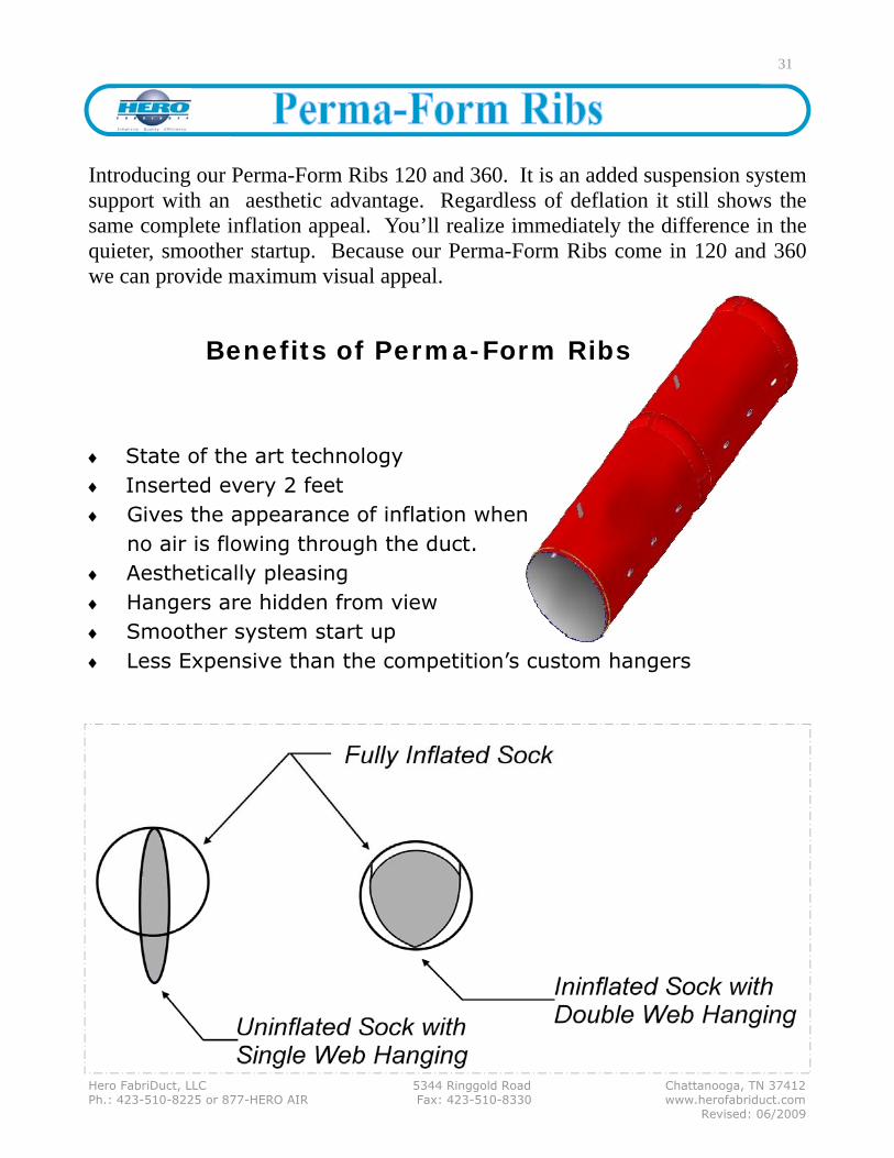
♦ State of the art technology ♦ Inserted every 2 feet ♦ Gives the appearance of inflation when
no air is flowing through the duct. ♦ Aesthetically pleasing ♦ Hangers are hidden from view ♦ Smoother system start up ♦ Less Expensive than the competition’s custom hangers
Benefits of Perma-Form Ribs
Introducing our Perma-Form Ribs 120 and 360. It is an added suspension system support with an aesthetic advantage. Regardless of deflation it still shows the same complete inflation appeal. You’ll realize immediately the difference in the quieter, smoother startup. Because our Perma-Form Ribs come in 120 and 360 we can provide maximum visual appeal.
31

Hero FabriDuct, LLC 5344 Ringgold Road Chattanooga, TN 37412 Ph.: 423-510-8225 or 877-HERO AIR Fax: 423-510-8330 www.herofabriduct.com Revised: 06/2009
OPTION: CABLE
Detail—assembly at “L” brace or wall
Cable is installed using a system incorporating eyebolts and turn-buckles attached to “L” braces or walls to carry the FabriDuct™ across the space horizontally. For lengths over 50 feet cabling should also be hung vertically and attached to the horizontal cable every 25 feet, keeping the system level.
Single cable is appropriate for FabriDuct™ diameters up to 24 inches. Double cable is highly rec-ommended for applications where the FabriDuct™ diameter is 24 inches or larger.
RECOMMENDATION
32
Detail—verticals and zippers

Hero FabriDuct, LLC 5344 Ringgold Road Chattanooga, TN 37412 Ph.: 423-510-8225 or 877-HERO AIR Fax: 423-510-8330 www.herofabriduct.com Revised: 06/2009
Single track is appropriate for FabriDuct™ diameters up to 24 inches. Double track is highly recommended for applications where the FabriDuct™ diameter is 24 inches or larger.
Cord-In Flush-mount track aluminum rail
Cord-In Suspended track aluminum rail
Aluminum track can be mounted two ways: flush-mounted to the ceiling (diag. 1 and 4) or suspended from the ceiling using hanger supports every 5 feet along the length of the track (diag. 2 and 3). Which method to use is strictly dependent on architectural necessity, such as a low ceiling, or aesthetic preference.
FabriDuct™ can be hung from the track using either of two methods. The FabriDuct™ can be constructed with a cord-in feature (diag. 1 and 2) which slides into the track providing a continuous con-nection, or by using a series of clips (diag. 3 and 4) positioned every two feet along the length of the FabriDuct™.
Flush-mount track aluminum rail clip option
HANGING OPTIONS
OPTION: ALUMINUM TRACK
RECOMMENDATIONS:
33
Suspended track aluminum rail clip option
Clamp End Stop
Coated Cable & Rope Clip
Splice
Slide
Aluminum Track

Hero FabriDuct, LLC 5344 Ringgold Road Chattanooga, TN 37412 Ph.: 423-510-8225 or 877-HERO AIR Fax: 423-510-8330 www.herofabriduct.com Revised: 06/2009
SINGLE AND DOUBLE CABLE SUPPORT SYSTEM
34
The support cable runs the entire length of the duct and extends to each wall, or drop down angle support, where it is connected via eyebolts and turnbuckles. Additional support for runs in excess of 25 feet will be provided by installing vertical support cables every 25 feet along the length of the support cable and connected to it via the supplied connectors.
“T” with Single Cable
90° with Double Cable
“T” with Double Cable
Example of Double Cable Installation
Verticals

Hero FabriDuct, LLC 5344 Ringgold Road Chattanooga, TN 37412 Ph.: 423-510-8225 or 877-HERO AIR Fax: 423-510-8330 www.herofabriduct.com Revised: 06/2009
Suspension Systems Man Hours to install the suspension system and attach FabriDuct™ sections together. Cable - Horizontals 2 hours for each straight section plus ½ hour for each 25 feet of length.
Cable - Verticals ¼ hour for each vertical.
Track - flush mount 2 hours for each straight section plus 1 hour for each 25 feet of length.
Track- hanging 2 hours for each straight section plus ½ hour for each 25 feet of length. length. Inlet Diameter Man Hours to connect FabriDuct™ transition to inlet: 8 inch to 24 inch ½ hour 25 inch to 40 inch ¾ hour 41 inch to 60 inch 1 hour
35
This Hero FabriDuct™ installation estimator is to be used as a helpful guide for contractors to determine labor cost to install Hero FabriDuct™.
4) The times above are based on: (a) experienced FabriDuct™ installers, (b) at least two man crews, (c) ceiling heights of less than 30 feet with no obstructions, and (d) since every job is different, times have not been calculated for manufacturing and installing drop "L" braces.
1) Installation of Hero FabriDuct™ has very little in common with metal duct when estimating installation times and costs. The use of fabric simplifies the entire installation process due to its unique characteristics and its light weight. By using zippered sections and cable or track suspension systems, in-stallation time is kept to a minimum.
2) FabriDuct™’s above mentioned characteristics as well as inlet attach-ment requirements, diameters, fittings, number of runs and length of straight continuous sections all affect labor cost.
3) The following charts represent time frames that can be used to calculate the majority of Hero FabriDuct™ installations. These times represent estimates for installing the inlet section, suspension system, connecting zippered sections and fittings together. Note: Each horizontal plane change is calculated separately. Times are based on single row cable or track; you will need to multiply time by 2 if using double cable or track systems. For 25-inch to 40-inch diameters add 10% and 41-inch to 60-inch diameters add 20% to the Suspension system times. For our D-Shape and Quarter Round systems use the flush mount requirements and multiply time by 2.

Hero FabriDuct, LLC 5344 Ringgold Road Chattanooga, TN 37412 Ph.: 423-510-8225 or 877-HERO AIR Fax: 423-510-8330 www.herofabriduct.com Revised: 06/2009
36
When requesting a quote from Hero FabriDuct™, please provide the following information:
Requests for quotes may be sent via fax (423-510-8330) or email ([email protected]). For additional information please call: 877-HERO AIR (877-437-6247) or 423-510-8225.
1. The CFM of the unit, as well as the CFM of each run.
2. Room dimensions
3. A drawing or sketch of the desired system, including the number of runs, length of runs, and any elbows, “Ts”, or “Ys” and their location.
4. The suspension system requested (cable or track) .
5. General use of the area (pool, gym, industrial, chemical, etc.)
6. Job name
7. Your business name, physical address & type of business (contractor, distributor, representative, etc.).
8. Contact name, phone number, fax number, and email address

Hero FabriDuct, LLC 5344 Ringgold Road Chattanooga, TN 37412 Ph.: 423-510-8225 or 877-HERO AIR Fax: 423-510-8330 www.herofabriduct.com Revised: 06/2009
These are the instructions for the installation of FabriDuct™ standard ventilation Draft-Free, air distribution FabriDuct™ woven fabric combined duct and outlet. Inspect shipment carefully matching contents with packing slip information. Account for everything. Note any missing or damaged pieces listed on the Bill of Lading before accepting the shipment in order to facilitate a claim for shipping damage with carrier or UPS.
1. INSTALLING ROUND DUCT ON HORIZONTAL CABLE
37
1. Suspend horizontal cable(s), per detailed instructions, at desired height with turnbuckles and lock nuts…pull cable taut. 2. Mount the FabriDuct™ to the cable using the clips on the FabriDuct™. 3. Attach Vertical Risers to ceiling overhead anchors approximately every
25 feet along the run and fasten the Vertical Risers to the cable to maintain the cable straight and level.
4. Attach FabriDuct™ collar to the distribution system sheet metal transition (See page 40).
For diameters of 24” or larger, installation of *two rows of cable will usually be required, one on each side of the centerline of the FabriDuct™. In some instances it may be desirable to install a lock nut to the cable be-fore the last clip to hold the FabriDuct™ fully extended.
Turnbuckle Attaches between building anchor and suspension cable and is used to tighten cable.
Wire-lock nut Used to clamp cable to turnbuckles or building anchor.
Vertical Riser Attaches to building structure to support suspension cable.
Hero FabriDuct, LLC 5344 Ringgold Road Chattanooga, TN 37412 Ph.: 423-510-8225 or 877-HERO AIR Fax: 423-510-8330 www.herofabriduct.com Revised: 06/2009
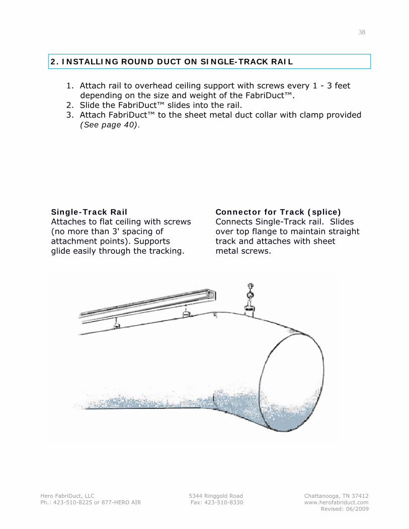
Connector for Track (splice) Connects Single-Track rail. Slides over top flange to maintain straight track and attaches with sheet metal screws.
Single-Track Rail Attaches to flat ceiling with screws (no more than 3' spacing of attachment points). Supports glide easily through the tracking.
1. Attach rail to overhead ceiling support with screws every 1 - 3 feet depending on the size and weight of the FabriDuct™. 2. Slide the FabriDuct™ slides into the rail. 3. Attach FabriDuct™ to the sheet metal duct collar with clamp provided (See page 40).
2. INSTALLING ROUND DUCT ON SINGLE-TRACK RAIL
38

Hero FabriDuct, LLC 5344 Ringgold Road Chattanooga, TN 37412 Ph.: 423-510-8225 or 877-HERO AIR Fax: 423-510-8330 www.herofabriduct.com Revised: 06/2009
3. INSTALLING ROUND DUCT USING A SUSPENDED TRACK RAIL
1. Anchor one end of the Vertical Riser to ceiling overhead every 5 feet, including a Vertical Riser at each end of the run.
2. Attach Splices onto the track at appropriate intervals to join and straighten multiple rail sections.
3. Adjust Vertical Risers individually to level and straighten the entire length of track rail.
4. Slide the FabriDuct™ sliders into the track of the rail. Attach the FabriDuct™ clips to the gliders. When using cord-in method, slide the cord into the track rail.
5. Attach the FabriDuct™ inlet to the sheet metal duct collar with clamp(s) provided (See page 40).
For diameters 24” or larger, installation of *two Single-Track rails will be required, one on each side of the centerline of the FabriDuct™ (double track).
39
End-cap (Stop) Gives finished look to track rail and provides an end stop.
Vertical Riser Attaches to building structure to support track rail. They can be ordered to specific lengths.
Suspended Track Rigid suspension track for round FabriDuct™. Vertical cable risers attach by clamps, FabriDuct™ by slides in rail or cord-in.
Hero FabriDuct, LLC 5344 Ringgold Road Chattanooga, TN 37412 Ph.: 423-510-8225 or 877-HERO AIR Fax: 423-510-8330 www.herofabriduct.com Revised: 06/2009
5. INSTALLING QUARTER ROUND DUCT ONTO DOUBLE TRACK RAILS
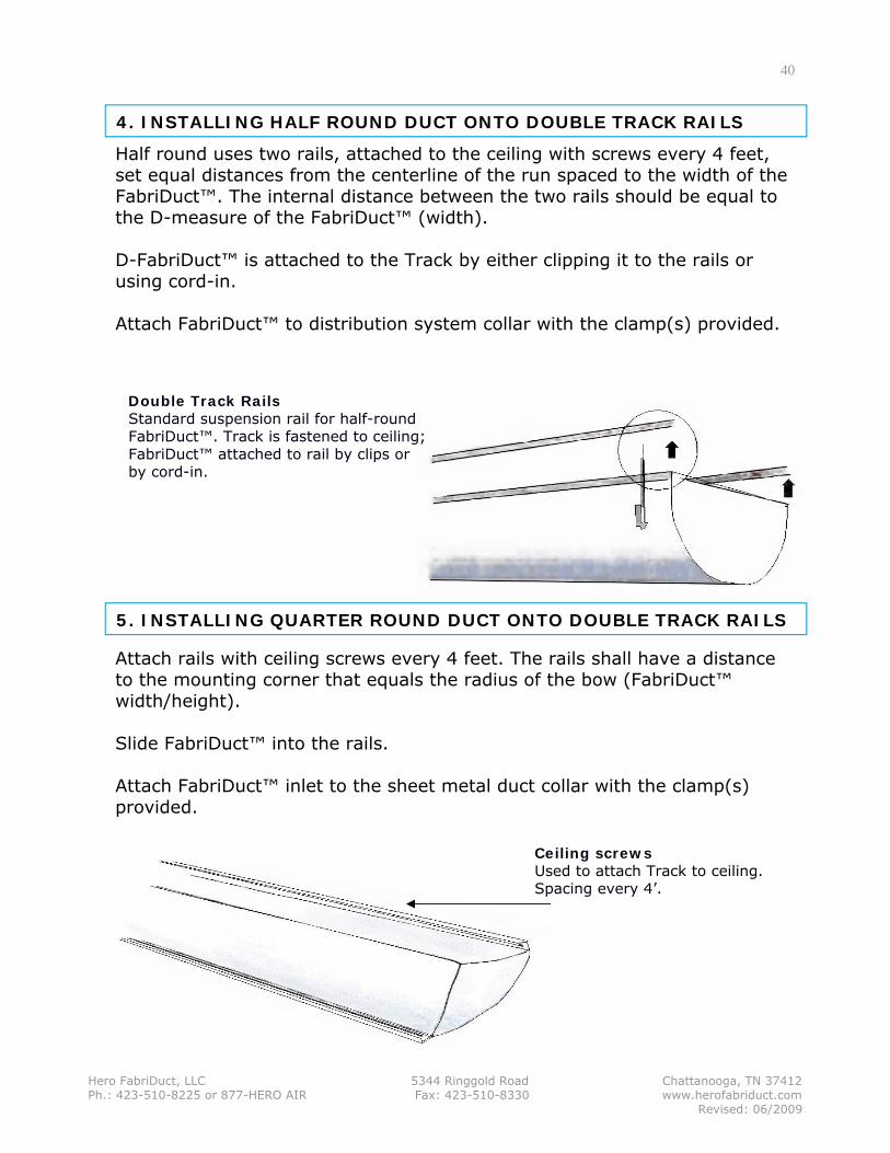
Half round uses two rails, attached to the ceiling with screws every 4 feet, set equal distances from the centerline of the run spaced to the width of the FabriDuct™. The internal distance between the two rails should be equal to the D-measure of the FabriDuct™ (width). D-FabriDuct™ is attached to the Track by either clipping it to the rails or using cord-in. Attach FabriDuct™ to distribution system collar with the clamp(s) provided.
4. INSTALLING HALF ROUND DUCT ONTO DOUBLE TRACK RAILS
40
Attach rails with ceiling screws every 4 feet. The rails shall have a distance to the mounting corner that equals the radius of the bow (FabriDuct™ width/height). Slide FabriDuct™ into the rails. Attach FabriDuct™ inlet to the sheet metal duct collar with the clamp(s) provided.
Double Track Rails Standard suspension rail for half-round FabriDuct™. Track is fastened to ceiling; FabriDuct™ attached to rail by clips or by cord-in.
Ceiling screws Used to attach Track to ceiling. Spacing every 4’.

Hero FabriDuct, LLC 5344 Ringgold Road Chattanooga, TN 37412 Ph.: 423-510-8225 or 877-HERO AIR Fax: 423-510-8330 www.herofabriduct.com Revised: 06/2009
The Outer Cover pulls over inner lining (after the metal clamp has been secured) and completely conceals the clamp and the inner liner.
The inner liner fixes firmly over the metal. The metal clamp secures this lining.
Handle the cloth sections with clean hands. Insure that all installation tools are also clean and free of oil or dirt
1. WASH YOUR HANDS!
2. Follow the appropriate Cable or Track Assembly instructions.
3. Install the Transition Piece (with inner liner/rope hem end) by mounting it to the metal air outlet duct or plenum. DO NOT attach the Anchor Clamp at this time.
4. Install each section of the FabriDuct cloth duct to the wire cable(s) with the webbed Snap Clips. Begin with sec-tion #2 and continue in sequential order, referencing the layout diagram.
5. When all sections have been attached to the cable(s) in the proper order, the duct sections may then be connected to each other at their zipper joints. This is the best accomplished by starting at either the top seam or one of the two side seams where the snap clips are attached to the duct. Smooth out any bumps or wrinkles as you work around the circumference to connect the entire joint.
6. Secure the inner liner (with the rope hem) of the transition piece to the metal output duct with metal clamp(s). Pull the outer cover over the inner lining which is secured by the metal clamp, so that it is hidden.
7. Further adjustment to the vertical support cables (where applicable) may need to be done. Ensure that there are no sags along the duct length or the horizontal support cables. The installation is now complete.
The zipper is connected on the inside lining at the rear of the Transition and attaches to the FabriDuct sock.
Handle the cloth sections with clean hands. Insure that all installa-tion tools are also clean and free of oil or dirt.
41

Hero FabriDuct, LLC 5344 Ringgold Road Chattanooga, TN 37412 Ph.: 423-510-8225 or 877-HERO AIR Fax: 423-510-8330 www.herofabriduct.com Revised: 06/2009
1. WASH YOUR HANDS!
2. Remove Perma Form 120/Perma Form 360 from container, taking care to keep them from becoming contaminated.
3. Open the end of the Perma Form 120/Perma Form 360 Sleeve and insert one Perma Form 120/Perma Form 360 Rib.
4. Push the Rib until it stops.
5. Pull the Perma Form Flap back over the opening to seal it shut.
6. Follow the Transition Cover installation procedure (see page 40).
Handle the cloth duct sections with clean hands.
Insure that all installation tools are also clean and free of oil and dirt.
42

Hero FabriDuct, LLC 5344 Ringgold Road Chattanooga, TN 37412 Ph.: 423-510-8225 or 877-HERO AIR Fax: 423-510-8330 www.herofabriduct.com Revised: 06/2009
Washing and Storage Instructions For Hero FabriDuct™ Polyester Ducts with or without Vents
In order to ensure long term and optimum distribution of air, it is neces-sary to keep the FabriDuct™ fabric ducts free from dirt and dust. Effective maintenance will ensure that the ducts supply the required quantity of air. This will also guarantee optimum life of the ducts.
Hero FabriDuct™ provides a first class microbiological filter, the ducts are fabri-cated from polyester, which does not support bacterial growth. As a final filter, just one pass through the FabriDuct™ duct can retain 60% of particles greater than 1 micron. Because of this ability to filter, HERO FabriDuct™ highly recom-mends the use of an 85% effective pre-filter to prevent excessive cleaning maintenance. The ducts are recommended washed 1 to 2 times per year when using 85% pre-filter. When washing the fabric ducts with this interval, the white fabric may take on a grayish color. This graying appearance can be reduced by increasing washing intensity, washing frequency or by originally specifying a custom dyed fabric. Bleaching is to be avoided as it weakens the duct fiber and shortens the life of the fabric.
Before laundering, remove all Perma-Form Ribs (if applicable) and turn each duct sec-tion INSIDE OUT
- Pre-rinse 70○F for 3 minutes. * - Pre-wash 104○F for 10 minutes. * - Wash 104○F for 20 minutes. *
• *Follow detergent manufacturer quantity recommendation • Rinse thoroughly after each washing.
- Do NOT add any softener, as this will influence the surface characteristics of the FabriDuct™ duct. - Wash, spin-dry, and immediately install the FabriDuct™ ducts if possible. - Otherwise, the FabriDuct™ ducts may tumble dry with a MAXIMUM hot air temperature of 110F. - OBSERVE TO INSTALL THE DUCTS IN THE CORRECT SEQUENTIAL ORDER.
FABRIDUCT™ CLOTH DUCT STORAGE The FabriDuct™ cloth duct sections must be COMPLETELY DRY before folding for storage. The ducts must be stored in a DRY ROOM.
WASHING INSTRUCTIONS
43

Hero FabriDuct, LLC 5344 Ringgold Road Chattanooga, TN 37412 Ph.: 423-510-8225 or 877-HERO AIR Fax: 423-510-8330 www.herofabriduct.com Revised: 06/2009
Q: How does FabriDuct™ compare to Metal ductwork? A: FabriDuct™ is much lighter in weight than metal duct, resulting in a lighter roof load. It has a better appearance, and is quickly and easily installed with a minimum of manpower and equipment. Q: Is FabriDuct™ more expensive than metal ductwork? A: FabriDuct™ results in cost savings of as much as 80% when compared to metal. Q: How long can I expect FabriDuct™ to last? A: Given proper installation, care and maintenance, FabriDuct™ can be expected to last for 25 years or longer. Q: Will FabriDuct™ absorb water? A: FabriDuct™ is constructed of Polyester fabric which is formulated not to ab-
sorb water. Q: Will fabric construction allow accumulation of particulate matter on the exterior of the ductwork? A: All ductwork, regardless of type of construction will allow some accumulation of particulate matter on the exterior. Testing, as well as practical experience shows that neither the porous or non-porous version of FabriDuct™ allows any more accumulation than other types of ductwork. Q: Most systems I’ve been associated with create a lot of noise when running. Is it the same with FabriDuct™? A: The very nature of fabric is to absorb, rather than to create, transport or intensify sound. FabriDuct™ will consistently serve to baffle sounds within the system, and will result in a quieter operation overall. Q: Is FabriDuct™ limited to one color? A: Absolutely not. There are 25 attractive colors available to coordinate aesthetically with every décor.
44
Hero FabriDuct, LLC 5344 Ringgold Road Chattanooga, TN 37412 Ph.: 423-510-8225 or 877-HERO AIR Fax: 423-510-8330 www.herofabriduct.com Revised: 06/2009
Q: Does FabriDuct™ produce “popping” upon start up? A: Very seldom does “popping” occur. In the interest of eliminating this possibility on start up, we strongly recommend STAGING the start up of the unit. Q: It has been suggested that fabric might not be equal to metal in the ability to distribute air over a large area. Is it possible to cover as much area with fabric as with metal duct? A: Not only is it possible, it is standard with FabriDuct™. Linear slots, strategically placed along the length of the duct result in a marked improvement over metal, as the slots will create an even flow of air in both directions. This produces a comfortable atmosphere with no hot or cold spots. Q: Can FabriDuct™ be cleaned? A: Yes. One of the attractive features of FabriDuct™ is that is it can be taken down in a short period of time, washed in a commercial washing machine, Re-hung and be back in operation within the same day. (see Cat. Pg. 43) Q: Is there any warranty on FabriDuct? A: The standard 10 year warranty on FabriDuct™ consists of 100% coverage for the first year, prorated thereafter. Q: Does FabriDuct™ meet the requirements set forth in UL standards? A: Yes. FabriDuct™ is manufactured of materials which conform to ASTM E84, (An ANSI Standard) which is the standard that UL 723 is required to meet. Q: Will FabriDuct™ allow condensation? A: Because of being exposed, in an open conditioned space, to date, there
have been no reports of FabriDuct™ either producing or allowing any con-densation.
45

Hero FabriDuct, LLC 5344 Ringgold Road Chattanooga, TN 37412 Ph.: 423-510-8225 or 877-HERO AIR Fax: 423-510-8330 www.herofabriduct.com Revised: 06/2009
10 Year Warranty The Hero FabriDuct™ standard 10 year replacement warranty is as Follows:
• 100% coverage for the first year • Prorated from 90% - 0% over the remaining warranty period
The Hero FabriDuct™ warranty is for replacement credit based on the period remaining of the applicable stated warranty. Coverage begins at time of shipment. The covered party must make up the difference between the available warranty credit applied and the Hero selling price to repair or replace. The warranty is not available in the form of a cash payment. The warranty covers materials, fabrication and performance of the fabric portion of the FabriDuct™ system only. This warranty also requires that the original system be designed within requirements based on manufacturer’s specifications including double row suspension systems for diameters of 24” and larger and that maintenance has been performed based on manufacturer’s recommendations.
Warranty excludes damage to fabric from improper installation, poor maintenance, abuse, abrasion, caustic chemicals, exposure to high tem-perature (over 250° F), discoloration and shrinkage or any unauthorized modification to system. Costs incurred in the execution of the war-ranty, such as labor, equipment rental or freight charges will not be covered. executing the warranty.
46