for teaching purposes - murdoch research...
TRANSCRIPT

P a g e | 1
MURDOCH UNIVERSITY
Siemens Profibus System For Teaching Purposes
A report submitted to the school of Engineering and Information Technology, in partial fulfilment of
the requirements for the degree of Bachelor of Engineering.
Jonty Martens
4 February 2013

P a g e | i
Executive summary
Throughout the Industrial Computer Systems Engineering course students have only been exposed
to SCADA and industrial communications through research and limited practical applications. The
Siemens WinCC and Profibus SCADA System described in this report changes that by giving students
the opportunity to design and build their own SCADA system from scratch or build on the existing
system by incorporating new features and design aspects.
During this project, the Profibus network designed by the ENG454 students was installed in the
Industrial Computer Systems Engineering (ICSE)laboratory. This network incorporates the three sub-
network configurations designed by Brenton Walker to provide variations in server, client, and
Profibus device configuration. Utilising the documentation developed by Brenton Walker, full scale
Profibus data exchange examples have been implemented spanning more than one Single Network.

P a g e | ii
Acknowledgements
For their assistance in this project, acknowledgements are given to the following individuals:
Project Supervisor: Dr Gareth Lee
Senior Lecturer, Murdoch University
Associate Professor Graeme R Cole Associate Professor, Murdoch University
Mr Will Stirling
Technical Officer, Murdoch University
Mr John Boulton Technical Officer, Murdoch University
Mr Iafeta ‘Jeff’ Laava
Technical Officer, Murdoch University
Mr Luke Beumont Barrett Chief Design Replicator

P a g e | iii
Terminology and acronyms
Active Termination: Is a term used to describe a type of termination that requires live voltage to
correctly terminate the signal.
Fieldbus: is the generic term given to industrial communication protocols. Fieldbus networks are
typically used to connect instruments and devices to the control system in industrial plants.
GSD: Stands for General Station Description. They contain the characteristics of the device, and are
provided by the device manufacturer.
HMI: Human Machine Interface.
ICSE: Industrial Computer Systems Engineering.
ICSE lab: The room containing the equipment required to construct the Profibus system. Located in
the Physical Science building, room number 2.027 (PS2.027).
Master: The master is a device on the network that is responsible for the communication between
the slave devices. The master also acts as the control unit for the network.
Node: Throughout this document the term node will be used to describe an addressable device
(Profibus devices) connected to the network.
PLC: A Programmable Logic Controller (PLC) is a device used to carry out logical operations required
from a control point of view.
Poll: The act of a master device fetching information from a slave device.
SCADA: Supervisory Data Acquisition and Control.
Slave: A slave is a passive device that reads process information and/or transfers out putdata over
the network. Slaves can only respond when requested by a master.
VSD: Variable Speed Drive.
P a g e | iv
Contents
Executive summary .................................................................................................................................. i
Acknowledgements ................................................................................................................................. ii
Terminology and acronyms.................................................................................................................... iii
List of figures .......................................................................................................................................... ix
List of tables ........................................................................................................................................... xi
1.1 Introduction ...................................................................................................................................... 1
1.2Project scope ...................................................................................................................................... 1
1.2.1 Justification ................................................................................................................................ 1
1.2.2 Objectives................................................................................................................................... 1
1.2.4 Product scope description ......................................................................................................... 2
1.2.5 Product acceptance criteria ....................................................................................................... 2
1.2.6 Constraints ................................................................................................................................. 2
1.3Project Objectives .............................................................................................................................. 3
1.3.1 Panel layout ............................................................................................................................... 3
1.3.2 New Windows 7 computers ....................................................................................................... 3
1.3.3 SEW VSDs ................................................................................................................................... 3
1.3.4 Installation of the Profibus network .......................................................................................... 3
1.3.5 WinCC SCADA development ...................................................................................................... 3
1.3.6 Instruction manuals ................................................................................................................... 3
1.3.7 Laboratory guides ...................................................................................................................... 4
2.0 Literature review ............................................................................................................................... 4
2.1 Brenton Walker's thesis ................................................................................................................ 4
2.2Laboratory guide 1: ........................................................................................................................ 5
2.2.1Executive summary ................................................................................................................. 5
2.2.2Evaluation ............................................................................................................................... 5
2.2.3Recommendations .................................................................................................................. 5
2.3Laboratory guide 2: ........................................................................................................................ 5

P a g e | v
2.3.1Executive summary ................................................................................................................. 5
2.3.2 Evaluation .............................................................................................................................. 5
2.3.3 Recommendations ................................................................................................................. 6
2.4Laboratory guide 3: ........................................................................................................................ 6
2.4.1 Executive summary ................................................................................................................ 6
2.4.2 Evaluation .............................................................................................................................. 6
2.5Laboratory guide 4: ........................................................................................................................ 6
2.5.1 Executive summary ................................................................................................................ 6
2.5.2 Evaluation .............................................................................................................................. 7
2.5.3 Recommendations ................................................................................................................. 7
2.6 Laboratory guide 5: ....................................................................................................................... 8
2. 6.1 Executive summary ............................................................................................................... 8
2.6.2 Evaluation .............................................................................................................................. 8
2.6.3 Recommendations ................................................................................................................. 8
2.6 Laboratory guide 6: ....................................................................................................................... 8
2.7.1 Executive summary ................................................................................................................ 8
2.7.2 Evaluation .............................................................................................................................. 8
2.8 Phase 1 handover report .............................................................................................................. 8
2.9 Phase 2 handover report .............................................................................................................. 9
2.10 Phase 3 handover report ............................................................................................................ 9
2.11 Phase 4 handover report ............................................................................................................ 9
3.0Network ............................................................................................................................................. 9
3.1 Review ........................................................................................................................................... 9
3.2Network design ............................................................................................................................ 10
3.2.1 Single network ..................................................................................................................... 10
3.2.2 Double network ................................................................................................................... 11
3.2.3 Full scale network ................................................................................................................ 11
3.2.4 Network ............................................................................................................................... 11

P a g e | vi
3.3 Termination boxes ...................................................................................................................... 11
3.4Siemens RS-485 repeater ............................................................................................................. 17
3.4.1 Siemens RS-485 repeater functions ..................................................................................... 18
3.4.2Connecting Two Bus Segments ............................................................................................. 19
3.5Addressing convention ................................................................................................................ 20
4.0 SEW MOVITRAC B VSD .................................................................................................................... 21
4.1 Overview ..................................................................................................................................... 21
4.2 Introduction ................................................................................................................................ 22
4.3 MOVITRAC® B .............................................................................................................................. 22
4.4 Optional Accessories ................................................................................................................... 23
4.4.1 FBG11B keypad .................................................................................................................... 23
4.4.2 FSC11B communication module .......................................................................................... 23
4.5 EMC capacitors............................................................................................................................ 25
4.6 Technical data ............................................................................................................................. 26
4.7 Parameters .................................................................................................................................. 27
4.8 Startup ........................................................................................................................................ 28
4.9 Operation and service ................................................................................................................. 28
4.9.1 Data backup ......................................................................................................................... 28
4.10 PI controller ............................................................................................................................... 28
4.10.1 Parameter settings ............................................................................................................. 29
4.11 Setpoint selection ..................................................................................................................... 29
4.12 Actual value acquisition ............................................................................................................ 30
4.12.1 RS-485 and SBus ................................................................................................................. 31
4.13 Reference signal ........................................................................................................................ 33
4.14 Inverter control ......................................................................................................................... 34
4.15 Conclusion ................................................................................................................................. 34
5.0 VSD operational manuals ................................................................................................................ 34
5.1 Aim .............................................................................................................................................. 34

P a g e | vii
5.2 Method ....................................................................................................................................... 34
5.3 Conclusion ................................................................................................................................... 35
6.0 Future recommendations ............................................................................................................... 35
6.1 SEW VSD and motor system installation .................................................................................... 35
6.2 Siemens and SEW Eurodrive updated software packages .......................................................... 36
6.3 WinCC SCADA server development ............................................................................................ 36
6.4 Danfoss VSD implementation ..................................................................................................... 36
6.5 Tutorial development ................................................................................................................. 36
6.7 Termination box .......................................................................................................................... 37
7.0 Conclusion ....................................................................................................................................... 37
Bibliography .......................................................................................................................................... 39
A1.0 You and Your VSD Tutorial 1 ......................................................................................................... 41
A2.0 You and Your VSD Tutorial 2 ......................................................................................................... 41
A1.0 You and Your VSD Tutorial 1 ......................................................................................................... 42
A1.1 Overview ....................................................................................................................................... 42
A1.2 Resources ...................................................................................................................................... 42
A1.3 How to use the Keypad ................................................................................................................. 43
A1.4 Setting up the VSD using the Keypad ........................................................................................... 44
A2.0 You and Your VSD Tutorial 2 ......................................................................................................... 50
A2.1 Overview ....................................................................................................................................... 50
A2.2 Resources ...................................................................................................................................... 50
A2.3 Startup Using MOVITOOLS MotionStudio .................................................................................... 51
A2.4 Setting up the Gateway and VSD .................................................................................................. 52
A2.5 Startup .......................................................................................................................................... 55
A2.6 Manual Operation Mode .............................................................................................................. 63
A2.7 Configuring SBus Address ............................................................................................................. 67
A2.8 Gateway ........................................................................................................................................ 70
A2.9 Manually Configuring the VSD for SBus ........................................................................................ 72

P a g e | viii
A2.10 Adding the SEW VSD onto the Master System ........................................................................... 73
A2.11 PLC Programming ....................................................................................................................... 78
P a g e | ix
List of figures
Figure 1 - Network layout ..................................................................................................................... 10
Figure 2 - Single network ...................................................................................................................... 11
Figure 3 - Profibus DP termination resistors ......................................................................................... 12
Figure 4 - Profibus termination box test configuration ........................................................................ 12
Figure 5 - Profibus termination box version 2 Test ............................................................................... 13
Figure 6 - Profibus termination box version 2 wiring diagram ............................................................. 14
Figure 7 - Termination box version 3 wiring diagram ........................................................................... 14
Figure 8 - Profibus termination box version 3 ...................................................................................... 15
Figure 9 - Termination box version 3 test with active termination ...................................................... 15
Figure 10 - Profibus Termination Box Revision 2 Test Connected ........................................................ 16
Figure 11 - Siemens RS-485 repeater .................................................................................................... 17
Figure 12 - Siemens RS-485 repeater function diagram [15] ................................................................ 18
Figure 13 - RS-485 repeater Terminating Resistor On/Off [15] ............................................................ 18
Figure 14 - Siemens RS-485 repeater Connecting Two Bus Segments [15] .......................................... 19
Figure 15 - Siemens RS-485 repeater Connecting Two Bus Segments - Segment 2 Looped Through
[15] ........................................................................................................................................................ 19
Figure 16 - Siemens RS-485 repeater connecting two bus segments - both looped through [15] ...... 20
Figure 17 - SEW Movitrac B VSD ........................................................................................................... 22
Figure 18 - FBG11B keypad ................................................................................................................... 23
Figure 19 - FSC11B communication module ......................................................................................... 24
Figure 20 - Isolation of the EMC capacitors[20] .................................................................................... 26
Figure 21- Data Backup Using the FBG11B Keypad[21] ........................................................................ 28
Figure 22 - FBG11 Keypad Operation .................................................................................................... 44
Figure 23 - Stop Mode........................................................................................................................... 45
Figure 24 - Keypad Parameters ............................................................................................................. 45
Figure 25 - Motor Setup ........................................................................................................................ 45
Figure 26 - SEW Motor Setup ................................................................................................................ 47
Figure 27 - Run Mode............................................................................................................................ 48
Figure 28 - SEW R17 DR63M4 Motor Nameplate ................................................................................. 49
Figure 29 - SEW Motor Nameplate ....................................................................................................... 49
Figure 30 - Connecting SBus.................................................................................................................. 52
Figure 31 - SBus Connection ................................................................................................................. 53
Figure 32 - Gateway Addressing Using Dip Switches ............................................................................ 54
P a g e | x
Figure 33 ............................................................................................................................................... 55
Figure 34 - Start ..................................................................................................................................... 56
Figure 35 - Unit Information ................................................................................................................. 56
Figure 36 - System Configuration .......................................................................................................... 57
Figure 37 - Control Parameter Settings ................................................................................................ 58
Figure 38 - Operating Mode .................................................................................................................. 58
Figure 39 - Motor Type ......................................................................................................................... 59
Figure 40 - Non SEW Motor Parameters............................................................................................... 60
Figure 41 - Application .......................................................................................................................... 60
Figure 42 - System Limits ...................................................................................................................... 61
Figure 43 - Finish/Download Parameters ............................................................................................. 62
Figure 44 - Opening the Manual Operation Window ........................................................................... 63
Figure 45 - Manual Operation Panel ..................................................................................................... 64
Figure 46 ............................................................................................................................................... 65
Figure 47 - Manual Mode Stopped ....................................................................................................... 66
Figure 48 - Open Parameter Tree ......................................................................................................... 67
Figure 49 - Parameter Tree SBus .......................................................................................................... 68
Figure 50 - Gateway Showing SBus Connection ................................................................................... 69
Figure 51 - Open Gateway Configurator ............................................................................................... 70
Figure 52 -Configuring the Gateway ..................................................................................................... 71
Figure 53 - How to Install a GSD File ..................................................................................................... 73
Figure 54 - Browse for the GSD File ...................................................................................................... 73
Figure 55 - Adding the Gateway ........................................................................................................... 74
Figure 56 - Addressing the Gateway ..................................................................................................... 74
Figure 57 - Configuring the Gateway .................................................................................................... 75
Figure 58 Process Data Configuration ................................................................................................... 76
Figure 59 - Process Data Configuration Table ....................................................................................... 77
Figure 60 - Assigning Run and Stop Commands for the VSD ................................................................ 80
Figure 61 - Scaling Maximum Speed and Setpoint for the VSD ............................................................ 81
Figure 62 - Writing PO Data Words to the VSD..................................................................................... 81

P a g e | xi
List of tables
Table 1- Maximum cable length of a Bus segment ............................................................................... 17
Table 2 - Network addressing prefix[4] ................................................................................................. 21
Table 3 - SBus addressing scheme ........................................................................................................ 21
Table 4 - FSC11B terminal designation[19] ........................................................................................... 24
Table 5 - Movitrac B terminal designation [19] .................................................................................... 27
Table 6 - PI Controller Tuning Parameters ............................................................................................ 29
Table 7 - P253 PI Controller Actual Value Mode ................................................................................... 30
Table 8 - Process Output Words ........................................................................................................... 31
Table 9 - Process Input Words .............................................................................................................. 31
Table 10 - Process Output Data Word Assignments[19] ...................................................................... 32
Table 11 - Process Input Data Word Assignments[19] ......................................................................... 32
Table 12 - Assignment of Process Data Words [19] .............................................................................. 33
Table 13 - Assignment of Setpoint Source and Control Signal Source.................................................. 33
Table 14 - SEW Motor Specifications .................................................................................................... 46
Table 15 - Rotational Direction Parameter P122 .................................................................................. 48
Table 16 - SEW Motor Nameplate Specifications ................................................................................. 49
Table 17 - FSC11 Communication Card SBus Terminal Assignment ..................................................... 53
Table 18 Gateway SBus Terminal Assignment ...................................................................................... 53
Table 19 - SBus Addressing Scheme...................................................................................................... 67
Table 20 - Assignment of Setpoint Source and Control Signal Source.................................................. 72
Table 21 - Assignment of Process Data Words ..................................................................................... 72
Table 22 - Control Commands .............................................................................................................. 78
Table 23 - Control Word - Basic Control Block ...................................................................................... 79

P a g e | 1
1.1 Introduction
The WinCC and Profibus System for Teaching Purposes is a continuation of the work conducted by
Brenton Walker during his Thesis in 2011 and the ENG454 (Industrial Computer Systems Design)
students in 2012. This project has been developed to facilitate the teaching of Supervisory Control
And Data Acquisition (SCADA) and industrial communications to the Industrial Computer Systems
Engineering (ICSE) students.
Throughout their time at Murdoch University ICSE students are introduced to various SCADA
technologies, primarily through research focused on building their theoretical background. In order
for the students to learn more about SCADA systems and industrial communications, they require a
physical system on which to apply the theory they have learned.
1.2Project scope
This project will focus on the Profibus [1] network implementation, testing and software design. The
networks are to be implemented in the ICSE laboratory. The primary objective of this project is to
facilitate the teaching of SCADA to students a heavy emphasis is on documentation describing the
setup and use of the system.
Software development using WinCC SCADA[2] will be conducted to provide a solid base which
students will be able to build on, and adapt to their needs.
1.2.1 Justification
This project has been designed to expose students to an industrial SCADA system and the industrial
communications associated with SCADA. This project utilises the industrial communications protocol
Profibus and the Siemens WinCC SCADA package.
1.2.2 Objectives
Up until now students studying ICSE have only been exposed to SCADA and industrial
communications through research and limited practical applications. The Siemens WinCC and
Profibus SCADA System will change that, by giving students the opportunity to design and build their
own SCADA system from scratch or adaption of the existing system by incorporating new features
and design aspects.
P a g e | 2
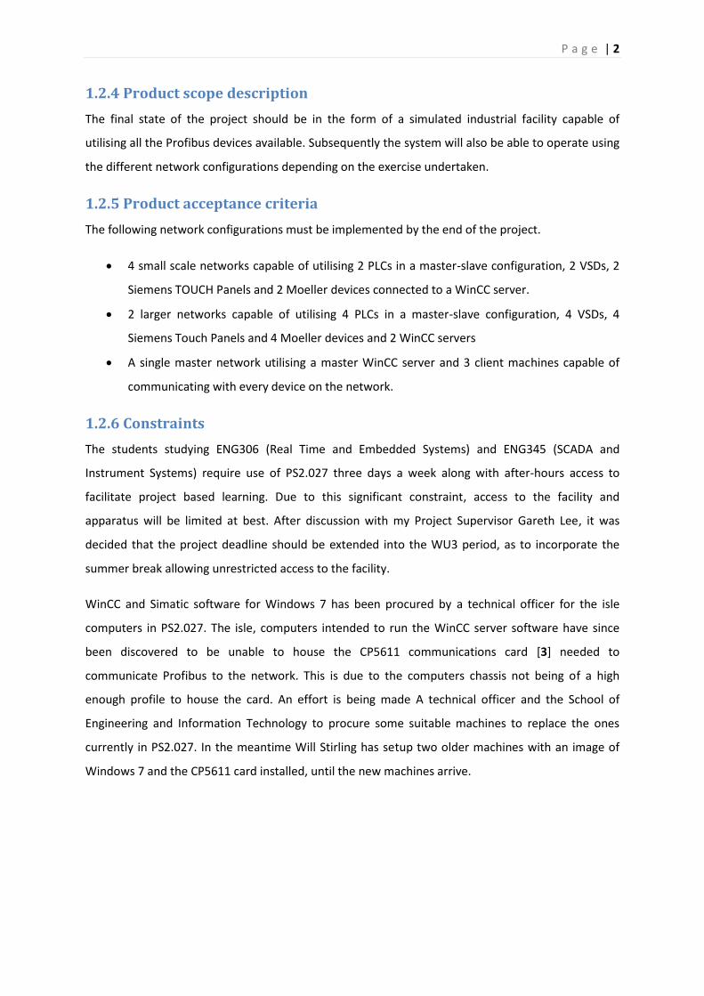
1.2.4 Product scope description
The final state of the project should be in the form of a simulated industrial facility capable of
utilising all the Profibus devices available. Subsequently the system will also be able to operate using
the different network configurations depending on the exercise undertaken.
1.2.5 Product acceptance criteria
The following network configurations must be implemented by the end of the project.
4 small scale networks capable of utilising 2 PLCs in a master-slave configuration, 2 VSDs, 2
Siemens TOUCH Panels and 2 Moeller devices connected to a WinCC server.
2 larger networks capable of utilising 4 PLCs in a master-slave configuration, 4 VSDs, 4
Siemens Touch Panels and 4 Moeller devices and 2 WinCC servers
A single master network utilising a master WinCC server and 3 client machines capable of
communicating with every device on the network.
1.2.6 Constraints
The students studying ENG306 (Real Time and Embedded Systems) and ENG345 (SCADA and
Instrument Systems) require use of PS2.027 three days a week along with after-hours access to
facilitate project based learning. Due to this significant constraint, access to the facility and
apparatus will be limited at best. After discussion with my Project Supervisor Gareth Lee, it was
decided that the project deadline should be extended into the WU3 period, as to incorporate the
summer break allowing unrestricted access to the facility.
WinCC and Simatic software for Windows 7 has been procured by a technical officer for the isle
computers in PS2.027. The isle, computers intended to run the WinCC server software have since
been discovered to be unable to house the CP5611 communications card [3] needed to
communicate Profibus to the network. This is due to the computers chassis not being of a high
enough profile to house the card. An effort is being made A technical officer and the School of
Engineering and Information Technology to procure some suitable machines to replace the ones
currently in PS2.027. In the meantime Will Stirling has setup two older machines with an image of
Windows 7 and the CP5611 card installed, until the new machines arrive.

P a g e | 3
1.3Project Objectives
1.3.1 Panel layout
The panels in the ICSE laboratory are currently not setup to properly incorporate the full range of
Profibus devices and associated cabling. The SEW VSD and motor combination have temporarily
been installed on two panels in order to provide a testing platform. The panels will also need to
incorporate a series of Profinet devices for future projects. Graeme has decided that redesigning the
layout of the panels would be best left until the completion of this project as by that stage John will
have a proper enclosure solution for the VSD and motor combination.
1.3.2 New Windows 7 computers
All computers in the ICSE Laboratory have now been updated to Windows 7. The computers located
on the bench under the window have been replaced with minitowers. This was because the previous
computers did not have high enough profile to install the CP5611 card needed for Profibus
communication.
1.3.3 SEW VSDs
After meeting with Associate Professor Graeme Cole and Technical Officer to discuss the instillation
of the SEW VSDs, it was discovered that the Movitrac B drives purchased to be installed in the ISCE
Laboratory were different to the model used by Brenton Walker during his thesis which were
Movitrac A drives. The model destined for the ICSE Laboratory are slimmer and have an external
user interface card that needs be installed before use. Like the model used by Brenton Walker, in
order for the VSD to communicate over Profibus it first has to be connected to a gateway via S-bus.
1.3.4 Installation of the Profibus network
The remainder of the Profibus network will need to be installed following the design layout set by
the ENG454 students.
1.3.5 WinCC SCADA development
Using the WinCC SCADA environment appropriate software will need to be developed in order to
display critical information specific to the system.
1.3.6 Instruction manuals
Appropriate documentation will need to be provided in order to instruct students on how to
correctly setup and configure the system and various components.
P a g e | 4
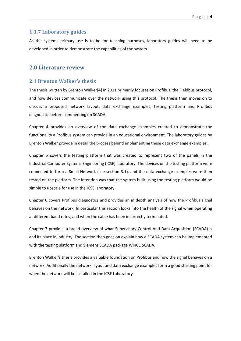
1.3.7 Laboratory guides
As the systems primary use is to be for teaching purposes, laboratory guides will need to be
developed in order to demonstrate the capabilities of the system.
2.0 Literature review
2.1 Brenton Walker's thesis
The thesis written by Brenton Walker[4] in 2011 primarily focuses on Profibus, the Fieldbus protocol,
and how devices communicate over the network using this protocol. The thesis then moves on to
discuss a proposed network layout, data exchange examples, testing platform and Profibus
diagnostics before commenting on SCADA.
Chapter 4 provides an overview of the data exchange examples created to demonstrate the
functionality a Profibus system can provide in an educational environment. The laboratory guides by
Brenton Walker provide in detail the process behind implementing these data exchange examples.
Chapter 5 covers the testing platform that was created to represent two of the panels in the
Industrial Computer Systems Engineering (ICSE) laboratory. The devices on the testing platform were
connected to form a Small Network (see section 3.1), and the data exchange examples were then
tested on the platform. The intention was that the system built using the testing platform would be
simple to upscale for use in the ICSE laboratory.
Chapter 6 covers Profibus diagnostics and provides an in depth analysis of how the Profibus signal
behaves on the network. In particular this section looks into the health of the signal when operating
at different baud rates, and when the cable has been incorrectly terminated.
Chapter 7 provides a broad overview of what Supervisory Control And Data Acquisition (SCADA) is
and its place in industry. The section then goes on explain how a SCADA system can be implemented
with the testing platform and Siemens SCADA package WinCC SCADA.
Brenton Walker's thesis provides a valuable foundation on Profibus and how the signal behaves on a
network. Additionally the network layout and data exchange examples form a good starting point for
when the network will be installed in the ICSE Laboratory.

P a g e | 5
2.2Laboratory guide 1:
Data Exchange between an S7 Slave and S7 Master.
2.2.1Executive summary
This guide[5] by Brenton Walker has been designed to facilitate the design and installation of a
Profibus network in the ICSE laboratory. By making use of the Siemens PLCs and other technologies
available, the aim of this manual is assist in establishing a typical Master-Slave relationship over
Profibus DP.
2.2.2Evaluation
The manual has been well set out and is presented in a logical order. It details the process of how to
correctly wire the Profibus connectors. This is extremely important, because incorrectly wired
connectors can lead to bus faults on the network. The remainder of the document details the
process of how to set up a Master-Slave configuration between two Siemens PLCs. The manual does
this rather well, however it does lack specific information relating to the function and location of
memory addresses. Without this information users will struggle to expand upon the basic example
provided.
2.2.3Recommendations
Information needs to be provided about the function of specific addresses, and how they can be
changed to alter the functionality.
2.3Laboratory guide 2:
Developing a Profibus Network Using Siemens Simatic S7And Easy 719DC-RC Moeller.
2.3.1Executive summary
This guide[6] by Brenton Walker was created to facilitate the design and installation of a Profibus
network inside the ICSE laboratory. This guide makes use of a Siemens Simatic S7 PLC and Moeller
Easy 719DC-RC to establish Master-Slave data exchange between the devices.
2.3.2 Evaluation
This document provides a step by step guide on how to configure the Moeller 719DC-RC for
communication over Profibus. The guide then details how to establish a Master-Slave relationship
between the Moeller and PLC. An example program been included on how to setup a basic data
exchange between the two devices. In the example there are several addresses and commands that
have not been properly documented. This makes it very difficult for an inexperienced user to
understand the process.
P a g e | 6
2.3.3 Recommendations
I have added descriptions for some of the memory addresses and commands, making the guide
easier to follow.
A change log has been included at the beginning of the document, outlining the changes made and
revision number and author.
2.4Laboratory guide 3:
Developing a Profibus Network Using a Siemens Simatic S7 PLC and a Danfoss FC102 Variable Speed
Drive.
2.4.1 Executive summary
This guide[7] by Brenton Walker has been created to facilitate the design and installation of a
Profibus network in the ICSE laboratory. This guide makes use of a Siemens PLC and Danfoss VSD,
with the aim of establishing a data exchange between the devices. The use of the Danfoss FC102
series has been chosen as this is the same model of VSD used within the Pilot Plant facility.
2.4.2 Evaluation
As this document focuses on the Danfoss VSD; an accurate evaluation as the Danfoss VSD was not
included in this project.
After reviewing the document it can be said to contain detail on a similar level to Laboratory guide 4.
2.5Laboratory guide 4:
Developing a Profibus Network Using a Siemens Simatic S7 PLC, SEW Movitrac A VSD and SEW
Profibus Gateway.
2.5.1 Executive summary
This guide[8] by Brenton Walker was created to facilitate the design and installation of a Profibus
network in the ICSE laboratory. By making use of the Siemens PLC, SEW Gateway and VSD the goal is
to establish typical Master-Slave data exchange over a Profibus DP network between the SEW
devices and Siemens PLC.
As the SEW VSD is unable to communicate over Profibus natively, the SEW Gateway is required to
act as an interpreter between the PLC and VSD.
P a g e | 7
2.5.2 Evaluation
As the SEW Movitrac A VSD that was used in this guide is different to the SEW Movitrac B VSD to be
implemented in the ICSE laboratory the evaluation will not be as accurate as if the VSD models
where the same.
The guide first addresses how to appropriately wire the VSD and Gateway. Minor explanation is
given as to why a 24V switch must be wired into DI01, but no information as when this switch should
be used.
The next section details the process of how to address the Gateway and VSD using the SEW
software, MOOVITOOLS MotionStudio and AddressTool. The AddressTool can supposedly be used to
set the address of the Gateway and VSD over the RS-485 link. The addresses could not be configured
this way as AddressTool would not detect the serial connection to the device. The connection was
not faulty, as MotionStudio was able to connect to the devices without error.
The following step in the guide is to configure the VSD Parameters, this is done using the Shell tool.
After some research it was discovered that the Shell tool does not support the model of VSD that will
be used in the ICSE laboratory. After more research I discovered that the parameters for this
particular VSD can only be set manually through the keypad interface after enabling a special menu.
The next step goes through the process of adding the VSD and Gateway to the Master system. This
section applied to both models of VSD and explained the process in detail.
The example program section shows how to control the speed of the VSD from the Master PLC over
Profibus. This section provides enough information for the user to implement the example. It does
not provide detailed enough description on the methods used to convert the setpoint and maximum
speed into a form the VSD will accept, however.
2.5.3 Recommendations
As there are so many differences in the configuration process between the Movitrac A and Movitrac
B VSDs the best solution was to create a separate guide for the Movitrac B drive. The new guide
addresses all the issues from the above section.

P a g e | 8
2.6 Laboratory guide 5:
Developing a Profibus Network Using Simatic TP177B Touch Panels.
2. 6.1 Executive summary
This guide[9] by Brenton Walker was created to facilitate the design and installation of a Profibus
network in the ICSE laboratory. This guide makes use of a Siemens PLC and the Siemens Touch Panel.
The aim of this guide is to provide instruction on how to establish a HMI for various systems or
devices on the Profibus network.
2.6.2 Evaluation
This document provides detailed instruction on how to create a HMI using the Siemens Touch Panel
and the program WinCC Flexible. The guide follows logical progression and explains everything in an
easy to understand manner. The guide does not document an error caused by a Microsoft SQL
Database conflict. This may be because the error was never encountered. A solution for the error
has since been documented.
2.6.3 Recommendations
A section has been included in the guide documenting the process on how to fix the Microsoft SQL
error.
2.6 Laboratory guide 6:
Using Siemens Simatic WINCC over Profibus.
2.7.1 Executive summary
This guide[10] by Brenton Walker was created to aid the design and installation Profibus network in
the ICSE laboratory. This guide makes use of a Siemens PLC and the Siemens SCADA program WinCC
SCADA [2] to facilitate with the instruction of how to configure a SCADA environment for use with
the Profibus network in the ICSE laboratory.
2.7.2 Evaluation
This document describes in great detail the process of configuring a SCADA system within WinCC
SCADA. This guide is very good at providing the necessary information that the user would need to
setup their own SCADA environment specific to the needs of their system.
2.8 Phase 1 handover report
The Phase 1 handover report [11] by the ENG 454 students documents the first step taken to
implement the Profibus network in the ICSE Laboratory. The report covers many of the early
constraints that needed to be addressed before the project could move ahead. The report was brief

P a g e | 9
and contained little detail on the processes involved. As a result the report failed meet the usual
Murdoch Engineering standards.
2.9 Phase 2 handover report
The Phase 2 handover report [12] by the ENG454 students redefines the project scope from the
Phase 1 handover report. The redesign of the network layout is introduced with the concept of a
termination box to isolate or link the individual bus segments. The report then attempts to recreate
some of the data exchange examples designed by Brenton Walker.
2.10 Phase 3 handover report
The Phase 3 handover report [13] focuses on expanding the network infrastructure and the creation
of a quick start guide to reduce the knowledge gap at handover. The most important piece of
information in this report is the solution to the Microsoft SQL database error encountered when
attempting to create a WinCC Flexible project for the Siemens Touch Panel.
2.11 Phase 4 handover report
The Phase 4 handover report [14] primarily focuses on expanding the network infrastructure to
encompass the entire ICSE Laboratory. The network expansion incorporates unorthodox wiring of
the Profibus connectors. There is no explanation or documentation as to why this way of wiring the
network works; the Siemens RS-485 repeater[15] was installed during the course of Phase 4.
3.0Network
The aim of this chapter is to supply Profibus infrastructure to the entire ICSE laboratory while
providing connectivity to the various Profibus devices and incorporating the termination boxes
(section 3.3) and Siemens RS-485 repeater [15] to facilitate the separation of bus segments.
3.1 Review
Upon conducting a review of the network infrastructure implemented at the start of this project it
was concluded that the cabling and connectors had not been installed in accordance to the revised
network diagrams provided in the ENG454 - Industrial Computer Systems Design reports [12] and
[13]. Further investigation revealed that the cable, that is meant to connect panel 4 and 5 [Figure 1],
was actually connecting panel 4 to 6. Cable provisioning for all the Profibus devices had not been
made, meaning that additional cabling and connectors will need to be added to the network
infrastructure to provide full connectivity. Before work can progress the network infrastructure
issues needed to be addressed to provide a solid foundation for the remainder of the project.

P a g e | 10
Figure 1 - Network layout
3.2Network design
Before any adjustments were made to the network infrastructure a review was conducted to
consolidate the functionality that each segment needed to provide.
3.2.1 Single network
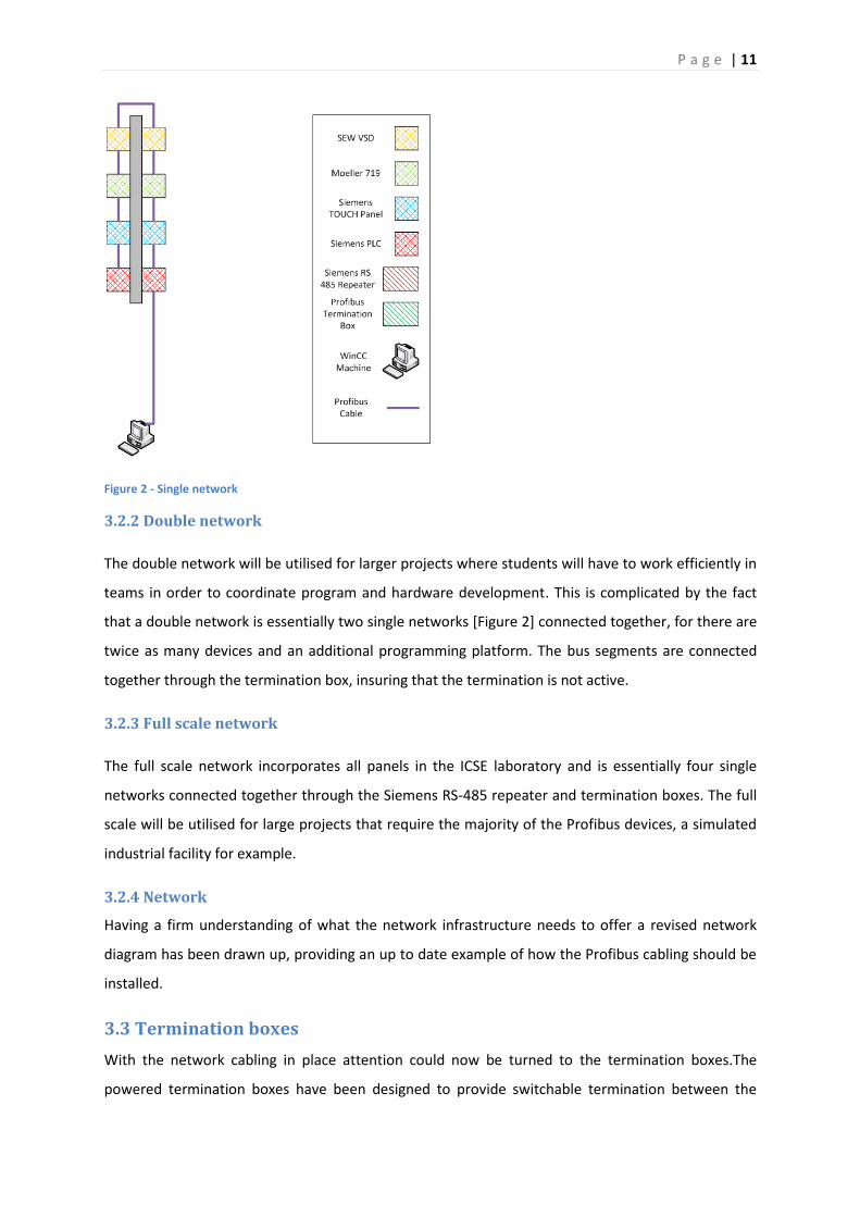
The single network configuration [Figure 2] has been designed so that students will need to work in
teams as the segment encompasses two panels. The network will be connected to a server
computer via Profibus form which the students will be able to program and monitor the devices. The
termination box will need to be active in order to prevent any interference from the remainder of
the network.
P a g e | 11
Figure 2 - Single network
3.2.2 Double network
The double network will be utilised for larger projects where students will have to work efficiently in
teams in order to coordinate program and hardware development. This is complicated by the fact
that a double network is essentially two single networks [Figure 2] connected together, for there are
twice as many devices and an additional programming platform. The bus segments are connected
together through the termination box, insuring that the termination is not active.
3.2.3 Full scale network
The full scale network incorporates all panels in the ICSE laboratory and is essentially four single
networks connected together through the Siemens RS-485 repeater and termination boxes. The full
scale will be utilised for large projects that require the majority of the Profibus devices, a simulated
industrial facility for example.
3.2.4 Network
Having a firm understanding of what the network infrastructure needs to offer a revised network
diagram has been drawn up, providing an up to date example of how the Profibus cabling should be
installed.
3.3 Termination boxes
With the network cabling in place attention could now be turned to the termination boxes.The
powered termination boxes have been designed to provide switchable termination between the
P a g e | 12
networks. These termination boxes will facilitate the combination and separation of networks into
the different configurations as needed.
The termination box can be switched between two modes, one where powered termination is
provided to both bus segments terminating and isolating them. The second provides a through
connection from one segment to the other joining the two networks together.
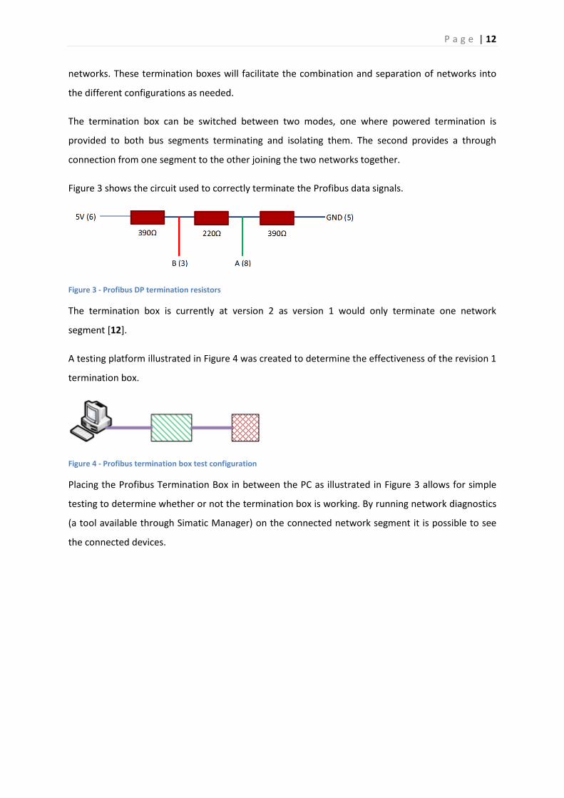
Figure 3 shows the circuit used to correctly terminate the Profibus data signals.
Figure 3 - Profibus DP termination resistors
The termination box is currently at version 2 as version 1 would only terminate one network
segment [12].
A testing platform illustrated in Figure 4 was created to determine the effectiveness of the revision 1
termination box.
Figure 4 - Profibus termination box test configuration
Placing the Profibus Termination Box in between the PC as illustrated in Figure 3 allows for simple
testing to determine whether or not the termination box is working. By running network diagnostics
(a tool available through Simatic Manager) on the connected network segment it is possible to see
the connected devices.

P a g e | 13
Figure 5 - Profibus termination box version 2 Test
Figure 5 shows that two devices are visible on the network with address 0 representing the PC and
15 representing the PLC. This means that the termination box is providing a through connection to
the other segment.
After changing the switch position on the termination box and running the network diagnostics again
the results were the same as shown in Figure 5. This proves that the Profibus signal is not being
terminated in either case.
Revision of the termination box wiring [Figure 6] showed that there is only one set of termination
resistors that where being used to provide termination for both bus segments. This means that
when the termination is powered the Profibus signal is still able to pass from segment to segment
bypassing the terminating resistors, rendering the termination box ineffective.
P a g e | 14
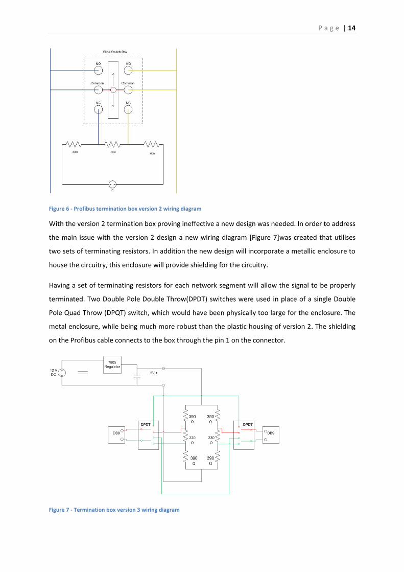
Figure 6 - Profibus termination box version 2 wiring diagram
With the version 2 termination box proving ineffective a new design was needed. In order to address
the main issue with the version 2 design a new wiring diagram [Figure 7]was created that utilises
two sets of terminating resistors. In addition the new design will incorporate a metallic enclosure to
house the circuitry, this enclosure will provide shielding for the circuitry.
Having a set of terminating resistors for each network segment will allow the signal to be properly
terminated. Two Double Pole Double Throw(DPDT) switches were used in place of a single Double
Pole Quad Throw (DPQT) switch, which would have been physically too large for the enclosure. The
metal enclosure, while being much more robust than the plastic housing of version 2. The shielding
on the Profibus cable connects to the box through the pin 1 on the connector.
Figure 7 - Termination box version 3 wiring diagram
P a g e | 15
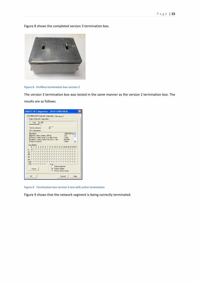
Figure 8 shows the completed version 3 termination box.
Figure 8 - Profibus termination box version 3
The version 3 termination box was tested in the same manner as the version 2 termination box. The
results are as follows.
Figure 9 - Termination box version 3 test with active termination
Figure 9 shows that the network segment is being correctly terminated.

P a g e | 16
Figure 10 - Profibus Termination Box Revision 2 Test Connected
Figure 10 shows that the PC and PLC are visible on the network indicating that the Profibus signal is
passing through the termination box correctly.
Version 3 of the termination box was not without its errors. During the first part of the testing
process it became apparent that the Profibus signal was being stopped from reaching the other bus
segment. After testing the internal connections it was discovered that the signal wires had been
crossed, stopping the signal from passing between the bus segments. After reconnecting the wires
correctly the test was run again and the termination box was found to be in full working order. As a
result of the successful testing another termination box will need to be constructed to complete the
network.
P a g e | 17
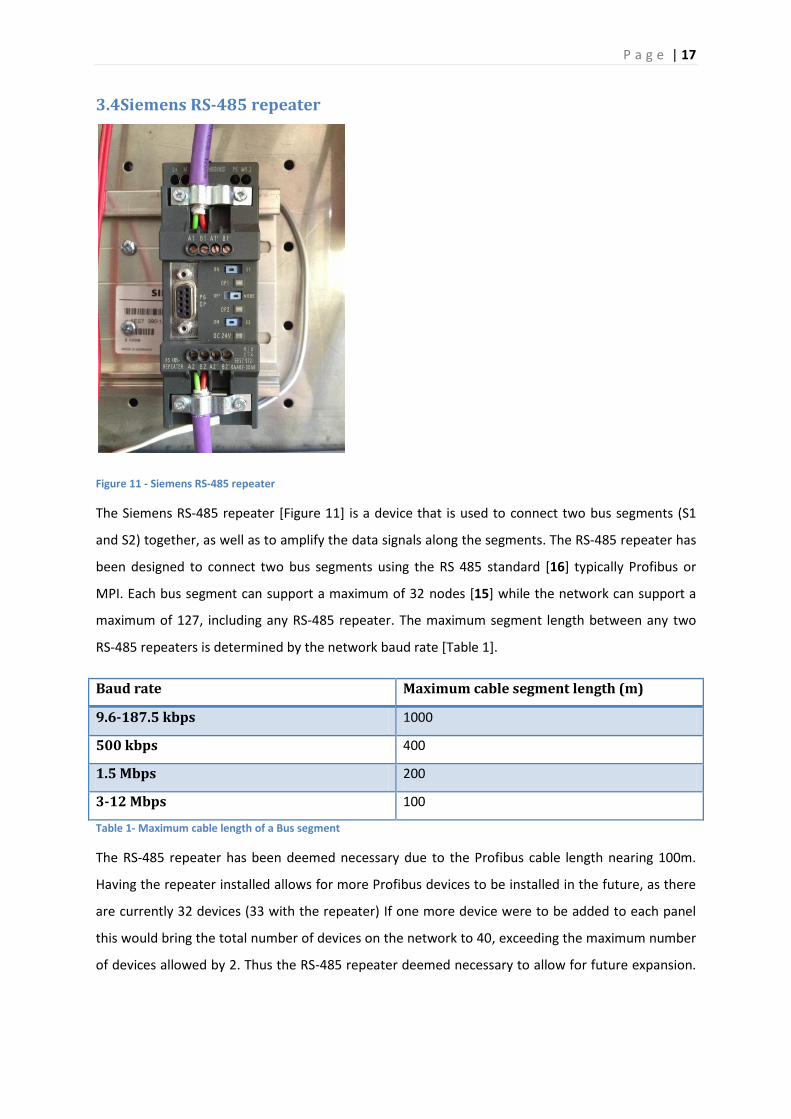
3.4Siemens RS-485 repeater
Figure 11 - Siemens RS-485 repeater
The Siemens RS-485 repeater [Figure 11] is a device that is used to connect two bus segments (S1
and S2) together, as well as to amplify the data signals along the segments. The RS-485 repeater has
been designed to connect two bus segments using the RS 485 standard [16] typically Profibus or
MPI. Each bus segment can support a maximum of 32 nodes [15] while the network can support a
maximum of 127, including any RS-485 repeater. The maximum segment length between any two
RS-485 repeaters is determined by the network baud rate [Table 1].
Baud rate Maximum cable segment length (m)
9.6-187.5 kbps 1000
500 kbps 400
1.5 Mbps 200
3-12 Mbps 100
Table 1- Maximum cable length of a Bus segment
The RS-485 repeater has been deemed necessary due to the Profibus cable length nearing 100m.
Having the repeater installed allows for more Profibus devices to be installed in the future, as there
are currently 32 devices (33 with the repeater) If one more device were to be added to each panel
this would bring the total number of devices on the network to 40, exceeding the maximum number
of devices allowed by 2. Thus the RS-485 repeater deemed necessary to allow for future expansion.
P a g e | 18
The repeater provides a convenient termination point between panels 4 and 5, eliminating the need
for a third termination box.
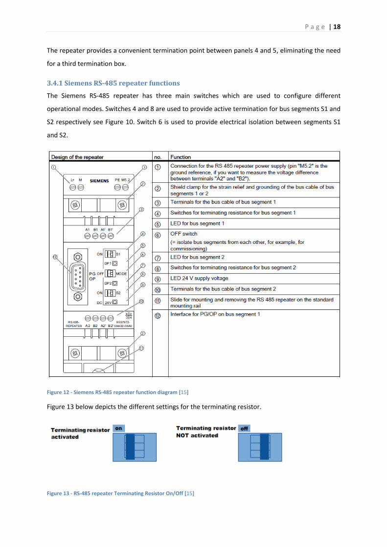
3.4.1 Siemens RS-485 repeater functions
The Siemens RS-485 repeater has three main switches which are used to configure different
operational modes. Switches 4 and 8 are used to provide active termination for bus segments S1 and
S2 respectively see Figure 10. Switch 6 is used to provide electrical isolation between segments S1
and S2.
Figure 12 - Siemens RS-485 repeater function diagram [15]
Figure 13 below depicts the different settings for the terminating resistor.
Figure 13 - RS-485 repeater Terminating Resistor On/Off [15]
P a g e | 19
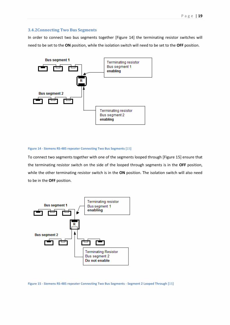
3.4.2Connecting Two Bus Segments
In order to connect two bus segments together [Figure 14] the terminating resistor switches will
need to be set to the ON position, while the isolation switch will need to be set to the OFF position.
Figure 14 - Siemens RS-485 repeater Connecting Two Bus Segments [15]
To connect two segments together with one of the segments looped through [Figure 15] ensure that
the terminating resistor switch on the side of the looped through segments is in the OFF position,
while the other terminating resistor switch is in the ON position. The isolation switch will also need
to be in the OFF position.
Figure 15 - Siemens RS-485 repeater Connecting Two Bus Segments - Segment 2 Looped Through [15]
P a g e | 20
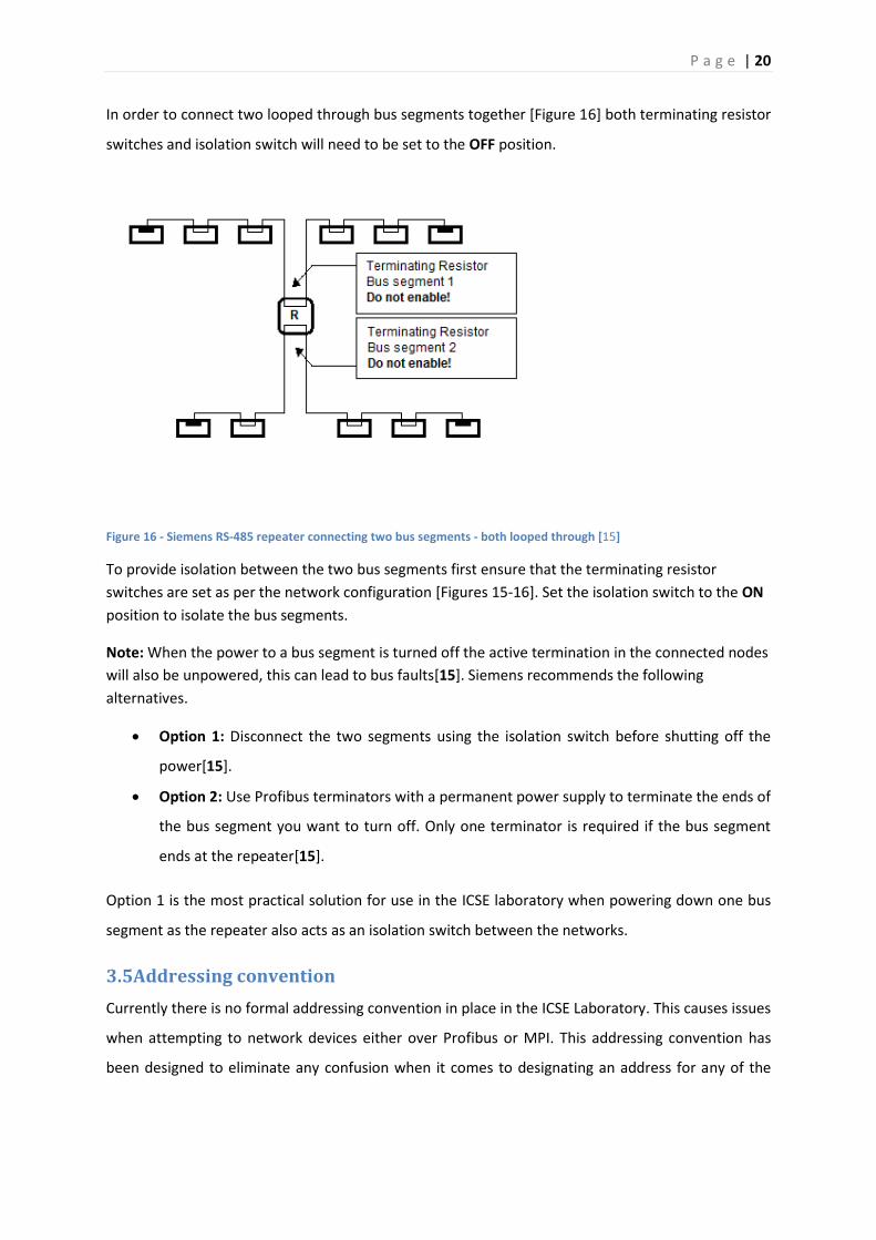
In order to connect two looped through bus segments together [Figure 16] both terminating resistor
switches and isolation switch will need to be set to the OFF position.
Figure 16 - Siemens RS-485 repeater connecting two bus segments - both looped through [15]
To provide isolation between the two bus segments first ensure that the terminating resistor
switches are set as per the network configuration [Figures 15-16]. Set the isolation switch to the ON
position to isolate the bus segments.
Note: When the power to a bus segment is turned off the active termination in the connected nodes
will also be unpowered, this can lead to bus faults[15]. Siemens recommends the following
alternatives.
Option 1: Disconnect the two segments using the isolation switch before shutting off the
power[15].
Option 2: Use Profibus terminators with a permanent power supply to terminate the ends of
the bus segment you want to turn off. Only one terminator is required if the bus segment
ends at the repeater[15].
Option 1 is the most practical solution for use in the ICSE laboratory when powering down one bus
segment as the repeater also acts as an isolation switch between the networks.
3.5Addressing convention
Currently there is no formal addressing convention in place in the ICSE Laboratory. This causes issues
when attempting to network devices either over Profibus or MPI. This addressing convention has
been designed to eliminate any confusion when it comes to designating an address for any of the

P a g e | 21
MPI or Profibus devices. The address range for Profibus and MPI is 0-127. This convention was first
implemented by Brenton Walker during his thesis in 2011[4].
The addressing convention is governed by a prefix and suffix designated by device type and panel
number respectively [Table 2].
Device Type Assigned Prefix
Personal Computer (PC) 0
Programmable Logic Controller (PLC) 1
Human Machine Interface (HMI) 2
Moeller 719 3
SEW Gateway 4
Server 5
Table 2 - Network addressing prefix[4]
For example the PLC located on panel 3 will have an address of 13 for both Profibus and MPI
purposes.
As multiple SEW VSDs connect through the same gateway device, it became apparent that it would
be necessary to distinguish between the VSDs on the SBus (section 4.12.1) network. The following
addressing convention [Table 3]was developed for the VSDs on the SBus network.
Panel number Group Address SBus Address
Odd 0 1
Even 0 2
Table 3 - SBus addressing scheme
4.0 SEW MOVITRAC B VSD
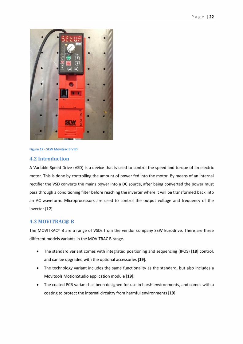
4.1 Overview
As the SEW VSD [Figure 17] is a new device in the learning environment, appropriate documentation
needs to be drawn up to provide detailed information on the device and how it functions.
P a g e | 22
Figure 17 - SEW Movitrac B VSD
4.2 Introduction
A Variable Speed Drive (VSD) is a device that is used to control the speed and torque of an electric
motor. This is done by controlling the amount of power fed into the motor. By means of an internal
rectifier the VSD converts the mains power into a DC source, after being converted the power must
pass through a conditioning filter before reaching the inverter where it will be transformed back into
an AC waveform. Microprocessors are used to control the output voltage and frequency of the
inverter.[17]
4.3 MOVITRAC® B
The MOVITRAC® B are a range of VSDs from the vendor company SEW Eurodrive. There are three
different models variants in the MOVITRAC B range.
The standard variant comes with integrated positioning and sequencing (IPOS) [18] control,
and can be upgraded with the optional accessories [19].
The technology variant includes the same functionality as the standard, but also includes a
Movitools MotionStudio application module [19].
The coated PCB variant has been designed for use in harsh environments, and comes with a
coating to protect the internal circuitry from harmful environments [19].

P a g e | 23
4.4 Optional Accessories
These are the accessories that have been purchased with the unit for use in the Industrial Computer
Systems Laboratory.
4.4.1 FBG11B keypad
The FBG11B keypad [Figure 18] is an optional front interface for the VSD. The keypad provides the
user with a simple interface from where the device can be programmed. The keypad also outputs
basic operating information such as speed (RPM), frequency (Hz), current (A) and error codes by
means of the LCD display.
Figure 18 - FBG11B keypad
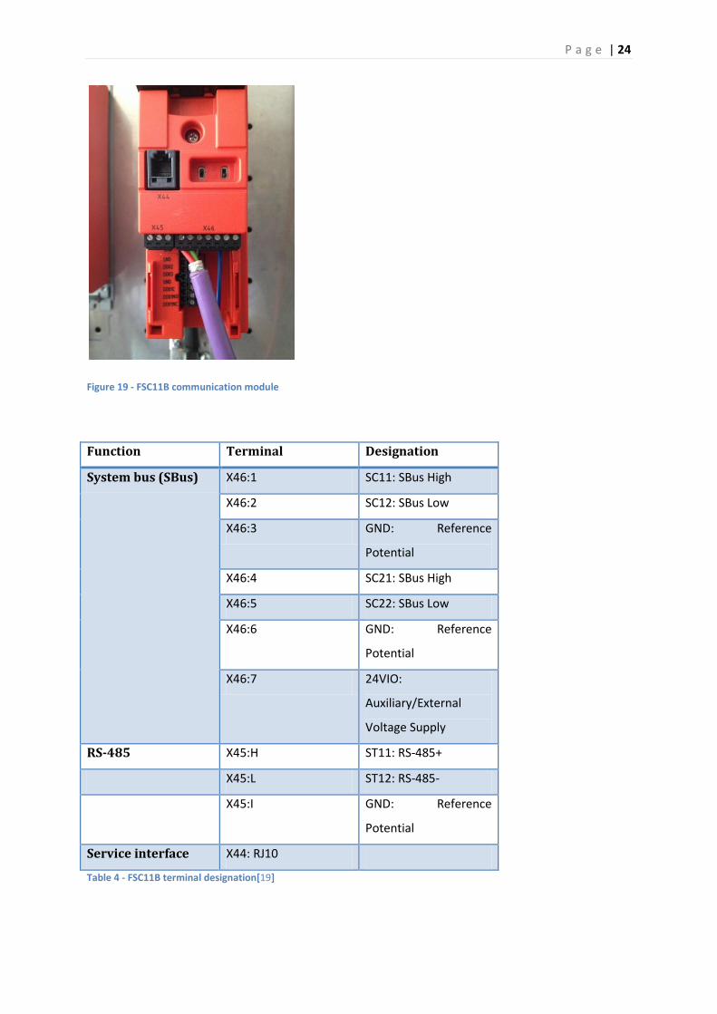
4.4.2 FSC11B communication module
The FSC11B communication module [Figure 19] allows the VSD to communicate with devices using
RS-485 [19] standard and SBus protocol [19]. The module also provides a service connection by
means of an RJ10 [20] connector - this connection can be used to monitor the drive and perform
diagnostics. The terminal designation for the module can be seen in Table 4.
P a g e | 24
Figure 19 - FSC11B communication module
Function Terminal Designation
System bus (SBus) X46:1 SC11: SBus High
X46:2 SC12: SBus Low
X46:3 GND: Reference
Potential
X46:4 SC21: SBus High
X46:5 SC22: SBus Low
X46:6 GND: Reference
Potential
X46:7 24VIO:
Auxiliary/External
Voltage Supply
RS-485 X45:H ST11: RS-485+
X45:L ST12: RS-485-
X45:I GND: Reference
Potential
Service interface X44: RJ10
Table 4 - FSC11B terminal designation[19]

P a g e | 25
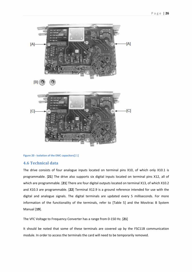
4.5 EMC capacitors
The EMC capacitors needed to be isolated due to that fact that the earth leakage current was
causing the breakers in the ICSE laboratory to trip upon powering up the VSDs.
In order to reduce the earth leakage current the EMC capacitors must be isolated. [21] Isolating the
EMC capacitors stops the earth leakage current from flowing through them. By isolating the EMC
capacitors the EMC filter is no longer functional. [21]
To isolate the EMC capacitors: [21]
First disconnect the unit from any power source and ensure that the circuitry has been
discharged.
Remove the protective cover;
o Avoid touching any circuitry
Remove the screws at position [A] [Figure 20].
Install the plastic isolators [B] in screw holes [A][Figure 20].
Fasten screws to the unit [C] [Figure 20].
Reassemble the unit.
P a g e | 26
Figure 20 - Isolation of the EMC capacitors[21]
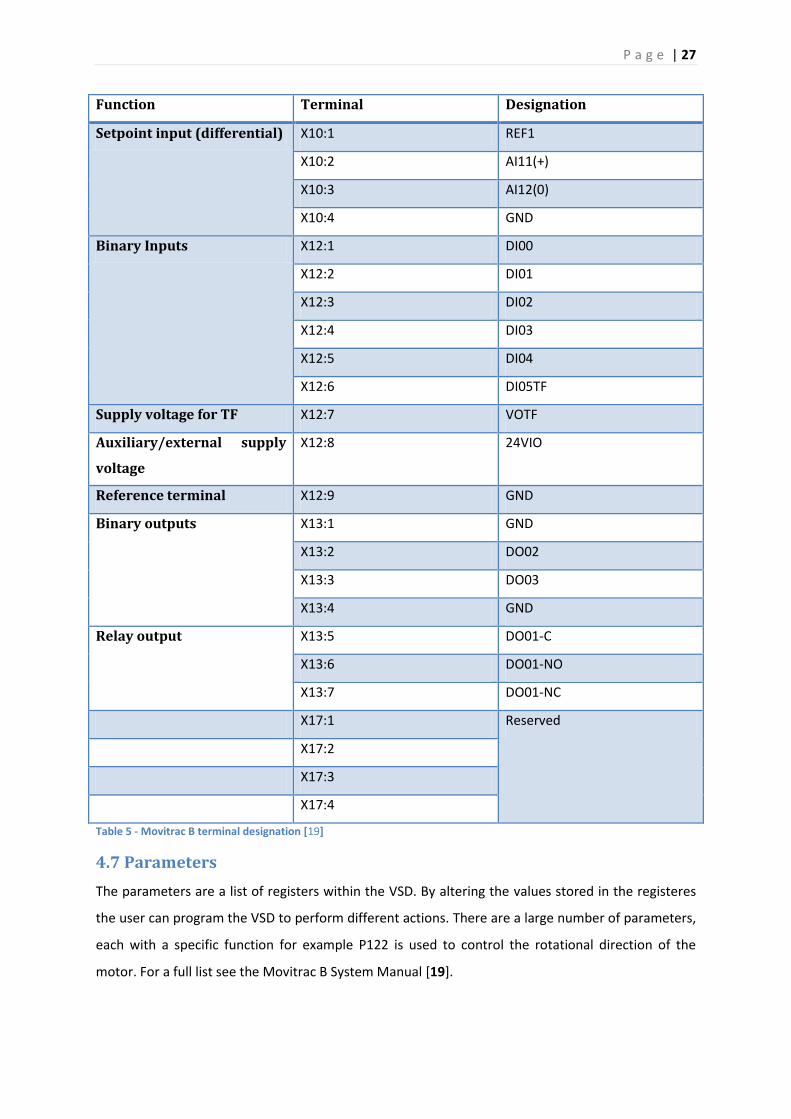
4.6 Technical data
The drive consists of four analogue inputs located on terminal pins X10, of which only X10.1 is
programmable. [21] The drive also supports six digital inputs located on terminal pins X12, all of
which are programmable. [21] There are four digital outputs located on terminal X13, of which X10.2
and X10.3 are programmable. [22] Terminal X12.9 is a ground reference intended for use with the
digital and analogue signals. The digital terminals are updated every 5 milliseconds. For more
information of the functionality of the terminals, refer to [Table 5] and the Movitrac B System
Manual [19].
The VFC Voltage to Frequency Converter has a range from 0-150 Hz. [21]
It should be noted that some of these terminals are covered up by the FSC11B communication
module. In order to access the terminals the card will need to be temporarily removed.
P a g e | 27
Function Terminal Designation
Setpoint input (differential) X10:1 REF1
X10:2 AI11(+)
X10:3 AI12(0)
X10:4 GND
Binary Inputs X12:1 DI00
X12:2 DI01
X12:3 DI02
X12:4 DI03
X12:5 DI04
X12:6 DI05TF
Supply voltage for TF X12:7 VOTF
Auxiliary/external supply
voltage
X12:8 24VIO
Reference terminal X12:9 GND
Binary outputs X13:1 GND
X13:2 DO02
X13:3 DO03
X13:4 GND
Relay output X13:5 DO01-C
X13:6 DO01-NO
X13:7 DO01-NC
X17:1 Reserved
X17:2
X17:3
X17:4
Table 5 - Movitrac B terminal designation [19]
4.7 Parameters
The parameters are a list of registers within the VSD. By altering the values stored in the registeres
the user can program the VSD to perform different actions. There are a large number of parameters,
each with a specific function for example P122 is used to control the rotational direction of the
motor. For a full list see the Movitrac B System Manual [19].
P a g e | 28
4.8 Startup
For information on setting up the VSD and using the keypad please see appendices A1 and A2.
4.9 Operation and service
4.9.1 Data backup
This data backup ability allows data, mainly parameter settings, to be downloaded from the drive to
the keypad or uploaded from the keypad to the drive [19]. This is a highly useful tool, and can be
used to transfer settings between multiple VSDs.
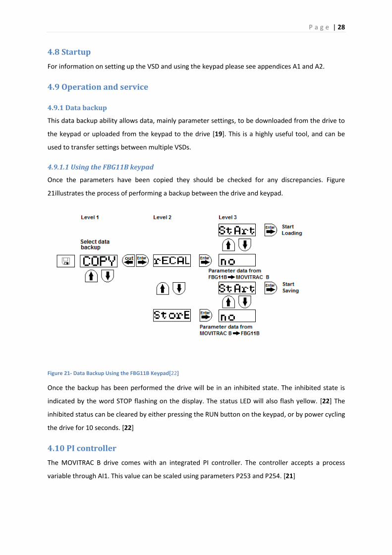
4.9.1.1 Using the FBG11B keypad
Once the parameters have been copied they should be checked for any discrepancies. Figure
21illustrates the process of performing a backup between the drive and keypad.
Figure 21- Data Backup Using the FBG11B Keypad[22]
Once the backup has been performed the drive will be in an inhibited state. The inhibited state is
indicated by the word STOP flashing on the display. The status LED will also flash yellow. [22] The
inhibited status can be cleared by either pressing the RUN button on the keypad, or by power cycling
the drive for 10 seconds. [22]
4.10 PI controller
The MOVITRAC B drive comes with an integrated PI controller. The controller accepts a process
variable through AI1. This value can be scaled using parameters P253 and P254. [21]
P a g e | 29
The setpoint can be changed by either using any one of the six pre-configured setpoints specifying
the setpoint via the RS-485 or SBus interface[21]. Lastly, the setpoint can be adjusted via the local
setpoint potentiometer. See parameter P100 for more details on how to configure the setpoint
source. [21]
The PI controller's manipulated variable is the speed setpoint. It is limited by the minimum and
maximum speed P301 and P302 respectively. [21] While the PI controller is operating the ramping
capabilities are disabled. [21]
4.10.1 Parameter settings
The PI controller can be activated through parameter P250. Storing 0 in the parameter disables the
controller. Storing 1 in the parameter will run the controller into Normal mode, while storing 2 in the
parameter will run the controller in Inverted mode. [21] Running the controller in Normal mode
means that the manipulated variable will be increased in response to a positive increase in the
process variable, [21] while Inverted mode means that the manipulated variable will be increased in
response to a decrease in the process variable. [21]
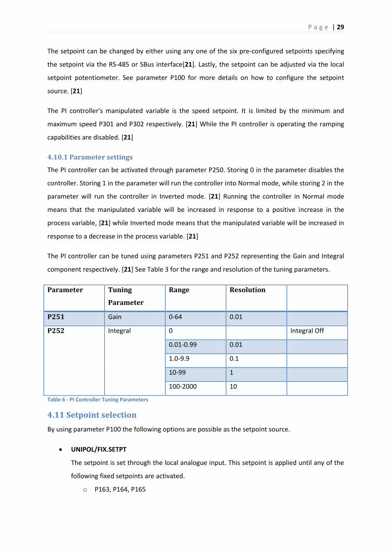
The PI controller can be tuned using parameters P251 and P252 representing the Gain and Integral
component respectively. [21] See Table 3 for the range and resolution of the tuning parameters.
Parameter Tuning
Parameter
Range Resolution
P251 Gain 0-64 0.01
P252 Integral 0 Integral Off
0.01-0.99 0.01
1.0-9.9 0.1
10-99 1
100-2000 10
Table 6 - PI Controller Tuning Parameters
4.11 Setpoint selection
By using parameter P100 the following options are possible as the setpoint source.
UNIPOL/FIX.SETPT
The setpoint is set through the local analogue input. This setpoint is applied until any of the
following fixed setpoints are activated.
o P163, P164, P165

P a g e | 30
In order to use the setpoint dial on the keypad, parameter P121 will need to be activated. By
storing 1 in P121 the output from the setpoint generator on the keypad will be added to any
other setpoint source - including fixed setpoints. [21] Storing a 2 in P121 will also add the
setpoint generated to any other setpoint source, but will not affect fixed setpoints. Storing a
0 in the parameter will cause the drive to ignore any value generated from this source. [21]
With RS-485 and SBus the controller will set any negative setpoints to zero. Since the sign of the
setpoint determines the rotational direction the sign must always be positive. [21]
RS-485
The RS-485 link provides the setpoint.
SBus
The SBus link provides the setpoint. See Actual Value Acquisition - RS485 and SBus.
The following sources are not available when operating the PI controller. If any of these
setpoints are selected the drive will automatically set them to zero. [21]
Motor Potentiometer
FIX.SETPT + AI1
FIX.SETPT * AI1
4.12 Actual value acquisition
The actual value input can be acquired through AI1 as a unipolar signal. The signal can be read using
several different modes by configuring P253. [21]
Stored Value Mode Output PI Controller Actual
Value
0 Inactive N/A
1 0-10 V 0-100% PI
5 0-20 mA 0-100%
6 4-20 mA 0-100%
Table 7 - P253 PI Controller Actual Value Mode
The signal detected can be scaled by a factor ranging between 0.1 and 10 using P254. This scaling
factor has a default value of 1.0 and a resolution of 0.1. [21]
P255 can used to provide an offset for the scaled value. The scaled value with offset is then
considered to be the actual value for the controller. [21]

P a g e | 31
4.12.1 RS-485 and SBus
These values can be read over RS-485 and SBus through the following parameters. [21]
Parameter Setpoint Description Default Setting
P870 PO1 CONTROL WORD 1
P871 PO2 SPEED
P872 PO3 NO FUNCTION
Table 8 - Process Output Words
Parameters P870 to P872 [Table 8] can be used to determine the value of process data words PO1,
PO2 and PO3. This is necessary so that the drive can allocate the appropriate setpoints. [21]
Parameters P873 to P875 [Table 9] can be used to determine the value of process input data words
PI1, PI2 and PI3. This is necessary so that the drive can allocate the appropriate actual values. [21]
Parameter Setpoint Description Default Setting
P873 PI1 STATUS WORD 1
P874 PI2 SPEED
P875 PI3 NO FUNCTION
Table 9 - Process Input Words
Table 9 shows the assignment and functionality of the PI data word
Value Function Description
0 No Function The content of the PO Data
word is ignored
1 Setpoint Speed Speed setpoint entry in rpm
5 Max Speed Maximum speed (P302)
8 Ramp Ramp time for setpoint
selection (P130/P131)
9 Control Word 1 Control signals for start/stop
etc
10 Control Word 2 Control signals for start/stop
etc
11 Setpoint Speed % Speed setpoint entry in % of
P302
12 IPOS PO Data Specification of a 16-bit coded

P a g e | 32
value for IPOSPLUS®
13 PI Controller Setpoint % PI Controller Setpoint
Table 10 - Process Output Data Word Assignments[19]
Table 10 shows the assignment and functionality of the PI data word.
Value Function Description
0 No Function The content of this PI data
word is 0000 (HEX)
1 Actual Speed Current actual speed of the VSD
in rpm
2 Output Current Momentary output current of
the inverter in % of IN
3 Active Current Momentary active current of
the inverter in % of IN
6 Status Word 1 Status information of the
inverter
7 Status Word 2 Status information of the
inverter
8 Actual Speed % Momentary actual speed of the
VSD in % of P302
9 IPOS PI Data IPOS process input data
10 PI Controller Actual value % Actual value of the PI controller
Table 11 - Process Input Data Word Assignments[19]
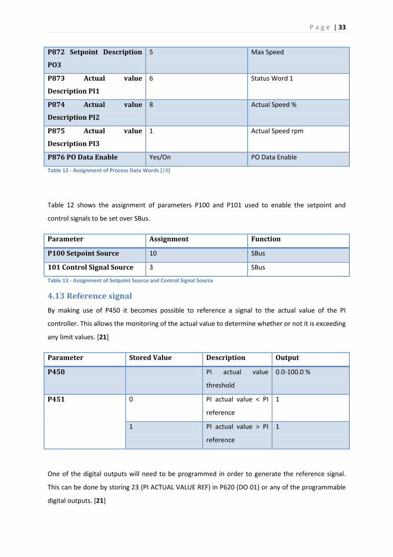
Table 11 shows the parameter configuration used to enable setpoint control, where the setpoint is
entered as a value between 0-100. This value is then read as a percentage of the maximum speed.
Parameter Assignment Function
P870 Setpoint Description
PO1
9 Control Word 1
P871 Setpoint Description
PO2
11 Setpoint Speed %
P a g e | 33
P872 Setpoint Description
PO3
5 Max Speed
P873 Actual value
Description PI1
6 Status Word 1
P874 Actual value
Description PI2
8 Actual Speed %
P875 Actual value
Description PI3
1 Actual Speed rpm
P876 PO Data Enable Yes/On PO Data Enable
Table 12 - Assignment of Process Data Words [19]
Table 12 shows the assignment of parameters P100 and P101 used to enable the setpoint and
control signals to be set over SBus.
Parameter Assignment Function
P100 Setpoint Source 10 SBus
101 Control Signal Source 3 SBus
Table 13 - Assignment of Setpoint Source and Control Signal Source
4.13 Reference signal
By making use of P450 it becomes possible to reference a signal to the actual value of the PI
controller. This allows the monitoring of the actual value to determine whether or not it is exceeding
any limit values. [21]
Parameter Stored Value Description Output
P450 PI actual value
threshold
0.0-100.0 %
P451 0 PI actual value < PI
reference
1
1 PI actual value > PI
reference
1
One of the digital outputs will need to be programmed in order to generate the reference signal.
This can be done by storing 23 (PI ACTUAL VALUE REF) in P620 (DO 01) or any of the programmable
digital outputs. [21]
P a g e | 34
4.14 Inverter control
It is possible to determine the rotational direction through the use of the terminal assigned to
CW/Stop and CCW/Stop; these terminals are by default X12.1 and X12.2 (DI 01 and DI 02). [21]
The inverter increases the speed up to the minimum speed (P301) through the use of the speed
ramping function (P130). Once the minimum speed has been reached the PI controller takes over.
4.15 Conclusion
The SEW Movitrac B VSD is a highly complex device with many different capabilities. As the VSD is
not limited for use solely with Profibus, it opens up the opportunity for students to incorporate the
device into other projects.
5.0 VSD operational manuals
5.1 Aim
VSD manuals needed to be created in order to provide students with access to information on how
to operate the VSDs. As most laboratories run for two to four hours, it is unrealistic for students to
have to read through the manufacture's manuals during laboratories, as this is extremely time
consuming.
5.2 Method
As the manuals are primarily aimed at students, they need to provide enough technical detail while
remaining simple and easy to follow.
After spending much time studying the VSD manuals[21][19] and Laboratory guide 4 [8], it became
apparent that there were significant differences between the VSD model used by Brenton Walker
and the model purchased for use in the ICSE Laboratory. The most significant difference is that the
VSD parameters are unable to be manipulated through the MotionStudio software due to the Shell
tool now supporting the MOVITRAC B VSD series. The parameters can only be altered through the
long menu system on the keypad [19].
An operational manual of this nature needs to contain enough technical information while reaming
simple and easy to follow. In order to achieve this, a step by step approach was taken when creating
the layout for the operational manual.
Having decided on a layout and overall structure of the operational manual, consideration turned to
what content the operational manual should contain. The operational manual should provide
P a g e | 35
students with the information on how to manually operate the VSD using only the keypad. After
establishing this basic level of understanding the next operational manual will provide instructions
on how to configure the VSD and Gateway for operation on the Profibus network. After detailing the
process of configuring the devices for Profibus, an example will be provided demonstrating the basic
capabilities of the system.
The process of gathering the appropriate material consisted of documenting every step taken from
first beginning a new project. This documentation process included many screen shots in order to
provide students with visual cues accompanied by detailed instructions to facilitate the learning
process.
Then next step was to compile the material into a coherent document the fitted with the simple step
by step structure.
5.3 Conclusion
Once finished, the operational manuals presented as well structured documents that contained
enough detail for students to be able to use the operational manuals as a good starting point if they
wish to conduct a more intricate project. The operational manuals having achieved the goals that
were set at the beginning of the process would be deemed successful.
6.0 Future recommendations
This chapter looks at the recommended upgrades for the system, as the current environment only
supports basic functionality, providing students with a foundation on which to build projects. With
further improvements the Siemens WinCC and Profibus system can provide improved functionality,
providing students with a powerful platform from which to build and monitor projects. Having a
flexible system like this will allow support for a diverse range of projects.
6.1 SEW VSD and motor system installation
The remaining SEW VSDs and motors will need to be installed on the Industrial Computer Systems
Engineering (ICSE) Laboratory panels. A technical officer has been working on a safe way to mount
the units on the panels. As part of the panel redesign process, provision is being made for the SEW
VSD and motor systems. Associate Professor Graeme Cole and Technical Officers should be
consulted in regard to the panel redesign process, while a technical officer will need to be contacted
with regards to the installation of the SEW VSD and motor systems.

P a g e | 36
6.2 Siemens and SEW Eurodrive updated software packages
As the Windows 7 upgrades have now been completed, it is important that the laboratory guides be
updated to include all changes related to the updated Siemens and SEW Eurodrive software
packages. All knowledge for the system is currently based on the Siemens and SEW Eurodrive
software packages that run on the Windows XP operating system. The new Siemens software
package TIA Portal [23] includes a universal launcher from which all Siemens programs are launched
from. For any information regarding the installation of the software packages contact A technical
officer.
6.3 WinCC SCADA server development
As the WinCC SCADA server was not covered in detail at any stage of this project, the next developer
should read chapter 7 of Brenton Walker's thesis [4]and Laboratory guide 6 [10]as his thesis covers
the WinCC SCADA server in more detail. The program developed by Brenton Walker only utilises the
base capability of the WinCC software package, a more comprehensive program should be
developed using the multi-project capability in order to setup client and server machines. Graeme
Cole will need to be contacted about further developing the WinCC SCADA program.
6.4 Danfoss VSD implementation
The Danfoss VSDs are yet to be implemented in the ICSE Laboratory, as they require three phase
power to be supplied and the panels in the ICSE Laboratory only supply single phase power. As the
three phase power outlet is located at the front of the ICSE Laboratory, a solution proposed by
Graeme Cole was to have the Danfoss VSDs mounted on a mobile platform, which could then be
stored away when not in use. Having the VSDs mounted on a mobile platform would allow them to
be placed near the appropriate power source. The network infrastructure will have to be adjusted
accordingly, to allow for the cable provisioning. Associate Professor Graeme Cole and Technical
Officer will need to be consulted with regards to all upgrades concerning the Danfoss VSDs. For more
information regarding the Danfoss VSDs please see Brenton Walker's thesis [4] and Laboratory guide
3 [7].
6.5 Tutorial development
More comprehensive tutorials need to be created, as the current collection of laboratory guides and
manuals only provide basic knowledge in order for students to operate the system. These tutorials
should provide more detailed examples utilising multiple Profibus devices, while providing the
opportunity for the students to expand upon the example. These tutorials should follow a format
similar to that of the ENG305 - PLC Systems and ENG306 - Real Time and Embedded Systems

P a g e | 37
laboratories, where each subsequent question requires additional functionality to that of the
previous questions. Students will be required to build up the functionality of their projects for use at
a later date.
6.7 Termination box
The final termination box needs to be constructed and installed in the ICSE Laboratory. The box was
not constructed due to a lack of parts at the time. A technical officer will need to be contacted to
construct the termination box.
7.0 Conclusion
This project is a continuation of the 2011 thesis by Brenton Walker [4] and the ENG454 projects of
2012. The aim of the project has been to facilitate the teaching of SCADA to Industrial Computer
Systems Engineering (ICSE) students by providing a comprehensive system for students to work on;
establishing and installing the infrastructure (Profibus cabling) needed to run the Siemens WinCC
and Profibus SCADA system; simulating an industrial facility capable of utilising all the Profibus
devices available, and operate using the different network configurations.
As access to the ICSE Laboratory was restricted during semester 2 of 2012 the project was extended
over the summer break period to allow unrestricted access to the facility, this was the only
constraint. Graeme Cole has resolved to redesign the ICSE Laboratory panels as there are other
devices that require installation.
All the computers in the ICSE Laboratory have now been upgraded to Windows 7, and have the
latest vendor software packages installed. As the SEW VSD is a new device appropriate
documentation in the form of a report, was drawn up to provide detailed background information
on the device. Comprehensive manuals on how to run and operate the SEW VSDs were also created
to provide enough technical detail but are simple and easy to follow.
The recommended updates for the system include finalising the installation of the SEW VSD and
motor systems; updating the appropriate documentation to reflect all changes regarding the
updated vendor software; development of the WinCC SCADA server; implementation of the Danfoss
VSDs; the development of comprehensive tutorials; the second termination box needs to be
constructed and installed in the ICSE Laboratory.

P a g e | 38
Since the initial phase of this project (Brenton Walker 2011 [4]), fundamental changes to the system
have taken place. The vendor software packages have been upgraded alongside the Windows 7
installation. An alternate SEW VSD model has been purchased for use in the ICSE Laboratory.
The objective of this project has been achieved, other than the implementation of the WinCC SCADA
server. Future development would provide an even stronger learning environment, in which
students could develop a wide range of projects.
P a g e | 39
Bibliography
[1] Profibus. (2013, March) Profibus: Profibus Overview. [Online].
http://www.profibus.com/technology/profibus/overview/
[2] Siemens. (2013, March) Siemens: SCADA System SIMATIC WinCC. [Online].
http://www.automation.siemens.com/mcms/human-machine-interface/en/visualization-
software/scada/pages/default.aspx
[3] Siemens. (2013, March) Siemens: CP 5611 A2. [Online].
http://www.automation.siemens.com/mcms/industrial-communication/en/profibus/system-
connections-pg-pc/cp5611/pages/cp5611a2.aspx
[4] Brenton Walker, "Development of a Profibus Network and WinCC SCADA environment for
Educational Purposes," Murdoch University, Perth, Engineering Thesis 2011.
[5] Brenton Walker. (2011) P&WCC A31 Laboratory Guide 1. Document.
[6] Brenton Walker. (2011) P&WCC A32 Laboratory Guide 2. Document.
[7] Brenton Walker. (2011) P&WCC A33 Laboratory Guide 3. Document.
[8] Brenton Walker. (2011, Guide4) P&WCC A33 Laboratory Guide 4. Document.
[9] Brenton Walker. (2011) P&WCC A33 Laboratory Guide 5. Document.
[10] Brenton Walker. (2011) P&WCC A33 Laboratory Guide 6. Document.
[11] Jonty Martens, Ashley Cocker, and Michael Terwindt, "Phase 1 Handover," Murdoch University,
Perth, Handover Report 2012.
[12] Scott Whitmore, Rachael Ritchie, and Fee Boon Tang, "Project Report 2 - Siemens, WinCC &
Profibus," Murdoch University, Perth, Handover Report 2012.
[13] Josh Dring, Dion Patelis, and Ash Jenkinson, "Profibus Project Report Phase 3," Murdoch
University, Perth, Handover Report 2012.
[14] Chris Holloway, Andrew Leavy, and Nick Sargeant, "Profibus & WinCC Final Handover
Documentation," Murdoch University, Perth, Handover Report 2012.

P a g e | 40
[15] Siemens. (2011, Feburary) RS 485 Repeater Manual.
[16] Wikipedia. (2013, March) Wikipedia: RS-485. [Online]. http://en.wikipedia.org/wiki/RS-485
[17] Mohan N, Underland T, and Robbins W, Power Electronics.: Wiley, 2003.
[18] SEW Eurodrive. (2013, March) SEW Eurodrive: IPOS positioning and sequence control. [Online].
http://www.sew-eurodrive.com.au/produkt/ipos-positioning-and-sequence-control.htm
[19] SEW Eurodrive, System Manual MOVITRAC®B, 092011th ed. Germany: SEW Eurodrive, 2011.
[20] SEW Eurodrive, MOVITRAC B FSC11B Communication Interface FIO11B Analogue Module /
FIO21B Digital Module Operation Instructions, 22009th ed. Germany: SEW Eurodrive, 2009.
[21] SEW EuroDrive, MOVITRAC®B System Manual. Germany: SEW Eurodrive, 2006.
[22] SEW Eurodrive, MOVITRAC®B Operation Instructions. Germany, 2009.
[23] Siemens. (2013, March) Siemens: TIA Portal. [Online].
http://www.industry.siemens.com/topics/global/en/tia-portal/pages/default.aspx

P a g e | 41
Appendices
A1.0 You and Your VSD Tutorial 1
A2.0 You and Your VSD Tutorial 2

P a g e | 42
A1.0 You and Your VSD Tutorial 1
A1.1 Overview
This tutorial has been designed to provide the user with a basic knowledge on how to manually
setup and operate the SEW VSD-Motor combination through the FBG11B Keypad interface.
A1.2 Resources
SEW MOVITRAC B VSD
SEW R17 DR63M4 motor (connected to the VSD)
SEW FBG11B Keypad

P a g e | 43
A1.3 How to use the Keypad
The FBG11B Keypad menu structure can be seen as a series of levels. The Enter and Out keys can be
used to transition between levels. For example to enter the Parameter menu first select Parameter
on the main menu by using the Up and Down arrow keys. Once Parameter has been selected press
the Enter key to enter the Parameter menu.
Once in the Parameter menu it is possible to edit the parameters by selecting the desired parameter
using the Up and Down arrow keys, and then entering Edit mode by pressing the Enter key. Use the
Up and Down arrow keys to modify the value of the parameter, then confirm the modified value by
pressing the Enter key again. Now use the Out key to return to any higher levels. Figure 22 provides
detailed illustration of the operation of the Keypad.
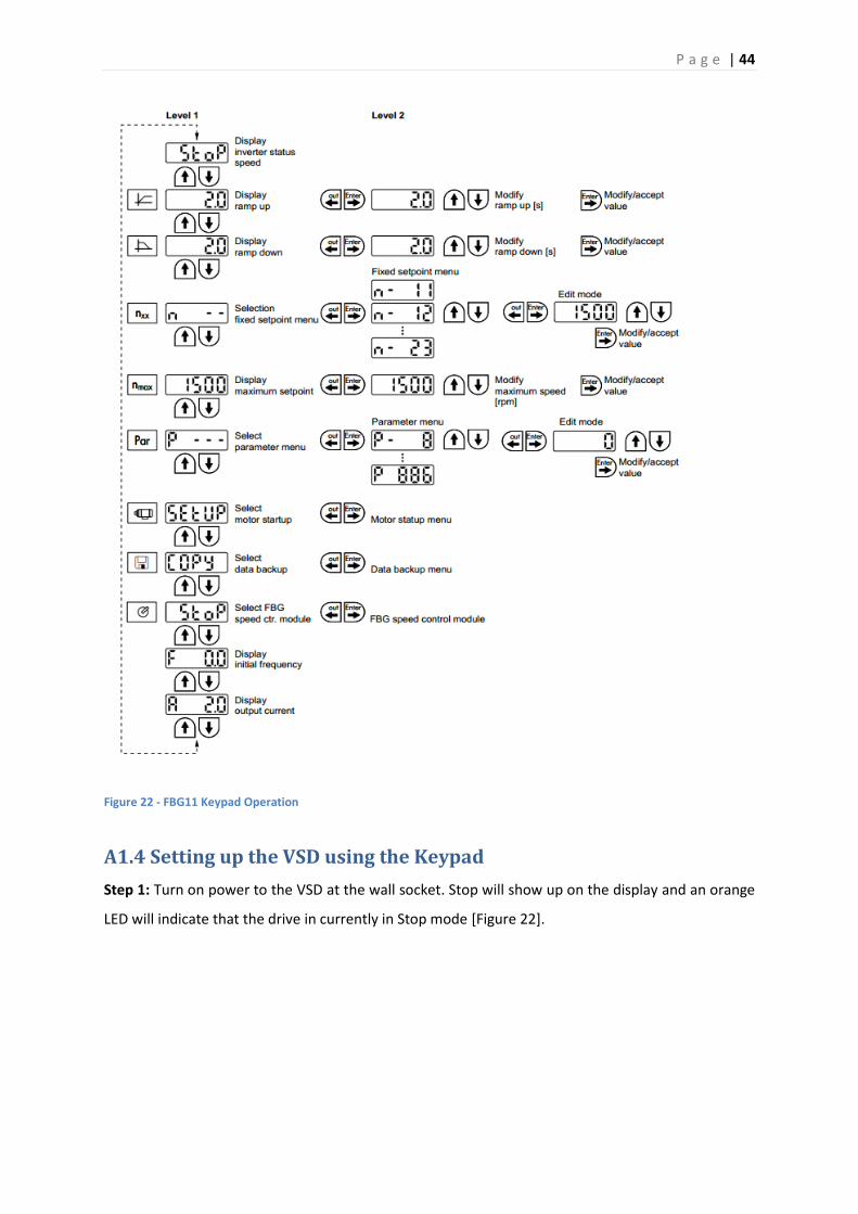
P a g e | 44
Figure 22 - FBG11 Keypad Operation
A1.4 Setting up the VSD using the Keypad
Step 1: Turn on power to the VSD at the wall socket. Stop will show up on the display and an orange
LED will indicate that the drive in currently in Stop mode [Figure 22].

P a g e | 45
Figure 23 - Stop Mode
Step 2: Use the Up and Down arrows to cycle through the top level parameters, enter in the desired
ramping values using the arrow keys to navigate between parameters [Figure 24]. Use the Enter key
to select the parameter you want to modify.
Figure 24 - Keypad Parameters
Step 3: Enter Setup to input the motor specifications. The motor specifications can be found on the
motor name plate [Figure 28]. In the Motor Setup menu enter in the data from Table 14. Figure 28
shows the SEW motor nameplate while Table 14 presents the motors specifications in table form.
Figure 26 provides a detailed illustration of how to enter in the motor specifications.
Figure 25 - Motor Setup

P a g e | 46
Specification Value
Motor SEW
Mode UF
Rated Power (kW) 0.18
Rated Voltage - 50Hz (V) 380-415 (Υ)
Hertz 50
RPM 1320
4Q Operation Yes
Multi 1
Table 14 - SEW Motor Specifications
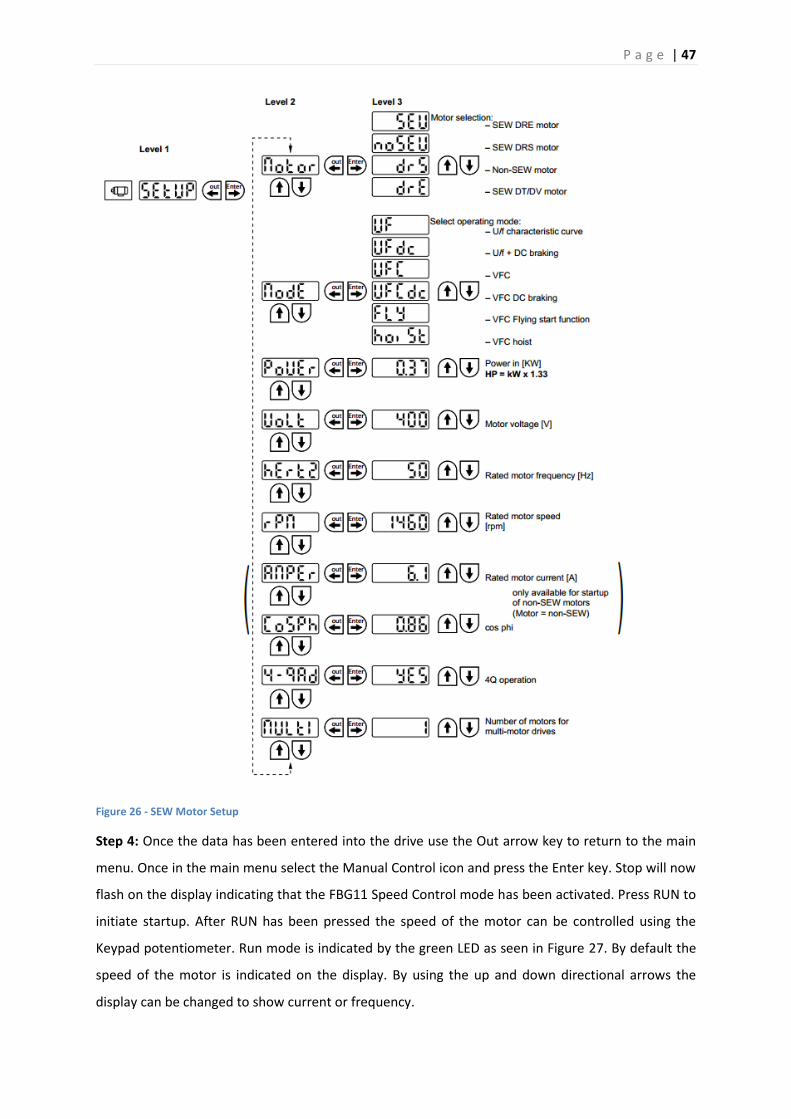
P a g e | 47
Figure 26 - SEW Motor Setup
Step 4: Once the data has been entered into the drive use the Out arrow key to return to the main
menu. Once in the main menu select the Manual Control icon and press the Enter key. Stop will now
flash on the display indicating that the FBG11 Speed Control mode has been activated. Press RUN to
initiate startup. After RUN has been pressed the speed of the motor can be controlled using the
Keypad potentiometer. Run mode is indicated by the green LED as seen in Figure 27. By default the
speed of the motor is indicated on the display. By using the up and down directional arrows the
display can be changed to show current or frequency.

P a g e | 48
Figure 27 - Run Mode
Note: To stop the drive at any point press the STOP/Reset button.
When exiting Manual control mode press STOP/Reset to stop the drive then press the Out arrow key
to return to the main menu.
Step 5: The direction of rotation can be set by storing either 0, 1 or 2 with 0 as the default in the
parameter P122 [Table 15]. To store a value in P122 - select Parameter from the main menu on the
Keypad and press the Enter key- to cycle through the available parameters use the Up and Down
arrows, select P122 and press the Enter key. Then use the Up and Down arrows to select the desired
value to be stored, use the Enter key to confirm the selection. Use the Out key to return to the main
menu.
Parameter Parameter Value Description
P122 0 (Default) Unipolar - CW1 0...nmax
1 Unipolar - CCW2 0...nmax
2 Bipolar - CW1 + CCW2 -nmax...nmax
1 Clockwise
2 Counter Clockwise
Table 15 - Rotational Direction Parameter P122

P a g e | 49
Figure 28 shows the SEW motor nameplate. This nameplate displays the motor specifications such as
rated voltage, power current and speed.
Figure 28 - SEW R17 DR63M4 Motor Nameplate
Table 16 presents much of the information contained in the motor nameplate in an easy to read
table.
Figure 29 - SEW Motor Nameplate
Specification Value
Model R17 DR63M4
Rated Power (kW) 0.18/0.18 S1
Rated Voltage - 50Hz (V) 220-240Δ/380-415Υ
Rated Voltage - 60Hz (V) 240-266Δ/415-460Υ
RPM 1320/30 / 1620/37
Cos φ 0.78
Rated Current - 50Hz (A) 0.96/0.55
Rated Current - 60Hz (A) 0.87/0.50
Gear Reduction Ratio 44.81
Table 16 - SEW Motor Nameplate Specifications

P a g e | 50
A2.0 You and Your VSD Tutorial 2
A2.1 Overview
This document has been designed to provide instruction on how to setup and configure the VSD for
operation on RS-485, SBus and Profibus using MOVITOOLS MotionStudio over the RS-485 link.
A2.2 Resources
SEW MOVITRAC B VSD
SEW R17 DR63M4 (motor connected to the VSD)
MOVITOOLS MotionStudio Software
SEW RS-232 to RS-485 Converter
SEW UOIH11B Gateway
SEW FBG11B Keypad
Siemens S7 314C-2DP PLC
Profibus Connection

P a g e | 51
A2.3 Startup Using MOVITOOLS MotionStudio
Step 1: Open MOVITOOLS MotionStudio.
Step 2: Right click on Network and click Scan. This will detect any device connected to the network.
Step 3: Once the device has been detected it is then possible to configure the attached unit. This is
done by right clicking on the device and selecting configure unit.

P a g e | 52
A2.4 Setting up the Gateway and VSD
Firstly wire a 24V switch into DI01. When a 24V signal is present at DI01 it will enable the VSD. This
switch is needed to enable the VSD after a fault has occurred. Note that the FSC11B card will have to
be removed to wire-in the switch.
Figure 30 details the SBus connection between the Gateway and VSD. Tables 17 and 18 provide
details on the terminal functionality for the VSD and Gateway respectively.
The end result should resemble that shown in Figure 31.
Figure 30 - Connecting SBus
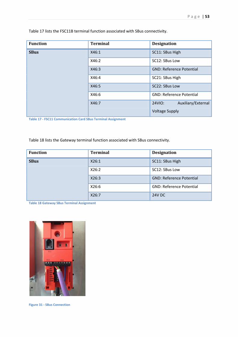
P a g e | 53
Table 17 lists the FSC11B terminal function associated with SBus connectivity.
Function Terminal Designation
SBus X46:1 SC11: SBus High
X46:2 SC12: SBus Low
X46:3 GND: Reference Potential
X46:4 SC21: SBus High
X46:5 SC22: SBus Low
X46:6 GND: Reference Potential
X46:7 24VIO: Auxiliary/External
Voltage Supply
Table 17 - FSC11 Communication Card SBus Terminal Assignment
Table 18 lists the Gateway terminal function associated with SBus connectivity.
Function Terminal Designation
SBus X26:1 SC11: SBus High
X26:2 SC12: SBus Low
X26:3 GND: Reference Potential
X26:6 GND: Reference Potential
X26:7 24V DC
Table 18 Gateway SBus Terminal Assignment
Figure 31 - SBus Connection

P a g e | 54
Once the VSD and Gateway have been connected by the SBus cable the Gateway address needs to
be set using the dip switches located on the front section of the device. Figure 32 illustrates how to
set the address. Make sure to set AS to the ON position, this allows diagnostics to be run from
MotionStudio.
Figure 32 - Gateway Addressing Using Dip Switches
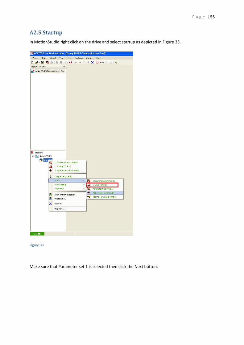
P a g e | 55
A2.5 Startup
In MotionStudio right click on the drive and select startup as depicted in Figure 33.
Figure 33
Make sure that Parameter set 1 is selected then click the Next button.
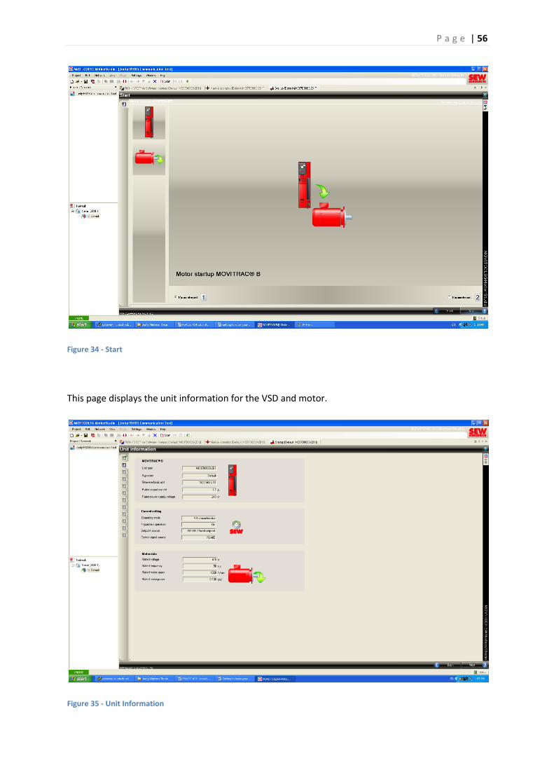
P a g e | 56
Figure 34 - Start
This page displays the unit information for the VSD and motor.
Figure 35 - Unit Information
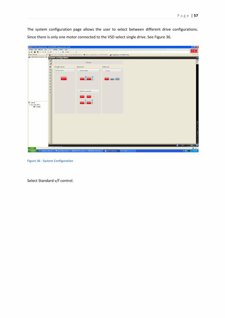
P a g e | 57
The system configuration page allows the user to select between different drive configurations.
Since there is only one motor connected to the VSD select single drive. See Figure 36.
Figure 36 - System Configuration
Select Standard v/f control.
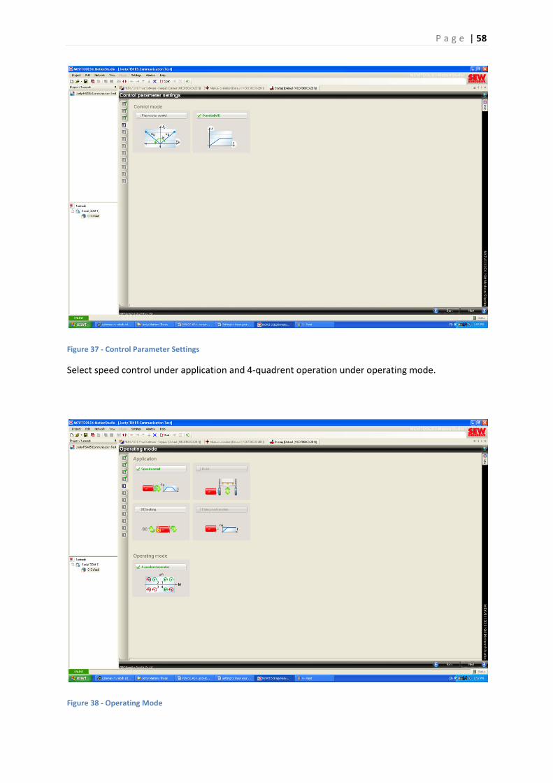
P a g e | 58
Figure 37 - Control Parameter Settings
Select speed control under application and 4-quadrent operation under operating mode.
Figure 38 - Operating Mode
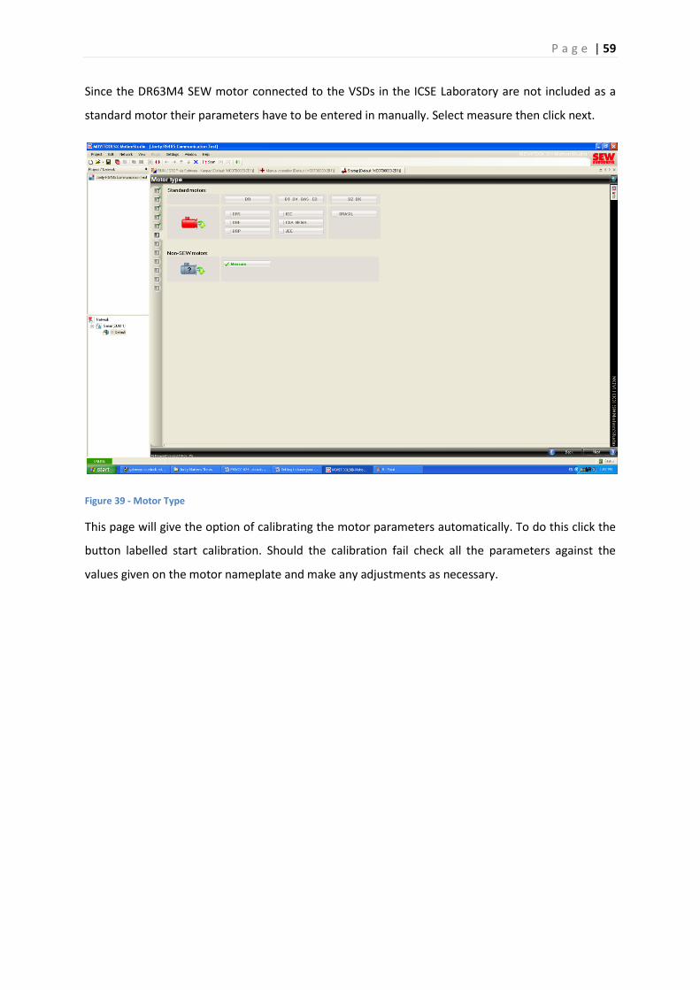
P a g e | 59
Since the DR63M4 SEW motor connected to the VSDs in the ICSE Laboratory are not included as a
standard motor their parameters have to be entered in manually. Select measure then click next.
Figure 39 - Motor Type
This page will give the option of calibrating the motor parameters automatically. To do this click the
button labelled start calibration. Should the calibration fail check all the parameters against the
values given on the motor nameplate and make any adjustments as necessary.
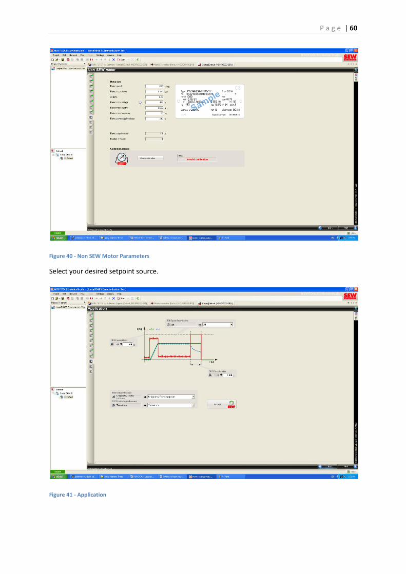
P a g e | 60
Figure 40 - Non SEW Motor Parameters
Select your desired setpoint source.
Figure 41 - Application
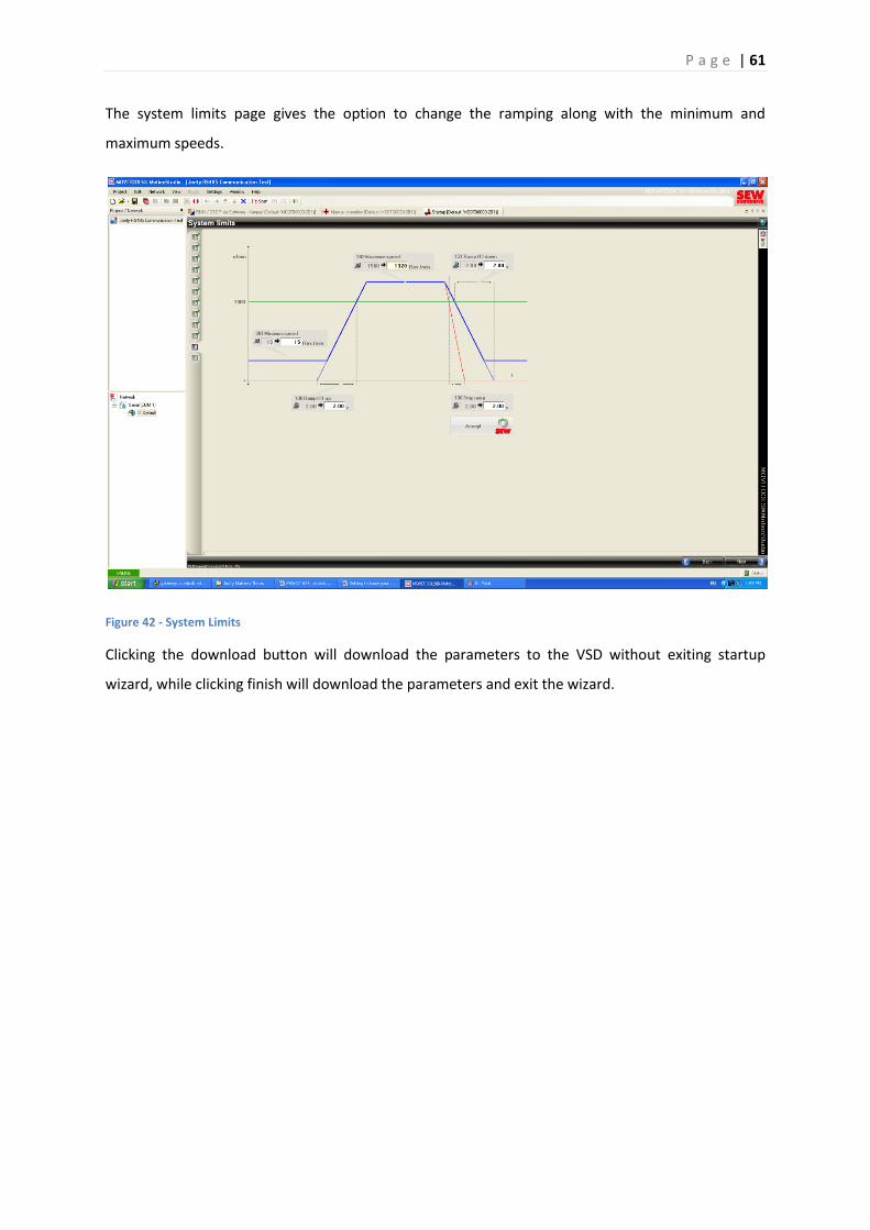
P a g e | 61
The system limits page gives the option to change the ramping along with the minimum and
maximum speeds.
Figure 42 - System Limits
Clicking the download button will download the parameters to the VSD without exiting startup
wizard, while clicking finish will download the parameters and exit the wizard.
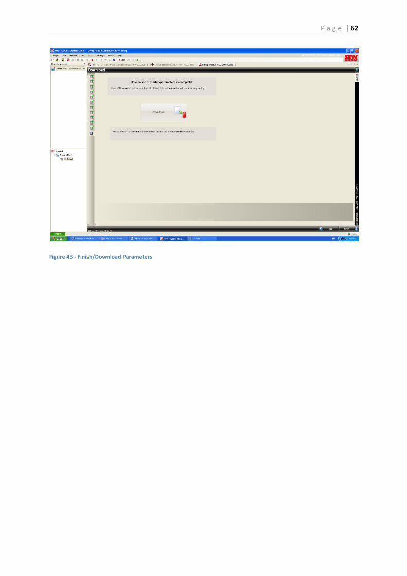
P a g e | 62
Figure 43 - Finish/Download Parameters
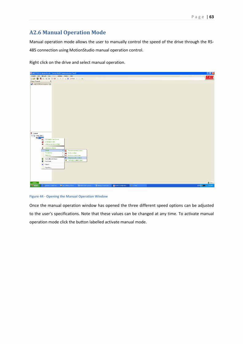
P a g e | 63
A2.6 Manual Operation Mode
Manual operation mode allows the user to manually control the speed of the drive through the RS-
485 connection using MotionStudio manual operation control.
Right click on the drive and select manual operation.
Figure 44 - Opening the Manual Operation Window
Once the manual operation window has opened the three different speed options can be adjusted
to the user's specifications. Note that these values can be changed at any time. To activate manual
operation mode click the button labelled activate manual mode.
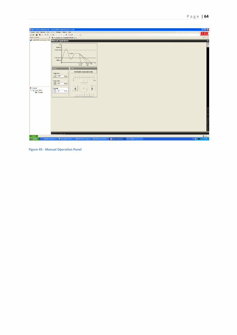
P a g e | 64
Figure 45 - Manual Operation Panel
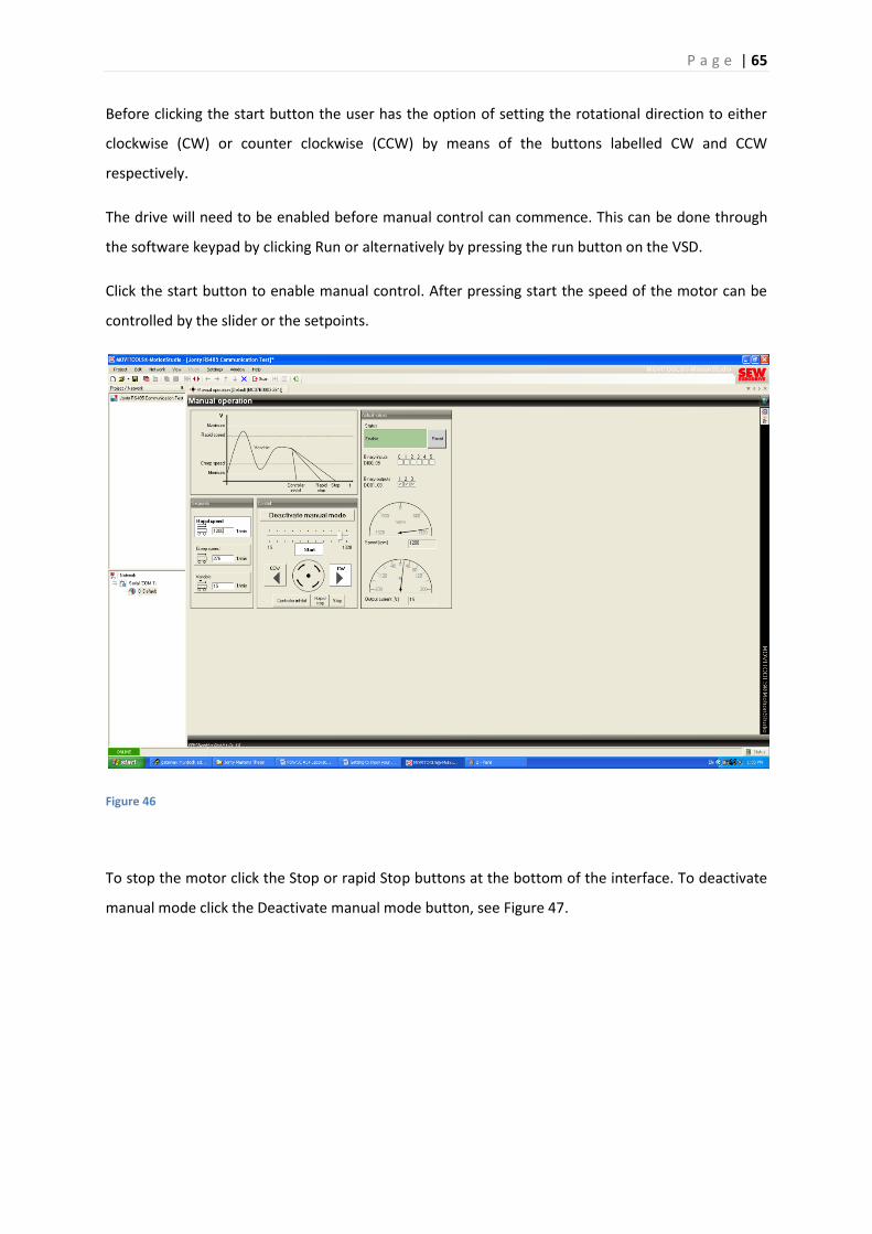
P a g e | 65
Before clicking the start button the user has the option of setting the rotational direction to either
clockwise (CW) or counter clockwise (CCW) by means of the buttons labelled CW and CCW
respectively.
The drive will need to be enabled before manual control can commence. This can be done through
the software keypad by clicking Run or alternatively by pressing the run button on the VSD.
Click the start button to enable manual control. After pressing start the speed of the motor can be
controlled by the slider or the setpoints.
Figure 46
To stop the motor click the Stop or rapid Stop buttons at the bottom of the interface. To deactivate
manual mode click the Deactivate manual mode button, see Figure 47.
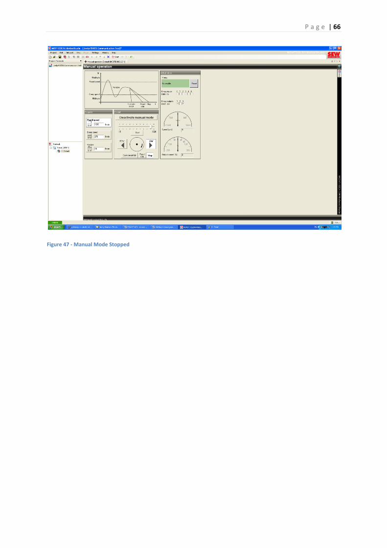
P a g e | 66
Figure 47 - Manual Mode Stopped
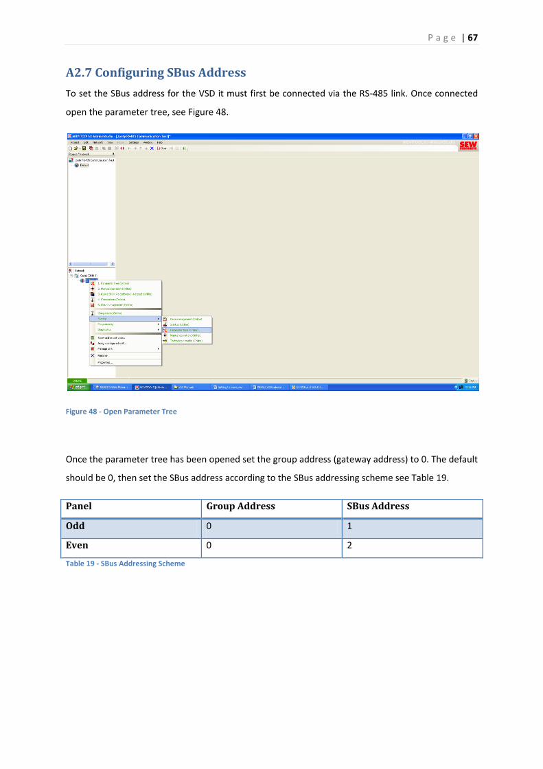
P a g e | 67
A2.7 Configuring SBus Address
To set the SBus address for the VSD it must first be connected via the RS-485 link. Once connected
open the parameter tree, see Figure 48.
Figure 48 - Open Parameter Tree
Once the parameter tree has been opened set the group address (gateway address) to 0. The default
should be 0, then set the SBus address according to the SBus addressing scheme see Table 19.
Panel Group Address SBus Address
Odd 0 1
Even 0 2
Table 19 - SBus Addressing Scheme
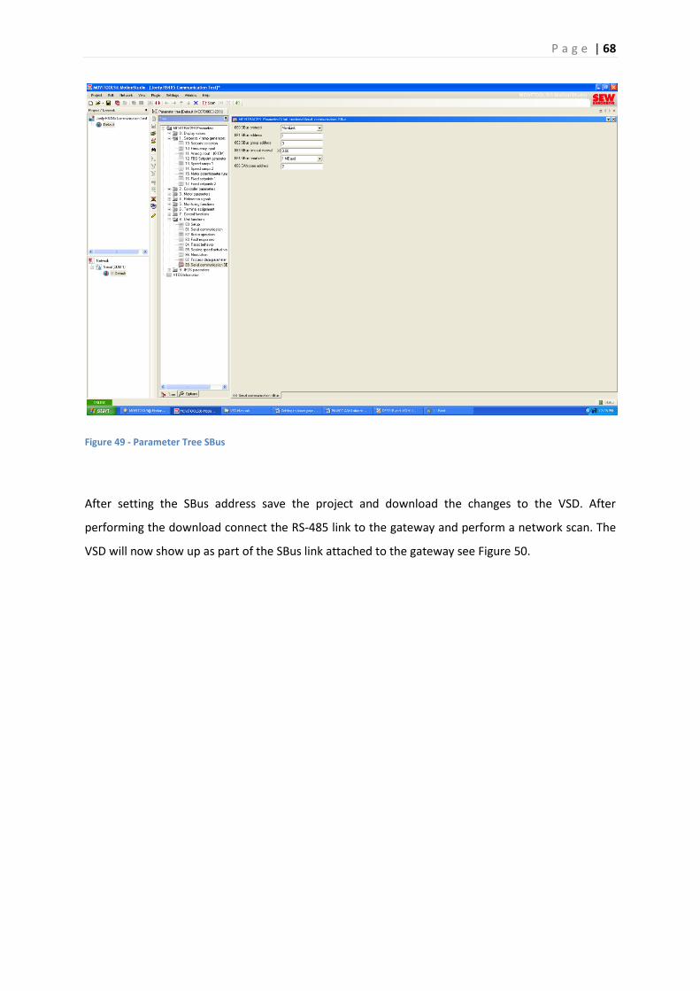
P a g e | 68
Figure 49 - Parameter Tree SBus
After setting the SBus address save the project and download the changes to the VSD. After
performing the download connect the RS-485 link to the gateway and perform a network scan. The
VSD will now show up as part of the SBus link attached to the gateway see Figure 50.
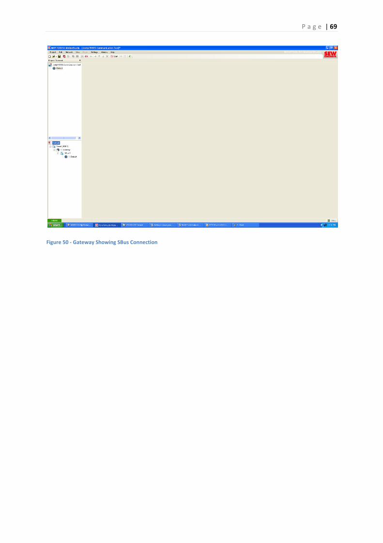
P a g e | 69
Figure 50 - Gateway Showing SBus Connection
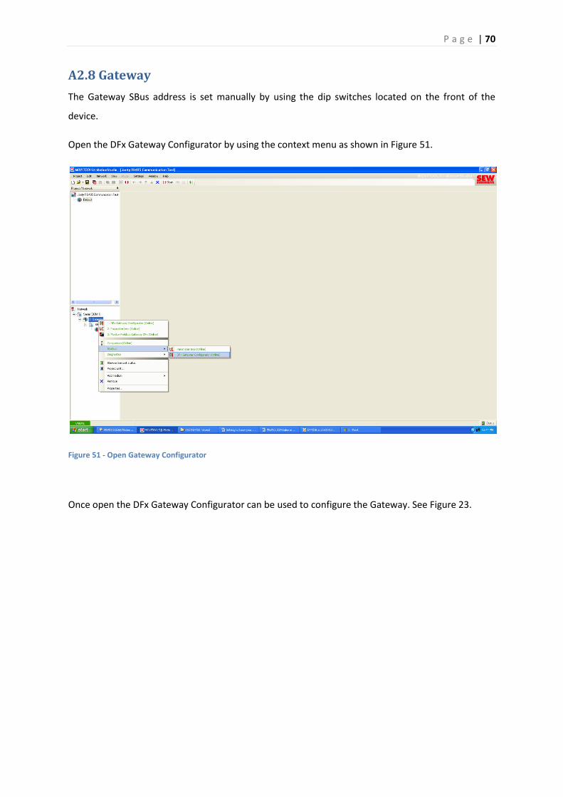
P a g e | 70
A2.8 Gateway
The Gateway SBus address is set manually by using the dip switches located on the front of the
device.
Open the DFx Gateway Configurator by using the context menu as shown in Figure 51.
Figure 51 - Open Gateway Configurator
Once open the DFx Gateway Configurator can be used to configure the Gateway. See Figure 23.

P a g e | 71
Figure 52 -Configuring the Gateway
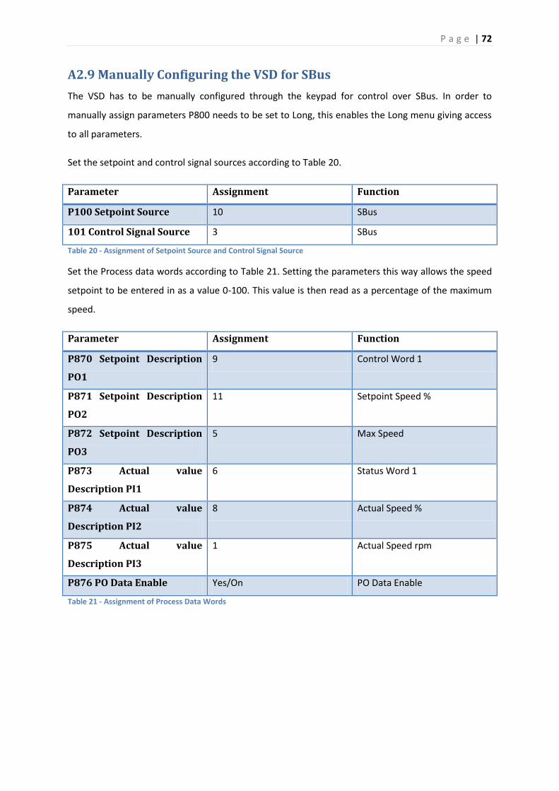
P a g e | 72
A2.9 Manually Configuring the VSD for SBus
The VSD has to be manually configured through the keypad for control over SBus. In order to
manually assign parameters P800 needs to be set to Long, this enables the Long menu giving access
to all parameters.
Set the setpoint and control signal sources according to Table 20.
Parameter Assignment Function
P100 Setpoint Source 10 SBus
101 Control Signal Source 3 SBus
Table 20 - Assignment of Setpoint Source and Control Signal Source
Set the Process data words according to Table 21. Setting the parameters this way allows the speed
setpoint to be entered in as a value 0-100. This value is then read as a percentage of the maximum
speed.
Parameter Assignment Function
P870 Setpoint Description
PO1
9 Control Word 1
P871 Setpoint Description
PO2
11 Setpoint Speed %
P872 Setpoint Description
PO3
5 Max Speed
P873 Actual value
Description PI1
6 Status Word 1
P874 Actual value
Description PI2
8 Actual Speed %
P875 Actual value
Description PI3
1 Actual Speed rpm
P876 PO Data Enable Yes/On PO Data Enable
Table 21 - Assignment of Process Data Words
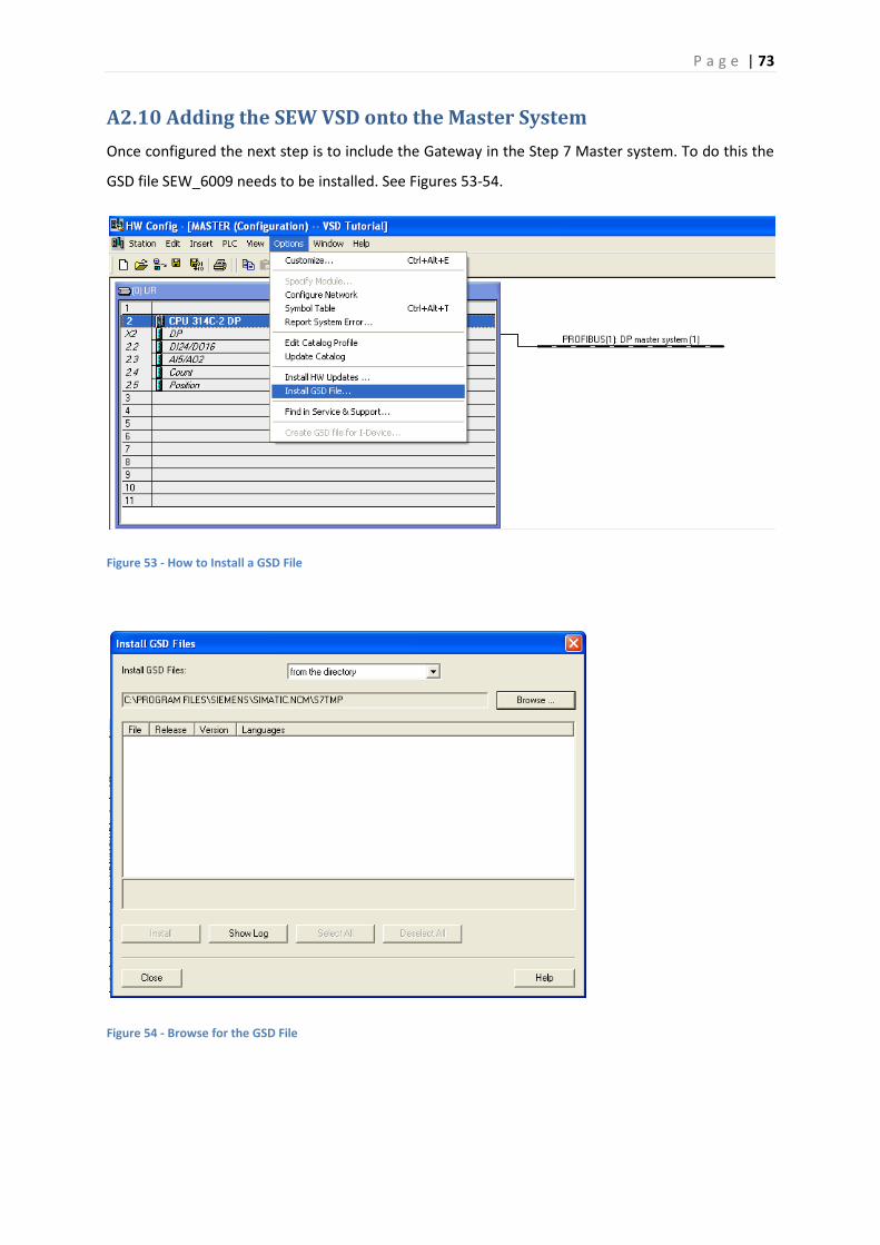
P a g e | 73
A2.10 Adding the SEW VSD onto the Master System
Once configured the next step is to include the Gateway in the Step 7 Master system. To do this the
GSD file SEW_6009 needs to be installed. See Figures 53-54.
Figure 53 - How to Install a GSD File
Figure 54 - Browse for the GSD File
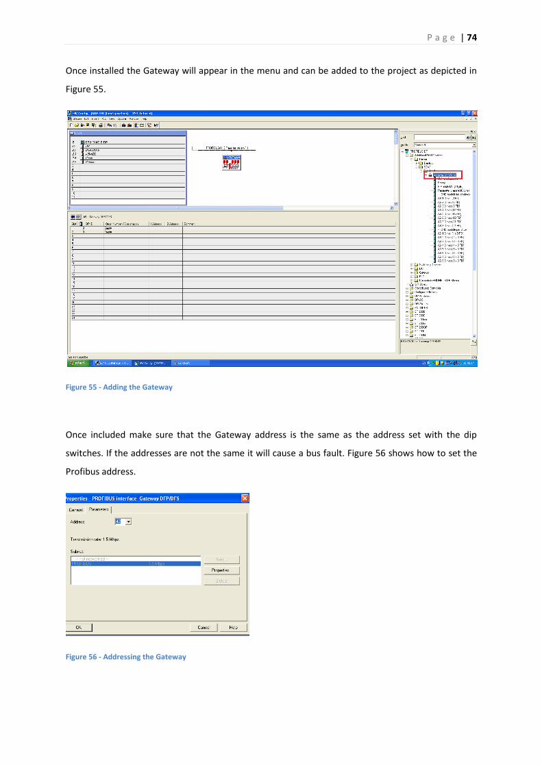
P a g e | 74
Once installed the Gateway will appear in the menu and can be added to the project as depicted in
Figure 55.
Figure 55 - Adding the Gateway
Once included make sure that the Gateway address is the same as the address set with the dip
switches. If the addresses are not the same it will cause a bus fault. Figure 56 shows how to set the
Profibus address.
Figure 56 - Addressing the Gateway
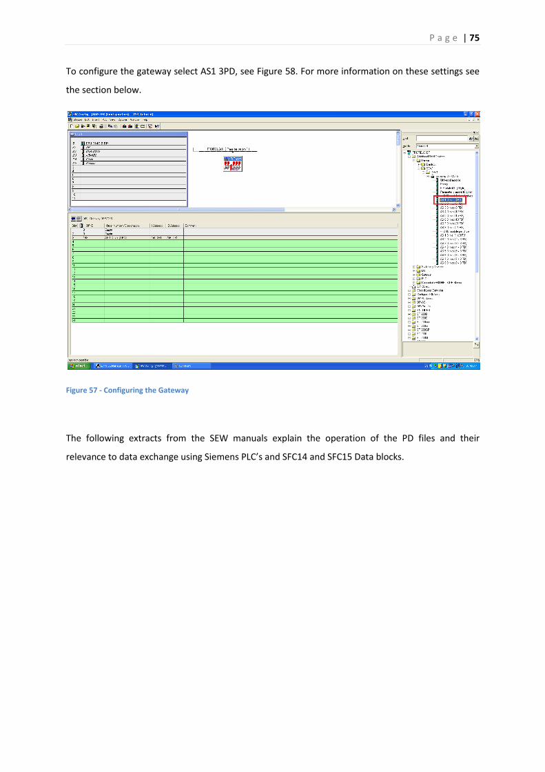
P a g e | 75
To configure the gateway select AS1 3PD, see Figure 58. For more information on these settings see
the section below.
Figure 57 - Configuring the Gateway
The following extracts from the SEW manuals explain the operation of the PD files and their
relevance to data exchange using Siemens PLC’s and SFC14 and SFC15 Data blocks.
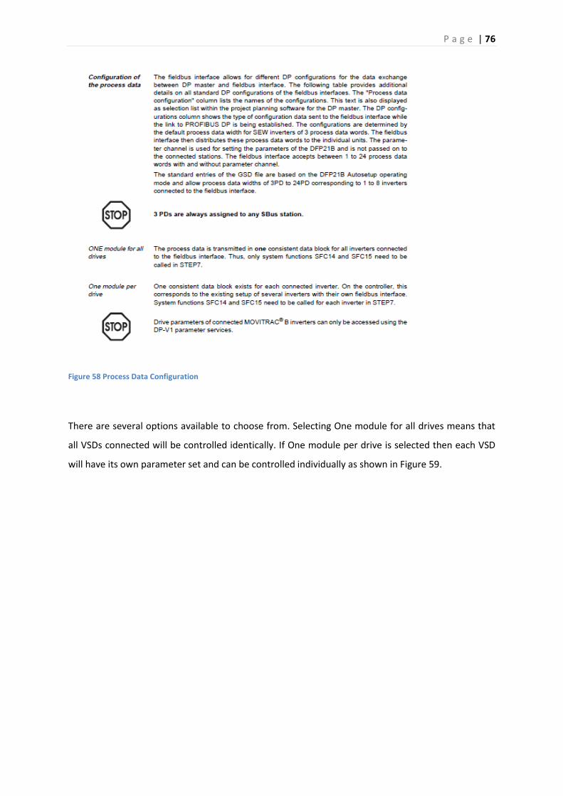
P a g e | 76
Figure 58 Process Data Configuration
There are several options available to choose from. Selecting One module for all drives means that
all VSDs connected will be controlled identically. If One module per drive is selected then each VSD
will have its own parameter set and can be controlled individually as shown in Figure 59.
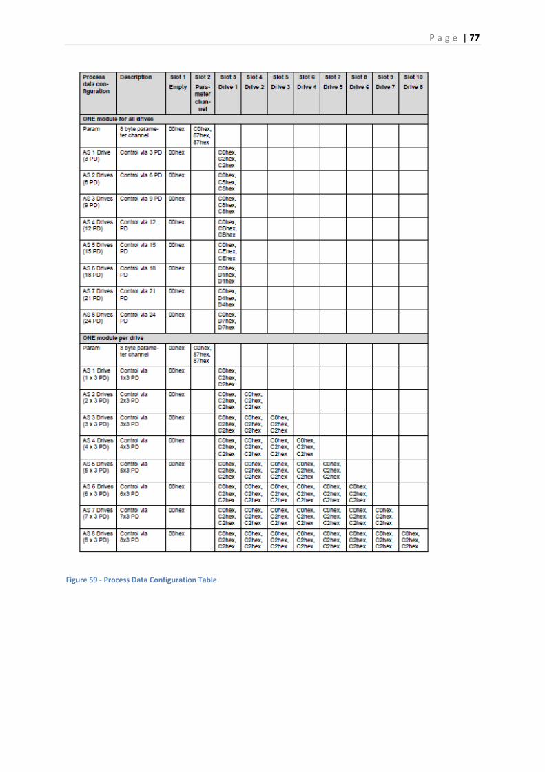
P a g e | 77
Figure 59 - Process Data Configuration Table
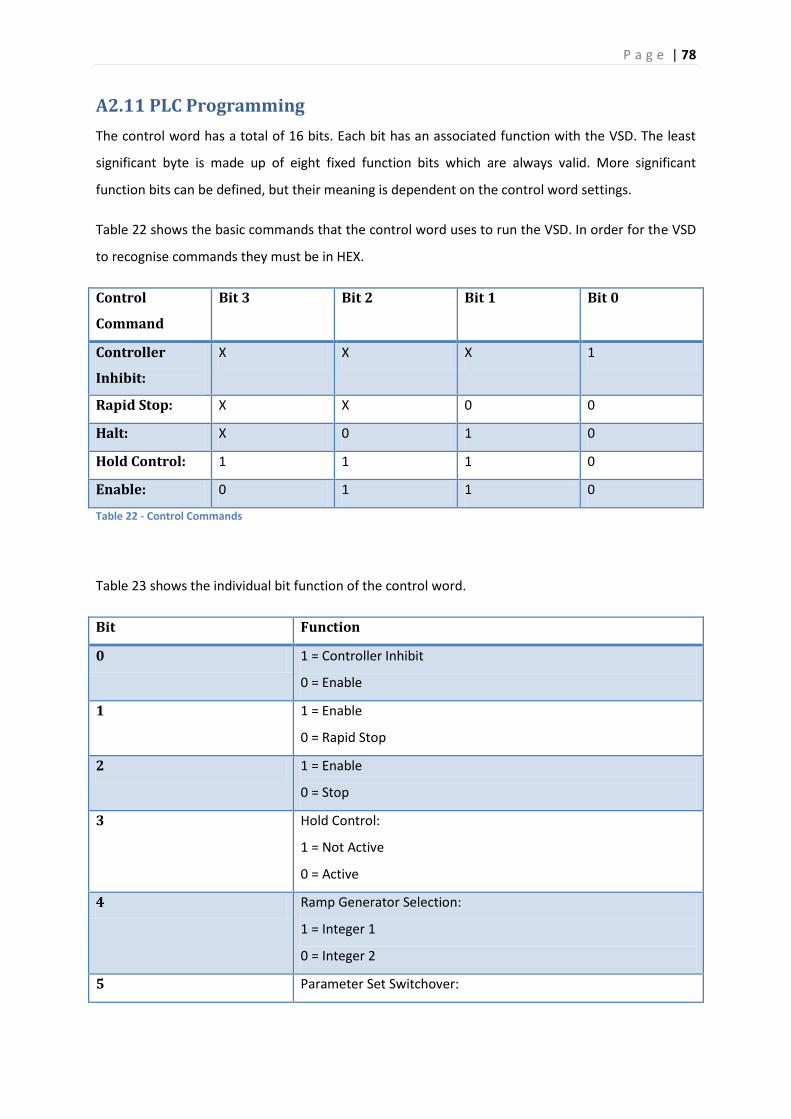
P a g e | 78
A2.11 PLC Programming
The control word has a total of 16 bits. Each bit has an associated function with the VSD. The least
significant byte is made up of eight fixed function bits which are always valid. More significant
function bits can be defined, but their meaning is dependent on the control word settings.
Table 22 shows the basic commands that the control word uses to run the VSD. In order for the VSD
to recognise commands they must be in HEX.
Control
Command
Bit 3 Bit 2 Bit 1 Bit 0
Controller
Inhibit:
X X X 1
Rapid Stop: X X 0 0
Halt: X 0 1 0
Hold Control: 1 1 1 0
Enable: 0 1 1 0
Table 22 - Control Commands
Table 23 shows the individual bit function of the control word.
Bit Function
0 1 = Controller Inhibit
0 = Enable
1 1 = Enable
0 = Rapid Stop
2 1 = Enable
0 = Stop
3 Hold Control:
1 = Not Active
0 = Active
4 Ramp Generator Selection:
1 = Integer 1
0 = Integer 2
5 Parameter Set Switchover:

P a g e | 79
1 = Parameter Set 2
0 = Parameter Set 1
6 Reset:
1 = Reset Pending Fault
0 = Not Active
7 Reserved
8
Dependent on Control Word Settings
9
10
11
12
13
14
15
Table 23 - Control Word - Basic Control Block
Figure 60 shows the PLC code used to write the Run and Stop commands in HEX format to a memory
word. A move block is needed because the address in the VSD is one word in length. Note W#16#2 is
the Stop command and W#16#6 is the Enable command.

P a g e | 80
Figure 60 - Assigning Run and Stop Commands for the VSD
The next step is to write a section of code to set the maximum speed of the VSD. See Figure 61
Network 4. MD42 serves as the input for the maximum speed, while 1320 rpm is the absolute
maximum speed for the VSD. The output from the DIV_R block is a number between 0 and 1. The
number 6600 is the number that the VSD interprets as 1320 rpm. This number just happens to be
five times the maximum speed. The Floor block is used to convert a real number into an integer.
Lastly the Move block is used to move the bottom two words from MD54 to MW6. The reason for
this will become apparent shortly.
The method used to control the speed of the VSD is very similar to the one for setting the maximum
speed. The only differences being that the input is read in as a percentage and the scaling number
16384 (HEX 4000) is interpreted as 100% by the VSD. The end result is stored in MW4. This is
illustrated in Figure 32 Network 5.
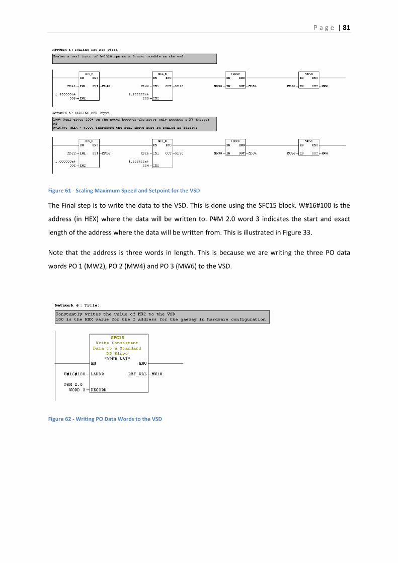
P a g e | 81
Figure 61 - Scaling Maximum Speed and Setpoint for the VSD
The Final step is to write the data to the VSD. This is done using the SFC15 block. W#16#100 is the
address (in HEX) where the data will be written to. P#M 2.0 word 3 indicates the start and exact
length of the address where the data will be written from. This is illustrated in Figure 33.
Note that the address is three words in length. This is because we are writing the three PO data
words PO 1 (MW2), PO 2 (MW4) and PO 3 (MW6) to the VSD.
Figure 62 - Writing PO Data Words to the VSD