form finding for cable-stayed and extradosed bridges
TRANSCRIPT

i
FORM FINDING FOR CABLE-STAYED AND
EXTRADOSED BRIDGES
vorgelegt von
Dipl.-Ing.
El Araby El Shenawy
aus Ägypten
Von der Fakultät VI – Planen Bauen Umwelt
der Technischen Universität Berlin
zur Erlangung des akademischen Grades
Doktor der Ingenieurwissenschaften
Dr.-Ing.
genehmigte Dissertation
Promotionsausschuss:
Prof.Dr.-Ing. Karsten Geißler
Gutachter: Prof. Dr. sc. techn. Mike Schlaich
Gutachter: Dr.-Ing. Akio Kasuga
Tag der wissenschaftlichen Aussprache: 05.12.2012
Berlin 2013
D 83

ii

iii
AKNOWLEDGMENTS
I would like to thank and express my profound gratitude to my supervisor Prof. Dr. sc. tech. Mike Schlaich from TU-Berlin “Technische Universität Berlin” for his encouragement, support and guidance.
I also take this opportunity to express my gratitude to Dr. Akio Kasuga for his kind advice and cordial support.
I am indebted to staff members of the “Conceptual and Structural Design Department” at TU-Berlin. I am grateful for their cooperation.
I wish also to express my thanks for all the great opportunities and professional development I have had at “Schlaich Bergerman und Partner”, ''Campenon Bernard SGE'' and “Dar Al-Handasah Consultants”.
I thank the ALMIGHTY, my parents and family.
El Araby El Shenawy

iv

v
ABSTRACT
The form finding for cable supported structures (roof structures or bridge structures) means
simply the definition of the cable forces under dead load. The form finding method for
conventional cable-stayed bridges with concrete-only or steel-only deck cross sections is well
established. In this research work the common methods used for the determination of the stay
cable forces under dead load will be discussed. It will be shown that these methods will not lead
to the desired stay cable forces or the desired bridge alignment in case of cable-stayed bridges
with composite decks.
A new method will be presented for the form finding of cable-stayed bridges with composite
(steel/concrete) or (concrete/concrete) deck cross sections if the composite section is planned to
be constructed in two stages. For the establishment of the new method for the form finding of
cable-stayed bridges with composite decks, the following effects will be investigated:
- The ratio between the moment of inertia of the first part of the composite section and the total
moment of inertia of the composite section and the vertical shift between the center of gravity
of the first part of the composite section and the center of gravity of the total composite section.
- The time dependent forces due to creep and shrinkage.
Further, the study carried out for the form finding of conventional cable-stayed bridges will be
extended to additionally present a new method for the form finding of extradosed bridges. The
extradosed bridges emerged in the last two decades as a promising structural system to
effectively and economically bridge spans ranging between 100 and 200 m. For such spans the
prestressed box girder bridges require deep and heavy deck cross section. Further, conventional
cable-stayed bridges with spans less than 200m appear to be not economical. The researches and
the survey of the extradosed bridges built so far, indicate that there is still a need to establish a
consistent method for the definition of the stay cable forces under dead load. The method
established in this research work for this purpose, includes also solutions to determine and handle
the required internal and/or external prestressing within the deck cross section. The proposed
method for the form finding of the extradosed bridges is suitable for use for bridges with
concrete, steel or composite sections. For extradosed bridges with a concrete deck, a combination
of the stay cable forces and the prestressing forces inside the deck section may be targeted to
eliminate the bending moment along the entire length of the deck under dead load.

vi
KURZFASSUNG
Die Formfindung für Seilkonstruktionen (Dachkonstruktionen oder Brückenbauwerke) bedeutet
im vereinfachten Sinne die Definition der Seilkräfte für das Tragwerk unter Eigengewicht.
Die gängigen Formfindungsverfahren für konventionelle Schrägseilbrücken mit Fahrbahn-
überbauten aus Beton oder Stahl haben sich bereits etabliert. Die üblichen Methoden, die zur
Ermittlung der Seilkräfte unter Eigengewicht verwendet werden, werden in dieser Forschungs-
arbeit diskutiert. Es wird gezeigt, dass für Brücken aus Verbundquerschnitten, diese Methoden
weder zu den gewünschten Seilkräften noch zu der gewünschten Brückengeometrie führen. Für
Schrägseilbrücken aus Verbundquerschnitten, die in zwei Bauabschnitten (BA) hergestellt
werden, wird in dieser Forschungsarbeit ein neues Verfahren für die Berechnung der Seilkräfte
unter Eigengewicht vorgestellt. Für diese neue Methode werden die folgenden Faktoren
untersucht:
- Das Verhältnis zwischen dem Trägheitsmoment des Teilquerschnitts (erster BA) und dem
Trägheitsmoment des Gesamtquerschnitts (zweiter BA) und der vertikale Abstand zwischen
dem Schwerpunkt des Teilquerschnitts (erster BA) und dem Schwerpunkt des
Gesamtquerschnitts (zweiter BA).
- Die Zeitabhängigen Kräfte infolge Kriechen und Schwinden.
In dieser Arbeit wird auch eine neue Methode zur Formfindung von Extradosed Brücken
vorgestellt. Die Extradosed Brücken entstanden in den letzten zwei Jahrzehnten als ein effektives
und wirtschaftliches Brückentragwerk für Spannweiten zwischen 100 und 200 m. Für solche
Spannweiten erfordern die vorgespannten Hohlkastenbrücken sehr große Überbauhöhen. Darüber
hinaus scheinen die konventionellen Schrägseilbrücken mit Spannweiten weniger als 200 m
unwirtschaftlich zu sein. Die Forschungen und die Untersuchungen der bisher gebauten
Extradosed Brücken zeigen, dass eine konsistente Methode zur Definition der Seilkräfte unter
Eigengewicht noch nicht vorhanden ist. Die zu diesem Zweck in dieser Arbeit vorgestellte
Methode eignet sich für Überbauten aus Beton-, Stahl- und Verbundquerschnitten. Außerdem
werden Methoden zur Bestimmung der erforderlichen internen und externen Vorspannung
empfohlen. Für Extradosed Brücken mit Fahrbahnüberbauten aus Beton können die
Biegemomente unter Eigengewicht entlang der gesamten Brückenlänge, durch das aufeinander
abstimmen der Seilkräfte und der Vorspannkräfte im Überbau eliminiert werden.

vii
TABLE OF CONTENTS
1- INTRODUCTION ..................................................................................................................... 1
2- CABLE-STAYED BRIDGES IN GENERAL ............................................................................ 5
2-1 Types of stay cables ............................................................................................................ 5
2-1-1 Parallel-Bar Cables ..................................................................................................... 6
2-1-2 Locked Coil Strand Cables ......................................................................................... 6
2-1-3 Parallel Wire Cables ................................................................................................... 7
2-1-4 Parallel Strand Cables .............................................................................................. 11
2-1-5 Anchorages of Stay Cables at Deck and Tower head Levels ................................... 16
2-2 Possible structural systems for conventional cable-stayed bridges (supporting system
between the tower and the deck & between the deck and the end support) ...................... 22
3- PREVIOUS RESEARCH WORKS FOR CABLES-STAYED BRIDGES RELATED TO
THE RECOMMENDED STAY CABLE FORCES UNDER DEAD LOAD ....................... 29
3-1 The continuous beam method ............................................................................................. 29
3-1-1 Effect of creep on a simple concrete beam ............................................................... 31
3-1-2 Effect of creep on a continuous concrete beam ........................................................ 34
3.2 The “bending moment envelope for live loads” method .................................................. 42
3.3 The method of influence matrix for stay cable forces ...................................................... 44
4- CONSTRUCTION ANALYSIS OF BRIDGES WITH COMPOSITE DECKS ...................... 51
4-1 Time dependent effects on bridge structures with composite decks ................................ 52
4-1-1 Time dependent effect due to vertical loads (Type I) .............................................. 52
4-1-2 Additional time dependent effect in case of a composite deck (Type II) ................. 53
4-2 Construction stage analysis of cable-stayed bridges with concrete-only or steel-only deck
section ................................................................................................................................ 57
4-3 Construction stage analysis for cable-stayed bridges with composite deck sections ........ 58
4-3-1 Construction of the composite section in one single stage (Construction method no.
1) ............................................................................................................................... 58
4-3-2 Construction of the composite cross section in two stages (Construction methods
nos. 2,3 and 4) .......................................................................................................... 59
4-3-3 Application of the construction methods 2,3 and 4 on a simple cables supported
beam ......................................................................................................................... 66

viii
4-3-4 Proposed modification for the construction method no. 4 (construction method no. 5)
.................................................................................................................................. 72
4-3-5 Application of the construction method no. (4) or (5) on cable-stayed bridges with
composite deck sections ........................................................................................... 74
5- EXTRADOSED BRIDGES ..................................................................................................... 77
5-1 Common configuration of previously constructed extradosed bridges ............................ 79
5-2 Design of stay cables for conventional cable-stayed bridges and extradosed bridges ..... 80
5-3 Structural system for extradosed bridges ......................................................................... 85
6- PROPOSED METHOD FOR THE DETERMINATION OF THE STAY CABLE FORCES
UNDER DEAD LOAD FOR EXTRADOSED BRIDGES ...................................................... 89
6-1 Method of the calculation of the desired equivalent vertical stay cable forces WC .......... 90
6-2 Proposed method for handling the prestressing forces for extradosed bridges ............... 100
6-2-1 Use of concordant prestressing cable profiles for continuous beams [Lin and Burns
1989] [Leonhardt 2004] ......................................................................................... 100
6-2-2 Possible use of concordant cable profiles for the extradosed bridges .................... 103
6-2-3 Handling prestressing configurations other than concordant profiles .................... 105
6-2-4 Preliminary design .................................................................................................. 113
6-3 Commercial consideration related to the use of the stay cables and the concordant
prestressing cables ........................................................................................................... 115
7- POSSIBLE CONSTRUCTION METHODS FOR THE EXTRADOSED BRIDGES ........... 117
7-1 Fabrication of Precast Segments ...................................................................................... 118
7-2 Methods of erection of precast segments ........................................................................ 120
7-2-1 Erection of deck with cross section consisting of three precast segments ............. 123
7-3 Proposal for the construction of extradosed bridges ........................................................ 126
8- CONCLUSIONS AND RECOMMENDATIONS ................................................................. 131
8-1 Conclusions ..................................................................................................................... 131
8-2 Recommendations ........................................................................................................... 132
REFERENCES ............................................................................................................................ 137
APPENDIX A ........................................................................................................................... 140
Application of the continuous beam method for the determination of the stay cable forces under
dead load ...................................................................................................................................... 140
ix
APPENDIX B ............................................................................................................................ 146
Application of the proposed construction method no. (5) on a simple cable supported beam with
composite cross section ............................................................................................................... 146
APPENDIX C ............................................................................................................................ 155
Application of the proposed construction method no. (5) on a cable-stayed bridge with a
composite deck cross section (steel/concrete) ............................................................................. 155
APPENDIX D ........................................................................................................................... 160
Application of the proposed construction method no. (5) on a cable-stayed bridge with a
composite deck cross section (concrete/concrete) ....................................................................... 160
APPENDIX E ............................................................................................................................ 165
Stay cable forces under dead load for extradosed bridges ........................................................... 165

x

xi
LIST OF SYMBOLS
A Cross sectional area As Cross sectional area of a stay cable or a steel beam B Width of concrete slab BMD Bending moment diagram C Affinity factor for the concordant prestressing profile C.G Centre of gravity e Vertical distance between the centre of gravity of the steel section and the centre of
gravity of the composite section eb Eccentricity of the bottom straight prestressing tendons from the centre of gravity of
the deck cross section ec Vertical distance between the centre of gravity of the concrete slab and the centre of
gravity of the composite section et Eccentricity of the top straight prestressing tendons from the centre of gravity of the
deck cross section E Modulus of elasticity E0 Elastic modulus of the stay cable material in the absence of the sag effect Ec Elastic modulus of the concrete material Eeff Effective elastic modulus of the stay cable Es Elastic modulus of the stay cable material f Supplementary factor depending only on F1 First stage installation force for stay cables FDi Desired force of stay cable no. i Fi Force of stay cable no. i fij Force of stay cable no. j due to tensioning the stay cable no. i by a force equal to 1 Fmax Maximum back stay force Fmin Minimum back stay force FP Prestressing force FPTi Force in stay cable no. i resulting from the prestressing forces Is Moment of inertia of the first part of the composite section Icomp Moment of inertia of the total composite section I(x) Moment of inertia of the deck cross section at any point L Span length Lf Partial length of the deck Lh Projected stay cable length in plan Li Stressed length for stay cable no. i Lm Main span length Lo Partial length of the deck Ls Partial length of the deck Lui Unstressed length for stay cable no. i M Bending moment MDi Desired bending moment at the anchorage point of stay cable no. i MDL Bending moment due to dead load MLL Bending moment due to live load MDL+LL Bending moment due to the combination of dead and live loads

xii
Mij Bending moment at the anchorage point of stay cable no. j due to tensioning the stay cable no. i by a force equal to 1
Mm Bending moment at the middle of the main span Mr Bending moment due to restraining the creep and shrinkage strains of concrete M(x) Bending moment at any point due to the combination of dead load and stay cable
forces Mm1(x) Bending moment at any point due to a vertical unit load acting at point m1 Ms1(x) Bending moment at any point due to a vertical unit load acting at point s1 M2s1 Bending moment at the support no.2 under a unit vertical load at point s1 M3s1 Bending moment at the support no.3 under a unit vertical load at point s1 M2m1 Bending moment at the support no.2 under a unit vertical load at point m1 M3m1 Bending moment at the support no.3 under a unit vertical load at point m1 NFD Normal force diagram Nr Normal force due to restraining the creep and shrinkage strains of concrete n Total nos. of stay cables Peq-i Equivalent nodal load of the prestressing forces at the support no. i q Uniform live load acting on the deck Q2r The shear force on the right hand side of the support no. 2 Q2rs1 The shear force on the right hand side of the support no. 2 under a unit vertical load at
point s1 Q2rm1 The shear force on the right hand side of the support no. 2 under a unit vertical load at
point m1 Q3r The shear force on the right hand side of the support no. 3 Q3rs1 The shear force on the right hand side of the support no. 3 under a unit vertical load at
point s1
Q3rm1 The shear force on the right hand side of the support no. 3 under a unit vertical load at point m1
R1s1 The reaction force at the support no.1 due to a unit vertical load at point s1 R2s1 The reaction force at the support no.2 due to a unit vertical load at point s1 R3s1 The reaction force at the support no.3 due to a unit vertical load at point s1 R4s1 The reaction force at the support no.4 due to a unit vertical load at point s1 R1m1 The reaction force at the support no.1 due to a unit vertical load at point m1 R2m1 The reaction force at the support no.2 due to a unit vertical load at point m1 R3m1 The reaction force at the support no.3 due to a unit vertical load at point m1 R4m1 The reaction force at the support no.4 due to a unit vertical load at point m1 Ri Vertical reaction force at the support no. i s Spacing between two successive anchorage points of stay cables Si Vertical reaction force at the spring no. i SFD Shear force diagram SIDL Superimposed dead load t thickness of concrete slab W Uniform dead load acting on the deck W(x) Dead load at any point WC Equivalent uniform load of stay cable forces Weq Equivalent uniform load of prestressing forces Wsc Weight of stay cables zb Distance between the centre of gravity and the bottom fibre of the deck cross section

xiii
Zij Vertical deflection at the anchorage point of stay cable no. j due to tensioning the stay cable no. i by a force equal to 1
zt Distance between the centre of gravity and the upper fibre of the deck cross section Greek Letters Specific weight 1 The basic partial coefficient for steel for the fatigue test of the stay cables 2 The partial coefficient taking into account the effect of grouping (fatigue tests carried
out on separated wires or strands or the full size of the stay cable) 3 The partial coefficient taking into account the conversion of the fatigue test values
into characteristic values Fi Required re-stressing or de-stressing force for the stay cable no. i Fi-∞-0 Change of the stay cable force between the time infinity and the time of the
construction completion.Li Shortening length of stay cable no. i Mi Change of the bending moment at the anchorage point of stay cable no. i or at the
intermediate support of a continuous beam i Change of vertical deflection at the anchorage point of stay cable no. i 11 Vertical deflection for construction method no. 1 in the first stage 41 Vertical deflection for construction method no. 4 in the first stage 12 Vertical deflection for construction method no. 1 in the second stage 42 Vertical deflection for construction method no. 4 in the second stagem1 Vertical deflection at point m1 due to the combination of the dead load and the stay
cable forces s1 Vertical deflection at point s1 due to the combination of the dead load and the stay
cable forces per Permissible stress variationL Stress variation due to live loadTest Stress variation considered in the fatigue test Strain el Elastic strain C-cr Strain of concrete due to the creep effect C-sh Strain of concrete due to the shrinkage effect Ratio between the side span and main span lengths i Angle of the stay cable no. i with the horizontal line Ratio between the uniform live and dead loads acting on the deck L Partial length of the deck Ratio between the minimum and maximum back stay forces Axial stress a Allowable stress in the stay cable under SLS loads w Axial stress in the stay cable due to dead load q Axial stress in the stay cable due to live load UTS Ultimate tensile stress of the stay cable material i Creep coefficient of the beam elements in span no. i

xiv
1
CHAPTER 1
1- INTRODUCTION
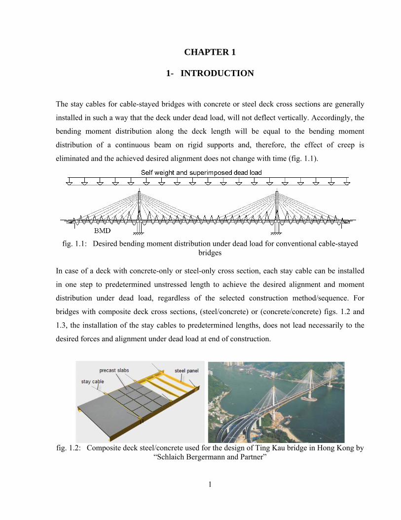
The stay cables for cable-stayed bridges with concrete or steel deck cross sections are generally
installed in such a way that the deck under dead load, will not deflect vertically. Accordingly, the
bending moment distribution along the deck length will be equal to the bending moment
distribution of a continuous beam on rigid supports and, therefore, the effect of creep is
eliminated and the achieved desired alignment does not change with time (fig. 1.1).
fig. 1.1: Desired bending moment distribution under dead load for conventional cable-stayed
bridges In case of a deck with concrete-only or steel-only cross section, each stay cable can be installed
in one step to predetermined unstressed length to achieve the desired alignment and moment
distribution under dead load, regardless of the selected construction method/sequence. For
bridges with composite deck cross sections, (steel/concrete) or (concrete/concrete) figs. 1.2 and
1.3, the installation of the stay cables to predetermined lengths, does not lead necessarily to the
desired forces and alignment under dead load at end of construction.
fig. 1.2: Composite deck steel/concrete used for the design of Ting Kau bridge in Hong Kong by
“Schlaich Bergermann and Partner”

2
fig. 1.3: Composite deck concrete/concrete used for the design of Sungai Prai cable-stayed
bridge in Penang/Malaysia by “Dar Consultants”
The achievement of the desired results will depend on the construction sequence of the deck
elements, the ratio between the moment of inertia of the first part of the composite section to the
moment of inertia of the total composite section and the vertical shift from the center of gravity
of the first part of the composite section to the center of gravity of the total composite section.
The desired results will be affected also by the time dependent forces due to shrinkage and creep.
In this research work a practical construction method will be proposed for cable-stayed bridges
with composite decks, to ensure the achievement of the desired bending moment distribution
similar to that shown in (fig. 1.1) taking into account the section properties of the composite
section elements and the time dependent effects.
Whilst the desired bending moment distribution under dead load at end of construction for
conventional cable-stayed bridges as that shown in (fig. 1.1) is targeted normally by bridge
designers, it is noted that the bending moment distribution under dead load for extradosed
bridges, with the common geometrical configuration shown in (fig. 1.4), is yet to be defined.
fig. 1.4: Common configuration of extradosed bridges

3
In this research work the proposed bending moment distribution under dead load shown in fig.
1.5, will be investigated for extradosed bridges.
fig. 1.5: Proposed bending moment distribution under dead load for extradosed bridges
A composite deck cross section steel/concrete similar to that shown in fig. 1.2 has proven to be a
successful choice for cable-stayed bridges, as far as the ease and speed of construction is
concerned. The composite cross section concrete/concrete shown in fig. 1.3, consists of three
pieces of precast segments. The central precast pieces are match cast spine segments which are
erected first, with their relatively light weights, for the full length of the cable-stayed bridge and
used subsequently as a platform for the erection of the precast side frames on both sides of the
previously erected central segments. The said precast side frame segments are connected to the
central precast spine segments by in-situ concrete stitching and transverse prestressing. The
efficient and successful use of composite deck cross sections for cable-stayed bridges, should
lead to an equal success for extradosed bridges as heavy temporary erection machines may be
avoided. Practical construction methods will be presented in this research, which work for both of
cable-stayed and extradosed bridges with composite decks. They will be a useful tool for bridge
designers and contractors to achieve the desired alignment and forces within the structural
elements for such types of bridges.
The research work will be arranged in the following chapters:
- Cable supported bridges in general (Chapter 2):
The usual types of the stay cables used for cable-stayed and their methods of installation, will
be presented. The structural systems and the behavior of cable-stayed bridges under external
loads will be also briefly discussed.
- Previous research works for cable-stayed bridges related to the recommended stay cable forces
under dead load (Chapter 3):
The methods investigated previously for the determination of the stay cable forces under dead
load for conventional cable-stayed bridges with concrete-only or steel-only deck sections will
be explained.
4
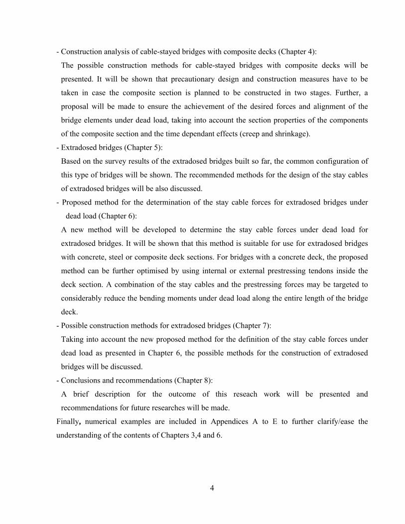
- Construction analysis of cable-stayed bridges with composite decks (Chapter 4):
The possible construction methods for cable-stayed bridges with composite decks will be
presented. It will be shown that precautionary design and construction measures have to be
taken in case the composite section is planned to be constructed in two stages. Further, a
proposal will be made to ensure the achievement of the desired forces and alignment of the
bridge elements under dead load, taking into account the section properties of the components
of the composite section and the time dependant effects (creep and shrinkage).
- Extradosed bridges (Chapter 5):
Based on the survey results of the extradosed bridges built so far, the common configuration of
this type of bridges will be shown. The recommended methods for the design of the stay cables
of extradosed bridges will be also discussed.
- Proposed method for the determination of the stay cable forces for extradosed bridges under
dead load (Chapter 6):
A new method will be developed to determine the stay cable forces under dead load for
extradosed bridges. It will be shown that this method is suitable for use for extradosed bridges
with concrete, steel or composite deck sections. For bridges with a concrete deck, the proposed
method can be further optimised by using internal or external prestressing tendons inside the
deck section. A combination of the stay cables and the prestressing forces may be targeted to
considerably reduce the bending moments under dead load along the entire length of the bridge
deck.
- Possible construction methods for extradosed bridges (Chapter 7):
Taking into account the new proposed method for the definition of the stay cable forces under
dead load as presented in Chapter 6, the possible methods for the construction of extradosed
bridges will be discussed.
- Conclusions and recommendations (Chapter 8):
A brief description for the outcome of this reseach work will be presented and
recommendations for future researches will be made.
Finally, numerical examples are included in Appendices A to E to further clarify/ease the
understanding of the contents of Chapters 3,4 and 6.

5
CHAPTER 2
2- CABLE-STAYED BRIDGES IN GENERAL
As implied by its name, the stay cables differentiate a cable-stayed bridge from other traditional
bridges. The stay cables play a major structural role for cable-stayed bridges. They are designed
normally to carry nearly 100 % of the dead load and serve in addition as elastic supports for the
deck to allow for the safe transfer of the traffic loads to the foundations through the pylons. To
ease the understanding of the next Chapters, the types of stay cables usually used for the
construction of cable- stayed bridges and their methods of installation will be discussed in
Section 2-1. In addition, the common structural systems of the modern cable-stayed bridges will
be briefly presented in Section 2-2. For the readers who are familiar with the design and
construction of cable-stayed bridges, they can go directly to Chapter 3.
2-1 Types of stay cables
In general the steel material used for the stay cables is characterized by its higher carbon content
compared to that of the structural steel. Whilst the carbon content of the structural steel material
is equal to 0.15 to 0.20%, the carbon content of the material used for the stay cables is equal to
0.80% [Gimsing and Georgakis 2011]. Due to its higher carbon content, the tensile strength of
the stay cable material being equal to approximately 1800 MPA is almost equal to more than four
times that of the mild structural steel (=370 MPA). Its tensile strength is also more than twice that
of the high strength structural steel (=790 MPA). The increase in the tensile strength is paid for
by a noticeable decrease of the ductility. The elongation at the breaking point for the stay cable
material is equal to 4%. For the mild structural steel and the high strength structural steel, the
elongation at the breaking point reach values of 24% and 18% respectively [Gimsing and
Georgakis 2011].
The types of cables usually used for cable supported bridges are:
a- Parallel-bar cables.
b- Locked coil strand cables.
c- Parallel-wire cables.
d- Parallel strand cables.

6
2-1-1 Parallel-Bar Cables
Parallel-bar cables are steel threaded bars (fig. 2.1) usually manufactured with diameters 16, 19,
25, 32, 36, 43 and 57mm. The bars with diameters 16mm may be delivered in reels and those
with diameters greater than 16mm are delivered with straight lengths 15 or 20m [Walter et al.
1999]. The continuity of the bars with diameters greater than 16mm may be achieved by using
couplers. The ultimate strength of these types of cables varies between 1030 and 1470 N/mm2 and
they have an elastic modulus equal to 210000 N/mm2. As the ultimate strength of the stressing
bars is generally less than the ultimate strength of the wires used for the fabrication of other types
of stay cables, the cross section of stay cables made out of stressing bars are normally larger. On
the other hand, the use of bigger cross section leads to a reduction in the stresses variations and
enhances the fatigue strength of the stay cables. As shown in fig. 2.1, the stressing bars are
installed normally in metal ducts kept in position by polyethylene spacers and parallel to each
other. The bars can slide in the longitudinal direction which allows the individual stressing of the
steel bars. Upon tensioning all bars, the voids inside the metal ducts around the steel bars are
normally injected with cement grout. The cement grout injection does not only provide the
necessary corrosion protection for the steel bars but contribute in carrying part of the live loads as
well.
fig. 2.1: Parallel bar cables [Walter et al. 1999]
2-1-2 Locked Coil Strand Cables
In the locked coil strand a number of different shapes of wires cross sections are used to form a
strand with a smoother and tighter surface. Typically, the locked coil strand will have a core of a
normal helical strand composed of round wires. Around this core is one to several layers of
wedge shaped wires and the outer layers are of wires with a special S-shape (fig. 2.2). The S-
shape layer forms an envelope which is more or less water tight (hence the name “Locked Coil

7
Cables”) [PFEIFER 2010]. These strands are fabricated by successive spinning of wire layers
generally with opposite direction of helix. As a smaller pitch is used in the multi-wire strands, the
decrease of the stiffness is more than that of the seven wire strands. The nominal elastic modulus
for the multi wire helical strand is about 15-25% less than the value for straight wires [Gimsing
and Georgakis 2011]. The elastic modulus of these types of strands is typically equal to 170000
N/mm2. When the first loading is applied to a helical strand, the elongation will be due not only
to the elastic strain in the wires, but also to an irreversible elongation caused by the compaction
of the strand. To remove this non-elastic elongation, a pre-stressing is applied to make the strand
behave in a nearly ideal elastic manner in the final structure. The locked coil strands are
fabricated generally with diameters ranging from 30mm to 150mm. The largest diameters of
locked coil strands are used for cable-stayed bridges in which a stay cable may be made of one
single strand. The smaller diameters (60 to 80mm) are used in cases where the final cable is
composed of several strands. As opposed to other types of stay cables, stay cables with locked
coil strands are installed without external ducts or grouting and for this reason, they have to be
fabricated with care as far as the corrosion protection of all of their wires, is concerned.
fig. 2.2: Locked coil strand
2-1-3 Parallel Wire Cables
They consist of bundles of 7mm diameter wires (figs. 2.3 to 2.5). The number of wires in each
bundle is varying between 50 and 350. The ultimate strength of the wires of these types of cables
is equal to 1670 N/mm2. This means that the ultimate load capacity of one wire can reach a value
of 6.5 tons and the ultimate load capacity of a bundle with 300 wires will be equal to 1950 tons.
The elastic modulus of these types of cables is about 205000 N/mm2 which is a little less than
that of the parallel bar cables. The results of the tests carried out on stay cables system with
parallel wires, have shown that they can withstand stress variations of 350-400 N/mm2 over two
million cycles with a maximum stress of 750 N/mm2 which is nearly equal to 45% of the ultimate
tensile stress of the wires material [Walter et al. 1999]. Fig. 2.6 shows testing the fabricated stay

8
cable with its full length prior to its delivery to the erection site. The jacking load in the test is
normally equal to 1.5 times the maximum expected load during the service live of the stay cable.
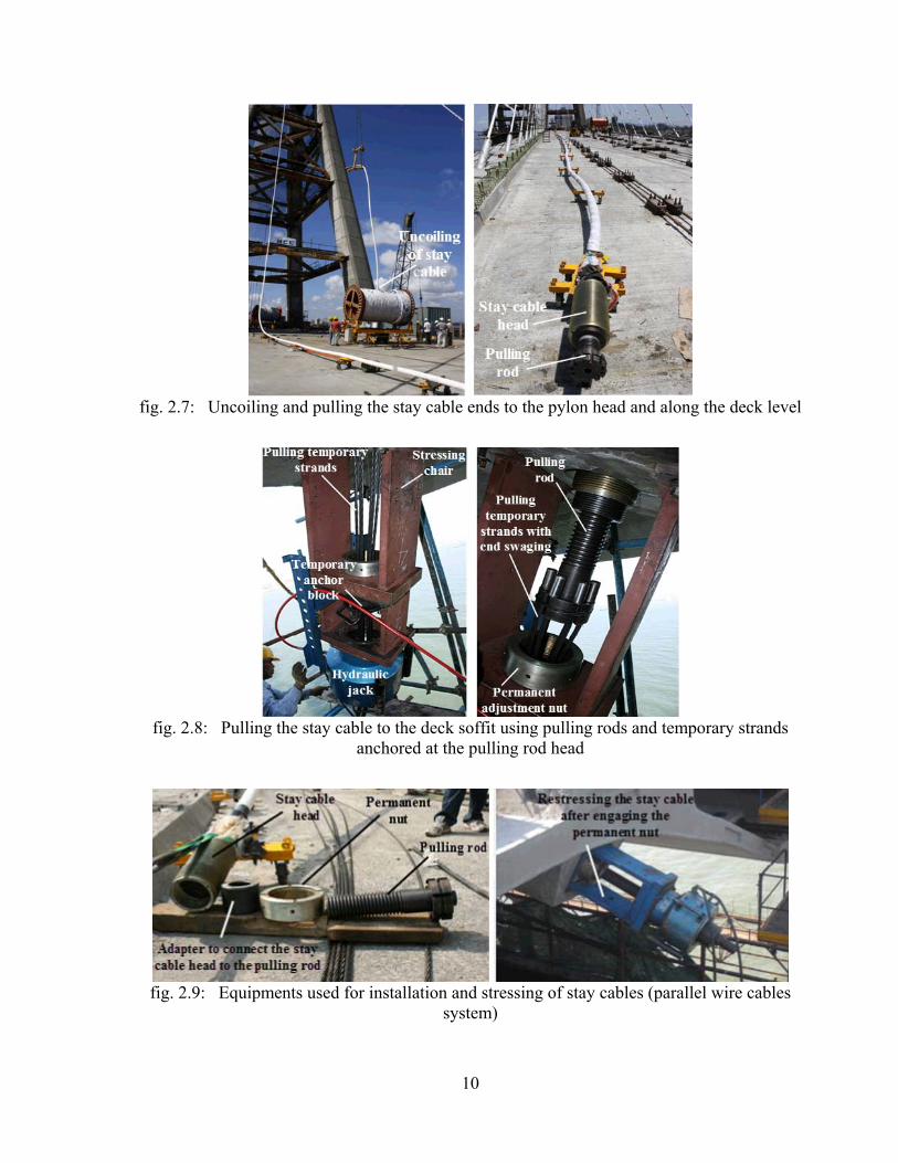
Fig. 2.7 shows that the stay cables with parallel wires are manufactured with its full length in the
factory and delivered to the erection site with special coils. As it is the case for BBR-HiAm stay
cable system, all of the individual parallel wires are galvanized by immersing the wires in a bath
of melted zinc. The wires are covered by internal black HDPE-layer and external white HDPE-
layer. The external HDPE-layer can be made of any desired color which has normally to be anti-
violet. Figs. 2.4 and 2.5 show the method of anchoring the stay cable wires inside the stay cable
head. The ends of the wires are swaged to allow the wires to be anchored to the outer face of a
perforated steel plate. Subsequently the stay cable head under the perforated steel plate is grouted
by a mix of epoxy resin, zinc powder and steel balls. It is also to be noted that the stay cable head
is threaded from inside and outside. The inside threading allows pulling the stay cable by a
pulling rod during installation and the outside threading helps to anchor the stay cable head to a
bearing plate using a special nut (figs. 2.7 to 2.9). The fabrication length of the stay cable has to
be determined with care allowing appropriate tolerances. In case the stay cable is found at the
erection site too long, additional steel shims fabricated in two half, will have to be inserted
between the permanent nuts and the bearing plates. These shims may have to be placed at both
ends of the stay cables. In case the stay cable is found too short, it may have to be re-fabricated to
avoid the overstressing of the stay cable or breaking and recasting the concrete at the anchorage
locations. Breaking and recasting the concrete to shorten the distance between the stay cable ends
is very tedious and time consuming due to the common reinforcement congestion at the
anchorage zones.
fig. 2.3: Stay cables with parallel wires cables/ BBR-HiAm system [www.bbrnetwork.com]
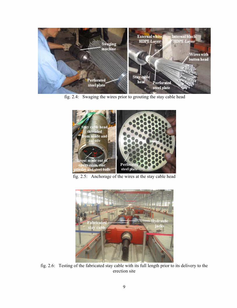
9
fig. 2.4: Swaging the wires prior to grouting the stay cable head
fig. 2.5: Anchorage of the wires at the stay cable head
fig. 2.6: Testing of the fabricated stay cable with its full length prior to its delivery to the
erection site
10
fig. 2.7: Uncoiling and pulling the stay cable ends to the pylon head and along the deck level
fig. 2.8: Pulling the stay cable to the deck soffit using pulling rods and temporary strands
anchored at the pulling rod head
fig. 2.9: Equipments used for installation and stressing of stay cables (parallel wire cables
system)

11
2-1-4 Parallel Strand Cables
They consist of bundles of strands. The strand is normally made from seven wires with 5mm
diameter each. These strands are the simplest to be found within the cable supported bridges. At
present they are widely used as tendons of pre-stressed concrete structures. The seven-wire strand
consists of a single straight 5mm diameter wire core surrounded by a single layer of six wires
giving the strand a nominal diameter of 15mm and a nominal cross sectional area equal to
150mm2 (figs. 2.10 and 2.11). All of the six wires, surrounding the said core wire, have the same
pitch and direction of helix. As the pitch is relatively large, the inclination of the wire axis in
respect to the strand axis is small. This means that the stiffness of the seven-wire strand is nearly
equal to that of the straight wires. Typically, the nominal elastic modulus for the seven–wire
strand will be 5-6% less than that of the wires. The typical elastic modulus of these types of
cables is equal to 195000 N/mm2 [Gimsing and Georgakis 2011]. Figs. 2.12 and 2.13 show the
components of the stay cable head and the special wedges used for the anchorage of the
individual strands at the outer face of the anchorage block [Freyssinet 1999]. The international
codes and specifications recommend to test the stay cable system of this type for fatigue strength.
The stay cables have to prove a fatigue strength of about 200 N/mm2 at a maximum stress of 750
N/mm2 with two million cycles. The bites/pinches applied by the wedges on the strands are
normally the reasons for the low fatigue strength of the stay cable with parallel strands when
compared with the stay cables made of parallel wires. As shown within figs. 2-10 and 2.11, the
individual strands of Freyssinet stay cable system are galvanized and coated with a thin black
HDPE-layer after filling the interstices of its 7-wires with special petroleum wax. The strand
bundle is placed inside a colored external HDPE-layer. Fig. 2-10 shows also that the external
HDPE-layer is provided with helical ribs which enhance the stay cables behavior under the effect
of wind and/or rain.
fig. 2.10: Components of parallel strand cables [www.freyssinetusa.com]

12
fig. 2.11: Cross sections through the strand bundle and the mono-strand used for Freyssinet stay
cable system [Freyssinet 1999]
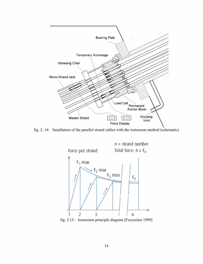
The parallel strands stay cables are installed normally strand by strand. Due to the flexibility of
deck and tower, the force of the individual strands of a stay cable varies during the stressing
operation. To ensure uniformity of force in all strands of a stay at the end of the stressing
operation, a patented method has been developed by Freyssinet, called Isotension [Freyssinet
1999]. The principle of the Isotension may be described as follows (figs. 2.14 and 2.15):
- The first strand (“the master strand”) is fixed to one of the stay cable two anchorages and its
other end is threaded into the other anchorage and then cut and stressed to a calculated force,
using the theoretical numerical model of the bridge structure. Due to the flexibility of the
structure, the calculated force of the master strand, has to be higher than the desired strand
force when all strands of the stay cables are stressed.
- The wedge of the master strand is not yet engaged to the stay cable anchor block. The master
strand is instead wedged to a special single anchoring device provided with a load cell which
gives the reading of the current master strand force.
- The second strand is then installed in a similar manner, cut and stressed. The stressing is done,
as for the master strand, with a mono-strand jack equipped with a load cell identical to the one
indicating the force of the master strand. As the second strand is stressed, the force in the first
strand decreases and the stressing operation is stopped when the readings of the two load cells
are identical. The second strand is then anchored/wedged to the permanent anchor block. The
two strands are equally stressed.

13
- The third strand is then installed and stressed until its force reaches the force of the master
strand (which decreases jointly with the force of the second strand). The three strands are
identically stressed.
- The same operation is repeated until the last strand of the stay cable. The last reading of the stay
is then to be compared with the expected theoretical force. The stay cable force may then be
adjusted by the multi-strand jack if necessary.
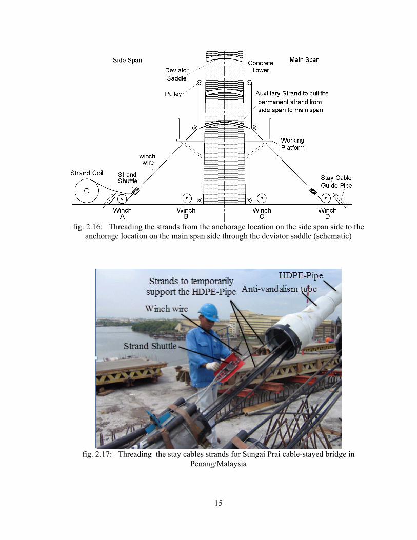
Figs. 2-16 to 2.18 show the installation for the stay cables of Sungai Prai Bridge in
Penang/Malaysia. Fig. 2.16 shows a schematic for the method used for threading the strands
using 4-winches noting that the stay cables for this bridge are anchored to the tower head by
using the saddle system.
fig. 2.12: Anchorage components of parallel strand stay cable [www.freyssinetusa.com]
fig. 2.13: Anchorage block used for Freyssinet stay cable system
14
fig. 2: 14: Installation of the parallel strand cables with the isotension method (schematic)
fig. 2.15: Isotension principle diagram [Freyssinet 1999]
15
fig. 2.16: Threading the strands from the anchorage location on the side span side to the
anchorage location on the main span side through the deviator saddle (schematic)
fig. 2.17: Threading the stay cables strands for Sungai Prai cable-stayed bridge in
Penang/Malaysia

16
fig. 2.18: Installation of the parallel strand cable by the “strand by strand” method
2-1-5 Anchorages of Stay Cables at Deck and Tower head Levels
The stay cables are manufactured normally with one active end and one passive end during the
installation/stressing operation. The stay cable may be stressed at the deck level or at the pylon
head level. Figs. 2.19 and 2.20 show two types of passive and active stay cable anchorages at
deck level.
fig. 2.19: Passive anchorage at deck level fig. 2.20: Active anchorage at deck level [Leonhardt and Zellner 1980]
Figs. 2.21 to 2.28 show different possibilities for the stay cable anchorages at the tower head. In
case the dimensions of the tower head allow the arrangement of a central chamber, a solution

17
similar to that shown within fig. 2.21 may be followed. The central chamber should normally be
sufficiently large to handle the equipment necessary for pulling and stressing the stay cables. In
case the dimensions of the tower head are too small to accommodate the anchorages of the stay
cables and/or the provision of a central chamber, one of the anchorage systems similar to that
shown within figs. 2.22 and 2.24 may be adopted. Figs. 2-22 and 2.23 show the tower head for
Ting Kau bridge in Hong King. The width and the length of the slender concrete tower head cross
section, being equal to 5 and 10m respectively, were not adequate to anchor 8-stay cables in one
level. Accordingly additional two external steel boxes had to be connected to the concrete tower
head section to allow the anchorage of the stay cables in the manner shown within fig. 2.22. The
overcrossing of stay cables may be chosen in case the arrangements of the stay cables anchorages
are made in such a way that the torsion/twist of the tower head are to be avoided as it is the case
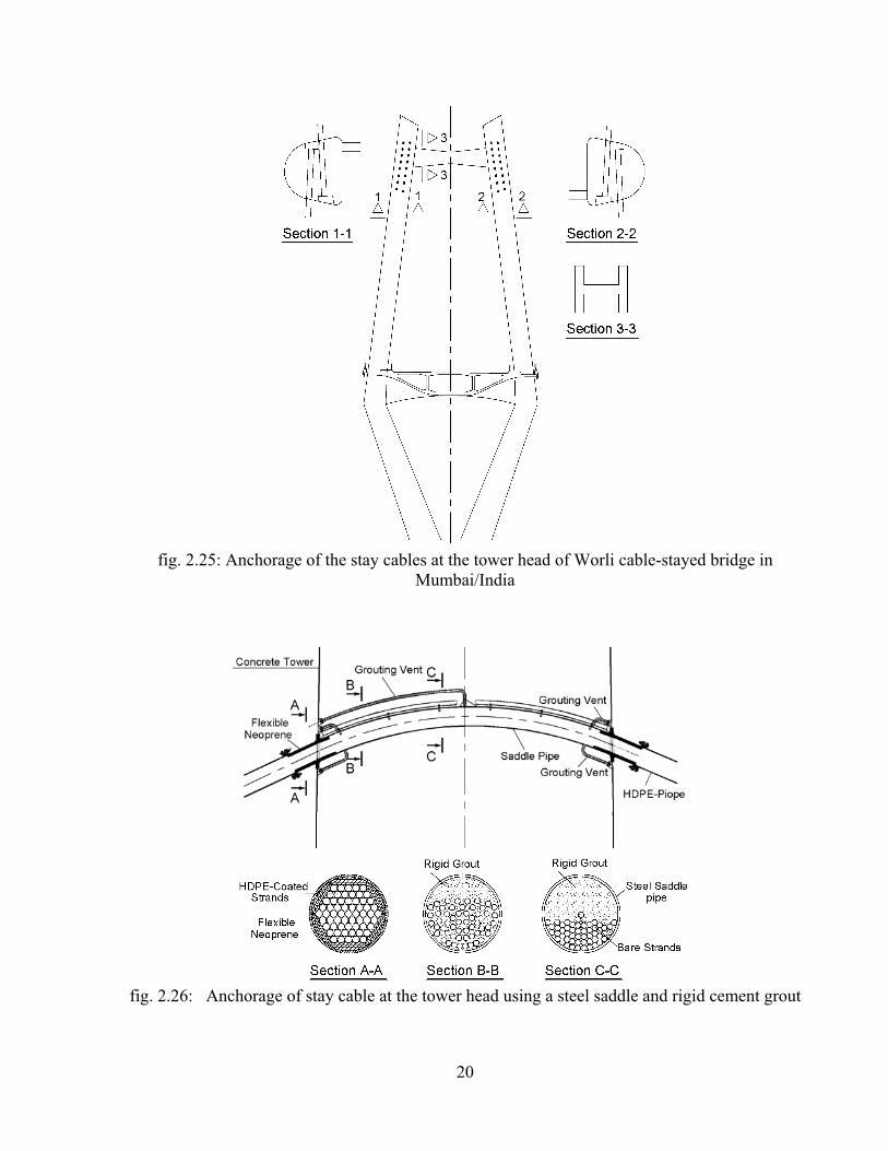
for the configuration shown within fig. 2.24. For the towers of Worli cable-stayed bridge in
Mumbai/India (fig. 2.25) a cross beam connecting the top of the tower heads has been
constructed to carry/reduce the twist of the tower heads resulting from the arrangement of the
stay cable anchorages shown within sections 1-1 and 2-2. The use of deviation saddles at the
tower head as that shown within figs. 2.26 and 2.27 helps to save the anchorages at the tower
head, simplify the design and construction of the tower head and helps also to achieve a slender
tower head as the saddle normally does not occupy big space of the tower head section. For
Sungai Prai Bridge in Malaysia, each stay cable consists of strands of the type shown within fig.
2.11. Each strand is continuous from the deck anchorage in the side span to the deck anchorage in
the main span. As shown within sections A-A, B-B and C-C of fig. 2.26, the black HDPE-layer
covering every single strand outside the steel saddle are removed inside the saddle. To avoid the
slippage of the strands inside the saddle resulting from the possible unsymmetrical live loads on
both sides of the tower head, the saddle tube was injected with cement grout upon the installation
of all strands. Despite of the said injection of the saddle with cement grout, the removal of the
black HDPE-layer around the individual strands inside the saddle, may be problematic with
respect to the corrosion protection, fatigue resistance and the possibility to replace the stay cables
when necessary. To avoid these disadvantages, Freyssinet developed a high performance
deviation saddle, called the multi tube saddle and used what is called Cohestrand [Lecinq et al.
2005]. The Cohestrand is similar to the strand shown within figure 2.11 except for the petroleum
wax which is replaced by a special resin which is a compound of polybutadiene (PolyBd) resin

18
wrapping all the wires including the core wire and adhesion element (Orevac) on polyethelene.
The key aspect of the Cohestrand manufacturing is the co-extrusion of the PolyBd, the Orevac
and the polyethylene onto the strand to obtain a sufficient bond. The minimum shear resistance of
the compound shall be 4.0 N/mm2 at 20C0 between the outer sheath and the 7-wire strand. The
triple anticorrosion barrier of the Cohestrand can be maintained also inside the deviation saddle
without any discontinuity. This is the key to avoid any weak point in the corrosion protection of
the cables. The saddle is made of a bundle of individual deviation tubes placed inside a large steel
saddle tube. The space between the individual tubes is filled in factory with a special high
strength cement grout (compression strength at 28-days > 130 N/mm2). The saddle is delivered to
the site fully assembled and grouted. Upon the installation of the saddle in the tower head, the
strands are threaded one by one through the individual tubes. The saddle provides an individual
deviation of each strand by a small tube and the fix point of the cable is obtained from friction of
each strand on its individual deviation tube. Using Cohestrand, the friction can be transferred
through the sheath, hence the HDPE sheath of the strand is continuous through the saddle and the
corrosion protection of the free length is not interrupted in the saddle. A special surface treatment
of the tubes ensures that the friction coefficient between the strand and the saddle is greater than
0.5 which is normally enough to block unsymmetrical forces in most bridges. As the radial forces
are not transmitted between the strands, the fatigue performance of the multi-tube saddle is
improved. It has been tested successfully for two million cycles of 200 N/mm2 axial fatigue
loading. The saddle enables also the replacement of each strand. The deviation saddle with the
Cohestrand was implemented for the first time for Sungai Muar cable-stayed bridge in
Johor/Malaysia (fig. 2.28 and 2.29). The bridge was designed by “Jean-Muller International”. Its
total length is equal to 632m with main span of 132m. The multi tube saddles were manufactured
and grouted in France, then delivered to Malaysia. The stay cable sizes range from 37 to 73
strands. The stays were installed strand by strand and stressed simultaneously from both of its
ends with the Iso-tension system.
VSL developed also a saddle system allowing “strand by strand” installation and replacement.
The saddle in this system is composed of a steel box filled with a high strength ductal type
cement grout. Each strand is installed without the black HDPE-sheating in individual slightly
ovalised V-shape hole and special grout is used when the strand installation is completed [VSL
2008]. This saddle system was intensively tested at the TU-Berlin [Schlaich et al. 2012].

19
fig. 2.21: Stay cable anchorages inside the tower head
fig. 2:22: Anchorage of stay cables using external steel box
fig. 2.23: Tower head of Ting Kau bridge fig. 2.24: Overcrossing of stay cables [Leonhardt and Zellner 1980]
20
fig. 2.25: Anchorage of the stay cables at the tower head of Worli cable-stayed bridge in
Mumbai/India
fig. 2.26: Anchorage of stay cable at the tower head using a steel saddle and rigid cement grout

21
fig. 2.27: Placement of steel saddles within the tower head before concreting
fig. 2.28: The prefabricated saddles used for Sungai Muar cable-stayed bridge in Johor/Malaysia
[Lecinq et al. 2005]
fig. 2.29: Sungai Muar cable-stayed bridge in Johor/Malaysia
[Lecinq et al. 2005]

22
2-2 Possible structural systems for conventional cable-stayed bridges (supporting system
between the tower and the deck & between the deck and the end support)
The contribution of each bearing element of a conventional cable-stayed bridge (towers, stay
cables and deck) in carrying the self weights and/or the external loads depends to a great extent
on the chosen supporting system. Cable-stayed bridges may have one of the configurations
shown in fig. 2.30. The modern form of cable-stayed bridges started first with the use of few
numbers of stay cables acting as elastic supports for a relatively stiff deck fig. 2.30 (a) [Leonhardt
and Zellner 1980]. In this system only slender towers over the deck level are required as they will
carry the vertical component forces of the said few numbers of stay cables, and may also carry
small bending moments. Similar to the extradosed bridges, which will be dealt with in Chapters 5
and 6, the bridge configuration shown in fig. 2.30 (a), does not have backstays connecting the
tower tip to the rigid end support. The stability of this bridge configuration is achieved mainly by
its stiff deck.
As opposed to the structural system of the bridge shown in fig. 2.30 (a), the bridge in fig. 2.30 (b)
has a slender deck and is provided with back stays connecting the tip of the tower to the rigid end
supports, serving to stabilize the towers in the longitudinal direction. The rocker bearings are
connected at their top ends to the deck by hinges. They have also hinges at their bottom ends.
The main function of these rocker bearing is to carry the vertical component forces of the
backstays while allowing the horizontal movement of the deck. The horizontal component forces
of the back stays, in this particular structural system, will be carried by the deck and they will
balance the horizontal component of the stay forces of the main span side. As the deck moves
longitudinally under the effect of temperature changes, shrinkage, creep or live loads, the rocker
bearings will move with the deck at their top ends and will therefore rotate around their bottom
hinges. According to the extent of these movements, the height of the rocker bearings should be
chosen so that no restraining actions between the deck and the rocker bearing will be introduced.
The bridge shown in fig. 2.30 (c) is characterized by its stiff tower. This type of tower will not be
in need of back stays as in the case of the bridge shown in fig. 2.30 (b). The bridge configuration
shown in fig. 2.30 (d) is not common in that it has an expansion joint at the center of its main
span and not at the bridge ends. The backstays are anchored outside the bridge deck and the deck
is fixed to the end supports. The supporting system configuration shown in fig. 2.30 (d) was
adopted for Barrios de Luna bridge in Spain [Walter et al. 1999]. The structural system of the
23
bridge shown in fig. 2.30 (e) is similar to that shown in fig. 2.30 (d), but the deck in this
configuration has two expansion joints arranged near the towers. For the bridge configurations
shown in figs. 2.30 (b) and (c), the deck may be rigidly connected to one of the towers or left
swimming in the longitudinal direction. The deck of the bridges in fig. 2.30 (d) and (e) may be
connected to the towers in the longitudinal direction only in case of relatively short side spans
and/or flexible tall towers above the ground to avoid high restraining forces between the towers
and the deck. Under dead load, the decks of the bridges shown in figs. 2.30 (a) to (d) are under
compression normal forces, and the deck of the bridge shown in fig. 2.30 (e) is under tension
normal force. In this connection, it should be noted that the choice of a steel deck is best suitable
for the configuration of fig. 2.30 (e). This configuration was selected by F. de Miranda for the
design of the bridge over the Arno [Walter et al. 1999].
If there is no need for large free side span and the site conditions permit, one or more additional
piers in the side span as shown in fig. 2.30 (f) may be introduced. This will help to reduce the
uplift force which has to be carried by the rocker bearings at the end of the side span.
It can also be understood that each half of the cable-stayed bridges shown in figs. 2.30 (b) to (d)
and (f), from the middle of the main span to the end support, is statically stable. This is not valid
for the bridge configuration shown in fig. 2.30 (e). Each half of this bridge configuration cannot
stand alone similar to the case of the common suspension bridge configuration.
To resist the transverse wind loads acting on the deck and cables, the deck is normally supported
in the transverse direction in all configurations shown in (fig. 2.30) at the towers and at the end
supports at both bridge ends.

24
fig. 2.30: Possible structural systems for conventional cable-stayed bridges

25
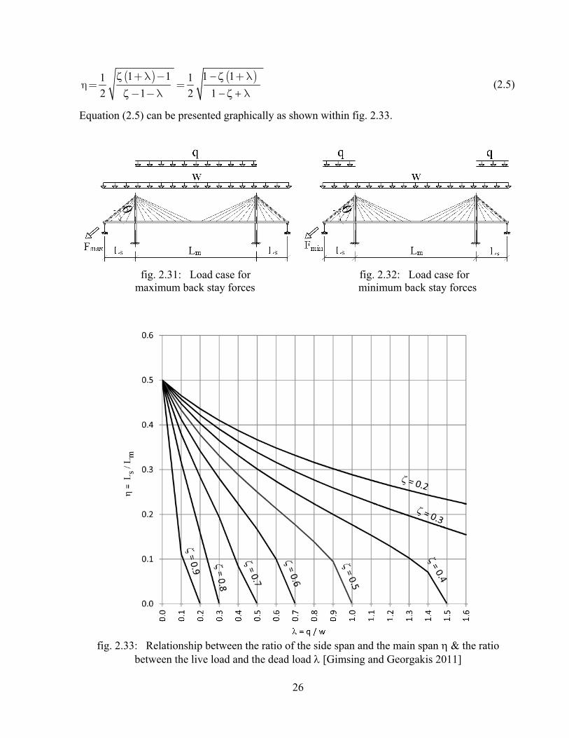
Ratio between the side span and the main span length:
The backstays of the modern cable-stayed bridges play a dominant role to ensure the overall
stability of the structural system. They help to stabilize the tip of the tower as they hold the tower
back towards the side span when the main span carries live load. The live load q on the main span
increase the backstay forces fig. 2.31. The backstay forces are reduced to their minimum level
when the live load q occupy only the side span fig. 2.32. The backstays get normally the largest
stress variations/amplitudes compared to all other cables. They have to be dimensioned in such a
way that the said stress variations are kept safely below their fatigue strength.
From figures 2.31 and 2.32 and by ignoring the bending stiffness of deck and assuming that all
stay cables intersect at the top of the tower head, the following equations may be written
[Gimsing and Georgakis 2011]:
( )
2m
2s
max s
LL2
F L sin (q+w) w2 2
æ ö÷ç ÷ç ÷çè øq = -
(2.1)
( )
2m
2s
min s
LL2
F L sin w (q+w)2 2
æ ö÷ç ÷ç ÷çè øq = -
(2.2)
By dividing both sides of equation 2.2 over the corresponding sides of equation 2.1, the following
equation can be obtained:
( )( )
2 2m smin
2 2max m s
w L 4 w q LF
F w q L 4 w L
- +=
+ -
(2.3)
smin
max m
LF qAssuming that , ,
F w Lh =
The ratio between the minimum and maximum backstay forces can be determined from the
following equation:
( )( )
2
2
1 4 1
1 4
- + l hh =
+ l - h
(2.4)
By rearrangement, the following equation can also be obtained:
26
( ) ( )1 1 11 1
2 1 2
+ l - + lh = =
- - l l
(2.5)
Equation (2.5) can be presented graphically as shown within fig. 2.33.
fig. 2.31: Load case for fig. 2.32: Load case for maximum back stay forces minimum back stay forces
fig. 2.33: Relationship between the ratio of the side span and the main span & the ratio
between the live load and the dead load [Gimsing and Georgakis 2011]

27
From the above equations and diagram the following can be observed:
- For a specific ratio between the side span and the main span length , the ratio between the
minimum and maximum backstay forces decreases with the increase of the ratio between the
live load and the dead load. The above diagram shows that for = 0.3, decreases from
approximately 0.8 to 0.2, if increases from 0.1 to 0.9.
- For a specific ratio of , decreases with the increase of . In case is equal to 0.3 for example
and it is not desired to reduce below 0.3, can not be made greater than 0.4.
- As it is known from the previous experience that for cable-stayed bridges with concrete and
steel deck is equal to approximately 0.2 and 0.4 respectively, therefore, if it is desired to ensure
that will not be less than 0.25, it will be necessary to ensure that will not be more than 0.42
for a bridge with a concrete deck and not more than 0.37 for a bridge with a steel deck.
It has to be noted further that it is generally desired by the bridge designer to ensure that the
backstay forces/stresses will not be reduced below a specific value as the stay cable stress
reduction will lead to higher sag and consequently undesired reduction of the stay cable elastic
modulus as will be explained later in this Section. It should also be kept in mind that the above
equations 2.1 to 2.5 and fig. 2.33 have been derived with the assumptions that the dead and live
loads are uniformly distributed along the main span and the side span lengths. It was assumed
also that the stay cables have the fan shape and the deck of the side span is not supported at any
intermediate supports. In case one or more of the assumptions made are not applicable, the above
equations and diagram will not be valid and it may be necessary to derive similar equations for
the bridge under consideration.
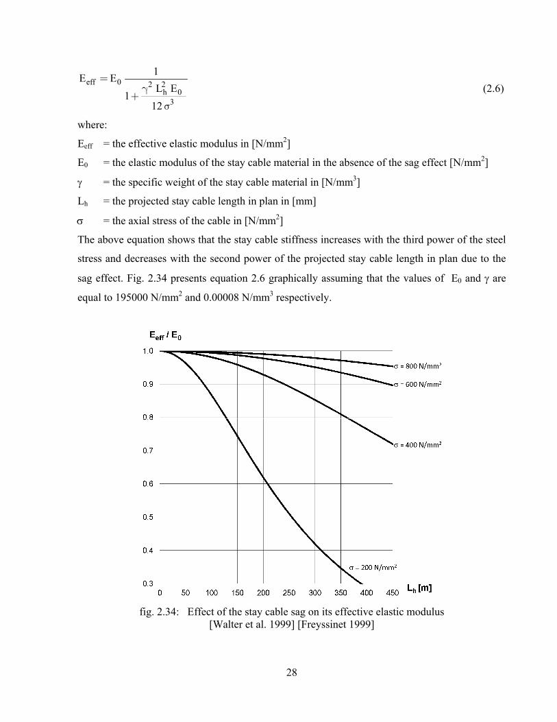
Stiffness of Stay Cables:
The stay cables under dead load take a catenary form. Due to the sag of the stay cables under
dead load, the effective elastic modulus Eeff will be less than the elastic modulus for the stay
cables steel material E0. If the cables are simulated as straight elements in a computer model, say
with truss elements, a modulus of elasticity Eeff < E0, should be used especially in case the cable
is too long (refer to fig. 2.34). Eeff is influenced by the self weight of cable in addition to its length
and force. The effective elastic modulus Eeff can be calculated from the following equation
known as Ernst formula [Walter et al. 1999]:
28
eff 0 2 2h 0
3
1E E
L1
12
=g
+s
(2.6)
where:
Eeff = the effective elastic modulus in [N/mm2]
E0 = the elastic modulus of the stay cable material in the absence of the sag effect [N/mm2]
= the specific weight of the stay cable material in [N/mm3]
Lh = the projected stay cable length in plan in [mm]
= the axial stress of the cable in [N/mm2]
The above equation shows that the stay cable stiffness increases with the third power of the steel
stress and decreases with the second power of the projected stay cable length in plan due to the
sag effect. Fig. 2.34 presents equation 2.6 graphically assuming that the values of E0 and are
equal to 195000 N/mm2 and 0.00008 N/mm3 respectively.
fig. 2.34: Effect of the stay cable sag on its effective elastic modulus [Walter et al. 1999] [Freyssinet 1999]
29
CHAPTER 3
3- PREVIOUS RESEARCH WORKS FOR CABLES-STAYED BRIDGES RELATED TO THE RECOMMENDED STAY CABLE FORCES UNDER
DEAD LOAD
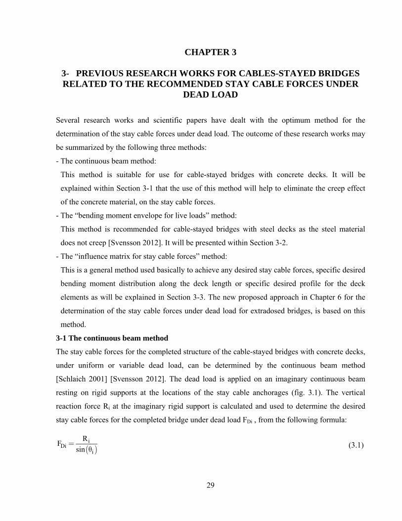
Several research works and scientific papers have dealt with the optimum method for the
determination of the stay cable forces under dead load. The outcome of these research works may
be summarized by the following three methods:
- The continuous beam method:
This method is suitable for use for cable-stayed bridges with concrete decks. It will be
explained within Section 3-1 that the use of this method will help to eliminate the creep effect
of the concrete material, on the stay cable forces.
- The “bending moment envelope for live loads” method:
This method is recommended for cable-stayed bridges with steel decks as the steel material
does not creep [Svensson 2012]. It will be presented within Section 3-2.
- The “influence matrix for stay cable forces” method:
This is a general method used basically to achieve any desired stay cable forces, specific desired
bending moment distribution along the deck length or specific desired profile for the deck
elements as will be explained in Section 3-3. The new proposed approach in Chapter 6 for the
determination of the stay cable forces under dead load for extradosed bridges, is based on this
method.
3-1 The continuous beam method
The stay cable forces for the completed structure of the cable-stayed bridges with concrete decks,
under uniform or variable dead load, can be determined by the continuous beam method
[Schlaich 2001] [Svensson 2012]. The dead load is applied on an imaginary continuous beam
resting on rigid supports at the locations of the stay cable anchorages (fig. 3.1). The vertical
reaction force Ri at the imaginary rigid support is calculated and used to determine the desired
stay cable forces for the completed bridge under dead load FDi , from the following formula:
( )i
Dii
RF
sin =
q (3.1)
30
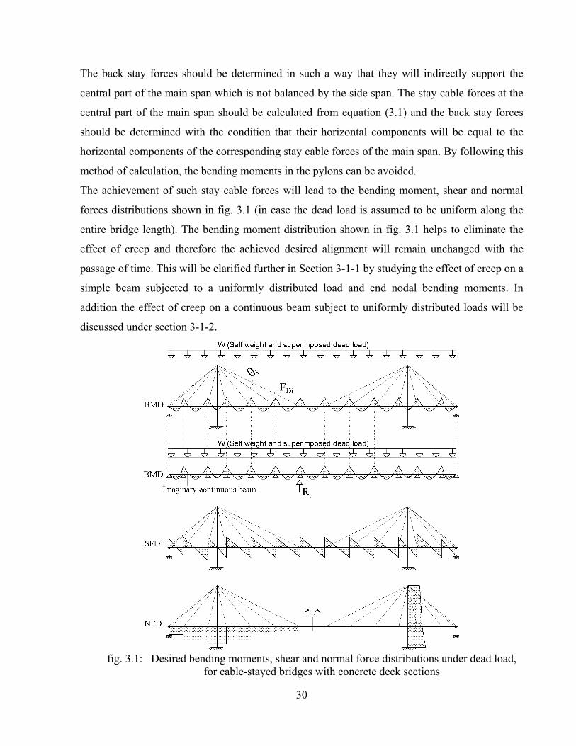
The back stay forces should be determined in such a way that they will indirectly support the
central part of the main span which is not balanced by the side span. The stay cable forces at the
central part of the main span should be calculated from equation (3.1) and the back stay forces
should be determined with the condition that their horizontal components will be equal to the
horizontal components of the corresponding stay cable forces of the main span. By following this
method of calculation, the bending moments in the pylons can be avoided.
The achievement of such stay cable forces will lead to the bending moment, shear and normal
forces distributions shown in fig. 3.1 (in case the dead load is assumed to be uniform along the
entire bridge length). The bending moment distribution shown in fig. 3.1 helps to eliminate the
effect of creep and therefore the achieved desired alignment will remain unchanged with the
passage of time. This will be clarified further in Section 3-1-1 by studying the effect of creep on a
simple beam subjected to a uniformly distributed load and end nodal bending moments. In
addition the effect of creep on a continuous beam subject to uniformly distributed loads will be
discussed under section 3-1-2.
fig. 3.1: Desired bending moments, shear and normal force distributions under dead load,
for cable-stayed bridges with concrete deck sections
31
As an alternative to the use of equation (3.1) the desired stay cable forces FDi may be also
obtained by modeling the whole structure including the stay cables. By the assignment of
imaginary high values of the cross sectional areas for the beam elements of the pylon, deck and
the truss elements of the stay cables (i.e. by making them very stiff), the stay cable forces
resulting from the application of the dead load W, will be equal to the desired stay cable forces
FDi directly.
3-1-1 Effect of creep on a simple concrete beam
Creep of the concrete material occurs normally due to a constant load/stress introduced at time t1
and sustained for a time period (t2-t1) [fig. 3.2 (a) and (b)]. As shown in fig. 3.2(b), the
instantaneous elastic shortening el takes place due to the applied stress at time t1. If the
applied stress is sustained for a period of time (t2-t1), the concrete material will suffer additional
creep strain cr .
The effect of creep on a simple concrete beam subject to “permanent” uniform distributed load W
and “permanent” nodal end bending moments M, is shown in fig. 3.2 (c) to (l). The uniform load
W shown in fig. 3.2 (c) leads to the bending moment distribution and the elastic deflection line
shown in figs. 3.2 (d) and (e) respectively. If the uniform load W remains acting on the beam, the
deflection line of the beam will move downwards with the passage of time due to creep of the
concrete material as shown with the dotted line in fig. 3.2 (e). Similarly, the beam under the
permanent nodal loads M will deflect upwards elastically first and the deflection line will move
upwards with the passage of time due to creep of the concrete material [refer to figs. 3.2 (f) to
(h)]. The absolute values for the angle of rotations |w| and |m| of the elastic deflection lines at
the supports due to the uniform and the nodal loads W and M, may be calculated from the
following equations:
3
wc
W L
24 E Iq =
(3.2)
mc
M L
2 E Iq =
(3.3)
where Ec is the elastic modulus of the concrete material and I is the moment of inertia of the
beam cross section.
32
Now, if the permanent uniform and nodal loads W and M are applied on the concrete beam
simultaneously as shown in fig. 3.2 (i), the resulting elastic deflection line will be the sum of the
elastic lines shown in figs. 3.2 (e) and (h) and its final shape will be dependent on the magnitudes
of W and M. It can easily be concluded that in case the absolute value of |M| is less than the
absolute value of |WL2/12| (i.e. in case |w| > |m| ), the beam will tend to creep downwards as
shown in fig. 3.2(j) and will creep upwards in case |M| is greater than |WL2/12| (i.e. in case |w| <
|m| ) as shown in fig. 3.2(l). In case |M| = |WL2/12| (i.e. case |w| = |m| ), the resultant elastic
rotation at the supports will be equal to zero and will not be affected by creep. However, the
beam elements between the end supports will continue to creep and the sum of the elastic and
creep deflection at the middle of the beam will be equal to:
( ) 2 4el cr
c
1 1 5Z M L W L
E I 8 384+æ ö+f ÷çD = - ÷ç ÷çè ø
(3.4)
where isthe creep coefficient.
As the simple beam is a determinate structure, the rotation of the beam will not be restrained and
the bending moment distribution due to the uniform load W in fig. 3.2 (d) or due to the nodal
bending moment M in fig 3.2 (g) will not be affected by creep.

33
fig. 3.2: Creep effect on a simple concrete beam
34
3-1-2 Effect of creep on a continuous concrete beam
The effect of creep on a simple beam under the uniform dead load W and the end nodal bending
moments M as explained under Section 3-1-1 will ease the understanding of the creep effect on a
continuous beam under uniform dead loads which will be explained in this Section. Further, the
creep effect on a continuous beam will help to understand the creep effect on a cable-stayed
bridge.
The method of calculations of the bending moments and deflections of a continuous beam due to
the creep effect, will be explained in this Section.
Fig. 3.3(a) shows a continuous beam with “n+1” nos. of spans under permanent uniform dead
loads equal to W1, W2, …., Wn+1 . The moment of inertias of the beam cross sections are assumed
to be equal to I1, I2, …., In+1 . For the calculations of the bending moments M1 to Mn at the
internal supports “i to n” shown in fig. 3.3(b), the beam segments nos. i and “i+1” are first
separated as shown in fig. 3.3 (c) where the continuity of the beam segment is replaced by
couples of hog bending moments at their ends. The achievement of the compatibility condition
between the beam segment no. i and the beam segment no. i+1, under the dead loads Wi and
Wi+1, requires that the angle of rotation of the elastic deflection line on both sides of the internal
support no. i, must be equal (i.e. iL = iR). Accordingly, the following equations may be written:
3i i i 1 i i i
iLc i c i c i
W L M L M L
24 E I 6 E I 3 E I
-- - -
q = + +
3i 1 i 1 i i 1 i 1 i 1
iRc i 1 c i 1 c i 1
W L M L M L
24 E I 3 E I 6 E I
+ + + + +
+ + +
- -q =
33i 1 i 1 i i 1 i 1 i 1i i i 1 i i i
c i c i c i c i 1 c i 1 c i 1
W L M L M LW L M L M L
24 E I 6 E I 3 E I 24 E I 3 E I 6 E I
+ + + + +-
+ + +
-= (3.5)
Note: The above equations have been written based on the assumption that the hog bending
moments have negative values and that the angles of rotation of the beam axis are positive in the
clockwise direction.
The rearrangement of equation (3.5) leads to the following equation:
33i i 1 i i 1 i 1 i 1i 1 i i i i i
i i i 1 i 1 i i 1
M L M L W LM L M L W L
6I 3I 3I 6I I 24I
+ + + +-
+ + +
æ ö÷ç ÷- + + = +ç ÷ç ÷çè ø (3.6)
Equation 3.6 may be translated into a matrix form for the entire continuous beam as follows:

35
1 2 2
1 2 2
3 32 2
2 2 3 3
i 1 i 1i i
i i i 1 i 1
n 1 n 1 n n
n 1 n 1 n n
n 1n n
n n n 1
L L L0 0 0 0 0
3I 3I 6I
L LL L0 0 0 0
6I 3I 3I 6I
.... .... .... .... .... .... ....
L LL L0 0 0 0
6I 3I 3I 6I
.... .... .... .... .... .... ....
L L L L0 0 0 0
6I 3I 3I 6I
LL L0 0 0 0 0
6I 3I 3I
+ +
+ +
- -
- -
+
+
æç +çççç
+
+
+
+è
3 31 1 2 2
1 2
32 2
12
2
i
n 1
n
W L W L
I
W L
IM
....
M
...
M
M
-
ö +÷÷÷÷÷÷ç ÷÷ç ÷ç +÷ç æ ö÷ç ÷ç÷ç ÷÷çç ÷÷ç ÷ç ÷ç ÷ç ÷ç ÷÷ç ç ÷÷ç ÷ç÷ç ÷ç÷ç ÷÷çç ÷÷ç ÷ç ÷ç =÷ç ÷ç ÷÷ç ç ÷÷ç ç ÷÷ç ÷ç÷ç ÷ç÷ç ÷÷çç ÷÷ç ÷ç ÷ç ÷ç ÷ç ÷÷ç ç ÷÷ç ÷ç÷ ÷çç è ø÷ç ÷ç ÷ç ÷ç ÷÷ç ÷ç ÷ç ÷ç ÷ç ÷ç ø
33 3
3
33i 1 i 1i i
i i 1
3 3n 1 n 1 n n
n 1 n
33n 1 n 1n n
n n 1
W L
I
....
W LW L
I I
...
W L W L
I I
W LW L
I I
+ +
+
- -
-
+ +
+
æ ö÷ç ÷ç ÷ç ÷ç ÷ç ÷ç ÷÷ç ÷ç ÷ç ÷ç ÷ç ÷ç ÷ç ÷ç ÷÷ç ÷ç ÷ç ÷ç ÷ç ÷ç ÷ç ÷÷ç + ÷ç ÷ç ÷ç ÷ç ÷ç ÷ç ÷ç ÷÷ç ÷ç ÷ç ÷ç ÷ç ÷+ç ÷ç ÷÷ç ÷ç ÷ç ÷ç ÷ç ÷ç +çççè ø÷÷÷÷
(3.7)
The solution of equation (3.7) provides the bending moments at the internal supports M1, M2, …,
Mn shown in fig. 3.3 (b). Accordingly, the angles of rotations 1 to n at the internal supports 1 to
n for the elastic deflection line shown in fig. 3.3(d) can be determined from the following
equation:
31 1 1 1
c 1 c 1
32 2 1 2 2 2
c 2 c 2 c 2
3i i i 1 i i i
1...nc i c i c i
3n 1 n 1 n 2 n 1 n n 1
c n 1 c n 1 c n 1
W L M L
I 3 I
W L M L M L
I 6 I 3 I
....
W L M L M L
I 6 I 3 I
...
W L M L M L
I 6 I 3 I
-
- - - - -
- - -
--
--
-q = -
--
3n n n 1 n n n
c n c n c n
W L M L M L
I 6 I 3 I
-
æ ö÷ç ÷ç ÷ç ÷ç ÷ç ÷ç ÷ç ÷÷ç ÷ç ÷ç ÷ç ÷ç ÷ç ÷ç ÷÷ç ÷ç ÷ç ÷ç ÷ç ÷ç ÷ç ÷ç ÷÷ç ÷ç ÷ç ÷ç ÷ç ÷ç ÷ç ÷ç ÷÷ç ÷ç ÷ç ÷ç ÷ç ÷ç ÷ç ÷ç ÷÷ç - ÷ç - ÷ç ÷ç ÷è ø
(3.8)
Further, the elastic vertical deflection at the middle of each beam segment zc1 to zc(n+1) can be
calculated from the following equation (noting that the downward deflection is considered
negative):

36
( )
4 21 1 1 1
c 1 c 1
4 2 22 2 1 2 2 2
c 2 c 2 c 2
4 2 2i i i 1 i i i
c1...c n 1c i c i c i
4 2n n n 1 n n
c n c n
5 W L M L
I 16 I
5 W L M L M L
I 16 I 16 I
....
5 W L M L M Lz
I 16 I 16 I
...
5 W L M L M
I 16 I
-+
-
--
--
-= -
--
2n
c n
4 2n 1 n 1 n n 1
c n 1 c n 1
L
16 I
W L M L
I 16 I
+ + +
+ +
æ ö÷ç ÷ç ÷ç ÷ç ÷ç ÷ç ÷ç ÷÷ç ÷ç ÷ç ÷ç ÷ç ÷ç ÷ç ÷÷ç ÷ç ÷ç ÷ç ÷ç ÷ç ÷ç ÷ç ÷÷ç ÷ç ÷ç ÷ç ÷ç ÷ç ÷ç ÷ç ÷÷ç ÷ç ÷ç ÷ç ÷ç ÷ç ÷ç ÷ç ÷÷ç - ÷ç ÷-ç ÷ç ÷çè ø
(3.9)
In fig. 3.3, it is assumed that the dead loads W1 to Wn+1 are applied simultaneously on the
continuous beam segments. The instantaneous elastic deflection of the continuous beam will take
the shape shown in fig. 3.3(d). Assuming now that the creep coefficients for the beam segments
are equal to 1 to n+1, the effect of creep can be determined by separating the beam segments as
shown in fig. 3.3 (e). The separation of the beam segments to statically determinate simple beams
means that they can rotate freely at the internal supports without being restrained. The
compatibility condition requires however that the bending moments Mi-1 , Mi , Mi+1 at the
internal supports (i-1), (i) and (i+1) should be applied to ensure that the angles of rotation on both
side of any internal support i remain equal (i.e. i i + iL = i i - iR) [refer to fig. 3.3(e)].
Accordingly, the following equation may be written:
i i 1 i 1 i 1i 1 i i iiL iR
c i c i c i 1 c i 1
M L M LM L M L,
6 E I 3 E I 3 E I 6 E I
+ + +-
+ +
-D -D-D -D= +
i i 1 i 1 i 1i 1 i i ii i i 1 i
c i c i c i 1 c i 1
M L M LM L M L
6 E I 3 E I 3 E I 6 E I
+ + +-
++ +
D DD Df = f (3.10)
where:
iL = the change in the angle i (calculated by using equation 3.8) due to Mi-1 and Mi
[refer to fig. 3.3 (e) ]
iR = the change in the angle i due to Mi and Mi+1 [refer to fig. 3.3 (e) ]
37
The rearrangement of equation (3.10) leads to the following equation:
i 1 i 1i ii 1 i i 1 i 1 i i i
c i c i i 1 c i 1
L LL L
6 E I 3 I 3 I 6 E I
+ +- + +
+ +
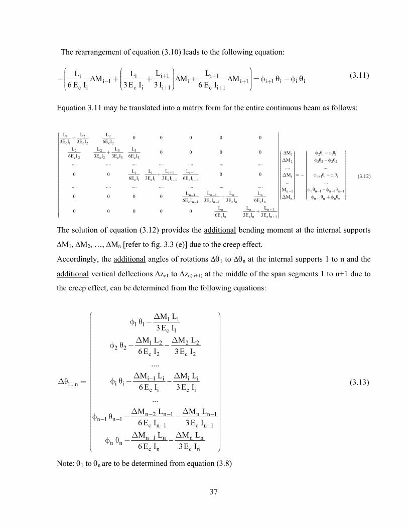
æ öæ ö ÷ç ÷ç ÷÷ç- + + = f -fç ÷÷ç ç ÷÷ç ÷ç è øè ø (3.11)
Equation 3.11 may be translated into a matrix form for the entire continuous beam as follows:
1 2 2
c 1 c 2 c 2
3 32 2
c 2 c 2 c 3 c 3
i 1 i 1i i
c i c i c i 1 c i 1
n 1 n 1 n n
c n 1 c n 1 c n c n
L L L0 0 0 0 0
3E I 3E I 6E I
L LL L0 0 0 0
6E I 3E I 3E I 6E I
.... .... .... .... .... .... ....
L LL L0 0 0 0
6E I 3E I 3E I 6E I
.... .... .... .... .... .... ....
L L L L0 0 0 0
6E I 3E I 3E I 6E I
0 0
+ +
+ +
- -
- -
+
+
+
+
1
2
i
n 1
n
n 1n n
c n c n c n 1
M
....
M
...
M
M
LL L0 0 0
6E I 3E I 3E I
-
+
+
æ ö÷ç ÷ç ÷ç ÷ç ÷ç ÷ç ÷÷ç ÷ç ÷ç æ ö÷ç ÷÷çç ÷÷çç ÷÷çç ÷÷ Dç ÷÷ç ç ÷÷ç ç ÷÷ç ÷÷çç ÷÷çç ÷÷çç ÷÷çç ÷÷çç ÷÷ Dç ÷÷ç ç ÷÷ç ÷÷çç ÷÷çç ÷÷çç ÷÷çç ÷÷çç ÷÷ç ÷÷ç ç ÷÷ç ç ÷÷ç ÷çç ÷çDç è ø÷ç ÷ç ÷÷ç ÷ç ÷ç ÷ç ÷ç ÷+ç ÷ç ÷çè ø
2 1 1 1
3 2 2 2
i 1 i i i
n n 1 n 1 n 1
n 1 n n n
....
...
+
- - -
+
æ öf q f q ÷ç ÷ç ÷ç ÷f q f qç ÷ç ÷ç ÷÷ç ÷ç ÷ç ÷ç ÷ç ÷f q f q= - ç ÷ç ÷÷ç ÷ç ÷ç ÷ç ÷ç ÷ç ÷f q f qç ÷ç ÷÷÷ ç ÷÷ ç ÷f q + f qè ø
(3.12)
The solution of equation (3.12) provides the additional bending moment at the internal supports
M1, M2, …, Mn [refer to fig. 3.3 (e)] due to the creep effect.
Accordingly, the additional angles of rotations 1 to n at the internal supports 1 to n and the
additional vertical deflections zc1 to zc(n+1) at the middle of the span segments 1 to n+1 due to
the creep effect, can be determined from the following equations:
1 11 1
c 1
1 2 2 22 2
c 2 c 2
i 1 i i ii i1...n
c i c i
n 2 n 1 n n 1n 1 n 1
c n 1 c n 1
n 1 n n nn n
c n c n
M L
3 I
M L M L
6 I 3 I
....
M L M L
6 I 3 I
...
M L M L
6 I 3 I
M L M L
6 I 3 I
-
- - -- -
- -
-
æ Dç f q -çç
D Df q -
D Df q -Dq =
D Df q -
D Df q -
è
ö÷÷÷÷ç ÷ç ÷ç ÷ç ÷÷ç ÷ç ÷ç ÷ç ÷ç ÷ç ÷ç ÷÷ç ÷ç ÷ç ÷ç ÷ç ÷ç ÷ç ÷ç ÷÷ç ÷ç ÷ç ÷ç ÷ç ÷ç ÷ç ÷ç ÷÷ç ÷ç ÷ç ÷ç ÷ç ÷ç ÷ç ÷ç ÷÷ç ø
(3.13)
Note: 1 to n are to be determined from equation (3.8)

38
( )
( )
21 1
1 c1c 1
2 21 2 1 2
2 c2c 2 c 2
2 2i 1 i i i
i cic1...c n 1c i c i
2 2n 1 n n n
n cnc n c n
2n n 1
n 1 c n 1c n 1
M LZ
16 I
M L M LZ
16 I 16 I
....
M L M Lz Z
16 I 16 I
...
M L M LZ
16 I 16 I
M LZ
16 I
-+
-
++ +
+
Df
D Df -
D DD = f -
D Df -
Df -
æ ö÷ç ÷ç ÷ç ÷ç ÷ç ÷ç ÷ç ÷÷ç ÷ç ÷ç ÷ç ÷ç ÷ç ÷ç ÷÷ç ÷ç ÷ç ÷ç ÷ç ÷ç ÷ç ÷ç ÷÷ç ÷ç ÷ç ÷ç ÷ç ÷ç ÷ç ÷ç ÷÷ç ÷ç ÷ç ÷ç ÷ç ÷ç ÷ç ÷ç ÷÷ç ÷ç ÷ç ÷ç ÷çè ø
(3.14)
Note: zc1 to zc(n+1) are to be determined from equation (3.9)
Case of a continuous beam with constant creep coefficient:
In the special case where the creep coefficient for all beam segments are equal, the values of all
elements of the matrix on the right hand side of equation (3.12) will be equal to zero.
Accordingly, the solution of equation (3.12) in this particular case will require that M1 to Mn
must be equal to zero. This means that the creep will not lead to any change of the bending
moments. From equations (3.13) and (3.14), the additional deflection line of the beam due to
creep will be affine with the elastic deflection line and the affinity factor will be equal to the
creep coefficient. This case is comparable with the results of the bending moment calculations for
the continuous beam shown in fig. 3.3(a) if the moment of inertias of the beam cross section are
reduced by a constant factor. The bending moments shown in fig. 3.3(b) will remain unchanged
but the elastic deflection line shown in fig. 3.3(d) will be scaled up based on the said reduction
factor of the moment of inertias. A further study for the effect of creep on continuous beams
leads to the conclusion that in case only one span of the continuous beam creeps, bending
moments will be induced in the entire length of the continuous beam. Fig. 3.3(f) shows the
bending moment distribution resulting from the creep of the beam segment between the internal
supports (i) and (i+1) only. This case may be experienced in practice if for example one span of
the continuous beam is built out of concrete while all other spans are built with steel or if one

39
span is built with in-situ concrete while all other spans are built with relatively old precast
concrete segments.
The above study of the effect of creep on continuous beam highlights the benefit of selecting the
stay cable forces to get the deck to behave as a continuous beam as if there were rigid supports at
the anchorage points of each stay cable at the deck level. The benefit of using precast segmental
construction with low uniform creep coefficients and uniform elastic modulus, can be also
understood from the above explanation.
Going back to fig. 3.1, it can be understood that the downward creep which would have taken
place for each deck segment due to the dead load W is counterbalanced by the upward creep due
to the selected stay cable forces using the continuous beam method. It should be further noted
that the desired results shown in fig. 3.1, will be more accurately obtained if the compression
elements of the deck and the pylons are built longer to compensate the axial elastic shortening
due to the normal forces and to compensate in addition the axial shortening resulting from the
time dependent creep and shrinkage effects. For further clarifications on the use of the continuous
beam method for the determination of the desired stay cable forces under dead load, refer to the
numerical example under Appendix A.

40
fig. 3.3: Creep effect on a continuous concrete beam

41
After the calculation of the theoretical desired stay cable forces by the continuous beam method,
it will be explained hereafter how to achieve these desired forces in reality. At the time of the stay
cable installation during construction, the structural system will be different from the structural
system of the completed bridge and the acting loads are different from the dead load at end of
construction. Therefore, it is necessary for the achievement of the desired end results for the
completed structure under dead load, to install the stay cables “to length”. This means that the
unstressed length of the stay cable at the time of installation should be equal to the unstressed
length of the stay cable for the completed structure. From fig. 3.1, the unstressed length Lui for
any cable may be calculated by using the following formula:
i iui
i Di
s si
L LL
(1 ) F1
E A
= =æ ö+ e ÷ç ÷+ç ÷ç ÷çè ø
(3.15)
where: Li = the stressed length of the stay cable i, in the completed structure configuration, at time infinity (when all creep and shrinkage effects have taken place)
FDi = the desired stay cable force under dead load at time infinity
i = is the elastic strain of the stay cable under the effect of the cable force FDi
si = the cross sectional area of the stay cable i.
The installation of the stay cable “to length” as per formula 3.15 will help to achieve the desired
stay cable forces at time infinity under dead load and the bending moment distribution shown in
fig. 3.1. Further, the installation of the stay cables “to length” provides the contractor with the
flexibility to:
- Select any of the construction methods shown in fig. 3.4 which would suit the prevailing site
conditions, the available construction tools/equipments and the available labor expertise.
- Adopt any construction sequence for the deck, pylon elements and stay cables installation as
long as the adopted sequence would have no adverse effect on the integrity of the structure. The
contractor would also be able to change the previously planned construction sequence at a later
stage during construction due to any unforeseen reasons, if the need arises.
- Change the temporary construction loads, like weights of cranes, erection machines, cable coils
etc. if deemed necessary provided that the adequacy of the structural elements will be checked
at all construction stages.
- Introduce and remove of temporary trestles and/or temporary stay cables wherever required.

42
(a) Balanced cantilever method - Rion Antirion (b) Progressive placement method bridge in Greece [http://en.structurae.de] (Sungai Prai bridge in Malaysia)
(c) Deck construction on scaffolding (Wazirabad bridge in India)
fig 3.4: Common construction methods for cable-stayed bridges
3.2 The “bending moment envelope for live loads” method
The continuous beam method explained above for the determination of the stay cable forces at
time infinity under dead load, is considered by many bridge designers as the best method for
cable-stayed bridges with concrete deck cross sections. This is because the achieved bending
moment distribution, as mentioned above, helps to reduce the creep effect and the related change
in the bridge alignment. For cable-stayed bridges with steel deck cross sections, the continuous
beam method may not be the best method from the economic point of view as stated by H.
Svensson [Svensson 2012]. Fig. 3.5 (a) shows the typical envelope of bending moment
distribution due to live loads for the conventional cable-stayed-bridges. H. Svensson

43
recommended to use the continuous beam method only in case of concrete deck section.
Accordingly, the behavior of the concrete deck under the dead and live loads would follow fig.
3.5 (b). In case the deck is made of steel section and because the steel deck does not creep, the
behavior of the deck under the dead and live loads should follow fig. 3.5 (c).
fig 3.5: Effect of the live load on the selection of the stay cable forces under dead load
[Svensson 2012]
By comparing figs. 3.5 (b) and (c), it can be concluded that the approach proposed by H.
Svensson leads to an economical solution for the steel deck as the required bending moment
capacity of the steel deck section will be less than the maximum bending moment resulting from
the live loads. It should however be noted that the deck elements will have to precambered to
counter the deflection associated with the creation of MDL shown in fig. 3.5(c). Further, this
method leads to higher stay cable forces and consequently higher stay cable quantities as
compared with the corresponding stay cable forces and quantities resulting from the method of
the continuous beam method [fig. 3.5(b)]. The achieved saving in the deck material cost should,
therefore, be compared with the extra cost of the stay cable material, if the method proposed by
H. Svensson is followed.

44
3.3 The method of influence matrix for stay cable forces
The modern versions of the commercial computer soft-ware for bridges analysis/design, may be
used to target specific desired stay cable forces, specific bending moment distribution or to
eliminate the deflection of the deck under dead load at the anchorage points of the stay cables
[Gabrow 2004] [Pedrozzi 2004].
The stay cable force [fig 3.6 (a) ] of cable no. i under dead load is assumed to be equal to Fi (as
calculated by the computer model prior to the application of any shortening of the stay cables).
The desired stay cable force [fig. 3-6 (b)] under dead load is assumed to be equal to FDi which
may simply desired to be equal to [Ws / sin (i)]. By using the computer model, it is possible to
calculate the force in any stay cable resulting from tensioning the stay cable no. i by a force
equal to 1. By repeating this exercise for all of the n-nos. of cables, the following equation can be
written (noting that the square matrix on the left hand side of this equation with its size n x n is
called the influence matrix for stay cable forces):
( )
( )
( )
( ) ( ) ( ) ( )( ) ( )
( )
11 12 1i 1n1 n 1
21 22 2i 2n2 n 1
j1 j2 ji jnj n 1
n 1 1 n 1 2 n 1 i n 1 n 1 n 1 n
n1 n2 nj nnn n 1
f f ... f ... f f
f f ... f ... f f
... ... ... ... ... ... ...
f f ... f ... f f
... ... ... ... ... ... ...
f f ... f ... f f
f f ... f ... f f
-
-
-
- - - - - -
-
æ ö÷ç ÷ç ÷ççççççççççççççççççççççççè ø
( ) ( )
1 D1 1
2 D2 2
j Dj j
(n 1)n 1 D n 1
n Dn n
F F F
F F F
... ...
F F F
... ...
F F F
F F F
-- -
æ ö æ öD -÷ ÷ç ç÷ ÷ç ç÷ ÷ ÷÷ ç ç÷ ÷D -÷ ç ç÷ ÷÷ ç ç÷ ÷÷ ç ç÷ ÷÷ ç ç÷ ÷÷ ÷ ÷ç ç÷ ÷ ÷ç ç÷ ÷ ÷ç ç÷ ÷ ÷D -÷ ç ç÷ ÷=÷ ç ç÷ ÷÷ ç ç÷ ÷÷ ç ç÷ ÷÷ ÷ ÷ç ç÷ ÷ ÷ç ç÷ ÷ç ç÷ ÷ç ç÷ ÷D -÷ ç ç÷÷ ç ç÷÷ ç ç÷÷ ç ç÷÷ ÷ç çD -è ø è ø÷÷
÷÷÷÷÷÷÷÷
(3.16)
where (refer also to fig. 3.6):
n = total nos. of stay cables
FDi = desired stay cable force for the cable no. i under dead load
Fi = stay cable force of the cable no. i under dead load prior to the shortening /re-stressing of
any stay cable by the forces Fi
Fji = force in stay cable no. j due to tensioning the stay cable no. i by a force equal to 1 [fig.
3.6 (c) ]
Fi = required re-stressing force for the stay cable no. i

45
The solution of equation (3.16) provides the necessary re-stressing or de-sstressing forces F1 to
Fn. Upon the completion of the re-stressing or de-stressing of all stay cables by the forces F1 to
Fn, the stay cable force in cable no. i, for example, will be equal to the desired force FDi.
fig 3.6: Application of the “influence matrix for stay cable forces” method to achieve specific
desired stay cable forces under dead load
The “influence matrix for stay cable forces” method can also be used to achieve specific desired
bending moment distribution. In fig 3.7 (a), the bending moment distribution under dead load is
calculated by the computer (prior to the application of any shortening of the stay cables). The
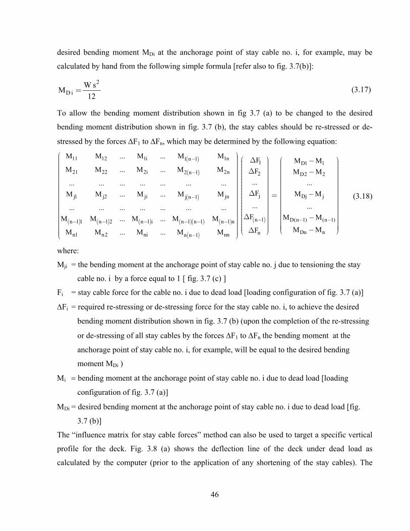
46
desired bending moment MDi at the anchorage point of stay cable no. i, for example, may be
calculated by hand from the following simple formula [refer also to fig. 3.7(b)]:
2
D iW s
M12
=
(3.17)
To allow the bending moment distribution shown in fig 3.7 (a) to be changed to the desired
bending moment distribution shown in fig. 3.7 (b), the stay cables should be re-stressed or de-
stressed by the forces F1 to Fn, which may be determined by the following equation:
( )
( )
( )
( ) ( ) ( ) ( )( ) ( )
( )
11 12 1i 1n1 n 1
21 22 2i 2n2 n 1
j1 j2 ji jnj n 1
n 1 1 n 1 2 n 1 i n 1 n 1 n 1 n
n1 n2 ni nnn n 1
M M ... M ... M M
M M ... M ... M M
... ... ... ... ... ... ...
M M ... M ... M M
... ... ... ... ... ... ...
M M ... M ... M M
M M ... M ... M M
-
-
-
- - - - - -
-
æ ö÷ç ÷ç ÷ççççççççççççççççççççççççè ø
( )
1 D1 1
2 D2 2
j Dj j
n 1 D(n 1) (n 1)
Dn nn
F M M
F M M
... ...
F M M
... ...
F M M
M MF
- - -
æ ö æ öD -÷ ÷ç ç÷ ÷ç÷ ç÷ ÷÷ ç ç÷D ÷-÷ ç ç÷ ÷÷ ç ç÷ ÷÷ ç ÷ ç ÷÷ ÷ç ÷ç÷ ÷ç ÷ç÷ ÷ ÷ç÷ ç÷ ÷ç÷ ç÷ ÷÷ Dç -ç÷ = ÷÷ ç ç÷ ÷÷ ç ÷ ç ÷÷ ç ÷ ç ÷÷ ÷ç ÷ç÷ ÷ ÷ç÷ ç÷ ÷ç÷ ç÷÷ ç ç÷D÷ -ç ç÷÷ ç ç÷÷ ç ÷ ç÷ ÷ç ç÷ ç÷ç -D è ø÷ è ø÷
÷÷÷÷÷÷÷
(3.18)
where:
Mji = the bending moment at the anchorage point of stay cable no. j due to tensioning the stay
cable no. i by a force equal to 1 [ fig. 3.7 (c) ]
Fi = stay cable force for the cable no. i due to dead load [loading configuration of fig. 3.7 (a)]
Fi = required re-stressing or de-stressing force for the stay cable no. i, to achieve the desired
bending moment distribution shown in fig. 3.7 (b) (upon the completion of the re-stressing
or de-stressing of all stay cables by the forces F1 to Fn the bending moment at the
anchorage point of stay cable no. i, for example, will be equal to the desired bending
moment MDi )
i bending moment at the anchorage point of stay cable no. i due to dead load [loading
configuration of fig. 3.7 (a)]
Di = desired bending moment at the anchorage point of stay cable no. i due to dead load [fig.
3.7 (b)]
The “influence matrix for stay cable forces” method can also be used to target a specific vertical
profile for the deck. Fig. 3.8 (a) shows the deflection line of the deck under dead load as
calculated by the computer (prior to the application of any shortening of the stay cables). The

47
desired vertical profile of the deck under dead load is shown in fig 3.8 (b) where the vertical
deflection at the anchorage points of the stay cables are equal to zero.
To allow the vertical profile shown in fig 3.8 (a) to be changed to the desired vertical profile
shown in fig. 3.8 (b), the stay cable forces should be re-stressed or de-stressed by the forces F1
to Fn, which may be determined by the following equation:
( )
( )
( ) ( ) ( ) ( )( ) ( )
( )
11 12 1i 1n1 n 1
21 22 2i 2n2 n 1
j1 j2 ji j(n 1) jn
n 1 1 n 1 2 n 1 i n 1 n 1 n 1 n
n1 n2 ni n nn n 1
Z Z ... Z ... Z Z
Z Z ... Z ... Z Z
... ... ... ... ... ... ...
Z Z ... Z ... Z Z
... ... ... ... ... ... ...
Z Z ... Z ... Z Z
Z Z ... Z ... Z Z
-
-
-
- - - - - -
-
æ ö÷çççççççççççççççççççççççççè ø
( ) ( )
1 1
2 2
j j
n 1 n 1
n n
F Z
F Z
... ...
F Z
... ...
F Z
F Z
- -
æ ö æ öD D÷ ÷ ÷ç ç÷ ÷ ÷ç ç÷ ÷ ÷ç ç÷ ÷ ÷D Dç ç÷ ÷ ÷÷ ç ç÷ ÷÷ ç ç÷ ÷÷ ç ç÷ ÷÷ ÷ ÷ç ç÷ ÷ ÷ç ç÷ ÷ ÷ç ç÷ ÷ ÷D Dç ç÷ ÷ ÷=ç ç÷ ÷ ÷÷ ç ç÷ ÷÷ ç ç÷ ÷÷ ÷ ÷ç ç÷ ÷ ÷ç ç÷ ÷ ÷ç ç÷ ÷ ÷ç ç÷ ÷ ÷D Dç ç÷ ÷ ÷÷ ç ç÷ ÷÷ ç ç÷ ÷÷ ç ç÷ ÷÷ ÷ ÷ç çD Dè ø è ø÷÷
(3.19)
where:
Zji = the vertical deflection at the anchorage point of stay cable no. j due to tensioning the stay
cable no. i by a force equal to 1 [fig. 3.8 (c) ]
Fi = stay cable force for the cable no. i due to dead load [loading configuration of fig. 3.8 (a)]
Zi = the vertical deflection at the anchorage point i due to dead load [loading configuration of
fig. 3.8 (a)]
i = 0.0 - Zi
Fi = required re-stressing or de-stressing force for stay cable i, to achieve the desired vertical
profile shown in fig. 3.8 (b) (upon the completion of the re-stressing or de-stressing of all
stay cables by the forces F1 to Fn, the deflection of the deck at the anchorage points of
the stay cables will be equal to 0.0 as shown in fig. 3.8(b)
From the above explanation, it can be concluded that “influence matrix for stay cable forces”
method may be used to achieve combinations of desired stay cable forces, desired bending
moments and desired deformations at specific locations. The nos. of the desired stay cable forces,
bending moments and deflections (i.e. the nos. of the unknowns), should however be equal to the
nos. of the stay cables n.

48
fig 3.7: Application of the “influence matrix for stay cable forces” method to achieve a specific desired bending moment distribution along the deck length under dead load

49
fig 3.8: Application of the “influence matrix for stay cable forces” method to achieve a specific desired vertical profile for the deck under dead load

50

51
CHAPTER 4
4- CONSTRUCTION ANALYSIS OF BRIDGES WITH COMPOSITE DECKS
As explained in Chapter 3 the stay cables for conventional cable-stayed bridges with concrete
decks are normally installed in such a way that the deck under dead load will not deflect
vertically. Accordingly, the bending moment distribution along the deck length will be similar to
the bending moment distribution of a continuous beam on rigid supports and, therefore, the effect
of creep is eliminated and the achieved desired alignment does not change with time. The stay
cables may then be installed to predetermined unstressed lengths Lu to achieve the desired
alignment and the desired bending moment distribution under dead load regardless of the
construction method/sequence.
For bridges with composite deck cross sections (concrete/concrete or steel/concrete), the
installation of the cables to predetermined lengths, similar to the case of conventional cable-
stayed bridges with concrete-only sections or steel-only sections, does not lead necessarily to the
desired forces and alignment under dead load. The achievement of the desired results will be
influenced by the time dependant forces due to the creep and shrinkage effects of the concrete
parts of the composite section as will be explained in Section 4-1.
It will be also illustrated within sections 4-2 and 4-3 that the desired results will be dependent on
the method of construction of the composite section (i.e. whether the components of the
composite section will be constructed in a single stage or two stages) and the ratio of the moment
of inertia of the first part of the composite section Is to the moment of inertia of the total
composite section Icomp. Further, the desired results will depend on the vertical shift “e” between
the center of gravity of the first part of the composite section and the center of gravity of the total
composite section.
A practical method will be proposed in Section 4-3, which may be followed during the design
stage and during construction, to ensure the achievement of the desired results for the completed
bridge at time infinity taking into account the effects of the ratio “Is / Icomp”, the vertical shift e
and the time dependant forces due to creep and shrinkage of the concrete material.

52
4-1 Time dependent effects on bridge structures with composite decks
For bridge structures with composite decks, the following two types of the time dependent effects
should be studied to achieve the desired forces and alignment under dead load for the completed
bridge:
- Time dependent forces and deformations due to the creep effect resulting from the vertical dead
load and the vertical components of the stay cable forces (Type I).
- Additional time dependent effect resulting from the creep and shrinkage of the concrete
elements of the composite section. Restraining this type of creep and shrinkage by the non-
concrete elements of the composite section, leads to internal eccentric horizontal forces within
the composite section elements and consequently result in a change in the stay cable forces and
leads also to vertical deformation of the bridge structure. This type of creep and shrinkage effect
will be referred to as time dependant effect (Type II).
The extent/magnitudes of the creep and shrinkage strains for any time interval t depend mainly
on the following parameters [Ghali and Favre 1994]:
- The characteristic compressive strength of concrete at the age of 28-days.
- The relative humidity of the ambient environment.
- The notional size of the deck section which is equal to twice the cross sectional area of the deck
section divided by the perimeter in contact with atmosphere.
- Type of cement used for the concrete mix.
- Age of concrete at the beginning of shrinkage.
- Age of concrete at the time of first loading.
4-1-1 Time dependent effect due to vertical loads (Type I)
If the stay cable forces under dead load FDi [fig. 4.1 (a)] are selected in such a way that the
vertical component of each stay cable force [FDi sin (i)] is equal to the corresponding vertical
reaction force Ri for an equivalent imaginary continuous beam fig. 4.1 (b), the creep effect due to
the combination of the dead load and the vertical components of the selected stay cable forces, at
the anchorage points of the stay cables will be eliminated [refer to the deck profile shown in fig.
4.1 (c) ]. In case [FDi sin (i)] is selected higher than the reaction force Ri , the deck profile for the
completed bridge will be similar to that shown in fig. 4.1 (d) and the level of the anchorage points

53
of the stay cables will change with time. Fig. 4.1 (e) shows the deck profile and the direction of
the creep effect in case [FDi sin (i)] is selected less than Ri.
4-1-2 Additional time dependent effect in case of a composite deck (Type II)
In case of a steel/concrete composite section, the creep and shrinkage of the concrete part of the
composite section will be restrained by the steel part and internal eccentric horizontal forces will,
therefore, be induced in the composite section. The internal restraint will also take place in case
of concrete/concrete composite section if the concrete components are of different ages and
different loading histories.
For a composite deck cross section consisting of a steel beam and a concrete slab as that shown in
fig. 4.2 (a) and if the normal force distribution “NFD” acting on the deck is similar to that shown
in fig. 4.2 (b), the concrete slab will tend to creep and shrink and internal eccentric horizontal
forces will be induced between the elements of the composite section accordingly. The creep and
shrinkage strains of the concrete material (C-cr and C-sh) for each deck element can be estimated
from the normal force distribution shown in fig. 4.2 (b) and also from the above mentioned
factors affecting the extent of creep and shrinkage.
Based on the estimated values of (C-cr and C-sh)i for each deck element, the creep and shrinkage
effects of the concrete elements of the composite section may be replaced by a normal
compression force Nri acting at the centre of gravity of the concrete section. The value of Nri may
be determined from the following equation:
( )ri C cr C sh CiN E B t- -= + (4.1)
where B and t are the width and the thickness of the concrete slab and Ec is the elastic modulus of
the concrete material.
If the bridge ends are assumed to be fully restrained against the movement and rotation as shown
in fig. 4.2 (c) and the internal compression force Nri is applied on the deck elements at the center
of gravity of the concrete slab, the reaction forces at the imaginary end supports at the level of the
center of gravity of the composite section will be equal to Nr (tension force) and Mr (hog bending
moment), noting that Mr can be calculated from the following equation [Iles 1989 ]:
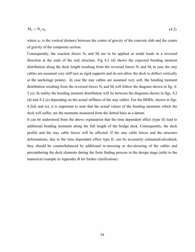
54
r r CM N e= (4.2)
where eC is the vertical distance between the centre of gravity of the concrete slab and the centre
of gravity of the composite section.
Consequently, the reaction forces Nr and Mr are to be applied as nodal loads in a reversed
direction at the ends of the real structure. Fig 4.2 (d) shows the expected bending moment
distribution along the deck length resulting from the reversed forces Nr and Mr in case the stay
cables are assumed very stiff (act as rigid supports and do not allow the deck to deflect vertically
at the anchorage points). In case the stay cables are assumed very soft, the bending moment
distribution resulting from the reversed forces Nr and Mr will follow the diagram shown in fig. 4-
2 (e). In reality the bending moment distribution will lie between the diagrams shown in figs. 4.2
(d) and 4-2 (e) depending on the actual stiffness of the stay cables. For the BMDs. shown in figs.
4.2(d) and (e), it is important to note that the actual values of the bending moments which the
deck will suffer, are the moments measured from the dotted lines as a datum.
It can be understood from the above explanation that the time dependent effect (type II) lead to
additional bending moments along the full length of the bridge deck. Consequently, the deck
profile and the stay cable forces will be affected. If the stay cable forces and the structure
deformations, due to the time dependant effect type II, can be accurately estimated/calculated,
they should be counterbalanced by additional re-stressing or des-stressing of the cables and
precambering the deck elements during the form finding process in the design stage (refer to the
numerical example in Appendix B for further clarification).
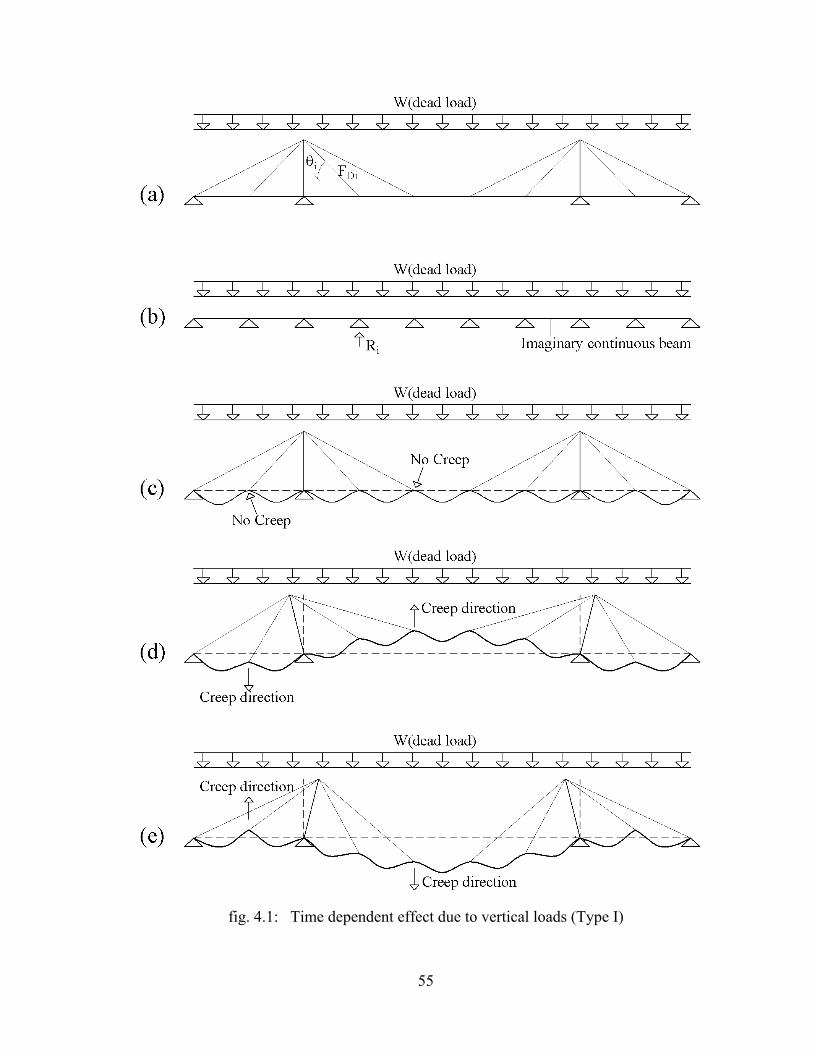
55
fig. 4.1: Time dependent effect due to vertical loads (Type I)

56
fig. 4.2: Additional time dependent effect in case of composite deck (Type II)

57
4-2 Construction stage analysis of cable-stayed bridges with concrete-only or steel-only
deck section
For cable-stayed bridges with deck cross sections made of concrete-only, it is normally
recommended to install the stay cables to specific predetermined unstressed lengths Lui (fig. 4.3)
so that a bending moment distribution is achieved, similar to that shown within fig. 3.1. By
installing the individual stay cables to the calculated “unstressed length” Lui as per the formula
shown in fig. 4.3 (c) and by constructing every new deck and pylon segment tangential to the
previously constructed segment, the desired alignment and forces for the completed structure
under dead load can be obtained provided that the integrity of the structure is examined at each
construction stage. It is also to note that the deck and pylon elements/segments have to be built
longer to compensate the elastic axial shortening due to the normal forces shown within fig. 3.1
and to compensate also the axial shortening due to the time dependant forces resulting from the
shrinkage and creep effects.
fig. 4.3: Installation of stay cables to “length”
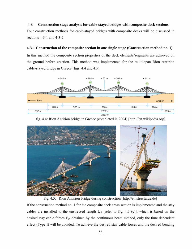
58
4-3 Construction stage analysis for cable-stayed bridges with composite deck sections
Four construction methods for cable-stayed bridges with composite decks will be discussed in
sections 4-3-1 and 4-3-2
4-3-1 Construction of the composite section in one single stage (Construction method no. 1)
In this method the composite section properties of the deck elements/segments are achieved on
the ground before erection. This method was implemented for the multi-span Rion Antirion
cable-stayed bridge in Greece (figs. 4.4 and 4.5).
fig. 4.4: Rion Antirion bridge in Greece (completed in 2004) [http://en.wikipedia.org]
fig. 4.5: Rion Antirion bridge during construction [http://en.structurae.de]
If the construction method no. 1 for the composite deck cross section is implemented and the stay
cables are installed to the unstressed length Lui [refer to fig. 4.3 (c)], which is based on the
desired stay cable forces FDi obtained by the continuous beam method, only the time dependent
effect (Type I) will be avoided. To achieve the desired stay cable forces and the desired bending

59
moment distribution, similar to that shown within fig. 3.1, the time dependent effect (Type II) has
to be taken into account (refer to Section 4.1). The stay cable forces will have to be re-stressed or
de-stressed to eliminate the changes resulting from the time dependent effect (Type II). The
deformations resulting from the time dependant effect (type II) should also be accounted for
during the calculations of the required precamber for the deck and the pylon elements (refer also
to Appendix B).
The construction method no. 1 described above, cannot always be implemented as they require
cranes with heavy lifting capacities which are very often not available. Many contractors prefer to
handle the components of the composite sections (steel + concrete) or (concrete + concrete)
separately as shown in figs. 1.2 and 1.3.
If the components of the composite section are to be constructed in two stages, three construction
methods may be investigated which will be referred to as construction methods 2, 3 and 4 to
differentiate them from the above described construction method no. 1.
4-3-2 Construction of the composite cross section in two stages (Construction methods nos.
2,3 and 4)
fig. 4.6: Construction methods for composite section in two stages (schematic) [Schlaich 2001]
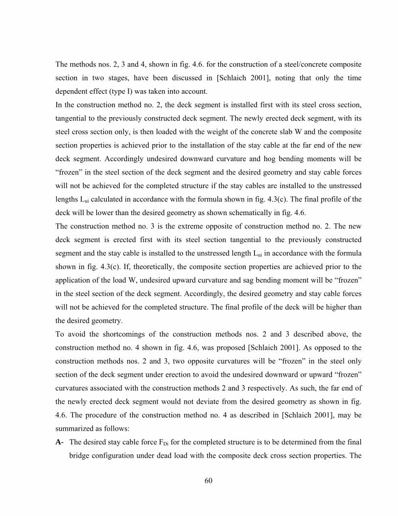
60
The methods nos. 2, 3 and 4, shown in fig. 4.6. for the construction of a steel/concrete composite
section in two stages, have been discussed in [Schlaich 2001], noting that only the time
dependent effect (type I) was taken into account.
In the construction method no. 2, the deck segment is installed first with its steel cross section,
tangential to the previously constructed deck segment. The newly erected deck segment, with its
steel cross section only, is then loaded with the weight of the concrete slab W and the composite
section properties is achieved prior to the installation of the stay cable at the far end of the new
deck segment. Accordingly undesired downward curvature and hog bending moments will be
“frozen” in the steel section of the deck segment and the desired geometry and stay cable forces
will not be achieved for the completed structure if the stay cables are installed to the unstressed
lengths Lui calculated in accordance with the formula shown in fig. 4.3(c). The final profile of the
deck will be lower than the desired geometry as shown schematically in fig. 4.6.
The construction method no. 3 is the extreme opposite of construction method no. 2. The new
deck segment is erected first with its steel section tangential to the previously constructed
segment and the stay cable is installed to the unstressed length Lui in accordance with the formula
shown in fig. 4.3(c). If, theoretically, the composite section properties are achieved prior to the
application of the load W, undesired upward curvature and sag bending moment will be “frozen”
in the steel section of the deck segment. Accordingly, the desired geometry and stay cable forces
will not be achieved for the completed structure. The final profile of the deck will be higher than
the desired geometry.
To avoid the shortcomings of the construction methods nos. 2 and 3 described above, the
construction method no. 4 shown in fig. 4.6, was proposed [Schlaich 2001]. As opposed to the
construction methods nos. 2 and 3, two opposite curvatures will be “frozen” in the steel only
section of the deck segment under erection to avoid the undesired downward or upward “frozen”
curvatures associated with the construction methods 2 and 3 respectively. As such, the far end of
the newly erected deck segment would not deviate from the desired geometry as shown in fig.
4.6. The procedure of the construction method no. 4 as described in [Schlaich 2001], may be
summarized as follows:
A- The desired stay cable force FDi for the completed structure is to be determined from the final
bridge configuration under dead load with the composite deck cross section properties. The

61
continuous beam method may be used to calculate the desired stay cable forces under dead
load FDi and the unstressed length Lui for each individual cable is to be determined as per the
formula shown in fig. 4.3 (c).
B- As shown in fig. 4.7, the typical erection cycle for a deck segment starts with the
construction of the first part of the composite section (steel only section), tangential to the
previously constructed deck segment (Note: the deck segments are shown horizontal for
simplicity). Further, each stay cable will have to be installed in two stages as will be
explained below.
C- The steel cross section of the deck segment under erection is to be loaded with the weight of
the second part of the composite section (i.e. the weight of the concrete slab). The first stage
installation force of the stay cable, prior to the achievement of the composite cross section
properties, should be determined in such a way that the bending moment distribution along
the new deck segment with its steel only cross section, will be similar in shape to that shown
in fig. 4.7 (the “frozen” bending moment), noting that “e” is equal to the vertical distance
between the center of gravity of the steel only section and the center of gravity of the total
composite section. The “frozen” bending moment distribution shown in fig. 4.7, will lead to
two opposite “frozen” curvatures in the steel section of the deck segment prior to the
achievement of the composite section properties.
fig. 4.7: Bending moment distribution along the deck segment under erection prior to the
achievement of the composite section properties [Schlaich 2001]

62
D- Upon the achievement of the composite section properties, the stay cables are to be re-
stressed “to length” so that the unstressed length of the stay cable will be equal to the
unstressed length Lui calculated under point “A” above.
Further investigations for the construction method no. 4 described above, have been carried out
and it was found that the desired stay cable forces and the desired geometry for the completed
structure under dead load, will be achieved provided that:
- The time dependent effect (Type II) may be ignored (if, for example, very old precast segments
are planned to be used).
- The ratio between the moment of inertia of the first part of the composite section Is and the
moment of inertia of the total composite section Icomp , is relatively high (refer to Appendices
C and D).
- The vertical shift between the center of gravity of the first part of the composite section and the
center of gravity of the total composite section “e” is negligible.
To understand the influence of the parameters Is / Icomp and “e” on the desired forces and
geometry for the completed structure under dead load, two models for the typical erection cycle
of construction methods nos. 1 and 4 are investigated and compared as shown in fig. 4.8.
In this study it will be shown that the achievement of the same stay cable force at the end of the
typical erection cycle of construction methods (1) and (4), will not lead to the same relative
vertical deflection between the two ends of the deck segment under erection. Further the angles
of rotations of the deck profiles at the far end of the deck segments under erection, will not be
equal for both of the construction methods (1) and (4). In other words, it will be concluded from
this study that it is impossible to achieve the same stay cable forces at the end of the erection
cycle of construction methods nos. (1) and (4), if the stay cables are installed to the same
unstressed length Lui.

63
fig. 4.8: Comparison between the erection cycle of construction methods nos. (1) and (4)
The following points should be noted concerning the content of fig. 4.8:
- The time dependent effect (type II) is ignored for both of construction methods (1) and (4).
- Es is the elastic modulus of the idealized section of the two parts of the composite section (the
area and the moment of inertia of the concrete section are transferred to equivalent steel area
and moment of inertia based on the ratio between the elastic modulus of the concrete to the
elastic modulus of steel).
- Is and Icomp are the moment of inertia of the first part of the composite section and the moment
of inertia of the total composite section respectively (expressed in the idealized steel unit).
- In construction method no. (1), the composite section properties are achieved before the
erection of the segment AB (similar to the erection method used for Rion Antirion bridge fig.
4.5). As such, the desired geometry and the desired cable forces will be achieved for the
completed structure if the cables are installed to the unstressed length Lui [fig. 4.3(c)], noting
that the time dependent effect type II is ignored.

64
- In Method no. (4), the composite section properties are achieved after the erection of the
segment AB.
- F1 is the force required in construction method (4) to get the relative vertical deflection between
points A and B to be equal to zero, noting that the structural system between points A and B at
the time of the application of the force F1, is a determinate structural system.
The relative vertical deflection between the two ends A and B of the segment under erection is
caused by the external load W and the cable force F1. From the above mentioned definition of
the force F1, it may be calculated by solving the following equation:
3 241 1
s s s s s s
F sin ( ) L F cos ( ) e LW L
8 E I 3 E I 2 E I
q q=
(4.3)
By rearrangement of equation (4-3)
13 W L 1
F3 e8 sin ( )
1 cot ( )2 L
=æ öq ÷ç q ÷ç ÷çè ø
(4.4)
- The force F1 is dependent on the eccentricity "e" [refer to equation (4.4] and fig. 4.7).
- If the cable in construction method (1) is installed also in two stages and the first installation
force is made also equal to the value of the force F1 as defined above , the point B in the case of
construction method (1) will be lower than the point B in case of construction method (4). This
can be concluded by studying the above equation (4.4) of F1, noting that the eccentricity “e” in
the case of construction method no. (1) is equal to zero and therefore the cable force required to
eliminate the relative vertical deflection between the points B and A would be equal to 3/8 W L
/ sin () which is higher than the force F1 in equation no. (4.4).
- After the first stage installation of the cable in construction methods (4) and (1) to the same
cable force F1 calculated from equation (4.4), the absolute value of the angle of rotation of the
deck profile at point B “ |41| “ in case of construction method (4) will be higher than the
absolute value of the corresponding angle at point B “ |11| “ in the case of construction method
(1). This can be concluded by studying the equations of the angles of rotations |41| and |11|
shown in fig. 4.8, noting that the moment of inertia for the composite section Icomp (expressed in
the idealized steel units) is higher than the moment of inertia of the steel section Is (expressed
also in steel units). It is also to be noted that Es is the elastic modulus of the steel material.

65
- After the cable installation in construction method (4) to the force F1, the deck segment under
erection will get the composite section properties and the “frozen” bending moment distribution
in the deck segment under erection will be similar in shape to that shown within fig. 4.7.
- The force F2 is defined from construction method no. (1) which is the cable force after being re-
stressed to the unstressed length Lui [calculated in accordance with the formula shown in fig. 4.3
(c)].
- Upon the achievement of the composite section properties in construction method no. (4), the
effect of the re-stressing of the cable from F1 to F2 on the deck segment AB will be the same in
both of construction methods (4) and (1). This means that at the end of the erection cycle, point
B in case of construction method (4) will remain higher than Point B in case of construction
method (1) and the absolute angle of rotation for the deck profile |42| at point B in case of
construction method (4) will be higher than the corresponding angle of rotation |12| in case of
construction method (1). Accordingly, construction method (4) will lead ultimately to a deck
profile higher than the desired deck profile which would be obtained if construction method (1)
is followed. It can also be concluded that it is impossible to achieve the same stay cable forces
at the end of the erection cycle of construction methods nos. 1 and 4, if the stay cables are
installed to the same unstressed length Lui. Accordingly construction method (4) cannot be
followed, without modification, if both of the desired stay cable forces and the desired geometry
are required to be achieved for the completed structure under dead load.

66
4-3-3 Application of the construction methods 2,3 and 4 on a simple cables supported beam
In this section the construction methods nos. 2, 3 and 4 described above under Section 4-3-2 will
be applied on the cables supported beam shown in fig. 4.9. It will be explained in this study that
the installation of stay cables to the unstressed length Lui, in accordance with the formula shown
in fig. 4.3 (c), will not lead to the desired forces and the desired geometry for the completed
structure if any of the construction methods 2,3 or 4 is followed. In Section 4-3-4, a new method
will be proposed (construction method no. 5) to achieve the desired forces and geometry.
fig. 4.9: Cable supported beam with a rectangular cross section constructed in two stages
The desired bending moment distribution under dead load is shown in fig. 4.9 (b). The cable
forces leading to this bending moment distribution are assumed to be equal to FD1 to FD4 and the
corresponding unstressed lengths of the cables are assumed to be equal to Lu1 to Lu4 (noting that
the time dependent effect type (II) will be ignored in this study) .
Fig. 4.10 shows the erection stages for the two extreme construction methods nos. 2 and 3
described above. In construction method no. 2, fig. 4.10 (a to c), the beam is constructed in
4‐stages with four equal lengths. All the segments are constructed tangential to the previously
constructed segments. Each beam segment is constructed first with its “part 1” shown within fig.

67
4.9(a). By casting the remaining part of the beam section (part 2 of the cross section), part 1 of
the cross section will have to carry its own weight and in addition the concrete weight of part 2.
Accordingly, a relatively big downward deflection and hog bending moment will be “frozen”
within part 1 of the beam cross section. Upon the hardening of the newly cast concrete of part 2
of the cross section, the cables are installed with the unstressed lengths Lu1 to Lu4.
In construction method no. 3, fig. 4.10 (f to h), the beam is constructed also in 4‐stages with 4-
segments equal in length. Each segment is constructed first with its first part of the composite
section [refer to part 1 of the cross section shown within fig. 4.9(a)] tangential to the previously
constructed segments. The cables are then installed to the unstressed lengths Lu1 to Lu4, prior to
the application of the external uniform load W. If it is assumed theoretically that the composite
section properties are achieved in the absence of the weight W, a relatively big upward deflection
and sag bending moment will be “frozen” within part 1 of the beam cross section before the
achievement of the composite section properties.
Computer models have been established to study the results for both of the construction methods
nos. 2 and 3. The computer results show, as expected, that the cable forces for the completed
structure for construction method no. 2, are higher than the corresponding desired forces FD1 to
FD4. For construction method no. 3, the cable forces for the completed structure are less than the
desired forces FD1 to FD4.
Fig. 4.10 (d , e, i and j) show also the resulting vertical deflection and bending moment diagrams
for both of the construction methods nos. 2 and 3 for the completed structure (when all cables are
already installed to the unstressed lengths Lu1 to Lu4), which are not similar to the desired results
(refer to fig. 4.9(b) ). Accordingly it can be concluded that if the beam cross section is
constructed in two stages [as it is the case for both of construction methods (2) and (3)], the
installations of the cables to the unstressed lengths Lu1 to Lu4, do not lead to the desired alignment
and the desired forces within the structural elements for the completed structure.
Further, it can be seen from fig. 4.10(e) that the beam elements in construction method no. (2)
have to carry excessive sag bending moment due to the following reason:
‐ The beam elements get extra downward deflection due to the fact that their “part 1” of the
composite section shown in fig. 4.9 (a), carried the external uniform load prior to the cable
installation.
‐ Due to the extra downward deflection of the beam elements, extra cable forces have to be

68
carried by the beam as the cables are installed to the predetermined unstressed lengths Lu1 to
Lu4. The extra cable forces lead to the above mentioned excessive sag bending moment.
Similarly, the excessive hog bending moment shown within fig. 4.10 (j) for construction method
no. 3, can be justified as follows:
‐ The beam elements get extra upward deflection due to the fact that their “part 1” of the
composite section carried the vertical component of the installation cable force prior to the
achievement of the composite section properties.
- Due to the extra upward deflection of the beam elements, less cable forces will be introduced to
the structure when the cables are installed to the predetermined unstressed lengths Lu1 to Lu4
and, therefore, the hog bending moment acting on the beam elements due to the external
uniform load W will be higher.
It should now be noted that the bending moment shown within fig. 4.10 (e) for construction
method no. 2 may be corrected to be similar to the desired bending moment diagram shown
within fig. 4.9 (b) provided that the cable forces are de‐stressed to “FD1 to FD4”. By de‐stressing
the cable forces this way, both of the desired bending moment diagram and the cable forces are
achieved but the desired vertical profile of the beam elements will not be achieved noting that
extra downward deflection will be added to the vertical deflection shown within fig. 4.10(d). This
problem would however be solved by pre-cambering the beam segments in accordance with the
final vertical deflection line (with opposite sign) upon carrying out the above described
de‐stressing of the cable forces.
Similarly, the bending moment shown within fig. 4.10 (j) for construction method no. 3 may be
corrected to be similar to the desired bending moment diagram shown within fig. 4.9 (b) provided
that the cable forces are re‐stressed to “FD1 to FD4”. By re‐stressing the cable forces this way, both
of the desired bending moment diagram and the cable forces are achieved but the desired vertical
profile of the beam elements will not be achieved noting that extra upward deflection will be
added to the vertical deflection shown within fig. 4.10 (i). This problem would however be
solved by pre-cambering the beam segments in accordance with the final vertical deflection line
(with opposite sign) upon carrying out the above described re‐stressing of the cable forces.

69
fig. 4.10: Application of the construction methods nos. 2 and 3 on a cables supported beam
70
Further to the above, it should be emphasized that although de-stressing or re-stressing of the
cables help to ultimately achieve the desired forces within the beam elements, the problem of the
interim high level of forces/stresses within the beam elements prior to the above mentioned de-
stressing or re-stressing of cables for construction methods nos. 2 and 3 respectively [refer to the
bending moment diagrams of figs. 4.10 (e) and 4.10 (j)], remained unresolved. Following any of
the two extreme construction methods 2 and 3 described above is, therefore, practically not
possible.
The application of construction method no. 4 on the cables supported beam shown in fig. 4.9 (a),
requires the installation of each of the 4-cables in two stages. In the first stage of the cable
installation, the cable is to be tensioned to an initial force F1 to create a bending moment
distribution, similar in shape to that shown within fig. 4.7 which has to be within the capacity of
part 1 of the beam cross section. The initial installation force F1 is dependent on the external
uniform load W and the vertical shift “e” between the C.G of the first part of the beam section
and the C.G of the total composite section [refer to equation (4.4)]. Upon the achievement of the
composite section properties, the second stage of the cable installation (to the unstressed lengths
Lu1 to Lu4) may be carried out. As explained under Section 4.3.2, the results of the computer
model for the cables supported beam shown in fig. 4.9, confirmed that the installations of the
cables to the unstressed lengths Lu1 to Lu4, do not lead to the achievement of the desired
alignments or the desired cable forces at end of construction. The resulting geometry and forces
will be dependent on the ratio Is / Icomp. Computer models have been established to study the
effect of the ratio Is / Icomp on the vertical deflection of the beam, the bending moment distribution
and the cable forces for the completed structure assuming that the cables are installed in two
stages and the final unstressed lengths for the cables are equal to Lu1 to Lu4 [calculated in
accordance with the formula of fig. 4.3(c)]. Figs. 4.11 and 4.12 show, for the particular structure
under investigation, that the high values of the ratio Is / Icomp (above 40%), lead almost to the
desired vertical profile and the desired bending moment distribution for the completed structure.
For Is / Icomp (above 40%) the stay cable forces for the completed structure deviate slightly from
the desired cable forces FD1 to FD4 by about ±5%. The stay cable forces would however deviate
by up to ± 25% in case the ratio Is/Icomp is as low as 5%. Accordingly, it can be concluded that in
case the cables are installed in two stages and the total unstressed lengths of the cables are equal
to Lu1 to Lu4 (after carrying out the two installation stages), the cables may be required to be re-

71
stressed or de-stressed at end of construction to the desired forces FD1 to FD4, in particular when
the ratio Is/Icomp is relatively low. The re-stressing or the de-stressing of the cable forces will help
to achieve the desired cable forces and the desired bending moment for the completed structure.
Further, the beam segments will have to be pre-cambered to achieve the desired alignment for the
completed structure in addition to the achieved desired forces.
fig. 4.11: Effect of the ratio Is / Icomp on the vertical deflection profile for the completed structure
in case the cables are installed “to length” with construction method no. 4
fig.4.12: Effect of the ratio Is / Icomp on the bending moment distribution for the completed
structure in case the cables are installed “to length” with construction method no. 4
72
4-3-4 Proposed modification for the construction method no. 4 (construction method no. 5)
Based on the discussions made under 4-3-1 to 4-3-3, the proposed procedure for the construction
of the cable-stayed bridges with composite decks, may be summarized as follows: (taking into
account the effects of the ratio between the moment of inertia of the first part of the composite
section to the moment of inertia of the total composite section Is / Icomp , the vertical shift “e”
between the center of gravity of the first part of the composite section and the center of gravity of
the total composite section and the time dependant forces due to shrinkage and creep):
a- The desired cable forces FDi under dead load at time infinity (when all time dependant effects
have taken place) are to be determined in such a way that the vertical components of the
cables would be equal to the vertical reaction forces for an equivalent continuous beam on
rigid supports.
b- A computer model is to be established to carry out the “step by step construction stage
analysis” using the actual cross section properties of the deck elements at any particular
construction stage (refer to Section 3-1).
c- Each deck element is to be introduced in the computer model initially with the properties of the
first part of the composite section. The new deck and pylon elements are to be introduced in
the model with initial longer lengths to balance the elastic shortening due to the normal forces
resulting from the horizontal components of the stay cable forces and the normal forces in the
pylon elements at time infinity (this initial length should be taken into account for the
definition of the precamber as will be clarified below). Each stay cable is to be installed to an
initial force in accordance with equation no. (4.4). The use of equation no. (4.4) leads to
“frozen” bending moments distribution for the deck segments under erection, similar in shape
to that shown within fig. (4.7). Subsequently, the properties of the deck cross section are to be
changed to the properties of the composite section. The stay cable is then to be re-stressed “to
length” as explained in construction method no. (4) under Section 4-3-1.
d- Point “c” is to be repeated for all deck segments/cables.
e- The stay cable forces and the structure deformations due to the time dependent effects will be
determined in the computer model (refer to Section 4-1) during construction and till time
infinity. The creep and shrinkage effects are calculated in the computer model in small time
intervals. Partial creep and shrinkage factors for each time interval are considered in the
computer model based on the factors mentioned within Section 4-1. In this connection
73
reference is made to [Ghali and Favre 1994] for more details. The relaxation effect of the stay
cable material may be taken into account in small time intervals as well.
f- The stay cable forces are to be calculated by the computer model upon the erection of all
structural elements and the application of all external loads and after all time dependent effects
have taken place (at time infinity). The calculated stay cable forces at time infinity, using the
“step by step construction stage analysis” by the computer model, will not be equal to the
desired stay cable forces FDi calculated earlier under point “a” above. The reasons of the
difference between the stay cable forces calculated under point “a” and the stay cable forces
calculated by the “step by step computer model analysis”, are explained under sections“4-2”
and “4-3”.
g- Assuming that the change in each cable force between the time infinity and the time of the
construction completion as calculated with the computer model is equal to Fi-∞-0 , the design
force for each stay cable at end of construction should be equal to FDi - Fi-∞-0. Accordingly,
the stay cable forces at end of construction are to be re-stressed or de-stressed to the force:
( FDi - Fi-∞-0).
h- During the design stage, the stay cables are to be re-stressed or de-stressed at time infinity, in
the computer model) to FDi. The vertical and horizontal deflections of the structure elements
should then be calculated at time infinity and precambered accordingly (the initial length of
the deck and pylon segments, as indicated above under point c, should be taken into account
during the definition of the required fabrication length of each element).
To illustrate further the proposed construction method no. (5), refer to the numerical example
under Appendix B.

74
4-3-5 Application of the construction method no. (4) or (5) on cable-stayed bridges with
composite deck sections
The construction method no. (4), as proposed in [Schlaich 2001], was applied previously on a
simple cables supported beam in Section 4-3-3. The same construction method will be applied in
this section on a complete cable-stayed bridge to highlight/resolve additional problems not
covered in the case of the above mentioned cables supported beam.
If the composite deck segments of a cable-stayed bridge are built with the balanced cantilever
method starting from the pylon and the construction method no. (4) is followed, special attention
should be paid in the design stage, during the activation of the end supports and also during the
activation of the closure joint between the two cantilevers of the main span.
As explained under Section 4-3-2, the erection of the deck segments with the construction
method no. (4), does not lead to the same deck profile when compared to the construction method
no. 1. Accordingly, and as shown in fig. 4.13 (a), the deck profile prior to the activation of the
end supports in case the construction method no. (4) is followed, will deviate from the deck
profile of construction method no. 1.
If construction method no. (4) is followed, the tip of the deck at the end supports should be
jacked down in accordance with the vertical deflection and not (Z1 + Z2), otherwise
additional forces will be locked-in between the deck and the end supports and the desired stay
cable forces and bending moment distribution at time infinity will not be achieved.
Similarly, the temporary forces P required to connect the two half of the cable-stayed bridge
tangentially at the closure joint [fig 4.13 (b) and (c)], should be determined from a computer
model assuming that the construction method no. (1) is followed. The choice of the jacking force
at the end supports or the temporary loads at the closure joint in accordance with construction
method no. (1), would lead to the deck profile shown in fig. 4.13 (d) for the completed structure.
By selecting an appropriate pre-camber for the deck, the end supports will be constructed at the
right desired levels and the deck segments at the closure joint will be constructed without a kink.
The above explanation implies that the “step by step construction stage analysis” for a cable-
stayed bridge with composite deck, requires the establishment of two computer models. The first
computer model will consider the erection of the deck segments with the construction method no.
4 and the erection of the deck segments will follow construction method no. 1 in the second
computer model. The first computer model will be used for the determination of the required

75
precamber and also for monitoring the bridge behavior during construction. The second model
will be used to determine the required jacking forces at the end supports or the temporary forces
at the closure joint at the middle of the main span, as explained above.
In Appendix C and Appendix D, the results of the application of the proposed construction
method no. (5) on cable-stayed bridges with composite deck cross sections (steel/concrete) and
(concrete/concrete), are shown.
fig. 4.13: Comparison between construction methods 4 or 5 with construction method 1

76

77
CHAPTER 5
5- EXTRADOSED BRIDGES
Cantilever constructed prestressed box girder bridges (fig. 5.1) have been built successfully in the
last 50-years for spans varying between 30 and 100m. Prestressed box girder bridges with spans
between 50 and 100m are constructed normally with the balanced cantilever methods and the
pertinent method of analysis is well established [Mathivat 1983]. Few of them have been
constructed with spans over 100m noting that such types of bridges require deep and heavy deck
cross sections. As the conventional cable-stayed bridges appear to be not economical for spans
less than 200m (fig. 5.1), bridge designers have been investigating a suitable structural system to
“close the gap” for bridges with spans ranging from 100 to 200m.
Main span <100m
Main span >200m
fig. 5.1: Common configurations of prestressed box girder bridges and conventional cable-stayed bridges
The extradosed bridge (fig. 5.2) may be considered as the optimum structural system to close the
above mentioned “gap”. Benefitting from the experiences gathered previously for the design and
construction of both of the prestressed box girder bridges and conventional cable-stayed bridges,
extradosed bridges emerged in the last twenty years in some countries, specially in Japan, as the
preferred option to bridge spans of 100 to 200m [Kasuga 2006] [Meiss 2007].
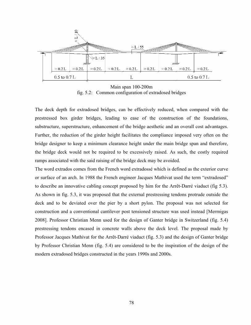
78
Main span 100-200m
fig. 5.2: Common configuration of extradosed bridges
The deck depth for extradosed bridges, can be effectively reduced, when compared with the
prestressed box girder bridges, leading to ease of the construction of the foundations,
substructure, superstructure, enhancement of the bridge aesthetic and an overall cost advantages.
Further, the reduction of the girder height facilitates the compliance imposed very often on the
bridge designer to keep a minimum clearance height under the main bridge span and therefore,
the bridge deck would not be required to be excessively raised. As such, the costly required
ramps associated with the said raising of the bridge deck may be avoided.
The word extrados comes from the French word extradossé which is defined as the exterior curve
or surface of an arch. In 1988 the French engineer Jacques Mathivat used the term “extradosed”
to describe an innovative cabling concept proposed by him for the Arrêt-Darré viaduct (fig 5.3).
As shown in fig. 5.3, it was proposed that the external prestressing tendons protrude outside the
deck and to be deviated over the pier by a short pylon. The proposal was not selected for
construction and a conventional cantilever post tensioned structure was used instead [Mermigas
2008]. Professor Christian Menn used for the design of Ganter bridge in Switzerland (fig. 5.4)
prestressing tendons encased in concrete walls above the deck level. The proposal made by
Professor Jacques Mathivat for the Arrêt-Darré viaduct (fig. 5.3) and the design of Ganter bridge
by Professor Christian Menn (fig. 5.4) are considered to be the inspiration of the design of the
modern extradosed bridges constructed in the years 1990s and 2000s.
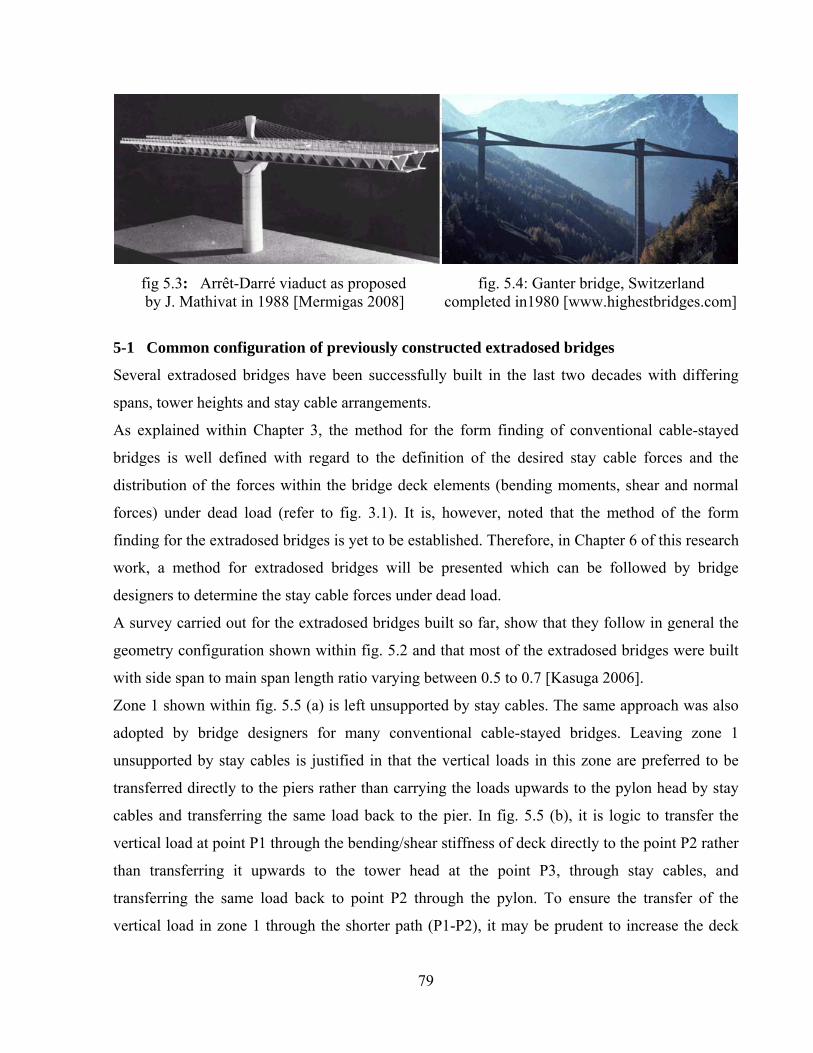
79
fig 5.3: Arrêt-Darré viaduct as proposed fig. 5.4: Ganter bridge, Switzerland by J. Mathivat in 1988 [Mermigas 2008] completed in1980 [www.highestbridges.com]
5-1 Common configuration of previously constructed extradosed bridges
Several extradosed bridges have been successfully built in the last two decades with differing
spans, tower heights and stay cable arrangements.
As explained within Chapter 3, the method for the form finding of conventional cable-stayed
bridges is well defined with regard to the definition of the desired stay cable forces and the
distribution of the forces within the bridge deck elements (bending moments, shear and normal
forces) under dead load (refer to fig. 3.1). It is, however, noted that the method of the form
finding for the extradosed bridges is yet to be established. Therefore, in Chapter 6 of this research
work, a method for extradosed bridges will be presented which can be followed by bridge
designers to determine the stay cable forces under dead load.
A survey carried out for the extradosed bridges built so far, show that they follow in general the
geometry configuration shown within fig. 5.2 and that most of the extradosed bridges were built
with side span to main span length ratio varying between 0.5 to 0.7 [Kasuga 2006].
Zone 1 shown within fig. 5.5 (a) is left unsupported by stay cables. The same approach was also
adopted by bridge designers for many conventional cable-stayed bridges. Leaving zone 1
unsupported by stay cables is justified in that the vertical loads in this zone are preferred to be
transferred directly to the piers rather than carrying the loads upwards to the pylon head by stay
cables and transferring the same load back to the pier. In fig. 5.5 (b), it is logic to transfer the
vertical load at point P1 through the bending/shear stiffness of deck directly to the point P2 rather
than transferring it upwards to the tower head at the point P3, through stay cables, and
transferring the same load back to point P2 through the pylon. To ensure the transfer of the
vertical load in zone 1 through the shorter path (P1-P2), it may be prudent to increase the deck

80
thickness in this zone (by providing deck haunch) as shown within fig. 5.5 (c). Fig. 5.2 shows
also that the extradosed bridges have been built with stay cable angles to the horizontal as low as
15-degress. To ensure the effectiveness of the stay cables, this angle cannot be less than the said
15-degrees. The central part of the main span (zone 3) is not supported by stay cables and,
therefore, the deck transfers the vertical loads in this zone through its bending stiffness to the stay
cables in zones 2. It can also be noted that the common configuration of extradosed bridges does
not have backstays contrary to the cable-stayed bridges (refer to fig. 5.1 and Section 2-2).
fig. 5.5: Cables configuration for extradosed bridges
5-2 Design of stay cables for conventional cable-stayed bridges and extradosed bridges
Similar to the conventional cable-stayed bridges, the stay cable forces for the extradosed bridges
under dead load, can be controlled by shortening the cables to predetermined lengths to achieve
specific desired bending moment distribution. A proposal for the determination of the desired
stay cable forces under dead load for extradosed bridges will be presented in Chapter 6. Upon the
selection of the stay cable forces under dead load, the stay cable forces under live load may be
estimated as a percentage of the stay cable forces under dead load and the size of the stay cables
may be calculated accordingly based on the allowable stresses in the Service Limit State as per
the respective specification. The estimated sizes of the stay cables should then be checked for
compliance with the requirements of the fatigue limit state and the strength limit state. This
process should be repeated (“iteration process”) until an economical design is reached (i.e. until
the minimum size/weight of stay cables is reached).
The compliance with the fatigue limit state will depend mainly on the ratio between the live load
q corresponding to the type of traffic the bridge is subjected, and the dead load w [Walter et al.

81
1999]. If the ratio q/w is small (case of concrete cable-stayed bridges), the axial stress variation
due to live load q in the stay cables will be smaller than the permissible limit of the stress
variation per (guaranteed by the manufacturer of the cable based on tests carried out over two
million cycles) and the load bearing capacity of the selected stay cable cross section will be fully
utilized (refer to fig. 5-6 / Strength criterion):
qperandw + q = a
The load bearing capacity is defined as the multiplication of the allowable axial stress at the
service limit state a times the cross sectional area of the stay cable and a at SLS is taken
normally by several international specifications equal to 0.45 times the ultimate tensile strength
of the stay cable material UTS .
On the other hand, if the ratio q/w is high as it is the case for steel railway bridges for example,
the stress variation due to live load q will be high and the load bearing capacity of the selected
stay cable cross section will not be fully utilized (refer to fig. 5-6/Fatigue criterion):
qperandw + q < a
fig. 5.6: Strength criterion and fatigue criterion for the design of stay cables [Walter et al. 1999]
Further to fig. 5.6, the strength and fatigue criterions may be represented by equations (5.1) and
(5.2) and fig. 5.7 [Walter et al. 1999]:
1 1 1
w a aw q q q
1 x MPa x 1 797 1 MPaw q w w w
- - -æ ö æ ö æ ö÷ ÷ ÷ç ç çs = s = + s = + = +÷ ÷ ÷ç ç ç÷ ÷ ÷ç ç çè ø è ø è ø+
(5.1)
For a stay cable system with a permissible stress variation per equal to say 200 MPa:
1 1
w per perw q q
MPaq w w
- -æ ö æ ö÷ ÷ç çs = Ds = Ds÷ ÷ç ç÷ ÷ç çè ø è ø (5.2)

82
fig. 5.7: Relationship between the dead load permissible stress w and the ratio q/w [Walter et
al. 1999]
From fig. 5.7, it can be understood that the fatigue criterion governs the design of the stay cables
for a ratio of q/w exceeding 0.30 at w ≈ 600 Mpa (Note: this is valid only if per = 200 MPa).
The pylon height for the extradosed bridges built so far are equal to approximately one tenth of
the main span length which is equal to half of the corresponding pylon height for conventional
cable-stayed bridges. The short pylon, the relatively stiff deck and in addition the absence of the
back stays in the case of the extradosed bridges (as compared to the conventional cable-stayed
bridges), limit the variation of the stresses in the stay cables due to live loads. The stress
variations due to live loads, remain generally less than the corresponding stress variations for
conventional cable-stayed bridges. Accordingly the restrictions of limiting the stresses in all stay
cables to 0.45 x the ultimate tensile strength of the stay cable material UTS as required by several
international design codes, may be relaxed.
The SETRA recommendations link the allowable axial stress a at SLS for the stay cables with
the stress variation L due to SLS live loads and can be determined from the following equation
(refer also to fig. 5.8). The allowable axial stress a is applicable for the entire stay cable system
[SETRA 2002] [Mermigas 2008].
UTS L
0.25L
a a UTS L
UTS L
0.6 if Pa
if ΜPa140
0.46 if Pa
-
s Ds £
æ öD s ÷çs = s £ s <Ds £÷ç ÷÷çè ø
s Ds
(5.3)

83
The allowable stress a at SLS as per the Japan Prestressed Concrete Engineering Association’s
Specifications, may be determined from the following equations, noting that these two equations
are applicable for the individual stay cables and not for the entire stay cable system as it is the
case of equation 5.3 (refer also to fig. 5.8) [Ogawa and Kasuga 1998] [Kasuga 2006].
For a strand stay cable system fabricated on site (refer also to 2-1-4)
UTS L
a UTS L
UTS L
0.6 if Pa
if 70 ΜPa
0.4 if Pa
s Ds £
s = Ds s <Ds £
s Ds
(5.4)
and for a stay cable wire system fabricated in the factory (refer also to 2-1-3)
UTS L
a UTS L
UTS L
0.6 if Pa
if ΜPa
0.4 if Pa
s Ds £
s = Ds s <Ds £
s Ds
(5.5)
SETRA Recommendations (2001) Japan Prestressed Concrete Engineering Association’s Specifications [Ogawa and Kasuga 1998] [Kasuga 2006] fig. 5.8: Allowable stresses for stay cables of extradosed bridges versus the stress variation due
to live loads
The SLS design method demonstrated above involves implicitly the fatigue consideration for the
stay cable system. The explicit fatigue limit state design requires the stay cable system to be
tested for two million cycles for specific upper stress limits and specific amplitudes. For cable-
stayed bridges, the upper stress limit is taken usually as 45% UTS . The amplitude is commonly
taken as 160 MPa for strand systems and 200 MPa for wire systems. Upon carrying out the
fatigue test, appropriate safety factors should be taken into account to specify the allowable stress

84
variation. PTI indicates that the allowable stress variation may be taken equal to 69 MPa for the
strand system and 105 MPa for the wire system [PTI 2001]. R. Walter [Walter et al. 1999]
suggests simplified method for the definition of the permissible stress variation per by
establishing the Woehler curve (fig. 5-9) from the available test results then deducing the
allowable stress variation per by using the following equation:
test testper
1 2 3 1.5
Ds DsDs = »
g g g
(5.6)
where:
1 ≈ 1.15 is the assumed basic partial coefficient for steel
2 ≈ 1.15 is the partial coefficient taking into account the effect of grouping (tests carried out on
separated wires or strands or the full size of the stay cable). 2 may be set to 1, if the test is
carried out on the full size of the stay cable
3 ≈ 1.15 is the partial coefficient taking into account the conversion of the test values into
characteristic values (may be reduced if sufficient numbers of test results are available)
[SETRA 2002] indicates that test may be taken equal to the 0 shown in fig. 5.9
fig. 5.9: Typical fatigue curve of a cable stay [SETRA 2002]
Upon the determination of test, the stress variation due to the fatigue load should be calculated
(using a structural computer model) and should be less than (0.520/1.5). For a stay cable
system with 0 = 200MPa for example, the allowable stress variation due to the fatigue load =
(0.52 x 200/1.5) ≈ 70MPa. The fatigue load for road bridges as per the Eurocode EN 1991-2-
2003, for example, is shown in fig. 5.10.
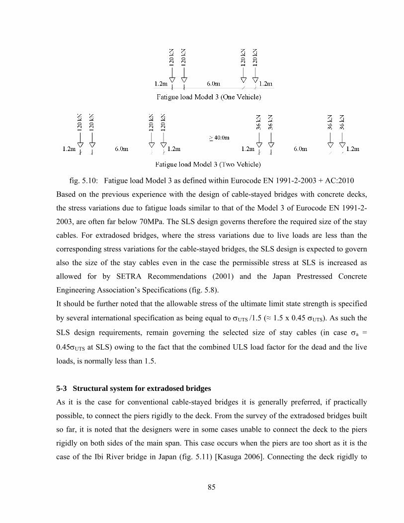
85
fig. 5.10: Fatigue load Model 3 as defined within Eurocode EN 1991-2-2003 + AC:2010
Based on the previous experience with the design of cable-stayed bridges with concrete decks,
the stress variations due to fatigue loads similar to that of the Model 3 of Eurocode EN 1991-2-
2003, are often far below 70MPa. The SLS design governs therefore the required size of the stay
cables. For extradosed bridges, where the stress variations due to live loads are less than the
corresponding stress variations for the cable-stayed bridges, the SLS design is expected to govern
also the size of the stay cables even in the case the permissible stress at SLS is increased as
allowed for by SETRA Recommendations (2001) and the Japan Prestressed Concrete
Engineering Association’s Specifications (fig. 5.8).
It should be further noted that the allowable stress of the ultimate limit state strength is specified
by several international specification as being equal to UTS /1.5 (≈ 1.5 x 0.45 UTS). As such the
SLS design requirements, remain governing the selected size of stay cables (in case a =
0.45UTS at SLS) owing to the fact that the combined ULS load factor for the dead and the live
loads, is normally less than 1.5.
5-3 Structural system for extradosed bridges
As it is the case for conventional cable-stayed bridges it is generally preferred, if practically
possible, to connect the piers rigidly to the deck. From the survey of the extradosed bridges built
so far, it is noted that the designers were in some cases unable to connect the deck to the piers
rigidly on both sides of the main span. This case occurs when the piers are too short as it is the
case of the Ibi River bridge in Japan (fig. 5.11) [Kasuga 2006]. Connecting the deck rigidly to
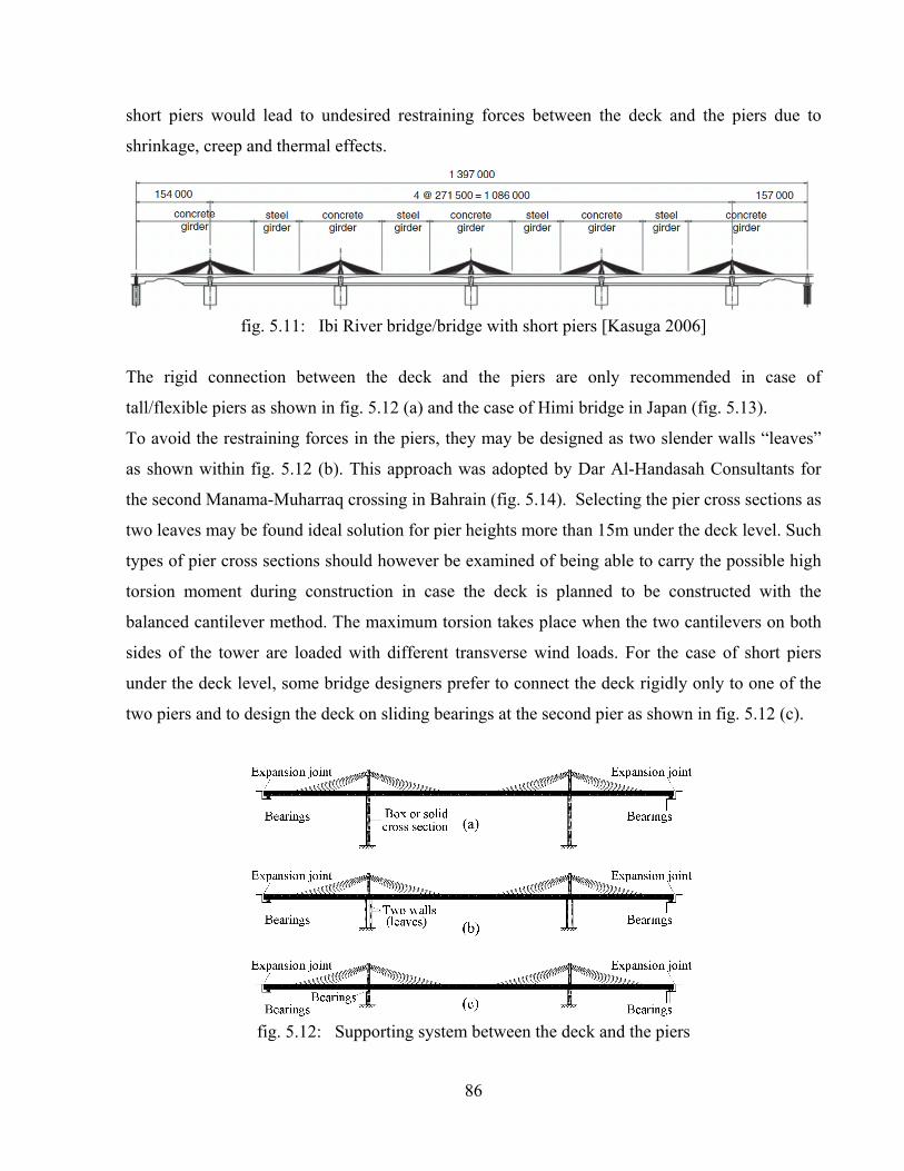
86
short piers would lead to undesired restraining forces between the deck and the piers due to
shrinkage, creep and thermal effects.
fig. 5.11: Ibi River bridge/bridge with short piers [Kasuga 2006]
The rigid connection between the deck and the piers are only recommended in case of
tall/flexible piers as shown in fig. 5.12 (a) and the case of Himi bridge in Japan (fig. 5.13).
To avoid the restraining forces in the piers, they may be designed as two slender walls “leaves”
as shown within fig. 5.12 (b). This approach was adopted by Dar Al-Handasah Consultants for
the second Manama-Muharraq crossing in Bahrain (fig. 5.14). Selecting the pier cross sections as
two leaves may be found ideal solution for pier heights more than 15m under the deck level. Such
types of pier cross sections should however be examined of being able to carry the possible high
torsion moment during construction in case the deck is planned to be constructed with the
balanced cantilever method. The maximum torsion takes place when the two cantilevers on both
sides of the tower are loaded with different transverse wind loads. For the case of short piers
under the deck level, some bridge designers prefer to connect the deck rigidly only to one of the
two piers and to design the deck on sliding bearings at the second pier as shown in fig. 5.12 (c).
fig. 5.12: Supporting system between the deck and the piers
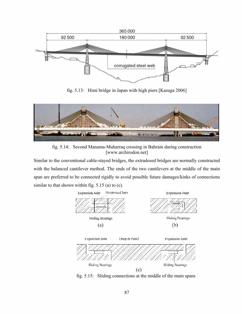
87
fig. 5.13: Himi bridge in Japan with high piers [Kasuga 2006]
fig. 5.14: Second Manama-Muharraq crossing in Bahrain during construction [www.archirodon.net]
Similar to the conventional cable-stayed bridges, the extradosed bridges are normally constructed
with the balanced cantilever method. The ends of the two cantilevers at the middle of the main
span are preferred to be connected rigidly to avoid possible future damages/kinks of connections
similar to that shown within fig. 5.15 (a) to (c).
fig. 5.15: Sliding connections at the middle of the main spans

88
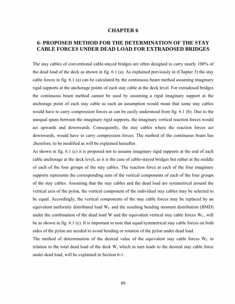
89
CHAPTER 6
6- PROPOSED METHOD FOR THE DETERMINATION OF THE STAY CABLE FORCES UNDER DEAD LOAD FOR EXTRADOSED BRIDGES
The stay cables of conventional cable-stayed bridges are often designed to carry nearly 100% of
the dead load of the deck as shown in fig. 6.1 (a). As explained previously in (Chapter 3) the stay
cable forces in fig. 6.1 (a) can be calculated by the continuous beam method assuming imaginary
rigid supports at the anchorage points of each stay cable at the deck level. For extradosed bridges
the continuous beam method cannot be used by assuming a rigid imaginary support at the
anchorage point of each stay cable as such an assumption would mean that some stay cables
would have to carry compression forces as can be easily understood from fig. 6.1 (b). Due to the
unequal spans between the imaginary rigid supports, the imaginary vertical reaction forces would
act upwards and downwards. Consequently, the stay cables where the reaction forces act
downwards, would have to carry compression forces. The method of the continuous beam has
,therefore, to be modified as will be explained hereafter.
As shown in fig. 6.1 (c) it is proposed not to assume imaginary rigid supports at the end of each
cable anchorage at the deck level, as it is the case of cable-stayed bridges but rather at the middle
of each of the four groups of the stay cables. The reaction force at each of the four imaginary
supports represents the corresponding sum of the vertical components of each of the four groups
of the stay cables. Assuming that the stay cables and the dead load are symmetrical around the
vertical axis of the pylon, the vertical component of the individual stay cables may be selected to
be equal. Accordingly, the vertical components of the stay cable forces may be replaced by an
equivalent uniformly distributed load WC and the resulting bending moment distribution (BMD)
under the combination of the dead load W and the equivalent vertical stay cable forces WC, will
be as shown in fig. 6.1 (c). It is important to note that equal/symmetrical stay cable forces on both
sides of the pylon are needed to avoid bending or rotation of the pylon under dead load.
The method of determination of the desired value of the equivalent stay cable forces WC in
relation to the total dead load of the deck W, which in turn leads to the desired stay cable force
under dead load, will be explained in Section 6-1.

90
fig. 6.1: The BMD for cable-stayed bridges along the deck elements under dead load in comparison with the proposed BMD of an extradosed bridge
6-1 Method of the calculation of the desired equivalent vertical stay cable forces WC
The general configuration of an extradosed bridge with a deck of variable depth under the
variable dead load W(x) and the equivalent vertical stay cable forces WC is shown in fig. 6.2 (a)
In this research work it is proposed to select the equivalent vertical components of the stay cable
forces WC in such a way that the deflection of the deck at the points s1, m1, m3 and s2 are equal to
zero (this means that the deck under dead load will behave as a continuous beam on 8-supports at
the points s1, m1,m3 and s2, in addition to the already existing rigid supports at points 1 to 4. The

91
benefit for this is that for the pertinent moment distribution shown in fig. 6.1 (c) , the effect of
creep due to bending will be eliminated at the points s1, m1, m3 and s2.
Accordingly, using the virtual work method, the following two equations may be written for the
structure shown in fig. 6.2 (b):
(1 ) x Ls1
s1
x L
M(x) M (x)Z dx 0
E I(x)
+h
-h
D = =ò
(6.1)
(6.2)
where:
x = x-coordinate measured from support no. 2
M(x) = the bending moment at any point, along the entire length of the deck, due to the
combination of W(x) and WC
Zs1 = the vertical deflection of deck at s1 due to the combination of W(x) and WC
Zm1 = the vertical deflection of deck at m1 due to the combination of W(x) and WC
Ms1(x) = the bending moment at any point, along the entire length of the deck, due to a vertical
unit load F=1 acting at s1
Mm1(x) = the bending moment at any point, along the entire length of the deck, due to a vertical
unit load F=1 acting at m1
I(x) = the moment of inertia of the deck cross section at any point along the entire length of
the deck
the ratio between the side span and the main span length
For a bridge with a given main span length L, dead load W(x) and moment of inertia of its deck
cross section I(x), the bending moments M(x), Ms1(x) and Mm1(x) along the entire length of the
deck will be dependant only on the unknown parameters WC and Therefore, each of the two
equations (6.1) and (6.2) will have only the two unknowns WC and Accordingly, the solution
of the two equations (6.1) and (6.2) will deliver the values of the two unknowns WC and which
are necessary to obtain a bending moment distribution as if there were rigid supports at the points
s1, m1, m3 and s2. In case such bending moment distribution is achieved, the effect of creep due to
the time dependent effect “type I” at the points s1, m1, m3 and s2, can be eliminated.
(1 ) x Lm1
m1
x L
M(x) M (x)Z dx 0
E I(x)
+h
-h
D = =ò

92
For ease of understanding the method described above for the determination of WC and the
dead load and the moment of inertia of the deck cross section will be considered hereafter to be
constant along the entire length of the deck and they will be assumed to be equal to W and I
respectively. Accordingly the equations (6.3), (6.4) and (6.5) for M(x), Ms1(x) and Mm1(x) can be
written. From fig. 6.2(b), it can be understood that equation (6.3) for the bending moment M(x)
shown in fig. 6.2(d) is required to be written for 11-zones. Similarly, each of the equations (6.4)
and (6.5) is written for 4-zones [refer to figs 6.2(e) and 6.2(f)]. By substituting from equations
(6.3), (6.4) and (6.5) in equations (6.1) and (6.2), equations (6.1) and (6.2) can be solved for WC
and either graphically or numerically using a mathematical software for engineering
calculations [Maxfield, 2006]. Fig. 6.3 shows the graphical solution of equations (6.1) and (6.2).
Each point on the curve representing equation (6.1), provides two values of and WC leading to
a vertical deflection Zs1 at node s1 equal to zero independent of the vertical deflection Zm1 at
point m1. Similarly, each point on the curve representing equation 6.2, provides two values of
and WC leading to a vertical deflection Zm1 at node m1 equal to zero independent of the vertical
deflection Zs1 at point s1. Accordingly, the intersection point of the two curves representing
equations (6.1) and (6.2), is the point at which the two values and WC lead to simultaneous
vertical deflection at the points s1 and m1 equal to zero. Due to the structure/loads symmetry, the
deflection at the points m3 and s2 will be also equal to zero. It can, therefore, be concluded from
fig. 6.3 that the vertical deflection at the points s1, m1, m3 and s2 (for the case of constant dead
load W and constant moment of inertia I) may be achieved in case the equivalent vertical
component of the stay cable forces WC is approximately equal to 1.9 W and the side span to the
main span ratio is equal to 0.615. Accordingly, the bending moment distribution shown in fig
6.2(b) will take the desired diagram shown in fig. 6.2 (g).
Based on the above described approach, it can be also concluded that the stay cables will carry
approximately 70 % of the dead load:
C4 W x (0.2 L) 4 x 1.9 W x 0.2 L70%
W (2 L L) W ( 2 x 0.615 L L)= »
h + +
As expected, the contribution of the stay cables for carrying the dead load of extradosed bridges
is less than the corresponding contribution of the stay cables in case of conventional cable-stayed
bridges which reaches nearly 100% [refer to fig. 6.1 (a)].

93
fig. 6. 2: Method for the calculation of the desired equivalent stay cable forces WC

94
From fig. 6.2(b), M(x) in fig. 6.2(d) may be written for 11-zones as follows:
( )
( ) ( )
2
1
2 2
1 C
1
L xR ( L x) W if L x 0.4 L
2
L x 0.4 L xR ( L x) W W if 0.4 L x 0.2 L
2 2
R ( L x) W
M(x)
h +h + - -h £ £
h + +h + - - < £
hh + -
=
( )
( )
2
C
2
2 2r
22
2 2r C
L x0.2 L W (0.3 L x) if 0.2 L x 0
2
xM W Q x if 0 x 0.2 L
2
x 0.2 LxM W Q x W
2 2
++ - < £
- - < £
-- - +
( )
( )( )
2
2 2r C
22
2 2r C C
if 0.2 L x 0.4 L
xM W Q x 0.2 L W x 0.3 L if 0.4 L x 0.6 L
2
x 0.6 LxM W Q x 0.2 L W x 0.3 L W if 0.6 L
2 2
< £
- - + - < £
-- - + - <
( )
( )
( )
2
2 2r C
2
3 3r
2
3 3r
x 0.8L
xM W Q x 0.4 L W x 0.5 L if 0.8 L x L
2
x LM W Q x L) if L x L
2
x LM W Q
2
£
- - + - < £
-- - - < £
-- -
( )
( )( ) (
2
C
2
3 3r C
x 1.2 Lx L) W if L x L
2
x LM W Q x L) L W x 1.3 L if L x 1
2
-- < £
-- - - - < £ + h
From fig. 6.2(e), Ms1(x) may be written for 4-zones as follows:
(6.3)
( )( )
1s1
1s1s1
Q2s1 2rs1
Q3s1 3rs1
R L x if L x 0.3 L
R L x ( 0.3 L + x) if 3 L x 0M (x)
M x if 0 x 0.3 L
M x L)
-
-
h + -h £ £
h + - < £=
< £
-
( )if L x 1 L< £ + h
(6.4)
From fig. 6.2(f), Mm1(x) may be written for 4-zones as follows:
( )1m1
Q2m1 2rm1m1
Q2m1 2rm1
Q3m1 3rm1
R L x if L x 0
M x if 0 x 0.3 LM (x)
M x (x 0.3 L) if 0.3 L x L
M x L)
-
-
-
h + -h £ £
< £=
+ - < £
-
( )if L x 1 x L< £ + h
(6.5)
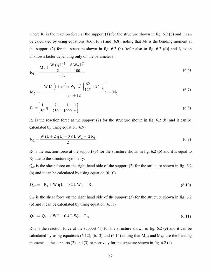
95
where R1 is the reaction force at the support (1) for the structure shown in fig. 6.2 (b) and it can
be calculated by using equations (6.6), (6.7) and (6.8), noting that M2 is the bending moment at
the support (2) for the structure shown in fig. 6.2 (b) [refer also to fig. 6.2 (d)] and f is an
unknown factor depending only on the parameter .
22C
2
1
6 W LW ( L)M
2 100RL
h+ -
=h
(6.6)
( )2 3 2C
2 3
62W L 1 W L 24 f
125M M
8 12
hæ ö÷ç- + h + ÷ç ÷çè ø
= =h +
(6.7)
1 7 1 1f
50 750 1000hæ ö÷ç= h - + ÷ç ÷ç ÷ç hè ø
(6.8)
R2 is the reaction force at the support (2) for the structure shown in fig. 6.2 (b) and it can be
calculated by using equation (6.9)
C 12
W (L 2 L) L W 2 RR
2
+ h -=
(6.9)
R3 is the reaction force at the support (3) for the structure shown in fig. 6.2 (b) and it is equal to
R2 due to the structure symmetry.
Q2r is the shear force on the right hand side of the support (2) for the structure shown in fig. 6.2
(b) and it can be calculated by using equation (6.10)
2r 1 C 2Q R W L 0.2 L W R= - + h - - (6.10)
Q3r is the shear force on the right hand side of the support (3) for the structure shown in fig. 6.2
(b) and it can be calculated by using equation (6.11)
3r 2r C 3Q Q W L L W R= + - - (6.11)
R1s1 is the reaction force at the support (1) for the structure shown in fig. 6.2 (e) and it can be
calculated by using equations (6.12), (6.13) and (6.14) noting that M2s1 and M3s1 are the bending
moments at the supports (2) and (3) respectively for the structure shown in fig. 6.2 (e).

96
2s11s1
M 0.3 LR
L
-=
h
(6.12)
( )2s1 3s1M 2 1 M=- h + (6.13)
( )2
3s1 2
L6 0.1 0.045 0.0045
M1 4 (
h - h +h
=- h +
(6.14)
R4s1 , R3s1 , R2s1 are the reaction forces at the support (4), (3) and (2) for the structure shown in
fig. 6.2 (e) and they can be calculated by using equations (6.15), (6.16) and (6.17)
3s14s1
MR
L=
h (6.15)
( )2s1 4s13s1
M R 1 LR
L
- h +=
(6.16)
( )3s1 1s12s1
M R 1 L 1.3 LR
L
- h + -=
(6.17)
Q2rs1 is the shear force on the right hand side of the support (2) for the structure shown in fig. 6.2
(e) and it can be calculated by using equation (6.18)
2rs1 1s1 2s1Q R R 1= - - - (6.18)
Q3rs1 is the shear force on the right hand side of the support (3) for the structure shown in fig. 6.2
(e) and it can be calculated by using equation (6.19)
3rs1 1s1 2s1 3s1Q R R 1 R= - - - - (6.19)
R1m1 is the reaction force at the support (1) for the structure shown in fig. 6.2 (f) and it can be
calculated by using equations (6.20), (6.21) and (6.22) noting that M2m1 and M3m1 are the bending
moments at the supports (2) and (3) respectively for the structure shown in fig. 6.2 (f).

97
2m11m1
MR
L=
h (6.20)
( )( )
2m1 2
0.714 1 0.273M x L
4 1
h + -=
h +
(6.21)
( )3m1 2m1M 0.357 L 1 M= - h + (6.22)
R4m1 , R3m1 and R2m1 are the reaction forces at the support (4), (3) and (2) for the structure shown
in fig. 6.2 (f) and they can be calculated by using equations (6.23), (6.24) and (6.25)
3m14m1
MR
L=
h (6.23)
( )3m1 1m12m1
M R 1 L 0.7 LR
L
- h + -=
(6.24)
( )2m1 4m13m1
M R 1 L 0.3 LR
L
- h + -=
(6.25)
Q2rm1 is the shear force on the right hand side of the support (2) for the structure shown in fig. 6.2
(f) and it can be calculated by using equation (6.26)
2m1 1m1 2m1Q R R=- - (6.26)
Q3rm1 is the shear force on the right hand side of the support (3) for the structure shown in fig. 6.2
(f) and it can be calculated by using equation (6.27)
3m1 1m1 2m1 3m1Q R R 1 R=- - - - (6.27)

98
fig. 6.3: Determination of the ideal values of and WC / W
Upon the determination of the desired equivalent stay cable forces WC and the corresponding
desired bending moment distribution as explained above, the desired stay cable force for each
stay cable FDi under dead load may be determined, by hand calculatin, by using the following
equation (refer also to fig. 6.4):
CDi
i i
W L WLF
n ' sin ( ) n ' sin ( )=
q q
(6.28)
where:
n’ = the nos. of the stay cables within the length 0.2 L
i = the angle of stay cable i as shown in fig. 6.4 (a)
For the achievement of the desired stay cable forces FDi under dead load in the computer model,
during the design stage, each stay cable will be required to be shortened/re-stressed by a force
equal to Fi . The re-stressing force Fi for each stay cable may be determined by using equation
(29) (refer to Section 3-3). For the installation of the stay cables during construction, the un-
stressed length for stay cable no. i, should be determined from the force FDi and the stressed
length Li calculated from the deformed bridge structure shown in fig. 6.4 (c). In case the deck
elements are fabricated with a precamber profile [= the mirror profile of the deck deflection line
shown in fig. 6.4 (c)], the un-stressed length of the stay cable no. i, is to be determined by using
the force FDi and the stressed length Li calculated from the un-deformed structure.

99
( )
( )
( )
( ) ( ) ( ) ( )( ) ( )
( )
11 12 1i 1n1 n 1
21 22 2i 2n2 n 1
j1 j2 ji jnj n 1
n 1 1 n 1 2 n 1 i n 1 n 1 n 1 n
n1 n2 nj nnn n 1
f f ... f ... f f
f f ... f ... f f
... ... ... ... ... ... ...
f f ... f ... f f
... ... ... ... ... ... ...
f f ... f ... f f
f f ... f ... f f
-
-
-
- - - - - -
-
æ ö÷ç ÷ç ÷ççççççççççççççççççççççççè ø
( ) ( )
1 D1 1
2 D2 2
j Dj j
(n 1)n 1 D n 1
n Dn n
F F F
F F F
... ...
F F F
... ...
F F F
F F F
-- -
æ ö æ öD -÷ ÷ç ç÷ ÷ç ç÷ ÷ ÷÷ ç ç÷ ÷D -÷ ç ç÷ ÷÷ ç ç÷ ÷÷ ç ç÷ ÷÷ ÷ ÷ç ç÷ ÷ ÷ç ç÷ ÷ ÷ç ç÷ ÷ ÷ç ç÷ ÷ ÷÷ D -ç ç÷ ÷=÷ ç ç÷ ÷÷ ç ç÷ ÷÷ ç ç÷ ÷÷ ÷ ÷ç ç÷ ÷ ÷ç ç÷ ÷ç ç÷ ÷÷ ç ç÷D -÷ ç ç÷÷ ç ç÷÷ ç ç÷÷ ÷ç ç÷ ÷ç çD -÷ è ø è ø÷
÷÷÷÷÷÷÷÷
(6.29)
where (refer also to fig. 6.4) : n = total nos. of stay cables
FDi = desired stay cable force for the cable no. i as per equation (6.28)
Fi = stay cable force of the cable no. i under the effect of the dead load prior to the shortening/re-stressing of any stay cable by the forces Fi
Fji = force in stay cable no. j due to tensioning the stay cable no. i by a force equal to 1 Note: Upon the re-stressing of all stay cables by the respective force Fi, the stay cable force Fi and the bending moment distribution shown in fig. 6.4 (a) will be changed to the desired stay cable force FDi and the desired bending moment distribution shown in fig. 6.4(b).
fig. 6.4: Method for the calculation of the desired stay cable force FDi as per equation (6.29)

100
6-2 Proposed method for handling the prestressing forces for extradosed bridges
As explained under Section 6-1, equation (6.29) can be used to achieve the bending moment
distribution shown in fig. 6.4(b). Equation (6.29) is suitable for use for extradosed bridges with
steel deck or steel/concrete composite deck. For extradosed bridges with concrete deck section,
the bending moment distribution shown in fig.6.4(b), can be further reduced by using prestressing
tendons as will be explained. The use of prestressing tendons for extradosed bridges is helpful
during erection and also for the completed structure, noting that the stay cables do not support the
entire deck length contrary to the configuration of conventional cable-stayed bridge.
6-2-1 Use of concordant prestressing cable profiles for continuous beams [Lin and Burns 1989] [Leonhardt 2004]
To ease the understanding of the possible use of concordant prestressing profiles within the deck
of extradosed bridges, such prestressing arrangement will be first briefly explained for continuous
beams resting on rigid and flexible supports. Fig. 6.5 (a) shows a continuous beam on rigid
supports under the effect of uniform load W and the related reaction forces Ri. The typical
bending moment distribution resulting from W is shown in fig. 6.5 (b). The prestressing tendons
which may be used for such a continuous beam can be grouped and represented by a cable profile
affine with the bending moment distribution shown in fig. 6.5 (b). This means that the ordinate of
the cable profile at any point z(x), measured from the neutral axis of the continuous beam, will be
equal to M(x) divided by a constant value C (=the affinity factor) [refer to fig. 6.5 (c) ].
M(x)z(x)
C= (6.30)
Assuming that the prestressing force of the concordant cable is equal to FP and by ignoring the
friction prestressing losses, the prestressing forces of the concordant cable may be replaced by an
equivalent uniform load Weq and equivalent nodal loads Peq-i acting at the support no. i.
where:
2 2P P
eq P 2 2
F Fd z(x) d M(x)W F W
C Cdx dx= = = (6.31)
Peq i i
FP R
C- = (6.32)

101
From equations (6.31) and (6.32), it can be seen that the ratio between the equivalent uniform
load Weq and W is equal to the ratio between the equivalent nodal load Peq-i and the reaction force
Ri. Accordingly, the vertical reaction forces R’i at the rigid supports due to the concordant
prestressing forces will be equal to zero [refer to fig. 6.5 (d)] regardless of the selected
prestressing force FP. It can be further understood that in case the prestressing force FP is selected
to be equal to the affinity factor C in equation (6.30), the equivalent uniform and nodal loads Weq
and Peq-i will be equal to W and Ri respectively. Accordingly, the resultant bending moment due
to the combination of the external load W and the prestressing forces will be equal to zero.
fig. 6.5: Use of a concordant prestressing cable profile for continuous beams
As the deck of the extradosed bridges is carried by rigid supports (piers and abutments) and
elastic supports (stay cables), the use of the concordant prestressing for continuous beams resting
on flexible supports will be also explained. Fig. 6.6 shows the application of the concordant cable
profile on a continuous beam resting on internal flexible springs in addition to the end rigid
supports. The reaction forces of the internal springs Si due to the external uniform load W, are
shown in fig. 6.6 (a). The reaction forces of the springs and the corresponding bending moment
distribution M(x) shown in fig. 6.6 (b) will be dependent on both of the stiffness of the springs

102
and the bending stiffness of the beam. In case the used prestressing tendons are represented by a
concordant cable profile fig. 6.6 (c), the ordinate z(x) of such a cable profile will be equal to the
value of M(x) shown in fig. 6.6 (b) divided by the affinity factor C (refer to equation 6.30).
Assuming further that the prestressing force FP, is selected equal to C, the prestressing forces can
be replaced by the equivalent uniform and nodal loads Weq and Peq-i as shown in fig. 6.6 (d). The
values of the equivalent loads Weq and Peq-i will be equal to W and Si shown in fig. 6.6 (a) but in
opposite direction. By comparing figs. 6.6 (d) and 6.6 (a), the reaction forces at the springs due to
the upward equivalent uniform load Weq (= W) alone, will be equal to downward reaction forces
Si having the same values shown in fig. 6.6 (a). As the upward reaction forces due to the
equivalent nodal loads Peq-i shown in fig. 6.6 (d), would be equal to Si only in case the springs are
very stiff, the final reaction forces R’i of the internal springs will not be equal to zero as it would
have been in the case of internal rigid supports. Accordingly, the resultant bending moment due
to the combination of the external load W and the concordant prestressing forces, will not be
equal to zero.
fig. 6.6: Behavior of continuous beam on springs under the effect of the equivalent prestressing
forces

103
6-2-2 Possible use of concordant cable profiles for the extradosed bridges
The typical prestressing configuration for extradosed bridges follows in general the arrangement
shown in fig. 6.7 (a). Similar prestressing configuration was adopted for the design of Odawara
extradosed bridge in Japan (completed in 1994) and the Second Vivekananda extradosed bridge
in India (completed in 2007). As explained under 6.1, it is possible to select the stay cable forces
for the completed bridge to achieve bending moment distribution under dead load similar to that
shown in fig. 6.4 (b). The achievement of such bending moment distribution allows the possible
use of draped tendons within the side and main spans of extradosed bridges. A study has been
made to investigate the possible arrangement of concordant cable profile as that shown in fig.
6.7(b) which is affine with the bending moment distribution of fig. 6.4 (b). As explained under
6.2.1, the use of concordant prestressing profile within a continuous beam on flexible supports,
does not lead to zero reaction forces at the flexible supports. Similarly, the use of concordant
cable profiles within the deck elements of the extradosed bridge [(fig. 6.7 (b)] leads to a change
of the stay cable forces. Fig. 6.8 (a) shows the bending moment distribution for extradosed bridge
under dead load before re-stressing the stay cables [which is similar to fig. 6.4 (a)]. Under the
effect of the concordant prestressing alone, the change of the force in stay cable “i” is assumed
to be equal to FPTi [ refer to fig. 6.8 (b) ]. Due to the existence of the stay cable forces FPTi ,
resulting from the prestressing forces, the bending moment distribution shown in fig. 6.8 (b) is
not exactly equal to the mirror of the bending moment distributions shown in fig 6.8 (c) or 6.4
(b) which are based on the calculation made under 6.1. If however, each stay cable force is re-
stressed by a force Fi in accordance with equation 6.33 (compare it with equation 6.29), the
desired stay cable forces FDi (as calculated under 6.1) will be kept unchanged and the final
bending moment distribution due to dead load, stay cable forces and prestressing forces will be
equal to zero.
( )
( )
( )
( ) ( ) ( ) ( )( ) ( )
( )
11 12 1i 1n1 n 1
21 22 2i 2n2 n 1
j1 j2 ji jnj n 1
n 1 1 n 1 2 n 1 i n 1 n 1 n 1 n
n1 n2 nj nnn n 1
f f ... f ... f f
f f ... f ... f f
... ... ... ... ... ... ...
f f ... f ... f f
... ... ... ... ... ... ...
f f ... f ... f f
f f ... f ... f f
-
-
-
- - - - - -
-
æ ö÷ç ÷ç ÷ççççççççççççççççççççççççè ø
( ) ( )
D1 1 PT11
D2 2 PT22
Dj j PTjj
(n 1) PTD n 1n 1 (n 1)
n Dn n PTn
F F FF
F F FF
......
F F FF
......
F F FF
F F F F
--- -
ææ ö - -D ÷ çç ÷ çç÷ ÷ ç÷ ç ÷ - -D÷ çç ÷÷ çç ÷÷ çç ÷÷ ç÷ç÷ ÷ çç÷ ÷ çç÷ ÷ çç÷ ÷ - -÷ D çç ÷ =÷ çç ÷÷ çç ÷÷ çç ÷÷ ÷ç÷ ÷ç÷ ÷ç÷ ÷÷ ç ÷ - -D÷ ç ÷÷ ç ÷÷ ç ÷÷ ÷ç÷ ÷ç D - -÷ è ø è÷
ö÷÷÷÷÷÷÷÷÷÷÷÷÷÷÷÷÷ç ÷ç ÷ç ÷ç ÷ç ÷ç ÷ç ÷÷ç ÷ç ø
(6.33)
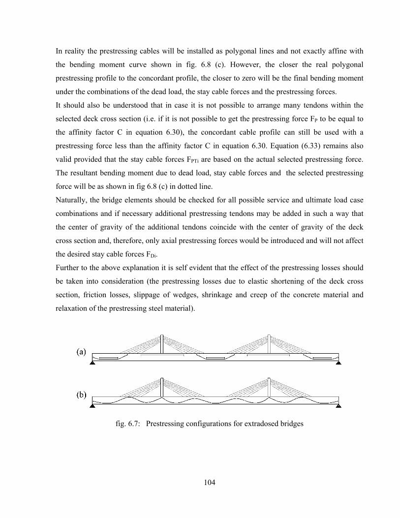
104
In reality the prestressing cables will be installed as polygonal lines and not exactly affine with
the bending moment curve shown in fig. 6.8 (c). However, the closer the real polygonal
prestressing profile to the concordant profile, the closer to zero will be the final bending moment
under the combinations of the dead load, the stay cable forces and the prestressing forces.
It should also be understood that in case it is not possible to arrange many tendons within the
selected deck cross section (i.e. if it is not possible to get the prestressing force FP to be equal to
the affinity factor C in equation 6.30), the concordant cable profile can still be used with a
prestressing force less than the affinity factor C in equation 6.30. Equation (6.33) remains also
valid provided that the stay cable forces FPTi are based on the actual selected prestressing force.
The resultant bending moment due to dead load, stay cable forces and the selected prestressing
force will be as shown in fig 6.8 (c) in dotted line.
Naturally, the bridge elements should be checked for all possible service and ultimate load case
combinations and if necessary additional prestressing tendons may be added in such a way that
the center of gravity of the additional tendons coincide with the center of gravity of the deck
cross section and, therefore, only axial prestressing forces would be introduced and will not affect
the desired stay cable forces FDi.
Further to the above explanation it is self evident that the effect of the prestressing losses should
be taken into consideration (the prestressing losses due to elastic shortening of the deck cross
section, friction losses, slippage of wedges, shrinkage and creep of the concrete material and
relaxation of the prestressing steel material).
fig. 6.7: Prestressing configurations for extradosed bridges

105
fig. 6.8: Method for the calculation of the desired stay cable force FDi taking into account the effect of the prestressing forces as per equation (6.33)
6-2-3 Handling prestressing configurations other than concordant profiles
The advantage of the possible use of concordant cable profile within the deck elements of the
extradosed bridges is explained under 6.2.2. Bridge designers may, however, opt to use external
straight tendons as that shown in figs. 6.9 to 6.11, noting that the external tendons have the
advantage of being replaceable. In case the deck is to be constructed with the balanced cantilever
method, the use of permanent top straight tendons similar to that shown in fig. 6.10, may be
found as the preferred option rather than using temporary stressing bars.
Such arrangement of prestressing cables (internal or external) may affect the desired stay cable
forces FDi calculated under 6.1 by up to nearly 15%. The use of equation (6.33) may however
serve to handle both of the stay cable forces and the prestressing forces separately as far as the

106
bending moment distributions due to both of them are concerned. By using equation (6.33), the
change of the stay cable forces due to any selected prestressing configuration can be eliminated.
Accordingly, the bending moment distribution resulting from any selected scheme of the
prestressing can be determined as if the stay cables were not existing. Based on this approach the
bending moments resulting from the prestressing configurations shown in figs. 6.9 to 6.13, may
be calculated with the help of equations (6.34) to (6.60) noting that these equations were derived
assuming that the moment of inertia of the deck cross section is constant along the entire bridge
length and noting also that the prestressing losses have been ignored (Note: the reaction forces at
the supports nos. 1 and 2 and the bending moment at the support no. 2 are sufficient to draw the
bending moment diagram BMD along the entire deck length). These equations are considered to
be very useful during the initial design stage where simple hand calculations are normally
preferred to be carried out. Using the same equations, the plausibility of the computer results
during the detailed design stage may be examined as well.
In fig. 6.12, it is useful to understand that the function of the draped tendons as per the equations
6.43 to 6.49 along with equation 6.33, is to counterbalance part or the full uniform dead load W
from the central span, where there are no stay cables, without affecting the stay cable forces. The
extent of the said counterbalancing of the uniform dead load W, will depend on the selected nos.
of prestressing tendons and/or the prestressing force FP. The same is valid for the draped tendons
in the side spans shown in fig. 6.13 (refer also to equations 6.50 to 6.60.
The forces resulting from the bottom straight tendons at the middle of the main span (fig. 6-9):
f P bM F e = (6.34)
f2 f
L 1M 3 M
L 3 2
= -
+ h (6.35)
2 f1f 2f f 2
M L 1R R 3 M
L 3 2L
= =
h + hh (6.36)
The forces resulting from the top straight tendons at the pylons (fig. 6-10)
s P tM F e= (6.37)
2s s
2 s 2 2 2
24 L L 3 LM M 1
12 L 1) 4 L
æ öh - ÷ç ÷ç= ÷ç ÷ç ÷h h + - hè ø
(6.38)
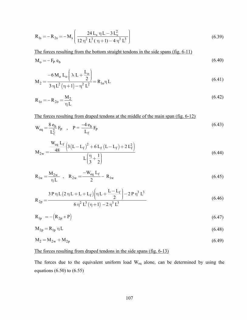
107
2s s
1s 2s s 2 3 3 3
24 L L 3 LR R M
12 L 1) 4 L
æ öh - ÷ç ÷ç= = ÷ç ÷÷ç h h + - hè ø (6.39)
The forces resulting from the bottom straight tendons in the side spans (fig. 6-11)
o P bM F e = (6.40)
( )
oo o
2 1o2 2 2
L6 M L L
2R L
3 L 1 L
æ ö÷ç- l + ÷ç ÷çè ø= = h
h h + - h (6.41)
21o 2o
MR R
L
= =
h
(6.42)
The forces resulting from draped tendons at the middle of the main span (fig. 6-12)
b beq P P2
ff
e eW F , P = F
LL
=
(6.43)
( ) ( )( )2eq f 2f f f f
2w
W L3 L L 6 L L L 2 L
48M1
L3 2
- + - +=
æ öh ÷ç + ÷ç ÷çè ø
(6.44)
eq f2w1w 2w 1w
W LMR R R
L 2
-= =
h (6.45)
( )
( )
3 3ff
2p 2 3 3 3
L L3 P L 2 L L L L 2 P L
2R
6 L 1 L
æ ö- ÷çh h + + h + - h÷ç ÷çè ø=
h h + h
(6.46)
( )1p 2pR R P =- (6.47)
2p 1pM R L= h (6.48)
2 2w 2pM M M = + (6.49)
The forces resulting from draped tendons in the side spans (fig. 6-13) The forces due to the equivalent uniform load Weq alone, can be determined by using the
equations (6.50) to (6.55)

108
beq P2
o
eW F
L=
(6.50)
o o
1 eq o 2 eq o
L LL L L
2 2r W L , r W L
L L
æ ö æ ö÷ ÷ç çh - l - l ÷ ÷ç ç÷ ÷ç çè ø è ø= =
h h
(6.51)
where r1 and r2 are supplementary variables and will be used below to determine M2w in equation (6.52)
( ) ( )( )
( )( )
oo3
21 o 2 o o 1 2 o
oo
3 2eq o 2 o 2w
LLLL1 1 32L r L r L L L L r L r L L L
3 L 2 L
L 2L L L LL1 1 132W L r L L L M L
12 L 2 L 2 3
l l l + h - l - l - h - l -
h h h
h - h - l -l æ öh ÷ç+ + h - l - = +ççè øh h
÷÷
(6.52)
The forces due to each two symmetrical nodal loads P, may be calculated by using equations
(6.55) to (6.60). Lsi in equation (6.56) should be substituted by (L - L - Lo) and (L - L) for
the first and the second two symmetrical nodal loads respectively as per equation (6.57) The
final forces resulting from the equivalent uniform loads Weq and the 2x2 vertical nodal loads P,
can be determined then by superposition.
bP
f
eP = F
L
(6.55)
( )( ) ( ) ( ) ( )( )( )
2 22 si si si si si si
2p 2 3 3 3i 1
P 3 L L L L L L L L L L 3 L L LR
3 L 1 L
=
- h h + + h - - h - h - h -
h + -å (6.56)
s1 o s2L L - L - L L L - L = l = l (6.57)
1p 2pR P R = - (6.58)
( )2p 1p s1 s2M R L P L L = h + + (6.59)
2 2w 2pM M M = + (6.60)
oeq o 2w
1w
LW L L L M
2R
L
æ ö÷çh - l - -÷ç ÷çè ø= -
h
(6.53)
( )2w eq o 1wR W L R =- (6.54)
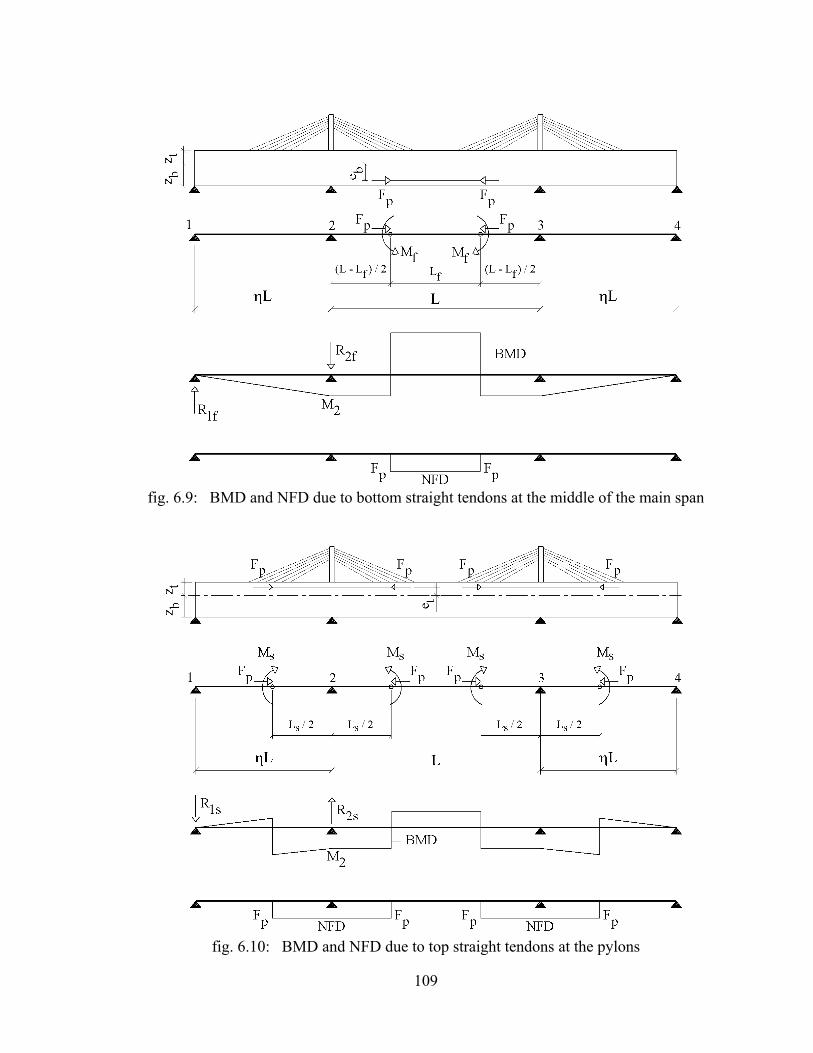
109
fig. 6.9: BMD and NFD due to bottom straight tendons at the middle of the main span
fig. 6.10: BMD and NFD due to top straight tendons at the pylons

110
fig. 6.11: BMD and NFD due to bottom straight tendons in the side spans

111
fig. 6.12: BMD and NFD due to draped tendons at the middle of the main span
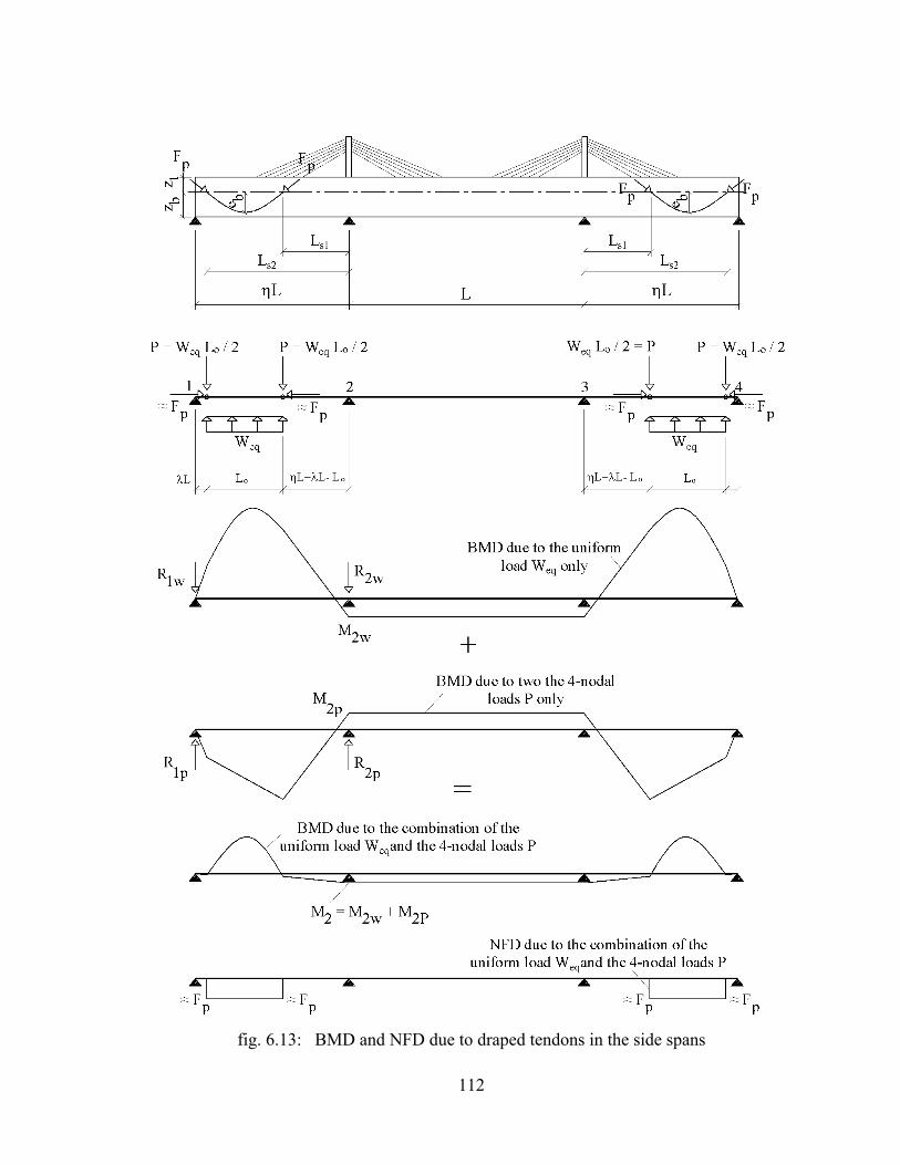
112
fig. 6.13: BMD and NFD due to draped tendons in the side spans

113
6-2-4 Preliminary design
For the preliminary design of extradosed bridges with concrete decks, the deck cross section
should be first estimated based on the record/survey of the previously constructed bridges. As a
first trial a section with a uniform height equal to L/50 for example may be assumed. The dead
load W (self weight of the assumed section plus the superimposed dead load) should then be
determined accordingly. As explained under Section 6-1, the bending moment distribution shown
in fig. 6.4 (b) will be obtained under the conditions that the dead load W is uniform, the stiffness
of the deck is uniform along the entire length of the bridge, the ratio between the side span and
the main span length is equal to 0.615 and in addition the ratio between the equivalent stay
cable forces WC and the dead load W is equal to 1.9 (refer to fig. 6.3). By hand calculations, the
force in each stay cable FDi may be determined using equation (6.28) and the normal force
distribution due to the horizontal components of the stay cable forces may be drawn along the
entire deck length accordingly.
By substituting by 0.615 and WC by 1.9W in equations (6.6) to (6.10), the following results
will be obtained:
2
2 1 2 2rW L W L W L W L
M , R R and Q209.5 8.744 4.156 8.334
- -= = = =
(6.61)
Substituting from (6.61) in equation (6.3), the bending moment at the middle of the main span
Mm2 can be calculated from the following equation:
2
m2W L
M160.7
= (6.62)
The values of the critical bending moment M2 at the pier and Mm2 at the middle of the main span
(due to the effect of dead load and the stay cable forces FDi) can be used to estimate the required
prestressing tendons. Equations (6.34) to (6.60) may be used if non concordant prestressing
tendons are planned to be used. In case concordant prestressing profiles are selected, the required
prestressing force FP may be estimated using the values of the critical bending moments M2 and
Mm2 and the distances zt and zb (= the distances between the center of gravity of the deck section
and the top and bottom fibres of the deck section respectively). It is also necessary to check that
the dimensions of the selected deck section are adequate to contain all the prestressing tendons

114
required to produce the estimated prestressing force FP. Accordingly, the bending moments and
the normal force distribution due to the selected prestressing may be calculated/drawn.
The critical sections of the deck (at the middle of the main span and at the pier) should then be
checked under the combination of the dead load, stay cable forces, prestressing forces and live
loads taking into account the instantaneous and long term prestressing losses.
The envelope of the bending moments resulting from a uniform live load q is shown in fig. 6.14.
The values of the bending moments shown in fig. 6.14 are based on the following assumptions:
- The moment of inertia of the deck cross section is constant along the entire length of the bridge.
- The ratio between the side span length and the main span length is equal to 0.615.
Based on the nos. of traffic lanes and the live load acting on each lane as required by the project
specification, the value of the load q and the corresponding maximum and minimum bending
moments may be determined accordingly. The normal forces associated with the maximum
bending moments due to live loads (due to the presence of the stay cables) may be ignored. Such
assumption is normally on the safe side.
The calculation process described above may be required to be repeated to increase the
prestressing forces or the dimensions of the selected deck cross section until satisfactory results,
to carry safely the combination of dead and live loads, are reached.
The method of calculation described above may be also used to check the plausibility of the
computer results in the detailed design stage.
fig. 6-14: Envelope of the bending moments due to uniform live load q

115
6-3 Commercial consideration related to the use of the stay cables and the concordant
prestressing cables
As explained under sections 6-1 and 6-2, a combination of stay cable forces and prestressing
forces may be targeted to nearly eliminate the bending moments under dead load. Based on the
contribution of the stay cables and the prestressing in reducing the bending moments at the
critical sections of the deck, the use of the stay cables and prestressing materials may be
evaluated commercially as will be explained in this Section, taking into account the prevailing
unit weight costs for both materials.
fig. 6.15: Bending moment distribution under the dead load W in the absence of the stay cables and the prestressing forces
fig. 6.15 shows the bending moment distribution along the entire deck length due to the dead load
W in the absence of the stay cables and the prestressing. From figs. 6.4(b) and 6.15, it may be
understood that the stay cables contribute to reduce the bending moments at the critical deck
sections at the pylon and the middle of the main span from WL2/13.727 and WL2/19.175 to
WL2/209 and WL2/160 respectively (refer also to equations (6.61) and (6.62). This means that the
stay cables serve to reduce the bending moments at the pylon and the middle of the main span by
93% and 88% respectively. In average it may be approximately stated that the stay cables reduce
the critical bending moments due to dead load by 90%.
Further, it was concluded under section 6-2-2 that the bending moment along the entire length of
the extradosed bridge may be eliminated by the use of concordant prestressing profiles.
Accordingly, it may be stated that the concordant prestressing contributes to reduce the critical
bending moments by 10%.

116
To evaluate the use of the stay cables commercially in comparison with the use of the
prestressing inside the deck section, the unit weight cost of the stay cable material is assumed to
be equal to “S” and the total weight of the stay cables material required to reduce the critical
bending moments under dead load by 90% will be referred to as “Wsc“. This means that the cost
of reducing the critical bending moments under dead load by 1% by the stay cables is equal to:
scsc
S W0.01S W
90=
.
On the other hand, it has been found from the detailed analysis of the bridge shown in Appendix
E that the weight of the concordant cable prestressing required to reduce the critical bending
moments under dead load by 10% is equal to ≈ 1.5 Wsc. By assuming that the unit weight cost of
the stay cables material is approximately equal to 3.0 times the unit weight cost of the
prestressing material, the cost of reducing the critical bending moments under dead load by 1%
by the prestressing material will be equal to: scsc
S x W )0.05 S W
3.0 x10
= .
Based on the above calculation’s approach, it may be concluded that the cost of the stay cables
material required to reduce the critical bending moments in the deck under dead load by 1% is
equal to about 20% of the cost of the prestressing material required to reduce the critical bending
moments by the same amount (1%). The above conclusion is valid only for a bridge with uniform
dead load W, uniform moment of inertia of the deck section I and side span to main span ratio
equal to 0.615.

117
CHAPTER 7
7- POSSIBLE CONSTRUCTION METHODS FOR THE EXTRADOSED BRIDGES
As explained in Chapter 5, the extradosed bridges are usually built with main spans of 100 to
200m and side spans of 50 to 150m. For such types of spans the precast segmental construction
method are considered to be most suitable. The precast segmental construction for both of the
side and main spans may be implemented by the balanced cantilever erection method.
Alternatively, the side span may be constructed by the “span by span” erection method, by using
temporary trestles if necessary and the segmental construction of the main span may follow using
the free cantilevering method.
In this Chapter, the fabrication methods for the precast segments will be briefly explained under
Section 7-1 and the common erection methods of the precast segments will be presented in
Section 7-2. Further, a proposal for the construction of extradosed bridges, using a concrete/
concrete composite deck section, will be explained in Section 7-3.
Bridges with precast concrete deck segments gained popularity among bridge designers in the last
twenty years. The precast segmental construction has been found suitable for use for approach
viaduct bridges, conventional cable-stayed bridges and in addition extradosed bridges. The
precast deck segments were used for the Ibi river extradosed bridge in Japan (completed in 2001),
the second Vivekananda extradosed bridge in India (completed in 2007) and the Canada line
extradosed LRT bridge in Canada (completed in 2009).
The deck segments can be fabricated under controlled conditions at the same time of the
construction of the bridge foundations and the substructure. As such not only the tight
construction time schedule, imposed often by the bridge owner authorities, can be met but
outstanding finishing quality for the bridge elements can be achieved as well.
The erection of deck by the use of the precast segments started in the 1960s and the first pre-
stressed concrete bridge consisting of precast segments with match cast epoxy joints was Choisy-
Le-Roi bridge over Seine River/France (fig. 7.1). The bridge was designed by Jean Muller and
constructed by the French Contractor “Campenon Bernard” in the time period 1962-1964. The
total length is equal to 131m (=37.5+55+37.5) and its deck width is equal to 28.40m [Podolny
and Muller 1992]. Precast segments were then used worldwide for conventional elevated bridges

118
and cable supported bridges. The 4.5 km Bandra Worli sea link bridge in Mumbai India
(completed in 2009) is considered to be a good example for precast segmental construction (fig.
7.2).
fig. 7.1: Choisy-Le-Roi bridge over Seine River/France [http://en.structurae.de]
fig. 7.2: Erection of precast segments for Bandra Worli Sea Link in Mumbai/India
7-1 Fabrication of Precast Segments
The concrete precast segments are fabricated normally with the “match-cast” technique which
means that every segment is cast against the preceding segment creating a matching which
permits the re-establishment of the casting geometry configuration at the erection time. The
“match casting” can be carried out either by the “short line” or the “long line” casting method
(figs. 7.3 to 7.5). It can be understood from these figures that in the “short line” method, a fixed
in place “bulkhead” and form works for two segments only are sufficient. For the “long line
method”, movable “bulkheads” and form works for several segments are normally used.

119
fig. 7.3: Pre-casting the segments using the short line method
fig. 7.4: Pre-casting the segments using the long line method
fig. 7.5: Alternative casting scheme for the long line method

120
7-2 Methods of erection of precast segments
Since the advent of the precast segments for bridges construction in the 1960s, the following
erection methods used to be followed:
- Erection of precast segments on Scaffolding.
- Erection by the balanced cantilever method.
- Span by span erection method.
- Incremental launching method.
Erection of the precast segments on scaffolding is considered normally to be the right choice in
case the bridge deck is constructed on the land and the deck is not too high (fig. 7.6). Erection of
precast segments on scaffolding may be carried out in the sea also. The precast segments in the
vicinity of the tower of Bandra cable-stayed bridge in Mumbai were erected on scaffolding as
shown in (fig. 7.7). Every segment is placed usually on a steel trolley as that shown in fig. 7.6.
The scaffolding should be provided by hydraulic and mechanical jack systems to allow the trolley
along with the precast segment to be moved in the longitudinal and transverse directions to reach
the required alignment in plan. The trolley itself should be provided with hydraulic and
mechanical jacks to allow the segment to move upwards or downwards, relative to the trolley, to
take the required alignment vertically. The precast segments may be also erected by the “span by
span erection method” as shown in fig. 7.2 or by the balanced cantilever method as shown in fig.
7. 8. The incremental launching method as developed by VSL [VSL 1977] is shown in figs. 7.9
and 7.10. In this erection method, the concrete deck is cast in segments behind the abutment.
Each segment is cast directly behind the preceding one. The segment is subsequently prestressed
and pushed forward along with the previously cast segments by a segment’s length which ranges
between 15 to 25m, using hydraulic jacks. It can be understood from fig. 7.9 that the tendons
used for launching the deck segments are connected to the rear end of the deck segments and the
horizontal jacks are bearing on the abutment. During launching the superstructure, the cross
section of the deck segment will have to carry alternating bending moments. Each cross section
moves from regions of positive bending moment into regions of negative bending moment, so
that tensile stresses occur alternately at the bottom and top fiber of the deck section. The use of
axial pre-stressing is therefore necessary to reduce the tensile stresses to the permissible value. If
the deck segments are simply launched to the first pier with no special provision to reduce the
bending moment, the hog bending moment in the first span will be in the order of six times the

121
typical hog bending moment over the pier (the ratio between WL2/2 and WL2/12). The method
used most frequently to overcome this problem is to use a light structural steel nose attached to
the leading cantilever fig. 7.10. The nose must be light to reduce the hog bending moment and
stiff enough to withstand safely the forces it has to carry. Fig. 7.10 and table 7.1 show also that
the maximum hog bending moment in the deck during construction, depends on the ratio between
the length of the nose and the span length and depends also on the unit weight of the nose relative
to the standard unit weight of the deck which normally varies between 0.10 to 0.15 [Podolny and
Muller 1992].
fig. 7.6: Erection of precast segments on scaffolding by mobile crane
fig. 7.7: Erection of precast segments on scaffolding- All precast segments are lifted at one location by a lifting frame and slid on top of the scaffolding longitudinally (used by HCC-
Contractor in India)

122
fig. 7.8: Erection of the precast segments for Bandra cable-stayed bridge with the balanced
cantilever method
fig. 7.9 Method used by “VSL” to launch the deck segments [VSL 1977]

123
fig. 7.10: Critical hog bending moment during the incremental launching of precast segments
[Podolny and Muller 1992]
Table 7.1: Effect of the steel nose length on M during the incremental launching of precast
segments [Podolny and Muller 1992]
7-2-1 Erection of deck with cross section consisting of three precast segments
The deck cross section may be fabricated out of three precast segments as shown within fig. 7.11.
The central spine precast segments can be erected on scaffolding, by the “balanced cantilever
method”, by “the span by span method or by the incremental launching method. The erected
spine segments may then be used as a platform to erect the side frame precast segments on both
sides of the previously erected spine segment. The separation of the cross section into three
lighter segments enables the use of lighter erection machines. Such type of cross section is
considered therefore to be an effective choice for the construction of extradosed bridges where
the stay cables are not arranged over the full length of the deck. Each individual side frame
segment may be lifted by a mobile crane, running on the ground or on the previously erected
spine segments. Fig. 7.12 shows the forces acting on the side frame segment during erection. The
self weight W of the side frame segment should not be transferred from the mobile crane to the
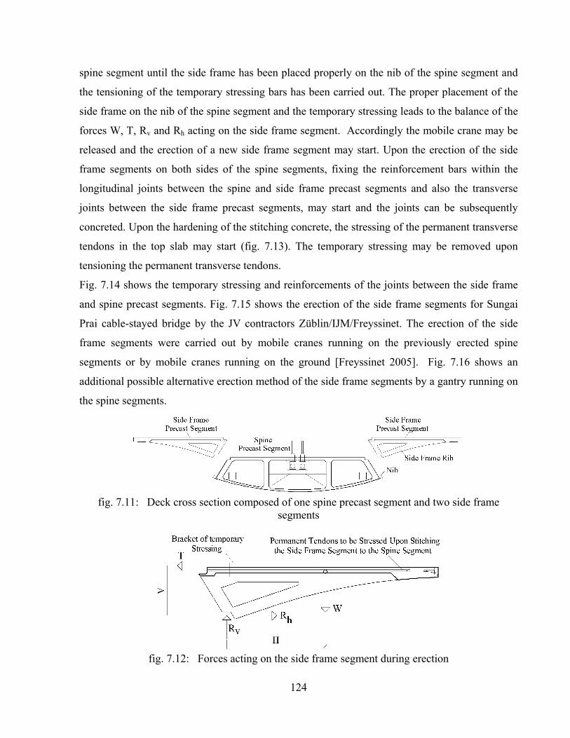
124
spine segment until the side frame has been placed properly on the nib of the spine segment and
the tensioning of the temporary stressing bars has been carried out. The proper placement of the
side frame on the nib of the spine segment and the temporary stressing leads to the balance of the
forces W, T, Rv and Rh acting on the side frame segment. Accordingly the mobile crane may be
released and the erection of a new side frame segment may start. Upon the erection of the side
frame segments on both sides of the spine segments, fixing the reinforcement bars within the
longitudinal joints between the spine and side frame precast segments and also the transverse
joints between the side frame precast segments, may start and the joints can be subsequently
concreted. Upon the hardening of the stitching concrete, the stressing of the permanent transverse
tendons in the top slab may start (fig. 7.13). The temporary stressing may be removed upon
tensioning the permanent transverse tendons.
Fig. 7.14 shows the temporary stressing and reinforcements of the joints between the side frame
and spine precast segments. Fig. 7.15 shows the erection of the side frame segments for Sungai
Prai cable-stayed bridge by the JV contractors Züblin/IJM/Freyssinet. The erection of the side
frame segments were carried out by mobile cranes running on the previously erected spine
segments or by mobile cranes running on the ground [Freyssinet 2005]. Fig. 7.16 shows an
additional possible alternative erection method of the side frame segments by a gantry running on
the spine segments.
fig. 7.11: Deck cross section composed of one spine precast segment and two side frame
segments
fig. 7.12: Forces acting on the side frame segment during erection

125
fig. 7.13: Deck cross section upon the achievement of the composite action between the spine and side frame precast segments
fig. 7.14: Temporary stressing of the side frame segments to the previously
erected spine Segments
fig. 7.15: Erection of the side frame segments by mobile cranes running on the previously erected spine segments or by mobile cranes running on the ground
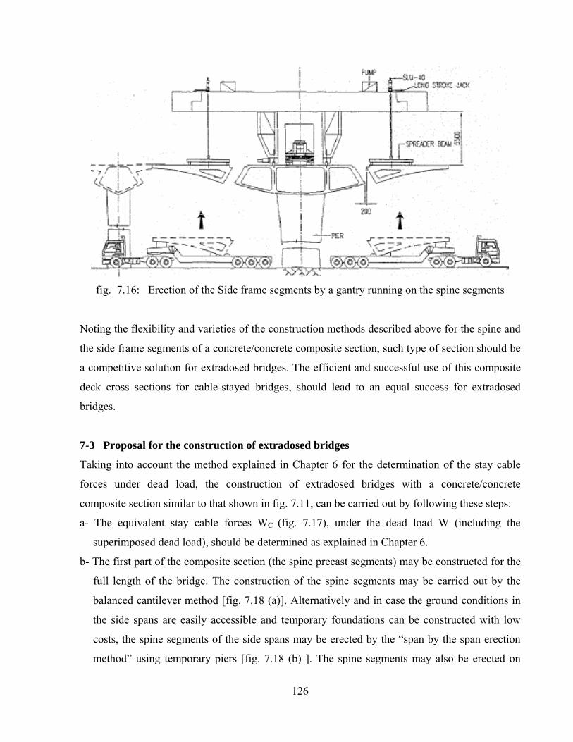
126
fig. 7.16: Erection of the Side frame segments by a gantry running on the spine segments
Noting the flexibility and varieties of the construction methods described above for the spine and
the side frame segments of a concrete/concrete composite section, such type of section should be
a competitive solution for extradosed bridges. The efficient and successful use of this composite
deck cross sections for cable-stayed bridges, should lead to an equal success for extradosed
bridges.
7-3 Proposal for the construction of extradosed bridges
Taking into account the method explained in Chapter 6 for the determination of the stay cable
forces under dead load, the construction of extradosed bridges with a concrete/concrete
composite section similar to that shown in fig. 7.11, can be carried out by following these steps:
a- The equivalent stay cable forces WC (fig. 7.17), under the dead load W (including the
superimposed dead load), should be determined as explained in Chapter 6.
b- The first part of the composite section (the spine precast segments) may be constructed for the
full length of the bridge. The construction of the spine segments may be carried out by the
balanced cantilever method [fig. 7.18 (a)]. Alternatively and in case the ground conditions in
the side spans are easily accessible and temporary foundations can be constructed with low
costs, the spine segments of the side spans may be erected by the “span by the span erection
method” using temporary piers [fig. 7.18 (b) ]. The spine segments may also be erected on

127
scaffolding if practically possible. Upon the erection of the spine segments in the side spans,
the spine segments of the main span segments may be erected by the progressive placement
method (free cantilevering method from one side only). The stay cables may be installed in
two stages. The first stage installation forces may be made to carry the concrete weight W’
only of the composite section (self weight of the spine + side frame segments) without the
superimposed dead load.
c- The side frame segments on both sides of the spine segments can be erected as shown in figs.
7.14 to 7.16.
Upon the erection of all side frame segments, the longitudinal and transverse joints between
the spine segments and the side frame segments can be concreted. Accordingly, the stay cables
forces at this stage, will be equal to the corresponding stay cable forces under 100% of the
dead load (including the superimposed dead load) multiplied by a factor equal to W’/W (i.e.
W’C / WC = W’ / W). Similarly, the “frozen” bending moment distribution in the spine
segments at this stage (shown with dotted line in fig. 7.17) will be equal to the bending
moment distribution under 100% of the dead load multiplied by a factor equal to W’/W.
It is also to note that the “frozen” bending moment, carried by the spine segment alone, can be
reduced considerably in case concordant prestressing cable profiles are used within the spine
segments, as explained in Section 6-2-2, and stressed prior to casting the in-situ concrete
stitching between the spine and side frame segments (i.e. prior to the achievement of the
composite section properties).
d- Upon the hardening of the in-situ concrete in the joints between the precast segments, the
permanent transverse stressing between the side frames and the spine segments, may be
carried out (refer to fig. 7.13). Subsequently, the superimposed loads may be placed.
e - The stay cable forces are to be re-stressed to the final desired forces.
It is also important to note that temporary stay cables may be feasible to erect the segments in the
central part of the main span where there are normally no permanent stay cables available (fig.
7.18). The use of the temporary stay cables may be found easier and more economical as
compared to the use of excessive numbers of temporary prestressing bars between the deck
segments. The anchorage of the temporary stay cables at the deck and the pylon head levels may
be arranged as shown in figs. 7.19 and 7.20. The stressing of the temporary stay cables may be

128
carried out at the deck level by using stressing bars [fig 7.19 (a)] and floating steel anchor beams.
The anchorage of the temporary stay cable at the pylon head should be provided with two
independent pen assemblies allowing the anchor to rotate vertically and horizontally to orient the
temporary stay cable to different anchorage locations at the deck level. Such arrangements was
used by “Larsen & Toubro and VSL” for the construction of Wadi Abdound bridge in
Amman/Jordan (fig. 7.20).
fig. 7.17: Proposed stay cable forces and bending moment distribution during the construction of extradosed bridges with concrete/concrete composite deck
fig. 7.18: Possible construction method of extradosed bridges using temporary stay cables

129
fig. 7.19: Anchorage of the temporary stay cable at the deck and pylon head levels
fig. 7.20: Use of temporary stay cables for the construction of Wadi Abdoun bridge in Jordan

130
131
CHAPTER 8
8- CONCLUSIONS AND RECOMMENDATIONS
8-1 Conclusions
The determination of the desired stay cable forces under dead load for cable-stayed bridges with
composite decks (steel/concrete) or (concrete/concrete) may be carried out by the continuous
beam method, similar to the conventional cable-stayed bridges with concrete-only deck sections.
The stay cables should be installed in such a way that the vertical components of the stay cable
forces will be equal to the vertical reaction forces of an imaginary continuous beam with rigid
supports at the anchorage points of the stay cables at the deck level. The “step by step
construction stage analysis” for cable-stayed bridges with composite decks, has however shown
that the installation of the stay cables “to length”, using the stay cable forces obtained from the
continuous beam method, will not lead to the desired end results. The deviation between the
resulting and the desired stay cable forces will depend mainly on the ratio between the moment of
inertia of the first part of the composite section to moment of inertia of the total composite
section “Is/Icomp”. The deviation will be also affected by the vertical shift between the center of
gravity of the first part of the composite section to the center of gravity of the total composite
section “e”. The lower the ratio “Is/Icomp“ and the higher the value of “e”, the higher the deviation
will be between the resulting and the desired stay cable forces. The end results will be further
affected by the time dependent forces due to creep and shrinkage of the concrete components of
the composite section. A new construction method for cable-stayed bridges with composite decks
is therefore proposed in this research work to achieve the desired forces and bridge alignment
taking into account the effects of “Is/Icomp“ , “e” and the time dependant forces due to creep and
shrinkage of the concrete material.
Further and based on a survey and a study of the previously constructed extradosed bridges, it
was found out that there is a need to establish a method for the determination of the stay cable
forces under dead load for this type of bridges. In this research work a proposal has been made
for this purpose including recommended methods for the determination and handling the required
internal and/or external prestressing within the deck cross section. The proposed method for the
form finding of the extradosed bridges, is suitable for use for bridges with concrete, steel or
composite deck sections. For extradosed bridges with concrete decks, a combination of the stay

132
cable forces and the prestressing forces inside the deck section may be selected to eliminate the
bending moment due to dead load along the entire length of the deck.
8-2 Recommendations
The method established in this research work to determine the stay cable forces under dead load
for extradosed bridges is based on the following assumptions:
A- The dead load and the moment of inertia of the deck section are constant along the entire
length of the deck.
B- The pylon’s height above the deck level is equal to 1/10 of the main span L.
C- The stay cables support 4 x 0.2 L of the entire deck length.
The effects of changing the above assumptions on the results obtained in this research work may
be investigated. A feasibility study may be further carried out to quantify the possible savings, if
any, in case varying deck depths are used taking into consideration the related costs of the
necessary prestressing quantities.
Finally, reference is made to the “active macrosystem” and the “active microsystem” described
within [Schlaich and Korvink 2000]. In the “active macrosystem” computer controlled jacks are
located at the end of each stay cable. These computer controlled jacks are thought to continuously
and automatically re-stress or de-stress the stay cables to reduce the deck deflection due to live
loads. The live loads and the re-stressing/de-stressing operations, are sensed by small sensors and
the final action is thought to be carried out by conventional “large” hydraulic jacks (hence the
name “macrosystem”). The “active microsystem” is a further enhancement to the “active
macrosystem” to allow the bridges to be more “autonomous”, where the final action is to be
executed also by “small” tools. As suggested, the “active microsystem” would require the stay
cables to be fabricated out of lightweight multifunctional layer materials, consisting of load
bearing carbon fibers combined with “active” materials such as piezo-ceramics or polymer gels.
The achievement of a real progress towards the implementation of the above mentioned “active
macrosystem” or the “active microsystem”, would lead to a considerable reduction of the deck
stresses due to live loads and, therefore, lighter deck cross sections may be achieved.
133
LIST OF FIGURES
fig. 1.1: Desired bending moment distribution under dead load for conventional cable-stayed bridges (1) fig. 1.2: Composite deck steel/concrete used for the design of Ting Kau bridge in Hong Kong by“schlaich bergermann und partner” (1) fig. 1.3: Composite deck concrete/concrete used for the design of Sungai Prai cable-stayed bridge in Penang/Malaysia by “Dar Consultants” (2) fig. 1.4: Common configuration of extradosed bridges (2) fig. 1.5: Proposed bending moment distribution under dead load for extradosed bridges (3) fig. 2.1: Parallel bar cables [Walter et al. 1999] (6) fig. 2.2: Locked coil strand (7) fig. 2.3: Stay Cables with Parallel Wires cables/ BBR-HiAm system [www.bbrnetwoork.com] (8) fig. 2.4: Swaging the wires prior to grouting the stay cable head (9) fig. 2.5: Anchorage of the wires at the stay cable head (9) fig. 2.6: Testing of the fabricated stay cable with its full length prior to its delivery to the erection site (9) fig. 2.7: Uncoiling and pulling the stay cable ends to the tower head and along the deck level (10) fig. 2.8: Pulling the Stay cable to the deck soffit using pulling rods and temporary strands anchored at the pulling rod head (10) fig. 2.9: Equipments used for installation and stressing of stay cables (parallel wire cables system) (10) fig. 2.10: Components of Freyssinet parallel strand cables [www.freyssinetusa.com] (11) fig. 2.11: Cross sections through the strand bundle and the mono-strand used for Freyssinet stay cable system [Freyssinet 1999] (12) fig. 2.12: Anchorage components of Freyssinet parallel strand stay cable system [www.freyssinetusa.com] (13) fig. 2.13: Anchorage block used for Freyssinet stay cable system (13) fig. 2.14: Installation of the parallel strand cables with the isotension method (schematic) (14) fig. 2.15: Isotension principle diagram [Freyssinet 1999] (14) fig. 2.16: Threading the strands from the anchorage location on the side span side to the anchorage location on the main span side through the deviator saddle (schematic) (15) fig. 2.17: Threading the stay cables strands for Sungai Prai cable-stayed bridge in Penang/Malaysia (15) fig. 2.18: Installation of the parallel strand cable by the ''strand by strand'' method (16) fig. 2.19: Passive Anchorage at deck level (16) fig. 2.20: Active anchorage at deck level [Leonhardt and Zellner 1980] (16) fig. 2.21: Stay cable anchorages inside the tower head (19) fig. 2:22: Anchorage of stay cables using external steel box (19) fig. 2.23: Tower Head of Ting Kau Bridge (19) fig. 2.24: Overcrossing of stay cables [Leonhardt and Zellner 1980] (19) fig. 2.25: Anchorage of the stay cables at the tower head of Worli cable-stayed bridge in Mumbai/India (20)

134
fig. 2.26: Anchorage of stay cable at the tower head by the use of steel saddle and rigid cement grout (20) fig. 2.27: Placement of steel saddles within the tower head prior to concreting (21) fig.2.28: The prefabricated saddles used for Sungai Muar cable-stayed Bridge in Johor /Malaysia [Lecinq et al. 2005] (21) fig. 2.29: Sungai Muar Cable-stayed Bridge in Johor/Malaysia [Lecinq et al. 2005] (21) fig. 2.30: Possible structural systems for conventional cable-stayed bridges (24) fig. 2.31: Load case for maximum back stay forces (26) fig. 2.32: Load case for minimum back stay forces (26) fig. 2.33: Relationship between the ratio of the side span and the main span & the ratio between the live load and the dead load [Gimsing and Georgakis 2011] (26) fig. 2.34: Effect of the stay cable sag on its effective elastic modulus [Walter et al. 1999] [Freyssinet 1999] (28) fig. 3.1: Desired bending moments, shear and normal force distributions under dead load, for cable-stayed bridges with concrete deck cross sections (30) fig. 3.2: Creep effect on a simple concrete beam (33) fig. 3.3: Creep effect on a continuous concrete beam (40) fig. 3.4: Common construction methods for cable-stayed bridges (42) fig. 3.5: Effect of the live load on the selection of the stay cable forces under dead load [Svensson 2012] (43) fig 3.6: Application of the “influence matrix for stay cable forces” method to achieve specific desired stay cable forces under dead load (45) fig 3.7: Application of the “influence matrix for stay cable forces” method to achieve a specific desired bending moment distribution along the deck length under dead load (48) fig 3.8: Application of the “influence matrix for stay cable forces” method to achieve a specific desired vertical profile for the deck under dead load (49) fig. 4.1: Time dependent effect due to vertical loads (Type I) (55) fig. 4.2: Additional time dependent effect in case of composite deck (Type II) (56) fig. 4.3: Installation of stay cables to “length” (57) fig. 4.4: Rion Antirion bridge in Greece (completed in 2004) [http://en.wikipedia.org] (58) fig. 4.5: Rion Antirion bridge during construction [http://en.structurae.de] (58) fig. 4.6: Construction methods for composite section in two stages (schematic) [Schlaich 2001] (59) fig. 4.7: Bending moment distribution along the deck segment under erection prior to the achievement of the composite section properties [Schlaich 2001] (61) fig. 4.8: Comparison between the erection cycle of construction methods nos. (1) and (4) (63) fig. 4.9: Cable supported beam with a rectangular cross section constructed in two stages (66) fig. 4.10: Application of the construction methods nos. 2 and 3 on a cables supported beam (69) fig. 4.11: Effect of the ratio Is/ Icomp on the vertical deflection profile of the completed structure in case the cables are installed ''to length'' with construction method no. 4 (71) fig.4.12: Effect of the ratio Is/ Icomp on the bending moment distribution of the completed

135
structure in case the cables are installed ''to length'' with construction method no. 4 (71) fig. 4.13: Comparison between construction methods 4 or 5 with construction method 1 (75) fig. 5.1: Common configuration of prestressed box girder bridges and conventional cable-stayed bridges (77) fig. 5.2: Common configuration of extradosed bridges (78) fig. 5.3: Arrêt-Darré viaduct as proposed by J. Mathivat in 1988 [Mermigas 2008] (79) fig. 5.4: Ganter bridge, Switzerland completed in 1980 (completed in 1980) [www.highestbridges.com] (79) fig. 5.5: Cables configuration for extradosed bridges (80) fig. 5.6: Strength criterion and fatigue criterion for the design of stay cables (81) fig. 5.7: Relationship between the dead load permissible stress w and the ratio q/w [Walter et al. 1999] (82) fig. 5.8: Allowable stresses for stay cables of extradosed bridges versus the stress variation due to live loads (83) fig. 5.9: Typical fatigue curve of a cable stay [SETRA 2002] (84) fig. 5.10: Fatigue load Model 3 as defined within Eurocode EN 1991-2-2003 + AC:2010 (85) fig. 5.11: Ibi River bridge/bridge with short piers [Kasuga 2006] (86) fig. 5.12: Supporting system between the deck and the piers (86) fig. 5.13: Himi bridge in Japan with high piers [Kasuga 2006] (87) fig. 5.14: Second Manama-Muharraq crossing in Bahrain during construction [www.archirodon.net] (87) fig. 5.15: Sliding connections at the middle of the main spans (87) fig. 6.1: The BMD for cable-stayed bridges along the deck elements under dead load in comparison with the proposed BMD of an extradosed bridge (90) fig. 6.2: Method for the calculation of the desired equivalent stay cable forces WC (93) fig. 6.3: Determination of the ideal values of and WC / W (95) fig. 6.4: Method for the calculation of the desired stay cable force FDi as per equation (6.29) (99) fig. 6.5: Use of a concordant prestressing cable profile for continuous beams (101) fig. 6.6: Behavior of continuous beam on springs under the effect of the equivalent prestressing forces (102) fig. 6.7: Prestressing configurations for extradosed bridges (104) fig. 6.8: Method for the calculation of the desired stay cable force FDi taking into account the effect of the prestressing forces as per equation (6.33) (105) fig. 6.9: BMD and NFD due to bottom straight tendons at the middle of the main span (109) fig. 6.10: BMD and NFD due to top straight tendons at the pylons (109) fig. 6.11: BMD and NFD due to bottom straight tendons in the side spans (110) fig. 6.12: BMD and NFD due to draped tendons at the middle of the main span (111) fig. 6.13: BMD and NFD due to draped tendons in the side spans (112) fig. 6.14: Envelope of the bending moments due to uniform live load q (114) fig. 6.15: BMD under the dead load W in the absence of the stay cables and the prestressing forces (118) fig. 7.1: Choisy-Le-Roi bridge over Seine River/France [http://en.structurae.de] (118) fig. 7.2: Erection of precast segments for Bandra Worli Sea Link in Mumbai/Indi (118) fig. 7.3: Pre-casting the segments using the short line method (119)

136
fig. 7.4: Pre-casting the segments using the long line method (119) fig. 7.5: Alternative casting scheme for the long line method (119) fig. 7.6: Erection of precast segments on scaffolding by mobile crane (121) fig. 7.7: Erection of precast segments on scaffolding- All precast segments are lifted at one location by a lifting frame and slid on top of the scaffolding longitudinally (used by HCC- Contractor in India) (121) fig. 7.8: Erection of the precast segments for Bandra cable-stayed bridge with the balanced cantilever method (122) fig. 7.9: Method used by “VSL” to launch the deck segments [VSL 1977] (119) fig. 7.10: Critical hog bending moment during the incremental launching of precast segments [Podolny and Muller 1992] (123) fig. 7.11: Deck cross section composed of one spine precast segment and two side frame segments (124) fig. 7.12: Forces acting on the side frame segment during erection (124) fig. 7.13: Deck cross section upon the achievement of the composite action between the spine and side frame precast segments (125) fig. 7.14: Temporary stressing of the side frame segments to the previously erected spine Segments (125) fig. 7.15: Erection of the side frame segments by mobile cranes running on the previously erected spine segments or by mobile cranes running on the ground (125) fig. 7.16: Erection of the side frame segments by a gantry running on the spine segments (126) fig. 7.17: Proposed stay cable forces and bending moment distribution during the construction of extradosed bridges with concrete/concrete composite deck (128) fig. 7.18: Possible construction methods of extradosed bridges using temporary stay cables (128) fig. 7.19: Anchorage of the temporary stay cable at the deck and pylon head levels (129) fig. 7.20: Use of temporary stay cables for the construction of Wadi Abdoun bridge in Jordan (129)
137
REFERENCES
BBR: HiAm CONA Strand Stay Cable System, Elegance and Strength, the extended HiAm CONA family. www.bbrnetwork.com, 2011. Bergermann, R.; Schlaich M.: Die Ting Kau Schrägkabelbrücke in Hong Kong. Bauingenieur, BD. 74, Nr. 10- Oktober, 1999. Bergermann, R.; Schlaich M.: Ting Kau Bridge, Hong Kong. Structural Engineering International 3/96, PP. 152-154,1996. Benaim, R.: The Design of Prestressed Concrete Bridges, concepts and principles. Taylor & Francis, London and New York, 2008. Eurocode 1: Einwirkungen auf Tragwerke, Teil 2, Verkehrslasten auf Brücken, Deutsche Fassung. EN 1991-2:2003, AC 2010, Beuth Verlag, GmbH, 10772, Berlin, 2011. Freyssinet: Segmental bridge construction methods and survey procedures. Association of Consulting Engineer Malaysia Seminar, Kuala Lumpur, Malaysia 21st – 22nd June, 2005. Freyssinet: Stay Cables, Freyssinet catalogue for stay cable system. September, 1999. Gabrow, M.: Construction Stage Analysis of Cable-Stayed Bridges. Thesis at the faculty of the technical university of Hamburg-Harburg, Hamburg, Germany, June, 2004. Gimsing, N.; Georgakis, C.: Cable Supported Bridges, concept and design (Third Edition). John Wiley & Sons, Chichester, UK, 2011. Ghali, A.; Favre, A.: Concrete Structures, Stresses and Deformations (Second edition). E & FN Spon, London, UK, 1994. Herzog, M.: Beispiele prüffähiger Festigkeitsnachweise mit Baupraktischen Näherungen. ISBN 3-8041-2034-2, Werner-Verlag, Düsseldorf, Germany, 1994. Hurst, M.: Prestressed Concrete Design, (Second Edition). E & FN SPON, London and New York, 1998. Iles, D.: Design Guide for Continuous Composite Bridges, 1 – Compact Sections. The Steel Construction Institute, UK, 1989. Kasuga, A.: Extradosed bridges in Japan. Structural Concrete, 7(3), 91-103, 2006. Kasuga, A.: Construction of extradosed bridges in Japan. PWD Malaysia/JICA, Kuala Lumpur, August, 2002. Lecinq, B.; Petit, S.; Zivanovic, I.: Cohestrand stay cables and suspension cables for an extended durability. fib Symposium “Keep Concrete Attractive”, Budapest, 2005.
138
Leonhardt, F.: Vorlesungen über Massivbau, Teil 5, Spannbeton. Springer-Verlag, Berlin, Heidelberg, New York, 6. Nachdruck, 2004. Leonhardt, F.; Zelner, W.: Cable-Stayed Bridges. IABSE SURVEYS, S-13/80, 1980. Lin, T. Y.; Burns, N: Design of prestressed concrete structures (3nd Edition). John Wiley & Sons, 1989. Mathivat, J.: The Cantilever Construction of Prestressed Concrete Bridges. English translation by C. J. Emberson, John Wiley & Sons, 1983. Maxfield, B.: Engineering With Mathcad, Using Mathcad to Create and Organize your Engineering Calculations. Butterworth-Heinemann, Oxford, UK, 2006. Mermigas, K.: Behavior and Design of Extradosed Bridges. Thesis at Graduate Department of Civil Engineering, University of Toronto, 2008. Meiss, K.: Anwendung von Strukturoptimierungsmethoden auf den Entwurf mehrfeldriger Schrägseilbrücken und Extradosed Bridges. Dissertation Universität Stuttgart, Institut für Leichtbau Entwerfen und Konstruieren, 2007. Menn C.: Stahlbeton Brücken. Springer Verlag, 1990.
Midas: Civil Software, Integrated Solution System for Bridge and Civil Engineering. http://en.midasuser.com, 2011. Mosley, B.; Bungey, J.; and Hulse, R.: Reinforced concrete design to Eurocode 2, (Sixth Edition). Palgrave Macmilian, New York, 2007. Mutsuyoshi, H.; Hai, N.; Kasuga, A.: Recent technology of prestressed concrete bridges in Japan. IABSE-JSCE Joint Conference on Advances in Bridge Engineering-II, Dhaka, Bangladesh, August 8-10, 2010. Ogawa, A.; Kasuga, A.: Extradosed bridges in Japan. FIP notes, 2, 11-15, 1998. Pedrozzi, P.: A Software Tool for the Analysis, Design and Monitoring of Cable-stayed Bridges. Institut für Baustatik und Konstruction (ibk), ETH Zürich, August, 2004. PFEIFER: PFEIFER-Zugglieder/PFEIFER-Tension Members. www.pfeifer.de, 2010. Podolny, W.; Muller, J.: Construction And Design of Prestressed Concrete Segmental Bridges. Krieger Publishing Company, 1992.
Post-Tensioning Institute (PTI): PTI Guide Specifications, Recommendations for Stay Cable Design, Testing and Installation. 2001.
139
Rombach, G.: Precast segmental box girder bridges with external prestressing, design and construction. Technical university Hamburg-Harburg, 2002. Schlaich, J.: Conceptual Design of bridges, More Variety. Bridge Engineering Conference, Sharm El-Sheikh, Egypt, Egyptian Society of Engineers, organized by ESE, IABSE and fib, 2000.
Schlaich, M.; Abdalsamad, A.; Annan, R.: Großversuche zur Ermüdung von Litzenseilen auf Umlenksätteln für Schrägseilbrücken. Bautechnik 89 (11), S. 777–785, 2012. Schlaich, M.: Erection of Cable-stayed Bridges Having Composite Decks With Precast Concrete Slabs. Journal of Bridge Engineering, PP. 333-339, September / October, 2001.
Schlaich, M.; Korvink J.: Autonomous bridges. Bridge Engineering Conference, Sharm El-Sheikh, Egypt. Egyptian Society of Engineers, organized by ESE, IABSE and fib, 2000. SETRA: Cable stays- Recommendations of French interministerial commission on Prestressing. Service d’Etudes Techniques des Routes et Autoroutes, Juin, 2002. SOFISTIK: Finite Element Software, Bridge Design. www.sofistik.com, 2012. Srinivasan, G.: Design for construction, economy and elegance in concrete bridges. Structural Concrete, 8. No. 4, PP. 213-217, 2007. Srinivasan, S.: Design and Construction of Modern Concrete Bridges. The Structural Engineer, PP. 31-36, May, 2004.
Srinivasan, S.: Award-winning design for two bridges in the middle east, Concrete Engineering international, PP. 20-23, May, 2004.
Srinivasan, S.: The philosophy of Design and Construction of Concrete Bridges. 13th Shri. S. B. Joshi Memorial Award Function, Alumni Association of College of Engineering, Pune 411005, India, October, 2007. Svensson, H.: Cable-Stayed Bridges / 40 Years Experience Worldwide. Ernst & Sohn, 2012. VSL: Stay Cable Systems, VSL in the Saddle, Flower Anchorage, LRT Dubai. VSL International LTD. Berne/Switzerland, The VSL news magazine, issue one, 2008. VSL: The Incremental Launching Method in Prestressed Concrete Bridge Construction. VSL International LTD, Berne/Switzerland, Gerber A.G Schwarzenburg, April, 1977. Walther, R.; Houriet, B.; Isler, W.; Moia, P.; Klein, J.: Cable-stayed Bridges (2nd Edition). Thomas Telford Publishing, London, 1999.
140
APPENDIX A
Application of the continuous beam method for the determination of the stay cable forces under dead load
(refer to Section 3-1)
Software used: [SOFISTK 2012] & [Midas 2011]

141
Elastic modulus of the concrete beam Ec = 35000 MPa
Elastic modulus for the cable material Es = 200000 MPa
fig. A.1: Geometry of a simple cable-supported structure
Objective:
The desired cable forces at time infinity should have vertical components equal to the reaction
forces of an equivalent continuous beam (fig. A.2).
fig. A.2: Imaginary continuous beam equivalent to the cable-supported structure
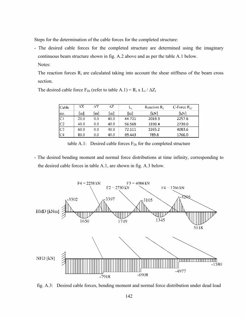
142
Steps for the determination of the cable forces for the completed structure:
- The desired cable forces for the completed structure are determined using the imaginary
continuous beam structure shown in fig. A.2 above and as per the table A.1 below.
Notes:
The reaction forces Ri are calculated taking into account the shear stiffness of the beam cross
section.
The desired cable force FDi (refer to table A.1) = Ri x Li / Zi
table A.1: Desired cable forces FDi for the completed structure
- The desired bending moment and normal force distributions at time infinity, corresponding to
the desired cable forces in table A.1, are shown in fig. A.3 below.
fig. A.3: Desired cable forces, bending moment and normal force distribution under dead load

143
- The cross section of each cable may be calculated as shown in table A.2 below based on the
forces FDi in table 1, assuming that the cables are fabricated from 7-wire strands and that each
strand has a cross sectional area A = 150 mm2. It is also assumed that the maximum stress in
the cable material due to the dead load W is equal to, say, 300 MPa.
- The beam segments B1 to B4 are defined in the computer model with the rectangular cross
section A-A shown in fig. A.1 and the cables are defined with the cross sectional areas Asi
calculated in table A.2.
The unstressed lengths Lui of the cables C1 to C4 are calculated in table A.2 below by using
the following formula:
( )
i iui
i Di
s si
L LL
1 F1
E A
= =æ ö+ e ÷ç ÷+ç ÷ç ÷çè ø
where :
Li = the stressed length of the cable
si = elastic strain of the cable due to the desired stay cable force FDi
Asi = the cross sectional area of each cable (refer to table A.2).
Es = the elastic modulus for the cable material.
table A.2: Un-stressed lengths Lui of the cables C1 to C4
- For the beam segments: to counterbalance the elastic shortenings C-el (resulting from the normal
force Ni in fig. A.3), the expected shortening due to creep C-cr and the expected shortening due
to shrinkage C-sh , each beam segment is to be assigned an “elongation strain” Ci equal to :
i iCi C el C cr C sh
C C C C
N N 0.1
E A E A 1000- - -e = e e e = + f +

144
where is equal to the creep coefficient (assumed in this example equal to 1.5), Ni is equal to
the normal force acting on each beam segment as per fig. A.3, Ac is equal to the beam cross
sectional area (Ac = 2 m2), C-cr is equal to the creep strain due to the normal force Ni and C-sh
is equal to the estimated shrinkage strain of the beam segments (assumed in this example equal
to 0.1mm/m). EC is the elastic modulus for the concrete material = 35000 MPa.
table A.3: Initial elastic, creep and shrinkage strains of the beam segments
2- Erection Stages
The cables C1 to C4 are introduced in the “Construction Stage Analysis Model” with the un-
stressed lengths calculated in table A.2.
The beam segments (B1 to B4) are introduced in the model in 4-stages with 4-equal lengths (each
=20m). Each new beam segment is introduced tangential to the previously erected segment and
with longer lengths as per the values Lc calculated in table A.3.
Figs. A.4 and A.5 show, for example, the computer results after the installation of the cable C2.
fig. A.4: The “Construction Stage Analysis Model” after the introduction of the beam segments B1 & B2 and the cables C1 & C2
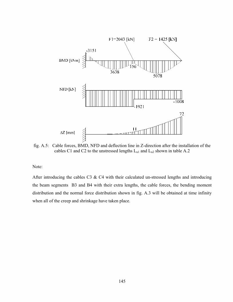
145
fig. A.5: Cable forces, BMD, NFD and deflection line in Z-direction after the installation of the
cables C1 and C2 to the unstressed lengths Lu1 and Lu2 shown in table A.2
Note: After introducing the cables C3 & C4 with their calculated un-stressed lengths and introducing
the beam segments B3 and B4 with their extra lengths, the cable forces, the bending moment
distribution and the normal force distribution shown in fig. A.3 will be obtained at time infinity
when all of the creep and shrinkage have taken place.

146
APPENDIX B
Application of the proposed construction method no. (5) on a simple cable supported beam with composite cross section
(refer to Section 4-3-4)
Software used: [SOFISTK 2012] & [Midas 2011]

147
fig. B.1: Geometry of a cable-supported beam with a composite cross section
fig. B.2: Cross section A-A

148
Table B.1: Properties of the composite cross section shown in fig. B.2 above
The desired cable forces, bending moment distribution and normal force distribution, at time
infinity under dead load, are similar to that shown in fig. A.3 in Appendix A.
If the elements of the composite section (steel + concrete) of each beam segment are planned to
be erected in two stages, each stay cable should be installed in two stages. The first stage
installation force should be determined in such a way that the “frozen” bending moment
distribution in the steel-only section will be as that shown in fig. B.3 (refer to section 4-3-2).
fig. B.3: “frozen” bending moment distribution after the first stage installation of the cable

149
The first stage installation force F1 of the cable may be calculated by using the following
equation:
13 W L 1
F3 e8 sin ( ) 1 cot ( )2 L
æ ö÷ç ÷ç ÷ç ÷ç= ÷ç ÷çq ÷ç ÷+ q ÷çè ø
(B.1)
Accordingly, the first stage installation forces for the cables C1 to C4 will be equal to 826, 1030,
1294 and 1582kN respectively.
The beam segments B1 to B4 may be initially introduced in the “Construction Stage Analysis”
model, longer, as per table B.2, to counterbalance the sum of the shortening due to elastic strains
noting that the effect of creep and shrinkage will be dealt with separately later below.
Table B.2 Initial elongation of the beam segments B1 to B4 in the computer model
After the first stage installation of the cable, the composite action between the steel section and
the concrete slab shown in fig. B.2 can be achieved and the cable can be shortened further to the
unstressed lengths Lui shown in table A.2 in Appendix A. Figs.
B.4 and B.5 show the bending moment distribution along the beam segments after the first and
the second stage installation forces of cable no. C2.
fig. B.4: Cable forces and BMD after the first stage installation of cable C2

150
fig. B.5: Cable forces and BMD after the second stage installation of cable C2 to the unstressed
length Lu2
Elastic longitudinal strains of the beam segments
Table B.3 Elastic longitudinal strains of the beam segments (calculated at the C.G of the steel
only section and the C.G of the composite section)
Note: For the calculation of s-beam (steel beam elastic strain) in table B.3, the normal force is taken
from the stage of the loading configuration shown in fig. B.3. As for comp-beam (composite beam
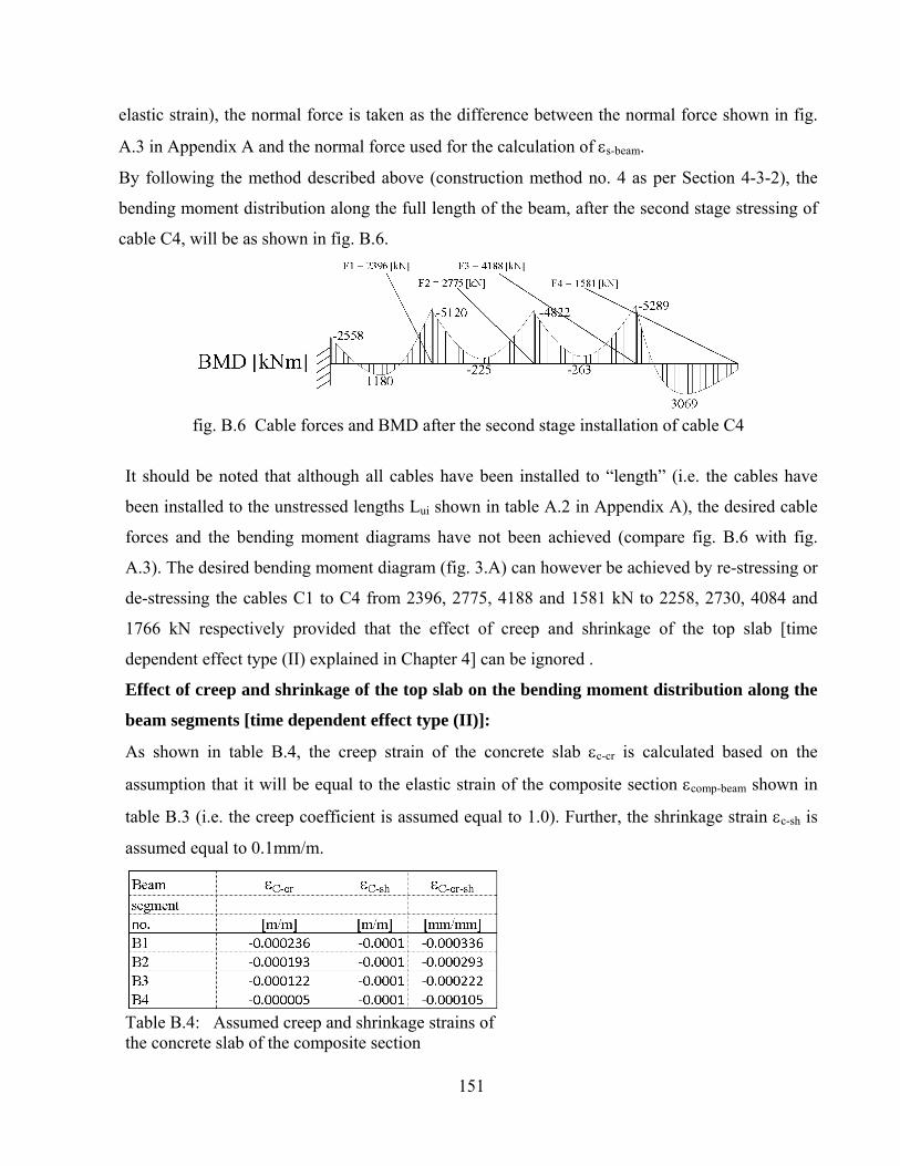
151
elastic strain), the normal force is taken as the difference between the normal force shown in fig.
A.3 in Appendix A and the normal force used for the calculation of s-beam.
By following the method described above (construction method no. 4 as per Section 4-3-2), the
bending moment distribution along the full length of the beam, after the second stage stressing of
cable C4, will be as shown in fig. B.6.
fig. B.6 Cable forces and BMD after the second stage installation of cable C4
It should be noted that although all cables have been installed to “length” (i.e. the cables have
been installed to the unstressed lengths Lui shown in table A.2 in Appendix A), the desired cable
forces and the bending moment diagrams have not been achieved (compare fig. B.6 with fig.
A.3). The desired bending moment diagram (fig. 3.A) can however be achieved by re-stressing or
de-stressing the cables C1 to C4 from 2396, 2775, 4188 and 1581 kN to 2258, 2730, 4084 and
1766 kN respectively provided that the effect of creep and shrinkage of the top slab [time
dependent effect type (II) explained in Chapter 4] can be ignored .
Effect of creep and shrinkage of the top slab on the bending moment distribution along the
beam segments [time dependent effect type (II)]:
As shown in table B.4, the creep strain of the concrete slab c-cr is calculated based on the
assumption that it will be equal to the elastic strain of the composite section comp-beam shown in
table B.3 (i.e. the creep coefficient is assumed equal to 1.0). Further, the shrinkage strain c-sh is
assumed equal to 0.1mm/m.
Table B.4: Assumed creep and shrinkage strains of the concrete slab of the composite section

152
The effect of the creep and shrinkage of the concrete slab on the bending moment distribution
along the beam segments may be calculated by using the model shown in fig. B.7. It is assumed
further, for simplicity of the calculations, that the creep and shrinkage effects will start to take
place after carrying out the second stage stressing of cable C4.
fig. B.7: Creep and shrinkage effect on the composite cross section
- C-cr = the “unrestrained” creep strain of the concrete slab.
- C-sh = the “unrestrained” shrinkage strain of the concrete slab.
- C-cr-sh = C-cr + C-sh
- cr-sh = the resultant effect of creep and shrinkage on the composite section at the level of the
centre of gravity of the composite section as shown in the above sketch.
- A1-B1 would move to A2-B2 under the effect of creep and shrinkage, in case the concrete slab is
not restrained by the steel section. Due to the restraining action of the steel beam, the line A1-
B1-C1 will move to A3-B3-C3.
In the computer model, the strain C-cr-sh ( = C-cr + C-sh ) may be defined for each beam segment
with the values shown in table B.3 as a rectangular block at distances of 207 and 457mm from the
C.G of the composite section as shown in fig. B.7. Accordingly, the effect of the creep and
shrinkage on the cable forces and bending moment distribution is shown in fig. B.8.

153
fig. B.8: Net effect of creep and shrinkage of the concrete slab on the cable forces and bending
moment distribution
Note:
More accurate results for the bending moment distribution due to creep and shrinkage, can be
obtained if the calculations are performed in small time intervals with partial creep and shrinkage
coefficients.
Referring to figs. B.6, B.8 and A.3, the desired bending moment distribution shown in fig. A.3
can be achieved by re-stressing or de-stressing the cables C1 to C4 from (2396+45), (2775+42),
(4188-10) and (1581-82) to 2258, 2730, 4084 and 1766 kN respectively
After carrying out the above mentioned re-stressing or de-stressing of the cables, the deflection
line of the beam segments is shown in fig. B.9.
fig. B.9: Deflection line in Z-direction after re-stressing/de-stressing to the desired final cable
forces
The beam segments should therefore be built with a pre-camber curve defined as the mirror curve
of the deflection line shown in fig. B.9.
Fig. B.10 shows the deflection in X-direction of the C.G of the composite section which is not
only due to the creep and shrinkage effect of the concrete slab but it is also due to the deflection
of the C.G of the composite section relative to the C.G of the steel section due to the “frozen”
bending moment distribution Mf resulting from the load configuration shown in fig. B.3. The
shortening for each beam segment L, measured at the C.G of the composite section, in the
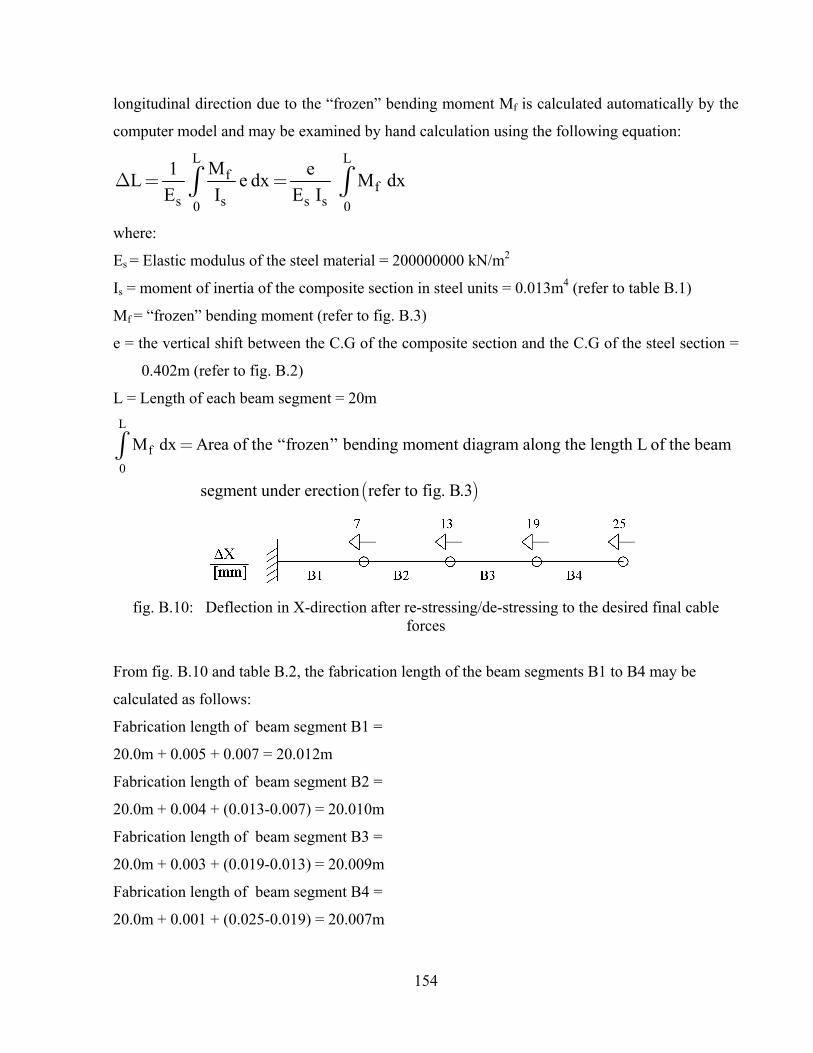
154
longitudinal direction due to the “frozen” bending moment Mf is calculated automatically by the
computer model and may be examined by hand calculation using the following equation:
L Lf
fs s s s0 0
M1 eL e dx M dx
E I E ID = =ò ò
where:
Es = Elastic modulus of the steel material = 200000000 kN/m2
Is = moment of inertia of the composite section in steel units = 0.013m4 (refer to table B.1)
Mf = “frozen” bending moment (refer to fig. B.3)
e = the vertical shift between the C.G of the composite section and the C.G of the steel section =
0.402m (refer to fig. B.2)
L = Length of each beam segment = 20m
( )
L
f
0
M dx Area of the “frozen” bending moment diagram along the length L of the beam
segment under erection refer to fig. B.3
=ò
fig. B.10: Deflection in X-direction after re-stressing/de-stressing to the desired final cable
forces
From fig. B.10 and table B.2, the fabrication length of the beam segments B1 to B4 may be
calculated as follows:
Fabrication length of beam segment B1 =
20.0m + 0.005 + 0.007 = 20.012m
Fabrication length of beam segment B2 =
20.0m + 0.004 + (0.013-0.007) = 20.010m
Fabrication length of beam segment B3 =
20.0m + 0.003 + (0.019-0.013) = 20.009m
Fabrication length of beam segment B4 =
20.0m + 0.001 + (0.025-0.019) = 20.007m

155
APPENDIX C
Application of the proposed construction method no. (5) on a cable-stayed bridge with a composite deck cross section (steel/concrete)
(refer to Section 4-3-4)
Software used: [SOFISTK 2012] & [Midas 2011]

156
fig. C.1: Geometrical data for the cable-stayed bridge with a composite deck (steel/concrete)
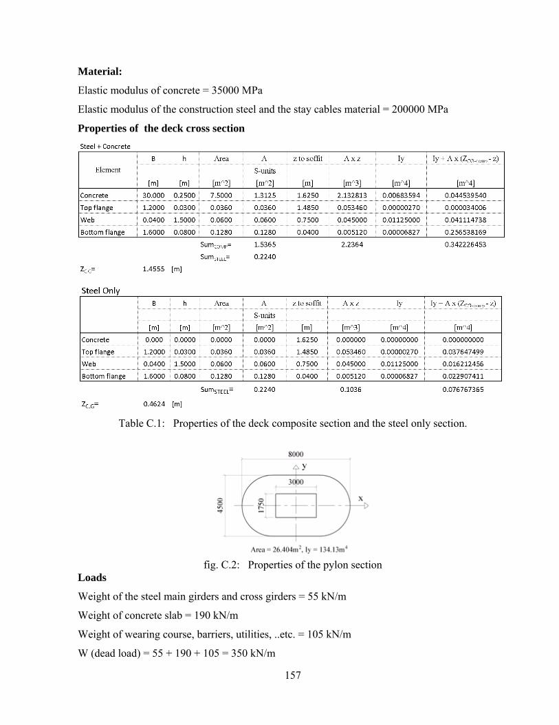
157
Material:
Elastic modulus of concrete = 35000 MPa
Elastic modulus of the construction steel and the stay cables material = 200000 MPa
Properties of the deck cross section
Table C.1: Properties of the deck composite section and the steel only section.
fig. C.2: Properties of the pylon section
Loads
Weight of the steel main girders and cross girders = 55 kN/m
Weight of concrete slab = 190 kN/m
Weight of wearing course, barriers, utilities, ..etc. = 105 kN/m
W (dead load) = 55 + 190 + 105 = 350 kN/m

158
Based on the above data and using the continuous beam method (Chapter 3/Section 3.1), the
desired cable forces at time infinity FDi are calculated (refer to table C.2). The first stage
installation forces F1 of the stay cables 11001 to 11009, 12001 to 12012, 13001 to 13012 and
14001 to 14009, are calculated by using equation (4.4) (refer also to fig. 4.7). The nos. of strands
are calculated based on the assumption that the cable forces due to live loads are equal to 50% of
the forces due to dead load. Further, the capacity of one strand under SLS is assumed equal to
115 kN. The data for cables 13001 to 13012 and 14001 to 140012 are similar to that of the cables
12001 to 12012 and 11001 to 11012 respectively.
Table C.2: Stay cables geometry, stressed lengthdesired cable forces for the completed structure at time infinity FDi, and the first stage installation forces F1
Notes:
Lui in table C.2 is the unstressed length of the stay cable and can be calculated from the following
formula:
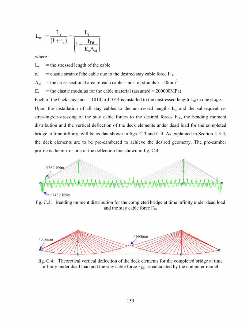
159
( )i i
uii Di
s si
L LL
1 F1
E A
= =æ ö+ e ÷ç ÷+ç ÷ç ÷çè ø
where :
Li = the stressed length of the cable
si = elastic strain of the cable due to the desired stay cable force FDi
Asi = the cross sectional area of each cable = nos. of strands x 150mm2
Es = the elastic modulus for the cable material (assumed = 200000MPa)
Each of the back stays nos. 11010 to 11014 is installed to the unstressed length Lui in one stage.
Upon the installation of all stay cables to the unstressed lengths Lui and the subsequent re-
stressing/de-stressing of the stay cable forces to the desired forces FDi, the bending moment
distribution and the vertical deflection of the deck elements under dead load for the completed
bridge at time infinity, will be as that shown in figs. C.3 and C.4. As explained in Section 4-3-4,
the deck elements are to be pre-cambered to achieve the desired geometry. The pre-camber
profile is the mirror line of the deflection line shown in fig. C.4.
fig. C.3: Bending moment distribution for the completed bridge at time infinity under dead load
and the stay cable force FDi
fig. C.4: Theoretical vertical deflection of the deck elements for the completed bridge at time
infinity under dead load and the stay cable force FDi, as calculated by the computer model

160
APPENDIX D
Application of the proposed construction method no. (5) on a cable-stayed bridge with a composite deck cross section (concrete/concrete)
(refer to Section 4-3-4)
Software used: [SOFISTK 2012] & [Midas 2011]

161
fig. D.1: Geometrical data for the cable-stayed bridge with a composite deck (concrete/concrete)

162
fig. D.2: Numbering system for stay cables
fig. D.3: Properties of the components of the composite deck section
fig. D.4: Properties of the pylon section
Material: Elastic modulus of concrete = 35000 MPa
Elastic modulus of the stay cables material = 200000 MPa
Loads
Weight of the spine segment (central part of the composite section) = 305 kN/m
Weight of the side frame segments = 190 kN/m
Weight of wearing course, barriers, utilities, ..etc. = 105 kN/m
W (dead load) = 305 + 190 + 105 = 600 kN/m

163
Based on the above data and using the continuous beam method (Chapter 3/ paragraph 3.1), the
desired stay cable forces at end of construction FDi are calculated (refer to table D.1). The first
stage installation forces F1 of the stay cables 11001 to 11009, 12001 to 12012, 13001 to 13012
and 14001 to 14009, are calculated by using equation (4.4) (refer also to fig. 4.7). The nos. of
strands are calculated based on the assumption that the cable forces due to live loads are equal to
50% of the forces due to dead load. Further, the capacity of one strand under SLS is assumed
equal to 115 kN. The data for cables 13001 to 13012 and 14001 to 140012 are similar to that of
the cables 12001 to 12012 and 11001 to 11012 respectively.
Table D.1: Stay cables geometry, desired cable forces for the completed bridge at time infinity
FDi, and first stage installation forces F1 Note:
Lui in table D.1 is calculated in the same way as that of table C.2 in Appendix C.
Each of the back stays nos. 11010 to 11014 is installed to the unstressed length Lui in one stage.

164
Upon the installation of all stay cables to the unstressed lengths Lui and the subsequent re-
stressing/de-stressing of the stay cable forces to the desired forces FDi, the bending moment
distribution and the vertical deflection of the deck elements under dead load for the completed
bridge, will be as that shown in figs. D.5 and D.6. As explained in Section 4-3-4, the deck
elements are to be pre-cambered to achieve the desired geometry. The pre-camber profile is the
mirror line of the deflection line shown in fig. D.6. It is also to be noted that the final vertical
deflection of the deck elements in this example is small when compared with the corresponding
vertical deflection in the example shown in Appendix C. This is attributed to the different value
of the ratio between the moment of inertia of the first part of the composite section Is to the
moment of inertia of the total composite section Icomp (refer to Section 4-3-3). The ratios Is / Icomp
in the examples of appendices C and D are equal to 23% and 69% respectively. Further the
vertical shift of the eccentricity “e” between the center of gravity of the first part of the composite
section and the center of gravity of the total composite section, are equal to 993mm in Appendix
C and 458mm in Appendix D. It is also to be noted that the time dependent effect (type II) has
been ignored in both of the examples in appendices C and D. This effect may be dealt with in the
same way as explained in Appendix B.
fig. D.5 Bending moment distribution for the completed bridge at time infinity under dead load
and the stay cable forces FDi
fig. D.6: Vertical deflection of the deck elements for the completed bridge at time infinity under
dead load and the sta cable forces FDi, as calculated by the computer model.

165
APPENDIX E
Stay cable forces under dead load for extradosed bridges
(refer to Chapter 6)
Software used: [SOFISTK 2012] & [Midas 2011]
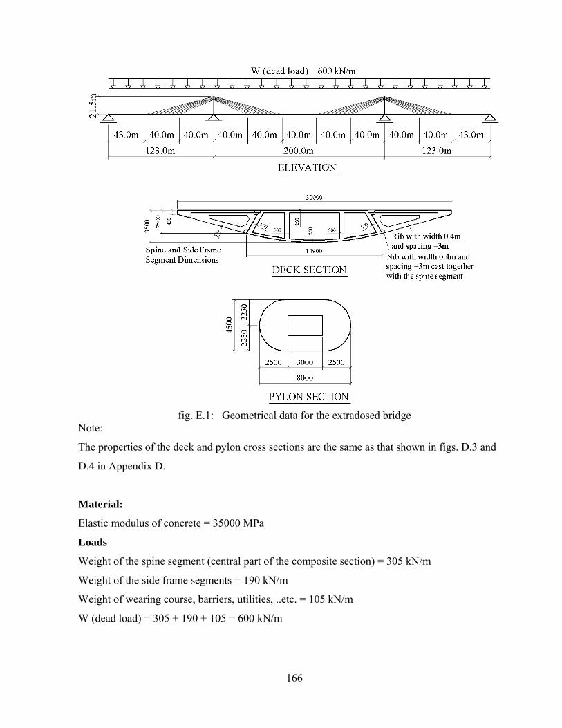
166
fig. E.1: Geometrical data for the extradosed bridge
Note:
The properties of the deck and pylon cross sections are the same as that shown in figs. D.3 and
D.4 in Appendix D.
Material:
Elastic modulus of concrete = 35000 MPa
Loads
Weight of the spine segment (central part of the composite section) = 305 kN/m
Weight of the side frame segments = 190 kN/m
Weight of wearing course, barriers, utilities, ..etc. = 105 kN/m
W (dead load) = 305 + 190 + 105 = 600 kN/m

167
Table E.1: Stay cables geometry, desired cable forces under dead load (the stay cables may be arranged in pair as shown in fig. 1.3) Note:
The desired stay cable forces under dead load FDi are calculated based on the assumption that the
equivalent uniform vertical load of the stay cable forces WC is equal to 1.9 W (refer to Chapter 6
and fig. 6.3). Accordingly, the sum of the vertical components of each 9-stay cables acting on
40m of the deck length = 1.9 x 600kN/m x 40m = 45600 kN. The vertical component of each stay
cable = 45600 / 9 = 5067kN and the desired stay cable force for cable no. 11005 (for example)
FD5 = 5067 x (62.642m / 18.0m) = 17633kN.
The cross sectional area of each stay cable (nos. of 150mm2 strands) is defined in the computer
model based on the assumption that the stay cable forces due to live loads are equal to 10% of the
stay cable forces due to dead loads. It is also assumed that the capacity of each strand under the
service load (dead + live load) = 115 kN.
Figs. E.2 and E.3 show the bending moment distribution and the stay cable forces due to the dead
load W (= 600 kN/m) before re-stressing the stay cables. By re-stressing the stay cables by the
forces Fi in accordance with equation 6.29 (in Chapter 6), the bending moment distribution
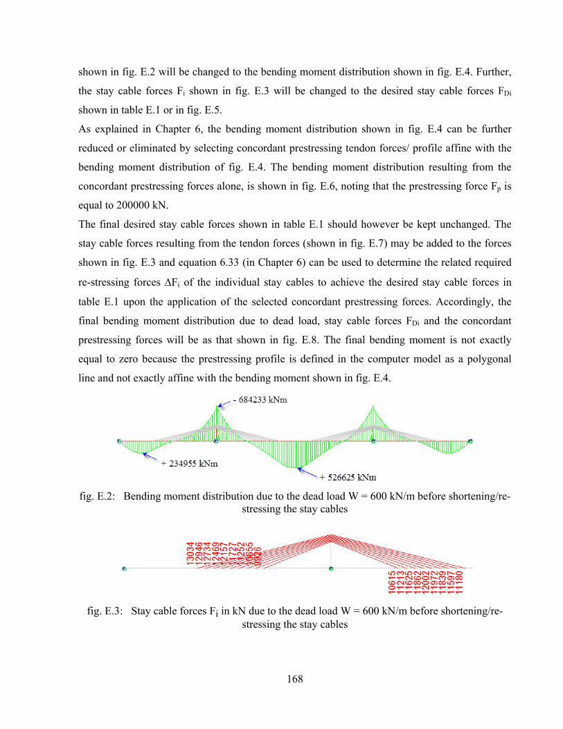
168
shown in fig. E.2 will be changed to the bending moment distribution shown in fig. E.4. Further,
the stay cable forces Fi shown in fig. E.3 will be changed to the desired stay cable forces FDi
shown in table E.1 or in fig. E.5.
As explained in Chapter 6, the bending moment distribution shown in fig. E.4 can be further
reduced or eliminated by selecting concordant prestressing tendon forces/ profile affine with the
bending moment distribution of fig. E.4. The bending moment distribution resulting from the
concordant prestressing forces alone, is shown in fig. E.6, noting that the prestressing force Fp is
equal to 200000 kN.
The final desired stay cable forces shown in table E.1 should however be kept unchanged. The
stay cable forces resulting from the tendon forces (shown in fig. E.7) may be added to the forces
shown in fig. E.3 and equation 6.33 (in Chapter 6) can be used to determine the related required
re-stressing forces Fi of the individual stay cables to achieve the desired stay cable forces in
table E.1 upon the application of the selected concordant prestressing forces. Accordingly, the
final bending moment distribution due to dead load, stay cable forces FDi and the concordant
prestressing forces will be as that shown in fig. E.8. The final bending moment is not exactly
equal to zero because the prestressing profile is defined in the computer model as a polygonal
line and not exactly affine with the bending moment shown in fig. E.4.
fig. E.2: Bending moment distribution due to the dead load W = 600 kN/m before shortening/re-stressing the stay cables
fig. E.3: Stay cable forces Fi in kN due to the dead load W = 600 kN/m before shortening/re-
stressing the stay cables

169
fig. E.4: Bending moment distribution due to the dead load W = 600 kN/m after shortening the stay cables (this diagram is used for the definition of the concordant prestressing cable profile)
fig. E.5: Desired Stay cable forces FDi in kN
fig. E.6: Bending moment distribution due to the “concordant” prestressing forces alone
(FP = 200000 kN)
fig. E.7: Stay cable forces due FPTi due to the prestressing forces alone

170
fig. E.8: Bending moment distribution due to the dead load W, the desired stay cable forces FDi
and the concordant prestressing forces
Note:
The next tables include the influence matrix for stay cable forces and the data used for solving the
equations (6.29) and (6.33) for the determination of the re-stressing forces Fi as described in
Chapter 6.

171

172
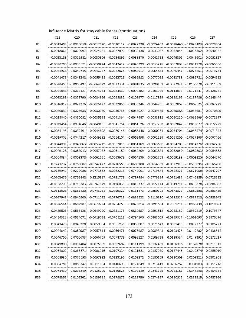
173

174
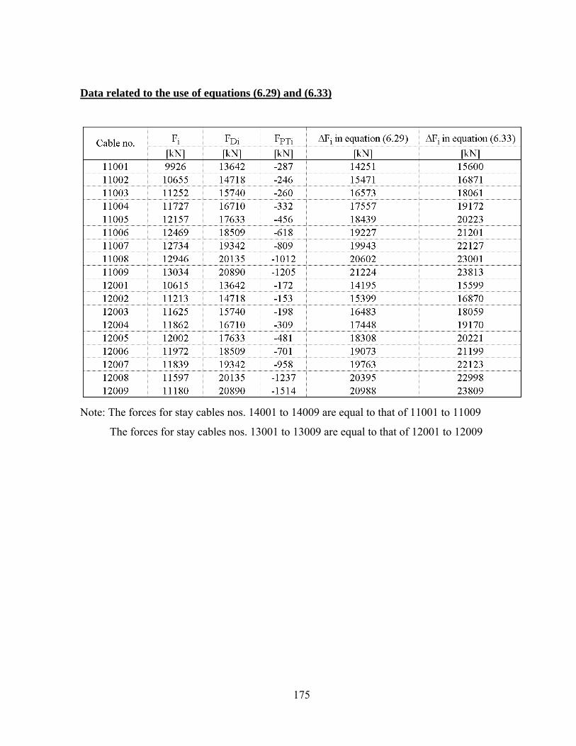
175
Data related to the use of equations (6.29) and (6.33)
Note: The forces for stay cables nos. 14001 to 14009 are equal to that of 11001 to 11009
The forces for stay cables nos. 13001 to 13009 are equal to that of 12001 to 12009