fronius ig plus 10-23-08
TRANSCRIPT

Fronius IG Plus3.0-1 / 3.8-1 / 5.0-1 / 6.0-1 / 7.5-110.0-1 / 11.4-1 / 11.4-3 / 12.0-3
42,0426,0071,EA 022008
Operating InstructionsUSA
Inverter for grid-connected photo-voltaic systems


ud_fr_st_et_01382 012008
Dear Fronius Customer,
Thank you for choosing Fronius - and congratulations on your new, high-quality, high-tech Fronius product. This introduction should provide you with general informationabout the equipment. Please read it carefully to learn about the many great features ofyour new Fronius product. This is the best way to get the most out of all the advantagesthat it has to offer.
Please also note the safety information and the safety precautions for the productinstallation location. Following all product instructions will ensure long-lasting quality andreliability. And these are the essential ingredients for outstanding results.
Introduction

ud_fr_st_et_01382 012008

IMPORTANT SAFETYINSTRUCTIONS
SAVE THESE INSTRUCTIONS
General This manual contains important instructions for the Fronius IG Plus, thatmust be followed during installation and maintenance of the inverter.
The Fronius IG Plus is designed and tested according to internationalsafety requirements, but as with all electrical and electronic equipment,certain precautions must be observed when installing and/or operating theFronius IG Plus.To reduce the risk of personal injury and to ensure the safe installationand operation of the Fronius IG Plus, you must carefully read and followall instructions and safety instructions in this manual.
Safety Instruc-tions
The following section “Safety Instructions“ contains different Warnings. AWarning describes a hazard to equipment or personnel. It calls attentionto a procedure or practice, which, if not correctly performed or adhered to,could result in damage to or destruction of part or all of the Fronius inver-ter and/or other equipment connected to the Fronius inverter or personalinjury.
All electrical installations must be made in accordance with the NationalElectrical Code, ANSI/NFPA 70, and any other codes and regulationsapplicable to the installation site.
For installations in Canada the installations must be done in accordancewith applicable Canadian standards.
Electricalinstallations

ud_fr_se_sv_01381 012008I
Safety Instructions
DANGER!
WARNING!
CAUTION!
“NOTE“ indicates a situation which could adversely affect work results andmay cause damage to equipment.
NOTE
This equipment has been manufactured using state-of-the-art technologyand in accordance with general safety regulations. However, incorrectoperation or misuse may endanger:- the life and well-being of the operator or third parties- the equipment and other property of the owner/operator- the efficient operation of the equipment.
All persons involved with equipment startup, service and maintenance must:- be suitably qualified- be familiar with electrical installations- have completely read and followed these operating instructions
The operating instructions must be available at the equipment location at alltimes. In addition to the operating instructions, all applicable local rules andregulations regarding accident prevention and environmental protection mustalso be followed.
General
Important
“DANGER!“ indicates an imminently hazardous situation which, if notavoided, will result in death or serious injury.
“WARNING!“ indicates a potentially hazardous situation which, if notavoided, will result in death or serious injury.
“CAUTION!“ indicates a potentially harmful situation which, if not avoided,may result in minor and moderate injury or property damage.
“Important“ indicates practical tips and other useful information. It is not asignal word for a harmful or dangerous situation.
Please pay special attention when one of the above symbols appears in themanual.

ud_fr_se_sv_01381 012008 II
The equipment may only be operated in compliance with its intended use.
Any other purpose does not constitute intended use. The manufacturer is notresponsible for any damages resulting from unintended use.
Intended use also includes:- reading and complying with all general information as well as safety
information and warnings from the operating instructions- compliance with all inspection and maintenance requirements- installation as per operating instructions
Where appropriate, the following guidelines should also be applied:- Utility company regulations regarding grid feed-in- Information from solar module manufacturer
Intended Use
All safety instructions and warning signs on the equipment itself:- must be maintained in legible condition- must not be damaged- must not be removed- must not be covered or painted over
For information about where the safety instructions and warning signs arelocated on the equipment, please refer to the “General“ section of yourequipment’s operating instructions.
Any equipment malfunctions which might impair safety must be remediedimmediately before the device is turned on.
Your safety is at stake.
General(continued)
Operation and/or storage of the device outside of the stipulated range doesnot constitute intended use. The manufacturer is not responsible for anydamages resulting from unintended use.
Please refer to the technical data in your operating instructions for informati-on about permitted ambient conditions.
Ambient Conditi-ons
Qualified Person-nel
The service information in these operating instructions is only intended forqualified personnel. An electrical shock can be fatal. Please do not carry outany activities other than those referred to in the documentation even if youare suitably qualified.
All cables and wires must be secured, undamaged, insulated and adequatelydimensioned. Loose connections, scorched, damaged or under-dimensionedcables and wires must be repaired immediately by an authorized specialist.

ud_fr_se_sv_01381 012008III
Maintenance and repair may only be carried out by an authorized specialist.
The use of third-party parts does not guarantee that they were designed andmanufactured according to operational demands and safety requirements.Use only original spare parts (also applies to standard parts).
Do not carry out any alterations, installations or modifications to the devicewithout first obtaining the manufacturer’s permission.
Immediately replace any components that are not in perfect condition.
Qualified Person-nel(continued)
Safety Precauti-ons at EquipmentLocation
When installing devices with air vents, make sure that cool air can flow freely through thevents unobstructed. The device should only be operated in accordance with the protec-tion class listed on the rating plate.
Care must be taken during installation to ensure that there is no electromag-netic interference with electrical and electronic equipment.
EMC Precautions
Danger of damage to electronic components due to electrostatic discharge.Take appropriate ESD precautions when replacing and installing compon-ents.
ESD Precautions
Electrical Installa-tions
Electrical installations may only be carried out in accordance with relevantnational and local standards and regulations.
The device should only be operated when all safety equipment is fully func-tional. If safety equipment is not fully functional, there is a danger to:- the life and well-being of the operator or third parties- the equipment and other property of the owner/operator- the efficient operation of the equipment
Safety equipment that is not fully functional must be repaired by an authori-zed specialist before the device is turned on.
Never bypass or disable safety equipment.
Safety Precauti-ons in Normal-Operation

ud_fr_se_sv_01381 012008 IV
Equipment with the CE marking fulfils the basic requirements of the Guideli-ne Governing Low-Voltage and Electromagnetic Compatibility. (For moreinformation, please see the attachment and/or the “Technical Data“ section inyour documentation).
Safety Markings
The user is responsible for backing up data relating to changes made tofactory settings. The manufacturer will not accept liability if personal settingsare deleted.
Data Security
The manufacturer maintains the copyright to these operating instructions.
Text and illustrations are technically correct at the time of going to print. Theright to make modifications is reserved. The contents of the operating in-structions shall not provide the basis for any claims whatsoever on the partof the purchaser. We would be grateful for any comments or suggestionsregarding improvements and/or error corrections for the operating instruc-tions.
Copyright
This device should not be disposed of in residential waste.To comply with European Directive 2002/96/EC on Waste Electrical andElectronic Equipment and its implementation as national law, electricalequipment that has reached the end of its life must be collected separatelyand returned to an approved recycling facility. Any device that you no longerrequire must be returned to your dealer or you must find an approved collec-tion and recycling facility in your area.Ignoring this EU Directive may have adverse affects on the environment andyour health.
Disposal

1
Table of Contents
General Information 7
Protection of persons and equipment ................................................................................ 9Safety............................................................................................................................. 9Protection of persons and equipment ............................................................................ 9Galvanic isolation ........................................................................................................... 9Monitoring the grid ......................................................................................................... 9Information for Field adjustable trip points ................................................................... 10FCC Compliance ......................................................................................................... 10Ground Fault Detector / Interruptor .............................................................................. 10Standards and Regulations .......................................................................................... 10Product listings and compliance .................................................................................. 10
The Fronius IG Plus Unit in the PV System ...................................................................... 11General information ...................................................................................................... 11Tasks............................................................................................................................. 11Converting DC into AC current...................................................................................... 11Fully automatic operation management ........................................................................ 11Display function and data communication ................................................................... 12System Upgrades ........................................................................................................ 12Forced ventilation ........................................................................................................ 12Power Derating ............................................................................................................ 13
Operation 15
Product description Fronius IG Plus................................................................................. 17Keys and Symbols ....................................................................................................... 17Display ......................................................................................................................... 17Test Procedure............................................................................................................. 19Startup phase............................................................................................................... 19Operating Status LED .................................................................................................. 21
Operating scheme - the Display ....................................................................................... 23Activating ..................................................................................................................... 23Display Illumination ...................................................................................................... 23Accessing Menus ......................................................................................................... 23Selecting a display mode ............................................................................................. 24Scrolling Between Display functions ............................................................................ 24Overview of Display Values ......................................................................................... 25
Display Modes ................................................................................................................. 26Display Modes ............................................................................................................. 26Overview ...................................................................................................................... 26
Within display mode ‘Now’ displayed data ....................................................................... 27Selecting display mode ‘Now’ ...................................................................................... 27Within display mode ‘Now’ displayed data ................................................................... 27Options ........................................................................................................................ 29

2
Within display modes ‘Day / Year / Total’ displayed data ................................................. 30General ........................................................................................................................ 30Selecting display modes ‘Day / Year / Total’ ................................................................. 30Within display modes ‘Day / Year / Total’ displayed data ............................................. 31Options ........................................................................................................................ 33
The Setup Menu .............................................................................................................. 34Default Settings ........................................................................................................... 34Enter the setup menu .................................................................................................. 34Scrolling among menu items ....................................................................................... 35Menu Items in the Setup Menu .................................................................................... 35
Setting and Displaying Menu Items.................................................................................. 38Menu Items Settings - General .................................................................................... 38Setting Menu Item ‘STANDBY’ ...................................................................................... 38Setting menu item ‘CONTRAST’ ................................................................................... 39Setting menu item ‘LIGHTMODE’ ................................................................................... 39Setting menu item ‘CASH’ ........................................................................................... 40Setting menu item ‘CO2’ .............................................................................................. 42Setting menu item ‘YIELD’ ........................................................................................... 43Setting menu item ‘IG NO.’ ............................................................................................ 46Setting menu item ‘DATCOM’ ........................................................................................ 47Setting menu item ‘TIME’............................................................................................. 48Displaying menu item ‘STATEPS’ ................................................................................. 51Displaying menu item ‘VERSION’ ................................................................................. 52
Installation and Startup 57
Fronius IG Plus Installation and Connection .................................................................... 59Safety........................................................................................................................... 59Fronius IG Plus Construction ....................................................................................... 59Connection Diagramm ................................................................................................. 60Overview ...................................................................................................................... 60
Fronius IG Plus Connection Options ................................................................................ 61Fronius IG Plus Connection Options ........................................................................... 61
Knockouts on the Fronius IG Plus.................................................................................... 63General ........................................................................................................................ 63Knockouts for Wire Inputs............................................................................................ 63
Choosing the Location ..................................................................................................... 65Choosing the location general ..................................................................................... 65Choosing a Location for Inside Installation .................................................................. 65Choosing a Location for Outside Installation ............................................................... 66
Fronius IG Plus Installation .............................................................................................. 67General ........................................................................................................................ 67Assembling the Wall Bracket ....................................................................................... 67Recommended Screws for Wall Bracket Assembly ..................................................... 67Attaching the Wall Bracket - Mounting height .............................................................. 67Attaching the Wall Bracket to a Concrete or Brick Wall ............................................... 68Attaching the Wall Bracket to a Wooden Wall ............................................................. 68Attaching the Wall Bracket to a Metal Carrier .............................................................. 69Fronius IG Plus Installation .......................................................................................... 69Installation of Several Inverters.................................................................................... 70

3
Connecting the Fronius IG Plus to the Public Grid (AC) .................................................. 71Overview of Available Power Grids .............................................................................. 71Monitoring the Grid ...................................................................................................... 73Schemes with more than one inverter ......................................................................... 73AC-side Terminals ........................................................................................................ 74Cross Section of AC Wires .......................................................................................... 75Safety........................................................................................................................... 75Connecting the Fronius IG Plus to the Public Grid (AC) .............................................. 76Recommendation for the AC-side over current protection ........................................... 77
Connecting Solar Module Strings to the Fronius IG Plus (DC) ........................................ 78General Information About Solar Modules ................................................................... 78Safety........................................................................................................................... 78DC-Terminals ............................................................................................................... 79Overview ...................................................................................................................... 79
Connecting Solar Module Strings ..................................................................................... 80Solar Module Ground................................................................................................... 80Wire Cross Section of Solar Module Strings ................................................................ 80Connecting Solar Module Strings ................................................................................ 81Connecting Grounding Electrode Wire ........................................................................ 83Inserting String fuses into the Fronius IG Plus ............................................................. 83
Criteria for the Proper Selection of String Fuses .............................................................. 85DC disconnect requirements........................................................................................ 85General ........................................................................................................................ 85Criteria for the Proper Selection of String Fuses ......................................................... 85Effects of using underrated fuses ................................................................................ 85Fuse Recommendations - Application Example .......................................................... 86Fuses ........................................................................................................................... 86
Solar Module Ground at Positive Pole: Connecting Solar Module Strings ....................... 87General ........................................................................................................................ 87Wire Cross Section of Solar Module Strings ................................................................ 87Solar Module Ground at Positive Pole ......................................................................... 87Solar Module Ground at Positive Pole: Connecting Solar Module Strings ................... 88Connecting Grounding Electrode Wire ........................................................................ 91Solar Module Ground at Positive Pole: Inserting String fuses into the Fronius IG Plus 91
Criteria for the Proper Selection of String Fuses .............................................................. 93DC disconnect requirements........................................................................................ 93General ........................................................................................................................ 93Criteria for the Proper Selection of String Fuses ......................................................... 93Effects of using underrated fuses ................................................................................ 93Fuse Recommendations - Application Example .......................................................... 94Fuses ........................................................................................................................... 94
Attaching Power Stage Sets and Closing the Fronius IG Plus ......................................... 95Preparation .................................................................................................................. 95Opening the Fronius IG Plus for Service/Maintenance ................................................ 95Attaching Power Stage Sets And Closing the Fronius IG Plus..................................... 95
Start up Operation ............................................................................................................ 96Factory pre-set configuration ....................................................................................... 96Requirements for Starting up Operation ...................................................................... 96Start up Operation........................................................................................................ 96Selecting the public grid ............................................................................................... 97Startup Phase at Startup Operation ............................................................................. 99

4
Inserting Option Cards ................................................................................................... 101Suitable Option Cards ................................................................................................ 101Safety......................................................................................................................... 101Opening the Fronius IG Plus ..................................................................................... 101Inserting Option Cards ............................................................................................... 102Connecting Option Cards, Laying Data Communication Wires ................................. 102Solar Net and Data Interface ..................................................................................... 104Closing the Fronius IG Plus ....................................................................................... 104Example ..................................................................................................................... 105
Troubleshooting and Maintenance 107
Status Diagnosis and Troubleshooting ........................................................................... 109Displaying Status Codes ........................................................................................... 109Normal operation status codes .................................................................................. 109Total failure ................................................................................................................ 109Status Codes on Fronius IG Plus with several power stage sets ................................ 110Class 1 Status Codes ................................................................................................. 110Class 2 Status Codes ................................................................................................. 112Class 3 Status Codes ................................................................................................. 113Class 4 Status Codes ................................................................................................. 115Class 5 Status Codes ................................................................................................ 122Customer Service ...................................................................................................... 124
Maintenance .................................................................................................................. 125Safety......................................................................................................................... 125General ...................................................................................................................... 125Operation in Dusty Environments .............................................................................. 126Opening Fronius IG Plus for Service/Maintenance .................................................... 126
Replacing String Fuses .................................................................................................. 127Safety......................................................................................................................... 127Preparation ................................................................................................................ 127Replacing String Fuses .............................................................................................. 128Closing Fronius IG Plus ............................................................................................. 129
Replacing GFDI Fuse..................................................................................................... 130Safety......................................................................................................................... 130Preparation ................................................................................................................ 130Replacing GFDI Fuse ................................................................................................ 131Closing Fronius IG Plus ............................................................................................. 132
Appendix 133
Technical Data ............................................................................................................... 135Fronius IG Plus 3.0-1 ................................................................................................. 135Fronius IG Plus 3.8-1 ................................................................................................. 137Fronius IG Plus 5.0-1 ................................................................................................. 139Fronius IG Plus 6.0-1 ................................................................................................. 141Fronius IG Plus 7.5-1 ................................................................................................. 143Fronius IG Plus 10.0-1 ............................................................................................... 145Fronius IG Plus 11.4-1 ............................................................................................... 147Fronius IG Plus 11.4-3 ............................................................................................... 149Fronius IG Plus 12.0-3 ............................................................................................... 151Field adjustable trip points ......................................................................................... 153

5
Relevant Standards and Directives ................................................................................ 154Relevant Standards and Directives ............................................................................ 154Grid Failure ................................................................................................................ 154
Warranty and Disposal ................................................................................................... 155FRONIUS USA limited 10-Year Warranty .................................................................. 155Policy and procedure for warranty returns and repairs .............................................. 155Disposal of obsolete equipment - Recycling .............................................................. 156

6

7
General Information

8

9
Safety
Protection of persons and equipment
WARNING! Incorrect operation and work performed incorrectlycan cause serious injury & damage! Only qualified staff areauthorized to install your Fronius IG Plus and only within thescope of the respective technical regulations. Do not startoperation or carry out maintenance work before you have readthe chapter ‘Safety Instructions’!
The design and function of the Fronius IG Plus unit offers a maximumlevel of safety, both during installation as well as in operation.
The Fronius IG Plus provides operator and equipment protection through:a) galvanic isolationb) monitoring the grid
Protection ofpersons andequipment
Galvanic isola-tion
The Fronius IG Plus is equipped with a high frequency transformer thatensures galvanic isolation between the DC side and the grid, thus ensu-ring the highest possible safety.
Whenever conditions in the electric grid are inconsistent with standardconditions (for example grid switch-off, interruption, etc.), your Fronius IGPlus unit will immediately stop operating and interrupt the supply of powerinto the grid.
Monitoring thegrid
WARNING! An electrical shock can be fatal. Danger from gridvoltage and DC voltage from solar modules.- The connection area should only be opened by a licensed
electrician.- The separate power stage set area should only be discon-
nected from the connection area after first being discon-nected from the grid power.
- The separate power stage set area should only be openedby Fronius-trained service personnel.
Never work with live wires! Prior to all connection work, makesure that the AC and DC wires are not charged.

10
FCC Compli-ance
This device complies with Part 15 of the FCC Rules. Operationis subject to the following conditions:(1) This device may not cause harmful interference, and(2) this device must accept any interference received, includinginterference that may cause undesired operation.
Ground FaultDetector /Interruptor
Your Fronius IG Plus unit complies with the requirements for the followingstandards "Inverters, converters and controllers for use in independentpower systems":- UL1741-2005- IEEE 1547-2003- IEEE 1547.1- ANSI / IEEE C62.41- C22.2 No. 107.1-01 (Sep. 2001)
The ground-fault detection and interruption is in compliance with NEC 690building code requirements.
The respective conformity declarations can be found in the appendix tothese operating instructions.
Standards andRegulations
Product lis-tings andcompliance
The Fronius IG Plus unit is provided with field adjustable trip points. Forfurther information please contact Fronius technical support E-Mail: [email protected].
Informationfor Field adju-stable trippoints
Monitoring thegrid(continued)
Your Fronius IG Plus unit determines the grid’s status by:- monitoring voltage- monitoring frequency- monitoring islanding conditions
The Fronius IG Plus is equipped with a ground fault detection and inter-ruption (GFDI) circuit as required by UL 1741 and the National Electricalcode.Depending on the system configuration either the PV array’s negative orpositive conductor is connected to the grounding system in the inverter. Ifa ground fault occurs in the DC wiring, the inverter disconnects from thegrid.

11
The solar inverter Fronius IG Plus is the highly complex link between solarmodules and the grid.
General infor-mation
The Fronius IG Plus Unit in the PV System
The Fronius IG Plus unit transforms the direct current generated by thesolar modules into alternating current. This alternating current is fed intoyour home system or into the public grid and synchronized with the volta-ge that is used there.
Important The Fronius IG Plus has been designed exclusively for usein grid connected photovoltaic systems. It cannot generate electric powerindependent from the grid.
Converting DCinto AC cur-rent
The Fronius IG Plus is fully automatic. Starting at sunrise, as soon as thesolar modules generate enough power, the automatic control unit startsmonitoring voltage and frequency. As soon as there is a sufficient level ofirradiance, your solar inverter starts feeding energy to the grid.
The control system of the Fronius IG Plus unit ensures that the maximumpossible power output is drawn from the solar modules at all times.This function is called MPPT (Maximum Power Point Tracking).
Fully automa-tic operationmanagement
Tasks The main tasks of the Fronius IG Plus include:- Converting DC into AC current- Fully automatic operation management- Display function and data communication
PV array
Fronius IG Plus
Main ACLoadCenter
Energy-meter

12
Fully automa-tic operationmanagement(continued)
As dusk starts and there is no longer sufficient energy available to feedpower into the grid, the Fronius IG Plus unit shuts down the grid connec-tion completely and stops operating. All settings and data recorded aresaved.
The display on the inverter is the interface between the inverter and theoperator. The design of the display is geared towards simple operationand making system data available as long as the inverter operates.
The Fronius IG Plus is equipped with a basic logging function to monitorminimum and maximum data on a daily and a cumulative basis. Thesevalues are shown on the display.
There is also an option to allow the reading of the following weather dataon the display:- two different temperature readings (for example, temperature at the
solar modules as well as the outside temperature)- irradiance
A wide choice of data communication products allows for many possibili-ties of recording and viewing data.
Display func-tion and datacommunicati-on
The Fronius IG Plus is designed for various system upgrades, e.g.:- Upgrades that enable Fronius IG Plus to communicate with external
system upgrades as well as other inverters- Datalogger and modem interface, Ethernet/Internet connection (for
using a PC to record and manage data from your photovoltaic system)- Various large-format displays- Living room display (Fronius Personal Display)- Sensors (e.g. for temperature, irradiance, energy meter, wind speed)- Interface cards
System upgrades are available as plug-in cards or external boxes.
System Up-grades
Forced venti-lation
The temperature controlled, variable speed fan with ball bearing supportof the Fronius IG Plus provides:- optimal inverter cooling- efficiency increases- cooler components, thus improving service life- least possible energy consumption and noise level

13
Should there be insufficient heat dissipation in spite of the fan operating atmaximum speed (for example inadequate heat transfer away from theheat sinks) the power will be derated for protection of the Fronius IG Plusunit.
Derating the power reduces the output of the Fronius IG Plus unit for ashort period sufficient to ensure that the temperature will not exceed theadmissible limit.Your Fronius IG Plus unit will remain ready for operation as long as pos-sible without any interruption.
Power Dera-ting

14

15
Operation

16

17
Product description Fronius IG Plus
Keys andSymbols
(1) (2)
(3)(4)(5)(6)
Keys and Symbols on the Fronius IG Plus
Display Power for the display comes from the solar modules via safety-low volta-ge. The display is, therefore, available only during daylight hours.
Important The Fronius IG Plus display is not a calibrated measuringinstrument. A slight deviation of a few percent points is intrinsic to thesystem. A calibrated meter is required to make calculations for the utilitycompany.
Item Function(1) Display
for displaying values, settings and menus(2) Operating Status LED
for displaying the operating status(3) ‘Enter’ key
for confirming a choice(4) ‘Menu / Esc’ key
switching to the menu level (‘Menu’) or exit from the setup menu(‘Esc’)
(5) ‘Down/Right’ keydepending on the selection:for navigating downfor navigating right
(6) ‘Left/Up’ keydepending on the selection:for navigating leftfor navigating up

18
Display(continued)
(12)
(1) (2) (3) (4) (5)
(6)
(7)
(8)(9)(10)(11)
(13)
Display
... indicates the maximum value within the period of obser-vation (depending on the display mode chosen)
... indicates the minimum value within the period of obser-vation (depending on the mode of display chosen)
Important The Min. and Max. values may not corres-pond to the absolute extreme values, as the measureddata are recorded at two second intervals.
... appears with data readings that are transmitted by theenergy meter (optional)
... appears with data readings that are directly related tothe solar modules
... appears with data readings that are related to environ-mental conditions, like solar irradiance and temperature(optional)
... appears with AC data readings that are directly relatedto the grid
... appears with data readings that are related directly tothe Fronius IG Plus unit
Item Function(1) Icons for the ‘Now’ display mode(2) Icons for the ‘Day’ display mode(3) Icons for the ‘Year’ display mode(4) Icons for the ‘Total’ display mode(5) Icons for the ‘Setup’ display mode(6) Icons for operating conditions

19
Item Function(7) area for unit display
for displaying the applicable measuring unit(8) Icon for the ‘Enter’ key(9) Icons for the ‘Menu/Esc’ key(10) Icons for the ‘Down/Right’ key(11) Icons for the ‘Left/Up’ key(12) Area for data
for displaying the data value measured(13) output bar (not active during setup)
indicates the power output fed into the grid at a given moment -independent from the display mode chosen. The screen displays% of the maximum possible output power of your solar inverter
Startup phase After switching on automatically, the Fronius IG Plus unit goes through aself-test, followed by an extensive test of the grid. This test takes fiveminutes. During the startup sequence the illumination of the OperatingStatus LED is yellow.
1. Segment testAll display elements light up for about one second
2. Self test of important components of the Fronius IG Plus unit- The Fronius IG Plus unit goes through a master check list for
several seconds- The display shows ‘TEST’ and indicates the respective component
which is being tested (for example ‘LED’)
3. Synchronization with grid- ‘WAITPS’ is shown: The Fronius IG Plus is waiting for all power
stage sets in the network to be on stand-by. This procedure takesplace dependent on the DC-voltage.
Test Procedu-re
Display(continued)

20
Test Procedu-re(continued)
- Next, the display shows ‘SYNCAC’, the grid icon blinks
4. Startup Test- Before the Fronius IG Plus unit starts feeding energy into the grid,
the conditions of the grid are tested in detail in accordance withregulations.
- The display shows ‘STARTUP’
The startup test takes five minutes. The time elapsed is indicated by abar shrinking from the top down.
Whenever two scale divisions stop flashing and disappear, 1/10 of thetotal duration of the test is over.
5. Operation of feeding energy into the grid- After conclusion of the tests, the Fronius IG Plus unit starts fee-
ding energy into the grid.- The display shows the present power feeding into the grid- The Operating Status LED lights up green, and the Fronius IG
Plus unit starts operating
21
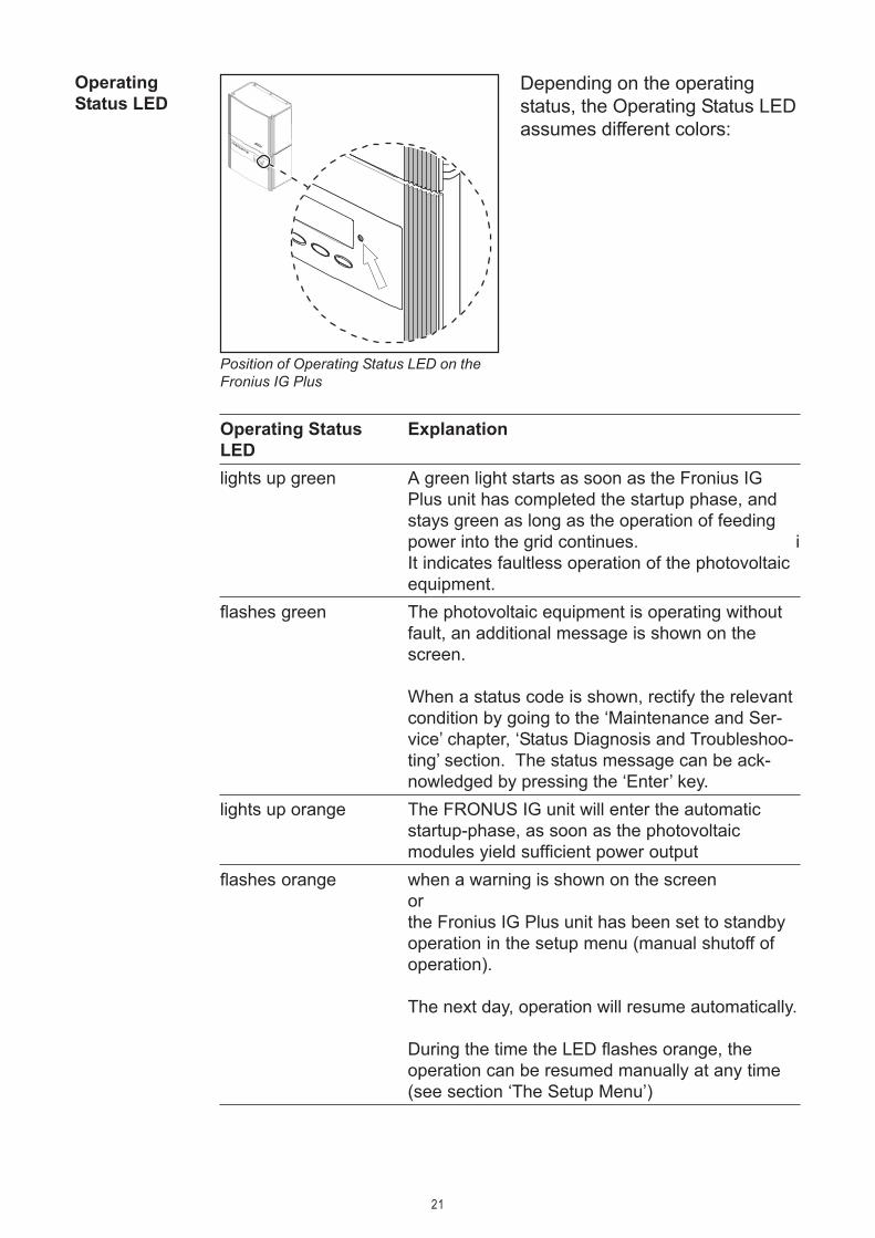
OperatingStatus LED
Operating Status ExplanationLEDlights up green A green light starts as soon as the Fronius IG
Plus unit has completed the startup phase, andstays green as long as the operation of feedingpower into the grid continues. iIt indicates faultless operation of the photovoltaicequipment.
flashes green The photovoltaic equipment is operating withoutfault, an additional message is shown on thescreen.
When a status code is shown, rectify the relevantcondition by going to the ‘Maintenance and Ser-vice’ chapter, ‘Status Diagnosis and Troubleshoo-ting’ section. The status message can be ack-nowledged by pressing the ‘Enter’ key.
lights up orange The FRONUS IG unit will enter the automaticstartup-phase, as soon as the photovoltaicmodules yield sufficient power output
flashes orange when a warning is shown on the screenorthe Fronius IG Plus unit has been set to standbyoperation in the setup menu (manual shutoff ofoperation).
The next day, operation will resume automatically.
During the time the LED flashes orange, theoperation can be resumed manually at any time(see section ‘The Setup Menu’)
Position of Operating Status LED on theFronius IG Plus
Depending on the operatingstatus, the Operating Status LEDassumes different colors:

22
OperatingStatus LED(continued)
Operating Status ExplanationLEDlights up red General status: the respective status code is
shown on the screenremains dark There is no connection to the solar modules;
no power output from modules due to darkness
A list of most status codes, the corresponding status information, theirstatus causes and repair measures can be found in the chapter ‘Trouble-shooting and Maintenance’, section ‘Status Diagnosis and Troubleshoo-ting’.

23
1. Press any key
The display backlight is activated.
If no key is pressed for 30 seconds, the display backlight stops.The setup menu also offers a choice between permanently lit or per-manently dark display.
ActivatingDisplay Illumi-nation
Operating scheme - the Display
AccessingMenus
(1)
1. Press the ‘Menu’ button (1)
Accessing Menus
‘Menu’ will appear on the dis-play
The Fronius IG Plus is now inthe menu level.
From the menu level you can- set the desired display mode- access the Setup menu
Menu Levels

24
(1) (2) (3) (4)
(5)(6)(7)
(2)(1) (2)(1)
Selecting adisplay mode
1. Accessing Menu Levels2. Use the ‘left (7) or ‘right’ (6)
keys to select your preferreddisplay mode (1) - (4)
3. Press ‘Enter’ (5)
Selecting a Display Mode
The selected display mode isshown
Important The ‘Year’ menu optionis supported only when the optionalDatalogger is connected. Thissystem upgrade includes a real-time clock.
Example: ‘Day’ display mode
ScrollingBetween Dis-play functions
1. Selecting a desired display mode2. Scroll through the available display values using the ‘Up’ (1) and
‘Down’ (2) keys
Example: ‘Fed-in Energy’ display value Example: ‘Earnings’ display value

25
Display Icon Unit Optional Display valuemode‘Now’ W - output power
V - grid voltageA - output currentHz - grid frequencyV - module voltageA - module current
°F / °C x module temperature- - GFDI status
W x output reading of building loadmeter
° F / ° C x ambient temperatureW/m² x irradiance
HH:MM x time‘Day’ kWh / MWh - energy supplied
currency - yieldkg / T - CO2 reduction
W - maximum power outputV - maximum grid voltageV - minimum grid voltageV - maximum array voltage
kwh / MWh x energy as read by building loadmeter
° F / ° C x maximum module temperature° F / ° C x minimum module temperature° F / ° C x maximum ambient temperature° F / ° C x minimum ambient temperatureW/m² x maximum irradiance
HH:MM - operating hours of Fronius IGPlus unit
x optionalWhen the DatCom component for the required option is not available,the message ‘N.A.’ (not available) is shown.
Overview ofDisplay Values
‘Year’‘Total’

26
Display Modes
The following display modes are available for the Fronius IG Plus:
Display mode ‘Now’ ..........shows present data
Display mode ‘Day’...........shows data for the present day
Display mode ‘Year’ ..........shows data for present calendar year - onlyavailable in combination with optional Datalog-ger
Display mode ‘Total’ .........shows data since your Fronius IG Plus unit firststarted operating
Display Modes
Overview The ‘display modes’ are composed of the following sections:- Within display mode ‘Now’ displayed data- Within display modes ‘Day / Year / Total’ displayed data

27
(1) (2)
Within display mode ‘Now’ displayed data
AC power suppliedpower supplied to grid at the parti-cular moment (Watts)
AC grid voltage(Volts)
Within displaymode ‘Now’displayed data
Grid frequency(Hertz)
AC current suppliedcurrent supplied to the grid at theparticular moment (Amperes)
*)
*)
*) only for a multi-phase Fronius IG Plus
Selectingdisplay mode‘Now’
1. Select display mode ‘Now’
The first display value appearsin the ‘Now’ display mode
2. Use the ‘Down’ (2) key to scrollto the next display value
Scroll back using the ‘Up’ key(1)
First display values in the ‘Now’ displaymode

28
Within displaymode ‘Now’displayed data(continued)
DC array voltagevoltage of the solar array at themoment of data display (Volts)
DC array currentcurrent supplied by solar array atthe moment of data display(Amperes)
The voltage shown while AC power is supplied is called MPP voltage(MPP = maximum power point).
Module temperature (optional)temperature at solar modules (°F;can also be set for °C; this corres-ponds to temperature sensor No.1;Sensor Box, Datalogger and tem-perature sensor required)
GFDI-Statusif there is no ground fault in thesystem, ‘OK GFDI’ is shown
Power drawn from the grid (opti-onal)present consumption (Watts; Sen-sor Box, Datalogger and load sen-sor required)
Ambient temperature (optional)(° F; can also be set for ° C insetup menu; this corresponds totemperature sensor No.2; SensorBox, Datalogger and temperaturesensor required)
Irradiance (optional)the sunlight’s power per squaremeter (Watts/m²; Sensor Box andirradiance sensor required)
NL-MON CommunicationWhen the communication with theplug-in card ‘NL-MON’ sustains‘NLMONOK’ is shown.

29
Options If the DatCom component for the required options are not available, themessage "N.A." (not available) is shown.
Time of the day (optional data-logger)When the time on the Fronius IGPlus or a system upgrade is chan-ged, this changes the time on allconnected devices via Solar Net.
Within displaymode ‘Now’displayed data(continued)
30
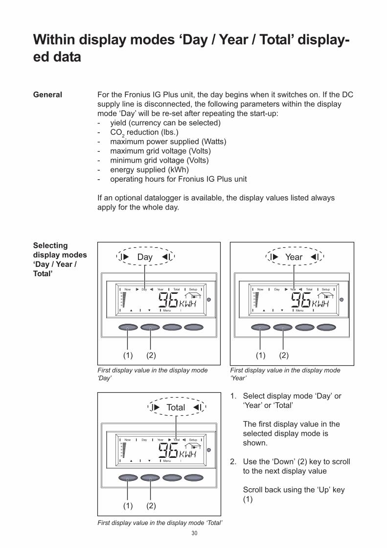
1. Select display mode ‘Day’ or‘Year’ or ‘Total’
The first display value in theselected display mode isshown.
2. Use the ‘Down’ (2) key to scrollto the next display value
Scroll back using the ‘Up’ key(1)
(1) (2) (1) (2)
For the Fronius IG Plus unit, the day begins when it switches on. If the DCsupply line is disconnected, the following parameters within the displaymode ‘Day’ will be re-set after repeating the start-up:- yield (currency can be selected)- CO2 reduction (lbs.)- maximum power supplied (Watts)- maximum grid voltage (Volts)- minimum grid voltage (Volts)- energy supplied (kWh)- operating hours for Fronius IG Plus unit
If an optional datalogger is available, the display values listed alwaysapply for the whole day.
Within display modes ‘Day / Year / Total’ display-ed data
General
Selectingdisplay modes‘Day / Year /Total’
(1) (2)
First display value in the display mode‘Day’
First display value in the display mode‘Year’
First display value in the display mode ‘Total’

31
Within displaymodes ‘Day /Year / Total’displayed data
Energy suppliedenergy supplied during monitoredperiod (kWh / MWh)
Due to the variety of different monitoring systems, there can be deviationsbetween the readings of other metering instruments as compared to thereadings from the Fronius IG Plus. For determining the energy supplied tothe grid, only the readings of the calibrated meter supplied by the electricutility company are relevant.
Yieldmoney earned during monitoredperiod (set currency and price perkWh in setup menu)
As was the case for the energy supplied, readings may differ from thoseof other instruments.
CO2 reductionCO2 emissions avoided during monitored period (lb / T); T = tonsThe area for unit display switches between ‘lb’ and ‘CO2’.
The CO2 meter gives an indication of CO2 emissions (in lb/t) that would bereleased during the generation of the same amount of electricity in acombustion power plant.This is set for 1.3 lb/kWh in the factory.
Maximum output powerhighest output power of the FroniusIG Plus during observation period(Watts)
Maximum grid voltagehighest reading of grid voltage (V)during observation period
Minimum grid voltagelowest reading of grid voltage (V)during observation period

32
Minimum ambient temperature(optional)lowest ambient temperature rea-ding during observation period (°F;can also be set for °C in setupmenu; temperature sensor No 2,Datalogger and Sensor Box re-quired)
Within displaymodes ‘Day /Year / Total’displayed data(continued)
Maximum array voltagehighest reading of array voltage (V)during observation period
Energy consumption meter rea-ding (optional)energy consumed during observati-on period (kWh / MWh; SensorBox, Datalogger and consumptionsensor required)
Maximum module temperature(optional)highest temperature reading atsolar modules during observationperiod (°F; can also be set for °C insetup menu; temperature sensorNo. 1, , Datalogger and Sensor Boxrequired)
Minimum module temperature(optional)lowest temperature reading at solarmodules during observation period(°F; can also be set for °C in setupmenu; temperature sensor No. 1,Datalogger and Sensor Box re-quired)
Maximum ambient temperature(optional)highest ambient temperature rea-ding during observation period (°F;can also be set for °C in setupmenu; temperature sensor No. 2,Datalogger and Sensor Box re-quired)

33
Within displaymodes ‘Day /Year / Total’displayed data(continued)
Maximum irradiance (optional)highest irradiance during observati-on period (W/m²; Sensor Box andreference cell required)
operating hoursduration of operation of Fronius IGPlus unit (HH:MM)
Duration of operation is shown in hours and minutes up to 999 h and 59min (display: "999:59"). From then on only full hours are displayed.
Although the Fronius IG Plus unit does not operate during the night, allsensor data are recorded around the clock.
Options If the DatCom component for the required options are not available, themessage "N.A." (not available) is shown.
34
The Setup Menu
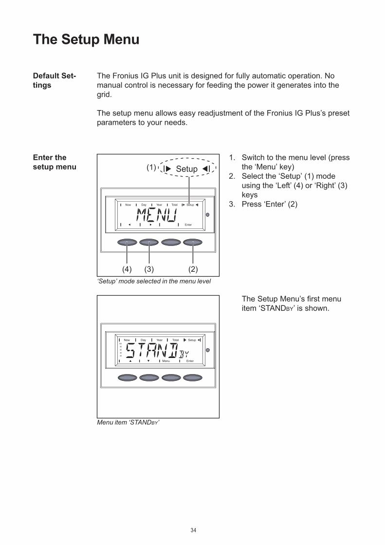
The Fronius IG Plus unit is designed for fully automatic operation. Nomanual control is necessary for feeding the power it generates into thegrid.
The setup menu allows easy readjustment of the Fronius IG Plus’s presetparameters to your needs.
Default Set-tings
Enter thesetup menu (1)
(2)(3)(4)
1. Switch to the menu level (pressthe ‘Menu’ key)
2. Select the ‘Setup’ (1) modeusing the ‘Left’ (4) or ‘Right’ (3)keys
3. Press ‘Enter’ (2)
The Setup Menu’s first menuitem ‘STANDBY’ is shown.
‘Setup’ mode selected in the menu level
Menu item ‘STANDBY’

35
Scrollingamong menuitems
(1) (2) (1) (2)
STANDBYManual activation / deactivation of Standby operation using the ‘Enter’ key
Unit -Setting range EnterFactory setting ‘Standby’ deactivated
- During standby operation the electronic system of the power stage isswitched off. No power is fed into the grid.
- The Operating status LED flashes orange.- The orange flashing Operating Status LED stops at dusk.- After the subsequent sunrise, the power supply operation into the grid
is resumed automatically (after completion of the startup phase theLED is illuminated green).
- Grid supply operation can be resumed at any time whenever the LEDis flashing orange (deactivate ‘STANDBY’)
CONTRASTset contrast on LCD display
Unit -Setting range 0 - 7Factory setting 7
Since contrast depends on temperature, it may be necessary to adjust themenu item ‘Contrast’ when ambient conditions change
Menu Items inthe SetupMenu
1. Open the setup menu2. Scroll among the available menu items using the ‘Up’ (1) and ‘Down’
(2) keys
Example: menu item ‘STANDBY’ Example: menu item ‘CONTRAST’
36
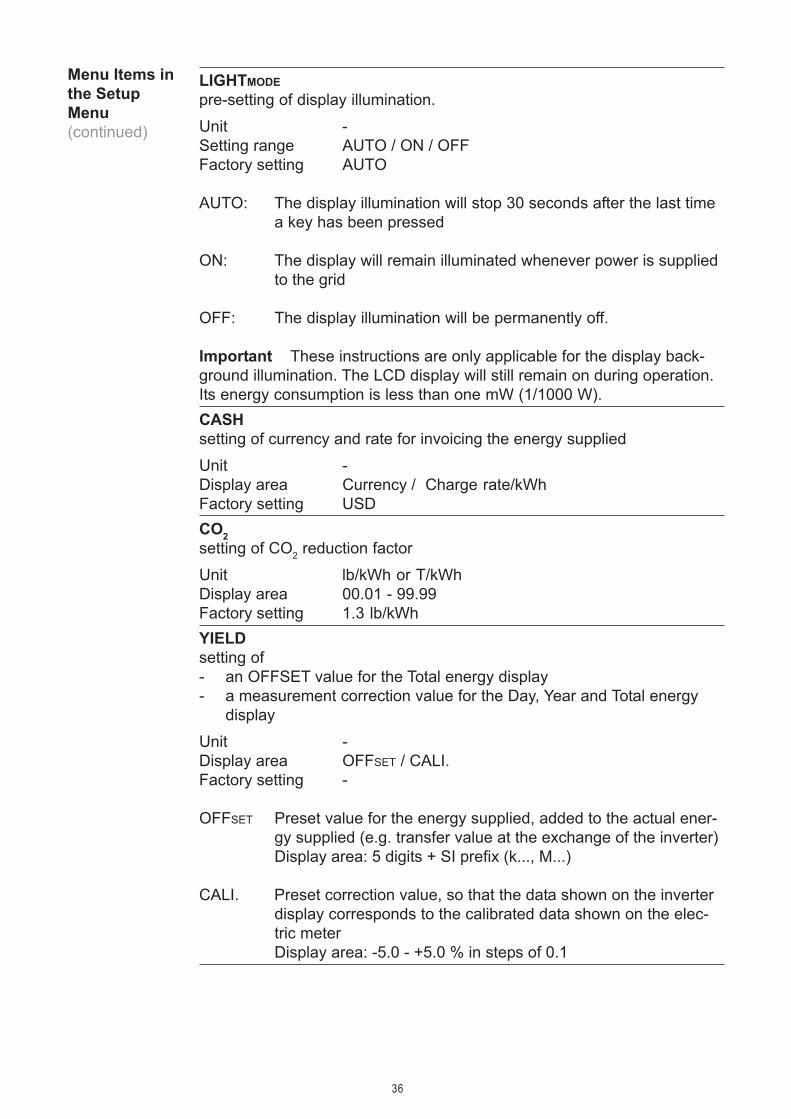
LIGHTMODEpre-setting of display illumination.
Unit -Setting range AUTO / ON / OFFFactory setting AUTO
AUTO: The display illumination will stop 30 seconds after the last timea key has been pressed
ON: The display will remain illuminated whenever power is suppliedto the grid
OFF: The display illumination will be permanently off.
Important These instructions are only applicable for the display back-ground illumination. The LCD display will still remain on during operation.Its energy consumption is less than one mW (1/1000 W).CASHsetting of currency and rate for invoicing the energy supplied
Unit -Display area Currency / Charge rate/kWhFactory setting USDCO2setting of CO2 reduction factor
Unit lb/kWh or T/kWhDisplay area 00.01 - 99.99Factory setting 1.3 lb/kWhYIELDsetting of- an OFFSET value for the Total energy display- a measurement correction value for the Day, Year and Total energy
display
Unit -Display area OFFSET / CALI.Factory setting -
OFFSET Preset value for the energy supplied, added to the actual ener-gy supplied (e.g. transfer value at the exchange of the inverter)Display area: 5 digits + SI prefix (k..., M...)
CALI. Preset correction value, so that the data shown on the inverterdisplay corresponds to the calibrated data shown on the elec-tric meterDisplay area: -5.0 - +5.0 % in steps of 0.1
Menu Items inthe SetupMenu(continued)

37
Menu Items inthe SetupMenu(continued)
IG-NRSetting the number (address) of the Fronius IG Plus unit in a setup com-prising multiple Fronius IG Plus units linked together
Unit -Setting range 01 - 99 (100. Fronius IG Plus = 00)Factory setting 01
Important Allocate a different address to each Fronius IG Plus whenconnecting several Fronius IG Plus into a data communication networkusing the ‘Fronius Com Card’ and a Datalogger.DATCOMindicates status of data transmission, resets the Personal Display Cardand Interface Card
Unit -Setting range Displays OKCOM; PDCDRST / IFCDRST
Factory setting -TIMEsetting of date and time
Unit DDMMYYYY, HH:MMDisplay area Date / TimeFactory setting -
The menu item ‘Time’ is only supported when the Fronius Datalogger isinstalled.STATEPSStatus display of power stage sets; the last error that has occurred canbe displayed
Important State 306 (Power Low) and 307 (DC-Low) appear naturallyevery morning and evening due to low solar irradiance. These statusmessages are not the result of a fault.VERSIONdisplays version number of the IG-Brain and the power stage sets
Unit -Setting range MAINCTRL / LCD / PS (PS00, PS01, PS02)Factory setting -
38
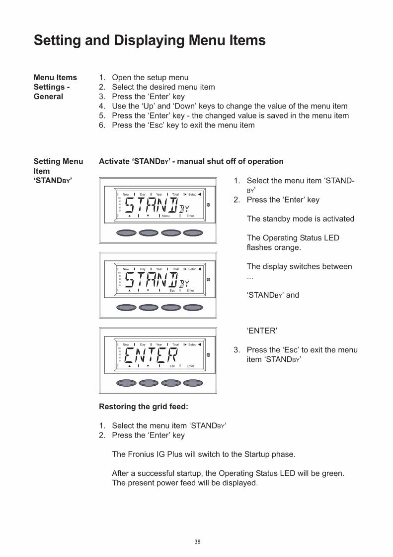
1. Select the menu item ‘STAND-BY’
2. Press the ‘Enter’ key
The standby mode is activated
The Operating Status LEDflashes orange.
The display switches between...
‘STANDBY’ and
1. Open the setup menu2. Select the desired menu item3. Press the ‘Enter’ key4. Use the ‘Up’ and ‘Down’ keys to change the value of the menu item5. Press the ‘Enter’ key - the changed value is saved in the menu item6. Press the ‘Esc’ key to exit the menu item
Restoring the grid feed:
1. Select the menu item ‘STANDBY’2. Press the ‘Enter’ key
The Fronius IG Plus will switch to the Startup phase.
After a successful startup, the Operating Status LED will be green.The present power feed will be displayed.
Activate ‘STANDBY’ - manual shut off of operation
Setting and Displaying Menu Items
Menu ItemsSettings -General
Setting MenuItem‘STANDBY’
‘ENTER’
3. Press the ‘Esc’ to exit the menuitem ‘STANDBY’

39
setting ‘0’ for the minimumpossible contrast
4. Press the ‘Enter’ key to acceptthe setting
5. Press the ‘Esc’ key to exit menuitem ‘CONTRAST’ or to maintainprevious setting
Setting menu
Setting menu
item‘CONTRAST’
1. Select menu item ‘CONTRAST’2. Press the ‘Enter’ key
Setting ‘7’ for maximum possib-le contrast is shown
3. Use the ‘Up’ and ‘Down’ keys toselect the desired level of cont-rast
item‘LIGHTMODE’
1. Select menu item ‘LIGHTMODE’2. Press the ‘Enter’ key
The ‘AUTO’ setting is shown
AUTO ... The display illuminati-on will stop 30 seconds afterthe last time a key has beenpressed.

40
ON ... The display will continueto remain illuminated wheneverpower is supplied to the grid.
OFF ... The display illuminationwill be permanently off.
3. Use the ‘Up’ and ‘Down’ keys toselect the desired setting for thedisplay illumination
4. Press the ‘Enter’ key to acceptthe setting
5. Press the ‘Esc’ key to exit menuitem ‘LIGHTMODE’ or to maintainprevious setting
1. Select menu item ‘CASH’2. Press the ‘Enter’ key
The currency is shownfactory setting = ‘USD’The first character flashes
3. Use the ‘Up’ and ‘Down’ keys toselect a letter for the first cha-racter
4. Press the ‘Enter’ key
The second character flashes
5. Use the ‘Up’ and ‘Down’ keys toselect a letter for the secondcharacter
6. Press the ‘Enter’ key
Setting menuitem‘LIGHTMODE’(continued)
Setting menuitem ‘CASH’
41
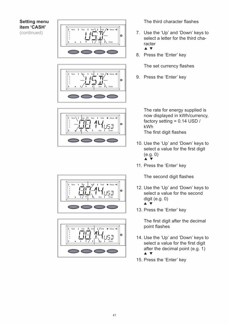
The third character flashes
7. Use the ‘Up’ and ‘Down’ keys toselect a letter for the third cha-racter
8. Press the ‘Enter’ key
The set currency flashes
9. Press the ‘Enter’ key
The rate for energy supplied isnow displayed in kWh/currency,factory setting = 0.14 USD /kWhThe first digit flashes
10. Use the ‘Up’ and ‘Down’ keys toselect a value for the first digit(e.g. 0)
11. Press the ‘Enter’ key
The second digit flashes
12. Use the ‘Up’ and ‘Down’ keys toselect a value for the seconddigit (e.g. 0)
13. Press the ‘Enter’ key
The first digit after the decimalpoint flashes
14. Use the ‘Up’ and ‘Down’ keys toselect a value for the first digitafter the decimal point (e.g. 1)
15. Press the ‘Enter’ key
Setting menuitem ‘CASH’(continued)

42
The second digit after the deci-mal point flashes
16. Use the ‘Up’ and ‘Down’ keys toselect a value for the seconddigit after the decimal point(e.g. 4)
The values that can be setrange from 00.01 to 99.99
17. Press the ‘Enter’ key
The set rate for energy suppliedflashes
18. Press the ‘Enter’ key
The currency and the rate forsupplied energy are now accep-ted
19. Press the ‘Esc’ key to exit menuitem ‘CASH’ or to maintainprevious setting
Setting menuitem ‘CASH’(continued)
Setting menuitem ‘CO2’
1. Select menu item ‘CO2’2. Press the ‘Enter’ key
The CO2 reduction factor isshown;the first digit flashes
3. Use the ‘Up’ and ‘Down’ keys toselect a value for the first digit
4. Press the ‘Enter’ key

43
Setting menuitem ‘CO2’(continued)
The first digit after the decimalpoint flashes
7. Use the ‘Up’ and ‘Down’ keys toselect a value for the first digitafter the decimal point
8. Press the ‘Enter’ key
The second digit after thedecimal point flashes
9. Use the ‘Up’ and ‘Down’ keys toselect a value for the seconddigit after the decimal point
10. Press the ‘Enter’ key
The set CO2 reduction factorflashes
11. Press the ‘Enter’ key
The set CO2 reduction factor isnow accepted
12. Press the ‘Esc’ key to exit menuitem ‘CO2’ or to maintain pre-vious setting
Setting menuitem ‘YIELD’
1. Select menu item ‘YIELD’2. Press the ‘Enter’ key
The second digit flashes
5. Use the ‘Up’ and ‘Down’ keys toselect a value for the first digit
6. Press the ‘Enter’ key

44
Setting menuitem ‘YIELD’(continued)
The OFFSET value is shown, thefirst digit flashs
3. Use the ‘Up’ and ‘Down’ keys toselect a value for the first digit
4. Press the ‘Enter’ key
The second digit of the OFFSET
value flashes
5. Use the ‘Up’ and ‘Down’ keys toselect a value for the seconddigit
6. Press the ‘Enter’ key
The third digit of the OFFSET
value flashes
7. Use the ‘Up’ and ‘Down’ keys toselect a value for the third digit
8. Press the ‘Enter’ key
The fourth digit of the OFFSET
value flashes
9. Use the ‘Up’ and ‘Down’ keys toselect a value for the fourthdigit
10. Press the ‘Enter’ key
The fifth digit of the OFFSET
value flashes
11. Use the ‘Up’ and ‘Down’ keys toselect a value for the fifth digit
12. Press the ‘Enter’ key
‘OFFset’ is shown
3. Press the ‘Enter’ key

45
Setting menuitem ‘YIELD’(continued)
The digit for the SI prefix flas-hes
13. Use the ‘Up’ and ‘Down’ keys toselect the SI prefix:k = 1000M = 1000000
14. Press the ‘Enter’ key
The set OFFSET value and theSI prefix flash
15. Press the ‘Enter’ key
The set OFFSET value is nowaccepted.
‘CALI.’ is shown
17. Press the ‘Enter’ key
The correction value in % isshown, the digit for the signflashes
18. Use the ‘Up’ and ‘Down’ keys toselect a sign for the correctionvalue
19. Press the ‘Enter’ key
The digit before the decimalpoint flashes
20. Use the ‘Up’ and ‘Down’ keys toselect a value for the digitbefore the decimal point
21. Press the ‘Enter’ key
‘OFFSET’ is shown
16. Press the ‘Up’ or ‘Down’ key

46
Setting menuitem ‘IG-NR’
1. Select menu item ‘IG-NR’2. Press the ‘Enter’ key
The inverter number is shown,the first digit flashes.
3. Use the ‘Up’ and ‘Down’ keys toselect a value for the first digit
4. Press the ‘Enter’ key
The second digit flashes
5. Use the ‘Up’ and ‘Down’ keys toselect a value for the seconddigit
6. Press the ‘Enter’ key
The digit after the decimal pointflashes
22. Use the ‘Up’ and ‘Down’ keys toselect a value for the digit afterthe decimal point
23. Press the ‘Enter’ key
The set correction value flashes
24. Press the ‘Enter’ key
The set correction value is nowaccepted
‘CALI.’ is shown
25. Press the ‘Esc’ key 2 x to exitmenu item ‘YIELD’ or tomaintain previous setting
Setting menuitem ‘YIELD’(continued)

47
Available data connection
If there is a data connectionavailable, ‘OKCOM’ is shown.
3. Use the ‘Down’ key to selectavailable data:
e.g. Reset Personal DisplayCard (‘PDCDRST’) ...
... or Reset Interface Card(‘IFCDRST’)
4. Press the ‘Enter’ key
Setting menuitem ‘DATCOM’
1. Select menu item ‘DATCOM’2. Press the ‘Enter’ key
The following displays dependon whether- a data connection is avai-
lable- a data connection is faulty
or an option is not installed
The set inverter number nowflashes
7. Press the ‘Enter’ key
The number is accepted
8. Press the ‘Esc’ key to exit menuitem ‘IG-NR’ or to maintainprevious setting
Setting menuitem ‘IG-NR’(continued)

48
Setting menuitem ‘DATCOM’(continued)
‘PDCDDONE’ ...
... or ...
‘IFCDDONE’ is shown
5. Press the ‘Esc’ key 2x to exitmenu item ‘DATCOM’
Data connection faulty or an option is not installed
If there is a faulty data connec-tion or options are not installed‘ERRORCOM’ is shown.
3. Press the ‘Esc’ key to exit menuitem ‘DATCOM’
Setting menuitem ‘TIME’
1. Select menu item ‘TIME’2. Press the ‘Enter’ key
The date is shown(DD.MM.YYYY), the first digitfor the day flashes
3. Use the ‘Up’ and ‘Down’ keys toselect a value for the first daydigit
4. Press the ‘Enter’ key
The second day digit flashes
5. Use the ‘Up’ and ‘Down’ keys toselect a value for the secondday digit
6. Press the ‘Enter’ key

49
The first digit for the year flas-hes
11. Use the ‘Up’ and ‘Down’ keys toselect a value for the first yeardigit
12. Press the ‘Enter’ key
The second digit for the yearflashes
13. Use the ‘Up’ and ‘Down’ keys toselect a value for the secondyear digit
14. Press the ‘Enter’ key
The third digit for the yearflashes
15. Use the ‘Up’ and ‘Down’ keys toselect a value for the third yeardigit
16. Press the ‘Enter’ key
The first digit for the monthflashes
7. Use the ‘Up’ and ‘Down’ keys toselect a value for the firstmonth digit
8. Press the ‘Enter’ key
The second digit for the monthflashes
9. Use the ‘Up’ and ‘Down’ keys toselect a value for the secondmonth digit
10. Press the ‘Enter’ key
Setting menuitem ‘TIME’(continued)

50
Setting menuitem ‘TIME’(continued)
The fourth digit for the yearflashes
17. Use the ‘Up’ and ‘Down’ keys toselect a value for the fourthyear digit
18. Press the ‘Enter’ key
The set date then flashes:
19. Press the ‘Enter’ key
The first digit for the minutesflashes
24. Use the ‘Up’ and ‘Down’ keys toselect a value for the first minu-tes digit
25. Press the ‘Enter’ key
The time is shown (HH:MM, 0 -24 h), the first digit for the hourflashes
20. Use the ‘Up’ and ‘Down’ keys toselect a value for the first hourdigit
21. Press the ‘Enter’ key
The second digit for the hourflashes
22. Use the ‘Up’ and ‘Down’ keys toselect a value for the secondhour digit
23. Press the ‘Enter’ key

51
The display switches between...
‘STATELAST’
and
Displayingmenu item‘STATEPS’
1. Select menu item ‘STATEPS’2. Press the ‘Enter’ key
The status of the first powerstage set PS00 is shown, e.g.:STDBYPSOO
STDBY = standby (no grid feed)
3. Press the ‘Enter’ key to displaythe last status message saved
The set time flashes
28. Press the ‘Enter’ key to applythe time
29. Press the ‘Esc’ key to exit menuitem ‘TIME’ or to maintain pre-vious setting
The second digit for the minu-tes flashes
26. Use the ‘Up’ and ‘Down’ keys toselect a value for the secondminutes digit
27. Press the ‘Enter’ key
Setting menuitem ‘TIME’(continued)

52
the last saved status message.
4. Press the ‘Esc’ key
The status of the first powerstage set PS00 is shown again
5. Use the ‘Down’ key to select thesecond or third power stage setPS01 or PS02, if available.
The status of the selectedpower stage set is shown, e.g.:RUNPSO1
RUN = active grid feed
6. Press the ‘Enter’ key to displaythe last status message saved
Displayingmenu item‘STATEPS(continued)
the last saved status message.
7. Press the ‘Esc’ key 2x to exitmenu item ‘STATEPS’
The display switches between...
‘STATELAST’
and
1. Select menu item ‘VERSION’2. Press the ‘Enter’ key
Displayingmenu item‘VERSION’

53
The identification number of theIG Brain unit is shown
6. Press the ‘Down’ key to displaythe hardware version of the IGBrain unit
The hardware version of the IGBrain unit is shown
7. Press the ‘Esc’ key
‘MAINCTRL’ is shown
8. Press the ‘Down’ key to displaythe power stage sets
The component ID of the IGBrain unit is shown
5. Press the ‘Down’ key to displaythe identification number of theIG Brain unit
The version number of the IGBrain unit is shown
4. Press the ‘Down’ key to displaythe component ID.
‘MAINCTRL’ is shown
3. Press ‘Enter’ to display theversion number of the IG Brainunit
Displayingmenu item‘VERSION’(continued)

54
‘PS’ is shown
9. Press the ‘Enter’ key
The first power stage set ‘PS00’ is shown
10. Select the desired power stageset using the ‘Down’ key
11. Press the ‘Enter’ key
The version number of theselected power stage set isshown
12. Press the ‘Down’ key to displaythe component ID
The identification number of theselected power stage set isshown
14. Press the ‘Down’ key to displaythe hardware version of thepower stage set
The hardware version of theselected power stage set isshown
15. Press the ‘Esc’ key
The component ID of the se-lected power stage set is shown
13. Press the ‘Down’ key to displaythe power stage set identificati-on number
Displayingmenu item‘VERSION’(continued)

55
‘PS’ is shown
17. Press the ‘Esc’ key to exit menuitem ‘VERSION’
The selected power stage set isshown
16. Press the ‘Esc’ key
Displayingmenu item‘VERSION’(continued)

56

57
Installation and Startup

58

59
Fronius IGPlusConstruction
The power stage set and the con-nection area are separated fromeach other for delivery.
Safety WARNING! An electrical shock can be fatal. Danger from gridvoltage and DC voltage from solar modules.- The connection area should only be opened by a licensed
electrician.- The separate power stage set area should only be discon-
nected from the connection area after first being discon-nected from the grid power.
- The separate power stage set area should only be openedby Fronius-trained service personnel.
Never work with live wires! Prior to all connection work, makesure that the AC and DC wires are not charged.
Fronius IG Plus Installation and Connection
Connection area
Power stage set(s)
Connection area and power stage set onthe Fronius IG Plus
WARNING! Incorrect operation and work performed incorrectlycan cause serious injury & damage! Only qualified staff areauthorized to install your Fronius IG Plus and only within thescope of the respective technical regulations. Do not startoperation or carry out maintenance work before you have readthe chapter ‘Safety Instructions’!
60
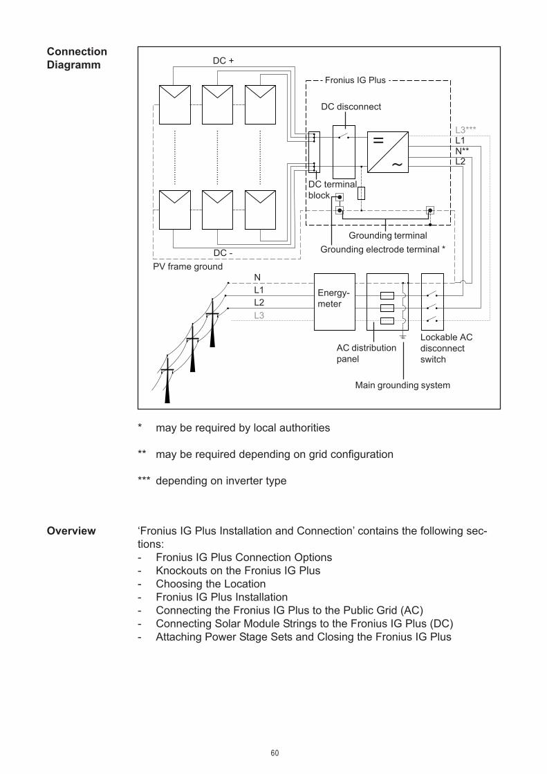
ConnectionDiagramm
Fronius IG Plus
Energy-meter
AC distributionpanel
DC disconnect
DC terminalblock
DC +
DC -PV frame ground
L1L2
N
Grounding terminalGrounding electrode terminal *
L1N**L2
L3
L3***
Main grounding system
* may be required by local authorities
** may be required depending on grid configuration
*** depending on inverter type
Lockable ACdisconnectswitch
Overview ‘Fronius IG Plus Installation and Connection’ contains the following sec-tions:- Fronius IG Plus Connection Options- Knockouts on the Fronius IG Plus- Choosing the Location- Fronius IG Plus Installation- Connecting the Fronius IG Plus to the Public Grid (AC)- Connecting Solar Module Strings to the Fronius IG Plus (DC)- Attaching Power Stage Sets and Closing the Fronius IG Plus

61
Connections on the Fronius IG Plus
Item Description(1) Jumper slot SMON
(2) DC+ main switch wire(3) 6 x fuse holder with fuse cover, for stringfuses(4) Jumper slot SMOFF
(5) Plug-in card IG Brain(6) Open card slot for an option card(7) Open card slot for an option card(8) Plug-in card NL-MON
Only at Fronius IG Plus 12.0-3 WYE 277: Open card slot for anoption card
(9) DC- main switch wire(10) 6 DC- terminals(11) fuse holder with fuse cover, for GFDI-fuse
(1) (7)(6)(3) (5)(4)(2)
(9)(10)
(8)
(11)(12)(13)(14)(15)(16)
Fronius IG Plus Connection Options
Fronius IGPlus Connec-tion Options

62
Item Description(12) AC-side terminals(13) 3 x grounding terminals(14) Strain relief for solar module strings(15) 6 DC+ terminals(16) DC main switch
Fronius IGPlus Connec-tion Options(continued)

63
The Fronius IG Plus contains several knockouts of different sizes. Whenknocked out, the openings are used for the inputs of various wires.
Knockouts on the lefthand side
Item Description(1) Knockout, diameter 3/4 in. / 1 in.
e.g. for DC wire, surge arrester(2) Knockout, diameter 1/2 in. / 3/4 in.
only for data wires(3) Knockout, diameter 3/4 in. / 1 in.
e.g. for AC wire, surge arrester(4) Knockout, diameter 1/2 in. / 3/4 in.
e.g. for AC wire, surge arrester
(2)
(1)
Knockouts on the righthand side
(3)
(1)
(3)(2)
(4)(1)(5) (3) (4)(3)(5)(1)
(2)
Knockouts on the underside Knockouts on the backside
(6)
(7)
Knockouts forWire Inputs
Knockouts on the Fronius IG Plus
General

64
Knockouts forWire Inputs(continued)
NOTE When using back wire inputs:- seal on enclosure NEMA 3R before outside operation
NOTE- The larger knockouts should only be removed from the out-
side in.- The smaller knockouts should be removed from the inside
out.- Only remove the number of knockouts required for the avai-
lable wire inputs
CAUTION! Danger of damaging the plastic base when remo-ving the knockouts on the bottom.- Before removing, remove the 3 fixing screws (6) and (7)- Remove the metal insert from the plastic base- Remove the required knockouts- Replace the metal insert into the plastic base- Secure the metal insert using the 3 fixing screws (6) and (7)
Item Description(5) Knockout, diameter 1/2 in. / 3/4 in.
e.g. for DC wire, surge arrester(6) FTX 25 fixing screws(7) FTX 25 fixing screw

65
During certain operation phases the Fronius IG Plus unit may produce aslight noise. For this reason it should not be installed in an occupied livingarea.Do not install the Fronius IG Plus in:- areas with large amounts of dust- areas with large amount of conducting dust particles (e.g. iron filings)- areas with corrosive gases, acids or salts- areas where there is an increased risk of accidents, e.g. from farm
animals (horses, cattle, sheep, pigs, etc.)- Stables or adjoining areas- Storage areas for hay, straw, chaff, animal feed, fertilizers, etc.- Storage or processing areas for fruit, vegetables or winegrowing pro-
ducts- Rooms used in the preparation of grain, green fodder or animal feeds- Greenhouses
Choosing aLocation forInside Installa-tion
Choosing the Location
Please note the following criteria when choosing a location for the FroniusIG Plus:
Only vertical installationMax. ambient temperatures: -4 °F / +122 °F (-20 °C / +50 °C)Keep a distance of 8 in. (20 cm) minimum between each inverter oranything to the right or left of the inverters such as walls or DC and ACdisconnects.For optimal airflow and cooling efficiency in hot climates Fronius recom-mend a distance of 10 - 12 in. (25 - 30 cm).When installing more than one unit, keep a distance of 12 in. (30 cm)between each Fronius IG Plus.The air flow direction within the inverter is from right to left (cold air intakeon right, hot air exit on left).When installing the Fronius IG Plus unit in a switch panel cabinet (orsimilar closed environment) it is necessary to make sure that the hot airthat develops will be discharged by forced ventilation.The Fronius IG Plus is designed for installation both indoors andoutdoors.
Choosing thelocation gene-ral

66
NEMA 3R protection means that the Fronius IG Plus can be exposed tomoisture. However, we recommend that direct moisture be avoided, ifpossible.In order to protect the display, the Fronius IG Plus should not be exposedto direct sunlight. Ideally, the Fronius IG Plus should be installed in aprotected location, e.g. near the solar modules or under a roof overhang.
Choosing aLocation forOutside Instal-lation
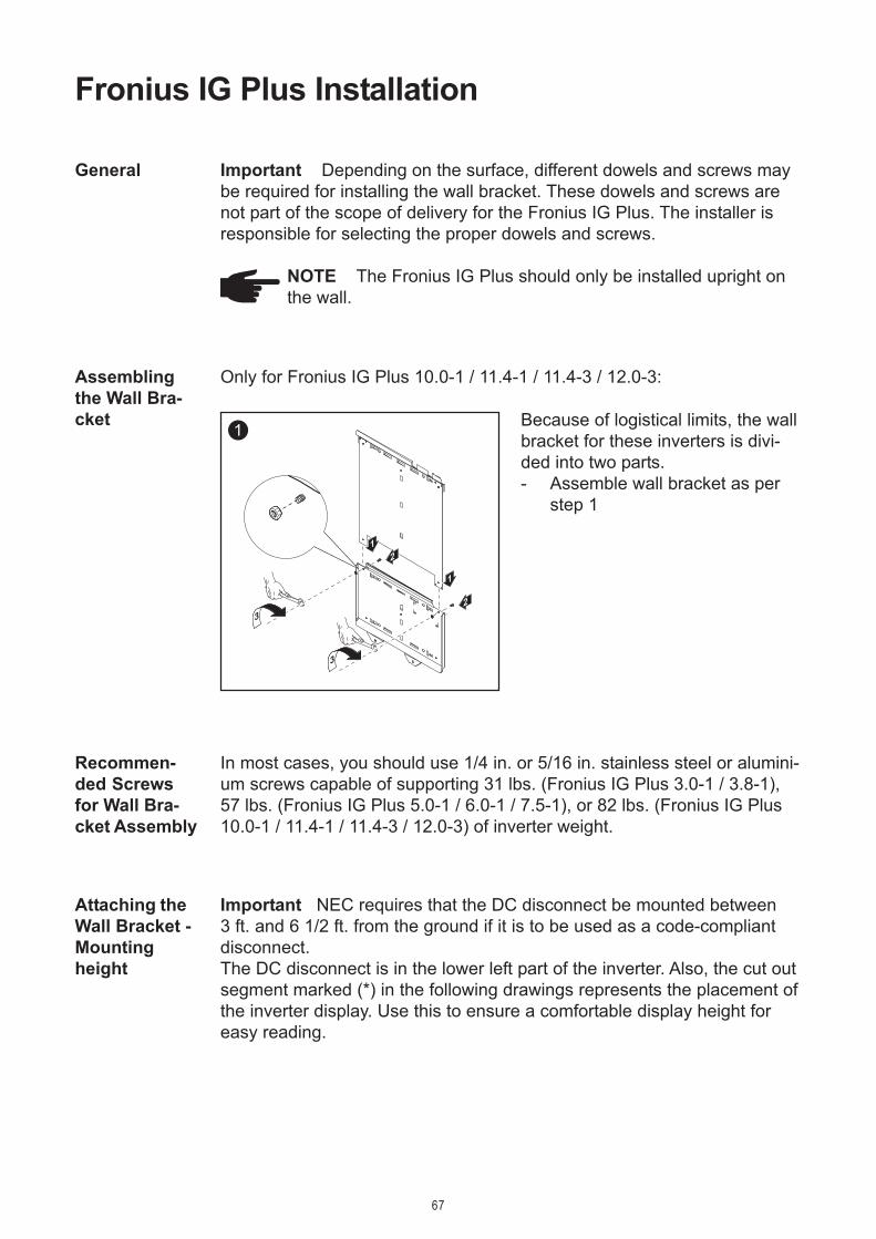
67
Important Depending on the surface, different dowels and screws maybe required for installing the wall bracket. These dowels and screws arenot part of the scope of delivery for the Fronius IG Plus. The installer isresponsible for selecting the proper dowels and screws.
NOTE The Fronius IG Plus should only be installed upright onthe wall.
1
1
1
2
2
3
3
General
Because of logistical limits, the wallbracket for these inverters is divi-ded into two parts.- Assemble wall bracket as per
step 1
Only for Fronius IG Plus 10.0-1 / 11.4-1 / 11.4-3 / 12.0-3:
Recommen-ded Screwsfor Wall Bra-cket Assembly
Fronius IG Plus Installation
Assemblingthe Wall Bra-cket
In most cases, you should use 1/4 in. or 5/16 in. stainless steel or alumini-um screws capable of supporting 31 lbs. (Fronius IG Plus 3.0-1 / 3.8-1),57 lbs. (Fronius IG Plus 5.0-1 / 6.0-1 / 7.5-1), or 82 lbs. (Fronius IG Plus10.0-1 / 11.4-1 / 11.4-3 / 12.0-3) of inverter weight.
Attaching theWall Bracket -Mountingheight
Important NEC requires that the DC disconnect be mounted between3 ft. and 6 1/2 ft. from the ground if it is to be used as a code-compliantdisconnect.The DC disconnect is in the lower left part of the inverter. Also, the cut outsegment marked (*) in the following drawings represents the placement ofthe inverter display. Use this to ensure a comfortable display height foreasy reading.

68
3
2
6 x
4
6
7
1
5
23
2
22
3
4
1
6
5
Important The cut out segment marked (*) represents the placement ofthe inverter display. Use this to ensure a comfortable display height foreasy reading.
1
2
1
1
7
3
5
4
6
(*)
Attaching theWall Bracketto a Concreteor Brick Wall
Attaching theWall Bracketto a WoodenWall
9
1
1
1
2
3
4
(*)
9
2
1
2
5
Important The cut out segment marked (*) represents the placement ofthe inverter display. Use this to ensure a comfortable display height foreasy reading.

69
Fronius IGPlus Installati-on
Attaching theWall Bracketto a MetalCarrier
1
4 x
3
4
22
1
(*)
Important The cut out segment marked (*) represents the placement ofthe inverter display. Use this to ensure a comfortable display height foreasy reading.
NOTE When installingusing a metal carrier, theFronius IG Plus should notbe exposed to rainwater orwater spray at the back.Ensure proper rainwater orspray water protection.
1
2
1
1
2
2
3
2
1
4
1
2 34
65
7
8

70
Fronius IGPlus Installati-on(continued)
Installation ofSeveral Inver-ters
Several inverters can be easily installed and connected next to each otherusing the side knockouts on the Fronius IG Plus, e.g.:
DC DC DC
DATCOM = data communication
NOTE All electrical installations must be made in accordancewith the National Electrical Code, ANSI/NFPA 70, and any othercodes and regulations applicable to the installation site.
For installations in Canada the installations must be done inaccordance with applicable Canadian standards.
DATCOM DATCOM
AC AC
CAUTION! Danger of injury by falling equipment.Attach the connection area of the inverter to the wall bracketusing the 2 screws removed from the wall bracket in step 1.
5
2
1
6
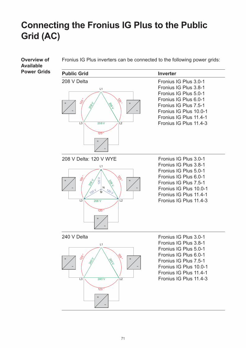
71
Connecting the Fronius IG Plus to the PublicGrid (AC)
Overview ofAvailablePower Grids
120
° 120 °
120 °
208 V
208 V
208 V
L1
L2L3
=
~
=
~
=
~
Fronius IG Plus inverters can be connected to the following power grids:
Public Grid Inverter208 V Delta Fronius IG Plus 3.0-1
Fronius IG Plus 3.8-1Fronius IG Plus 5.0-1Fronius IG Plus 6.0-1Fronius IG Plus 7.5-1Fronius IG Plus 10.0-1Fronius IG Plus 11.4-1Fronius IG Plus 11.4-3
Fronius IG Plus 3.0-1Fronius IG Plus 3.8-1Fronius IG Plus 5.0-1Fronius IG Plus 6.0-1Fronius IG Plus 7.5-1Fronius IG Plus 10.0-1Fronius IG Plus 11.4-1Fronius IG Plus 11.4-3
120
V
120 V 120 V
120
° 120 °
120 °
208
V 208 V
208 V
L1
L2
N
L3
=
~
=
~
=
~
208 V Delta: 120 V WYE
Fronius IG Plus 3.0-1Fronius IG Plus 3.8-1Fronius IG Plus 5.0-1Fronius IG Plus 6.0-1Fronius IG Plus 7.5-1Fronius IG Plus 10.0-1Fronius IG Plus 11.4-1Fronius IG Plus 11.4-3
240 V240 V
240 V
120
° 120 °
120 °
L1
L2L3
=
~
=
~
=
~
240 V Delta

72
Overview ofAvailablePower Grids(continued)
Public Grid Inverter240 V: 120 V Stinger
240 V240
V120
° 120 °
120 °
120 V120 V
L3
L1N
L2
=
~
=
~
=
~
240 V: 120 V Split phase
Fronius IG Plus 3.0-1Fronius IG Plus 3.8-1Fronius IG Plus 5.0-1Fronius IG Plus 6.0-1Fronius IG Plus 7.5-1Fronius IG Plus 10.0-1Fronius IG Plus 11.4-1
180 °
120 V 120 V
240 V
L1 L2N
=
~
Fronius IG Plus 3.0-1Fronius IG Plus 3.8-1Fronius IG Plus 5.0-1Fronius IG Plus 6.0-1Fronius IG Plus 7.5-1Fronius IG Plus 10.0-1Fronius IG Plus 11.4-1
480 V Delta: 277 V WYE
277
V
277 V 277 V
120
° 120 °
120 °
480
V 480V
480 V
L1
L2
N
L3
=
~
=
~
=
~
Fronius IG Plus 3.0-1Fronius IG Plus 3.8-1Fronius IG Plus 5.0-1Fronius IG Plus 6.0-1Fronius IG Plus 7.5-1Fronius IG Plus 10.0-1Fronius IG Plus 11.4-1
Fronius IG Plus 12.0-3

73
NOTE For optimal functioning of grid monitoring the resistancein the leads to the AC side connection terminals must be as lowas possible.The AC conductor resistance between the Fronius IG Plus unitand the building’s distribution panel should not exceed 0.5 Ohm.
Monitoring theGrid
For larger photovoltaic schemes it is possible to connect several FroniusIG Plus units in parallel without any problems.To ensure symmetrical feeding, connect the inverters uniformly to allphases.
NOTE The Fronius IG Plus is designed to be connected tothree phase systems. Utilities generally allow up to 6 kVA ofunbalance but check with your utility and try to balance the instal-lation. The connection to the grid shall be done in the followingway:
208 V / 240 V:- Connect Fronius IG Plus No. 1, No. 4, No. 7, ... to L1 and L2- Connect Fronius IG Plus No. 2, No. 5, No. 8, ... to L2 and L3- Connect Fronius IG Plus No. 3, No. 6, No. 9, ... to L1 and L3
277 V:- Connect Fronius IG Plus No. 1, No. 4, No. 7, ... to L1 and N- Connect Fronius IG Plus No. 2, No. 5, No. 8, ... to L2 and N- Connect Fronius IG Plus No. 3, No. 6, No. 9, ... to L3 and N
Schemes withmore than oneinverter
NOTE Do not connectFronius IG Plus invertersto the 480 V Delta powergrid.
480 V480 V
480 V
120
° 120 °
120 °
L1
L2L3
=
~
=
~
=
~
480 V DeltaOverview ofAvailablePower Grids(continued)

74
AC-side Termi-nals
The AC-side terminals are designed for the following terminal connec-tions:
Grounding Terminals:
(1) Grounding Electrode Terminal(2) Terminal for possible grounding of the solar module frame(3) Grid grounding / Grounding conductor
AC-side Terminals:
L1 = Phase conductor L1L2 = Phase conductor L2L3 = Phase conductor L3N = Neutral conductor NN.C. = Not connectedGET = Grounding Electrode Terminal
max. wire cross section AWG 4
NOTEThe neutral conductor is not bonded to ground internally.
Depending on the installation, an additional external AC and/or DC dis-connect may be required if the inverter is installed in a location not easilyaccessible to utility or fire personnel. Consult local authorities for additio-nal information.
(1)(2) (3)
AC-side Terminals
2-phase inverters 208 V / 240 V
2-phase inverters 277 V
3-phase inverters 208 V / 240 V / 277 V
L1 L2 N
N.C.L1 L2
L3L1 L2 N
GET
GET
GET

75
Cross Sectionof AC Wires
WARNING! An electric shock can be fatal. Inadequately sizedelectrical components can cause serious injuries to personsand damage to (or loss of) property.- All electrical installations must be in accordance with the
National Electrical Code, ANSI/NFPA 70, and any othercodes and regulations applicable to the installation site.
- For installations in Canada the installations must be done inaccordance with applicable Canadian standards.
- Use minimum AWG 10, min. 167 °F (75 °C), copper wire forall grounding wires.
- Use minimum AWG 14 to maximum AWG 4, min. 167°F(75°C), copper wire for all AC wiring connections to theFronius IG Plus. Voltage drop and other considerations maydictate larger size wires be used.
- Use only solid or stranded wire. Do not use fine strandedwire.
Fronius IG Plus AC wire AC wire AC wire208 V 240 V 277 V
3.0-1 AWG 12 AWG 14 AWG 143.8-1 AWG 12 AWG 12 AWG 125.0-1 AWG 8 AWG 10 AWG 126.0-1 AWG 8 AWG 8 AWG 107.5-1 AWG 6 AWG 6 AWG 810.0-1 AWG 4 AWG 4 AWG 611.4-1 AWG 4 AWG 4 AWG 411.4-3 AWG 8 AWG 8 -12.0-3 - - AWG 12Minimum cross section of AC wires
Safety
WARNING! An electrical shock can be fatal. Danger from gridvoltage and DC voltage from solar modules.- The connection area should only be opened by a licensed
electrician.- The separate power stage set area should only be discon-
nected from the connection area after first being discon-nected from the grid power.
Never work with live wires! Prior to all connection work, makesure that the AC and DC wires are not charged.
Only an authorized electrician is permitted to connect this inverter to thepublic grid.

76
4
2
1
Connectingthe Fronius IGPlus to thePublic Grid(AC)
L1 L2 N
2 phases - 277 V
GETGET
1
1
2
Conduit
NOTE Only use water tight conduit fittings and conduits.Conduit fittings and conduits are not part of the scope of deliveryfor the inverter
1/2 in.
3
1
*
* Connect grid grounding / grounding conductor to the right terminal** Tightening torque:
- stranded wires .............. 1.25 ft. lb.- solid wires ..................... 0.81 ft. lb.
Connect the AC wires to the AC-side terminals depending on the powergrid and phase quantity of the inverter:
L1 N N.C.
NOTEForm a min. 4 in. wire loop using all wires.
**
2 phases - 208 V / 240 V
3 phases - 208 V / 240 V / 277 V
L1 L2 NL3GET = Grounding Electrode TerminalN.C. = Not connected

77
Recommenda-tion for theAC-side overcurrent pro-tection
NOTE To reduce the risk of fire, connect only to a circuit provi-ded with branch circuit overcurrent protection in accordance withthe National Electrical Code, ANSI / NFPA 70, at a MAXIMUM of:
Fronius IG Plus Over Current Protection208 V 240 V 277 V
3.0-1 20 A 20 A 15 A3.8-1 25 A 20 A 20 A5.0-1 30 A 30 A 25 A6.0-1 40 A 35 A 30 A7.5-1 45 A 40 A 35 A10.0-1 60 A 60 A 45 A11.4-1 70 A 60 A 60 A11.4-3 40 A 35 A -12.0-3 - - 20 A

78
WARNING! An electrical shock can be fatal. Danger from gridvoltage and DC voltage from solar modules.- The connection area should only be opened by a licensed
electrician.- The separate power stage set area should only be discon-
nected from the connection area after first being discon-nected from the grid power.
- The separate power stage set area should only be openedby Fronius-trained service personnel.
Never work with live wires! Prior to all connection work, makesure that the AC and DC wires are not charged.
The DC main switch is only used to switch off power to thepower stage set. When the DC main switch is turned off, theconnection area is still energized.
Connecting Solar Module Strings to the FroniusIG Plus (DC)
In order to select suitable solar modules and get the most efficient use outof the Fronius IG Plus, please note the following points:
- The open circuit voltage increases when temperature decreases(assuming constant irradiance of 1000 W/m²). The inverter open-circuit voltage should never rise above 600 Volts.Whenever the open-circuit voltage of the solar modules exceeds 600Volts, the Fronius IG Plus unit may be damaged, and all warrantyrights will become null and void.
- More exact data for sizing the solar array for the particular locationcan be obtained using calculation tools such as the Fronius Configura-tion Tool (available on http://www.fronius-usa.com).
- See NEC table 690.7 for the appropriate code-related voltage adjust-ment factor for crystalline silicon modules, or use the manufacturer’sspecified voltage coefficient.
General Infor-mation AboutSolar Modules
Safety
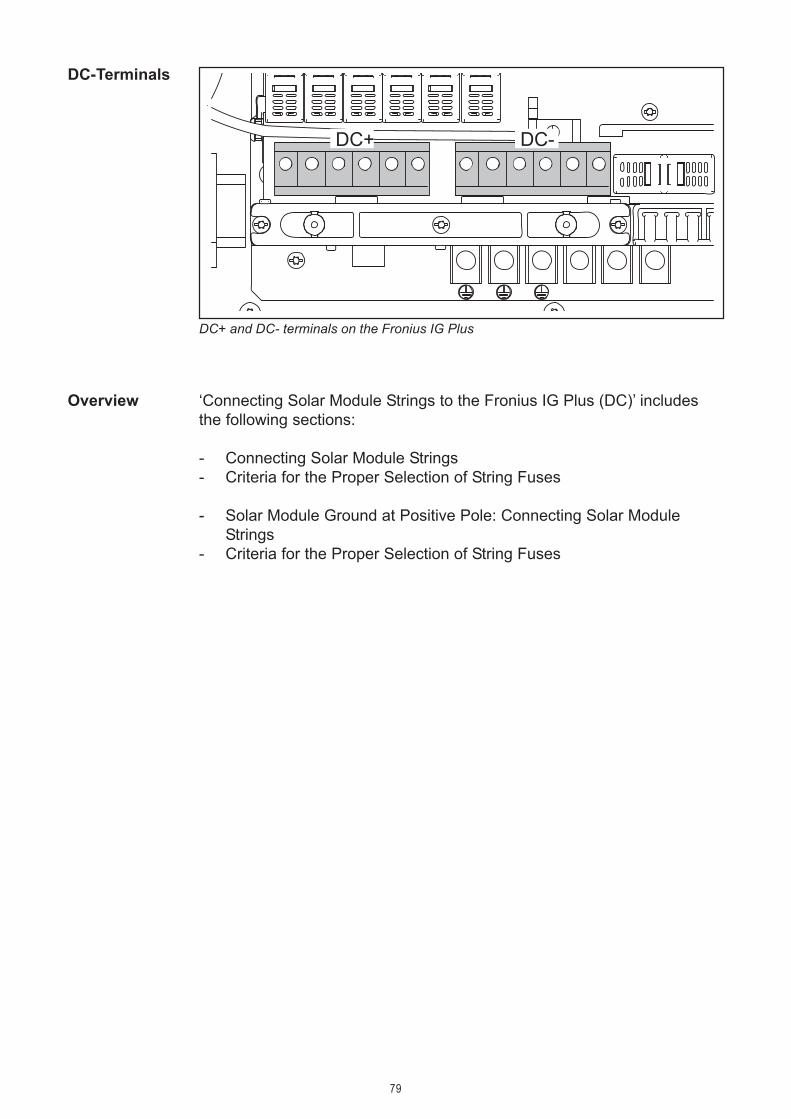
79
DC+ and DC- terminals on the Fronius IG Plus
DC+ DC-
Overview ‘Connecting Solar Module Strings to the Fronius IG Plus (DC)’ includesthe following sections:
- Connecting Solar Module Strings- Criteria for the Proper Selection of String Fuses
- Solar Module Ground at Positive Pole: Connecting Solar ModuleStrings
- Criteria for the Proper Selection of String Fuses
DC-Terminals

80
WARNING! An electric shock can be fatal. Inadequately sizedelectrical components can cause serious injuries to personsand damage to (or loss of) property.- All electrical installations must be in accordance with the
National Electrical Code, ANSI/NFPA 70, and any othercodes and regulations applicable to the installation site.
- For installations in Canada the installations must be done inaccordance with applicable Canadian standards.
- Use minimum AWG 10, min. 167 °F (75 °C), copper wire forall grounding wires.
Connecting Solar Module Strings
The Fronius IG Plus is designed for a solar module ground at the negativepole. The solar module ground is carried out via a fuse in the inverter.
Solar ModuleGround
=~
=~
DC+
DC-
Inverter
NL1
GND
Solar module
Solar module ground at negative pole with fuse
DC main switch
Wire CrossSection ofSolar ModuleStrings
WARNING! An electric shock can be fatal. Normally groundedconductors may be ungrounded and energized when a groundfault is indicated. The ground fault has to be repaired beforeoperation is resumed.
L3L2
NOTE Do not connect the ground to the DC negative at anypoint! This is already done within the Fronius IG Plus. If the DCnegative is connected to ground at the DC terminal block or prior,this will circumvent the GFDI protection system, preventing yourFronius IG Plus from properly detecting a fault current. Additional-ly, turning the DC disconnect to the off/open-circuit condition willnot disconnect the array from ground, as it only disconnects theDC positive.
GFDI fuse
String fuse

81
ConnectingSolar ModuleStrings
Wire CrossSection ofSolar ModuleStrings(continued)
1
1
2
1
CAUTION! Danger of damaging the inverter by overload.Connect a maximum of 20 A per solar module string to one DCterminal - maximum of 6 solar module strings.
NOTE Only use water tight conduit fittings and conduits.Conduit fittings and conduits are not part of the scope of deliveryfor the inverter.
1
3
3
1/2 in.
2
4
5 4
6
4
2
1
* Wire for solar module grounding
Conduit
WARNING! An electric shock can be fatal. Inadequately sizedelectrical components can cause serious injuries to personsand damage to (or loss of) property.- Use minimum AWG 14 to maximum AWG 6, min. 167°F
(75°C), copper wire for all DC wiring connections to theFronius IG Plus. Voltage drop and other considerations maydictate larger size wires be used.
- Use only solid or stranded wire. Do not use fine strandedwire
Tightening torque:stranded wires ................ 1.25 ft. lb.solid wires ...................... 0.81 ft. lb.

82
DC+
5
2
DC-
1
DC+
ConnectingSolar ModuleStrings(continued)
NOTE Connecting theDC wiring with the wrongpolarity may cause dama-ge to the inverter.Check both the polarityand the open circuit volta-ge.
The DC Voltage must not exceed600 V, regardless of temperature.
3
6
2
DC-1
DC+
1.33 ft. lb.
NOTEForm a min. 4 in. wire loop using all wires.
7
4
1
2 22
3
3
1
2
8
SMON
SMOFF
Important- Set the jumper from the ‘SMON’ position to the ‘SMOFF’ position for
correct measurement results- Check the polarity and voltage of the solar module strings: the DC-
voltage must not exceed 600 V, the difference between the individualsolar module strings should be less than 10 V.
1.33 ft. lb.
Tightening torque for solid and strandedwires
Tightening torque for solid and strandedwires

83
ConnectingSolar ModuleStrings(continued)
9
DC+ DC-
10
3
1
2
SMON
SMOFF
ConnectingGroundingElectrode Wire
If the photovoltaic system requires a grounding electrode, it should beconnected as follows:
1
1
2
2
3
2
1
NOTEForm a min. 4 in. wire loop with the wire.
Important The Fronius IG Plus is shipped with conductive slugs in thefuseholders. Series fusing may be required depending on the type of PVmodule used in the system. See NEC 690.9.
Select string fuses according to the information from the solar modulemanufacturer or as per ‘Criteria for the Proper Selection of StringFuses’ (max. 20 A per solar module string, max. 6 solar modulestrings)
Important
InsertingString fusesinto the Froni-us IG Plus
1
Tightening torque:stranded wires ................ 1.25 ft. lb.solid wires ...................... 0.81 ft. lb.
- Follow all solar module safety instructions- Follow all solar module manufacturer requirements
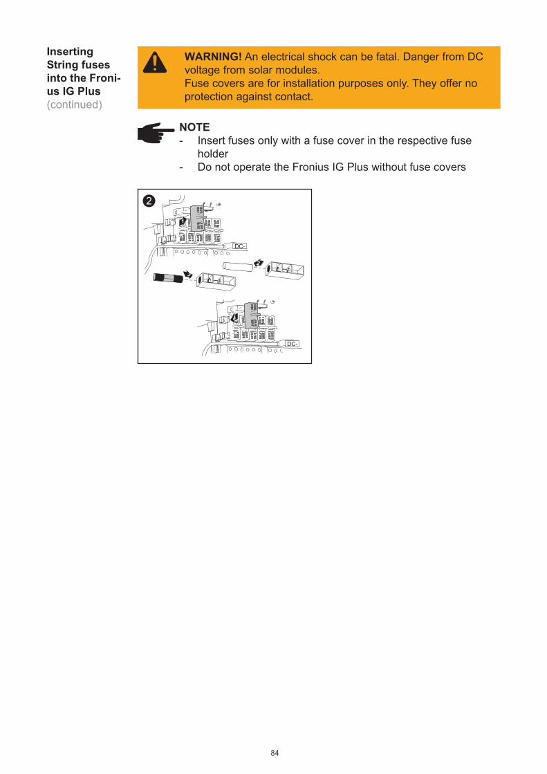
84
InsertingString fusesinto the Froni-us IG Plus(continued)
NOTE- Insert fuses only with a fuse cover in the respective fuse
holder- Do not operate the Fronius IG Plus without fuse covers
1
4
2
3
2
DC-
DC-
WARNING! An electrical shock can be fatal. Danger from DCvoltage from solar modules.Fuse covers are for installation purposes only. They offer noprotection against contact.

85
Criteria for the Proper Selection of String Fuses
Criteria for theProper Selec-tion of StringFuses
The following criteria must be fulfilled for each solar module string whenusing fuse protection:- IN > 1.5 x ISC- IN < 2.00 x ISC- VN >/= 600 V DC- Fuse dimensions: Diameter 10.3 x 35 - 38 mm
IN ....... Nominal current rating of fuseISC ..... short circuit current for standard test conditions (STC) according to
solar module data sheetVN ..... Nominal voltage rating of fuse
NOTE The string fuse size must not be greater than the maxi-mum fuse size rating of the PV module as provided on the PVmodule manufacturers data sheet. If no maximum fuse size isindicated, please contact the PV module manufacturer.
Effects ofusing underra-ted fuses
In underrated fuses, the nominal current value is less than the short circuitcurrent of the solar module.Effect:The fuse may trip in intensive irradiance conditions.
General The use of string fuses in the inverter also adds fuse protection to thesolar modules.A crucial factor for the fuse protection of solar modules is the maximumshort circuit current (ISC) of the respective solar module.
DC disconnectrequirements
NEC 690.15-18 allows the use of fuse holders as a suitable means ofdisconnecting PV arrays for servicing. Additional DC disconnects externalto the inverter may be required by the local authority having jurisdiction.

86
Fuse Recom-mendations -ApplicationExample
NOTEOnly select fuses suitable for a voltage of 600 V DC.
Example:Maximum short circuit current (ISC) of the solar module = 5.75 A
According to the criteria for selecting the correct fuse, the fuse must havea nominal current greater than 1.5 times the short circuit current:5.75 A x 1.5 = 8.625 A
The fuse that should be selected according to the ‘Fuses’ table: KLK D 9with 9.0 A and 600 V AC / DC
Nominal Fusecurrent value
1.0 A KLK D 11.5 A KLK D 1 1/2
2.0 A KLK D 22.5 A KLK D 2 1/2
3.0 A KLK D 33.5 A KLK D 3 1/2
4.0 A KLK D 45.0 A KLK D 5
Fuses
‘Fuses’ table: Excerpt of suitable fuses, e.g. Littelfuse fuses
Nominal Fusecurrent value
6.0 A KLK D 67.0 A KLK D 78.0 A KLK D 89.0 A KLK D 910.0 A KLK D 1012.0 A KLK D 1215.0 A KLK D 1520.0 A KLK D 20

87
Solar Module Ground at Positive Pole: Connec-ting Solar Module Strings
The following steps are necessary when the solar module manufacturerrequires a solar module ground at the positive pole.
General
Solar ModuleGround atPositive Pole
=~
=~
DC+
DC-
Inverter
L1N
GND
Solar module
Solar module ground at positive pole with fuse
DC main switch
GFDI fuse
String fuse
Wire CrossSection ofSolar ModuleStrings
WARNING! An electric shock can be fatal. Normally groundedconductors may be ungrounded and energized when a groundfault is indicated. The ground fault has to be repaired beforeoperation is resumed.
NOTE Do not connect the ground to the DC positive at anypoint! This is already done within the Fronius IG Plus. If the DCpositive is connected to ground at the DC terminal block or prior,this will circumvent the GFDI protection system, preventing yourFronius IG Plus from properly detecting a fault current. Additional-ly, turning the DC disconnect to the off/open-circuit condition willnot disconnect the array from ground, as it only disconnects theDC negative.
WARNING! An electric shock can be fatal. Inadequately sizedelectrical components can cause serious injuries to personsand damage to (or loss of) property.- Electrical installations must be in accordance with the Nati-
onal Electrical Code, ANSI/NFPA 70, and any other codesand regulations applicable to the installation site.
- For installations in Canada the installations must be done inaccordance with applicable Canadian standards.
- Use minimum AWG 10, min. 167 °F (75 °C), copper wire forall grounding wires.
L2
L3

88
3
2
1
2 4
3
45
5
42
1 3
3
4
1
After disconnecting the DC main switch wire:- Connect the DC+ wire to the DC- connection as per step 4- Connect the DC- wire to the DC+ connection as per step 4
NOTEIdentify the reversed polarity accordingly with (+) and (-).
Solar ModuleGround atPositive Pole:ConnectingSolar ModuleStrings
Wire CrossSection ofSolar ModuleStrings(continued)
WARNING! An electric shock can be fatal. Inadequately sizedelectrical components can cause serious injuries to personsand damage to (or loss of) property.- Use minimum AWG 14 to maximum AWG 6, min. 167°F
(75°C), copper wire for all DC wiring connections to theFronius IG Plus. Voltage drop and other considerations maydictate larger size wires be used.
- Use only solid or stranded wire. Do not use fine strandedwire.
NOTE Only use water tight conduit fittings and conduits.Conduit fittings and conduits are not part of the scope of deliveryfor the inverter.
1
1
2
1
Conduit

89
Solar ModuleGround atPositive Pole:ConnectingSolar ModuleStrings(continued)
1
3
5
1/2 in.
2
4
5 4
6
CAUTION! Danger of damaging the inverter by overload.Connect a maximum of 20 A per solar module string to one DCterminal - maximum of 6 solar module strings.
6
2
1
* Wire for solar module grounding
NOTE Connecting theDC wiring with the wrongpolarity may cause dama-ge to the inverter.
Check both the polarity and theopen circuit voltage.
The DC Voltage must not exceed600 V, regardless of temperature.
DC+
7
2
1
DC-
DC+
3
8
2
1
DC-
DC+
NOTEForm a min. 4 in. wire loop using all wires.
Tightening torque:stranded wires ................ 1.25 ft. lb.solid wires ...................... 0.81 ft. lb.
1.33 ft. lb.1.33 ft. lb.
Tightening torque for solid and strandedwires
Tightening torque for solid and strandedwires
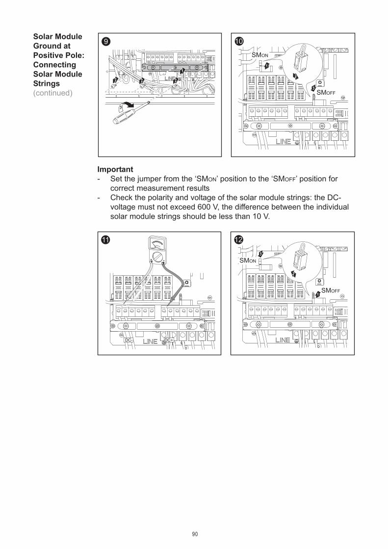
90
11
DC- DC+
10
3
1
2
SMON
SMOFF
12
Solar ModuleGround atPositive Pole:ConnectingSolar ModuleStrings(continued)
9
4
1
2 22
3
3
1
2
10
SMON
SMOFF
Important- Set the jumper from the ‘SMON’ position to the ‘SMOFF’ position for
correct measurement results- Check the polarity and voltage of the solar module strings: the DC-
voltage must not exceed 600 V, the difference between the individualsolar module strings should be less than 10 V.

91
ConnectingGroundingElectrode Wire
If the photovoltaic system requires a grounding electrode, it should beconnected as follows:
1
1
2
2
3
2
1
NOTEForm a min. 4 in. wire loop with the wire.
Important The Fronius IG Plus is shipped with conductive slugs in thefuseholders. Series fusing may be required depending on the type of PVmodule used in the system. See NEC 690.9.
Select string fuses according to the information from the solar modulemanufacturer or as per ‘Criteria for the Proper Selection of StringFuses’ (max. 20 A per solar module string, max. 6 solar modulestrings)
Important- Follow all solar module safety instructions- Follow all solar module manufacturer requirements
Solar ModuleGround atPositive Pole:InsertingString fusesinto the Froni-us IG Plus
1
Tightening torque:stranded wires ................ 1.25 ft. lb.solid wires ...................... 0.81 ft. lb.

92
Solar ModuleGround atPositive Pole:InsertingString fusesinto the Froni-us IG Plus(continued)
NOTE- Insert fuses only with a fuse cover in the respective fuse
holder- Do not operate the Fronius IG Plus without fuse covers
1
4
2
3
2
DC-
DC-
WARNING! An electrical shock can be fatal. Danger from DCvoltage from solar modules.Fuse covers are for installation purposes only. They offer noprotection against contact.

93
Criteria for the Proper Selection of String Fuses
Criteria for theProper Selec-tion of StringFuses
The following criteria must be fulfilled for each solar module string whenusing fuse protection:- IN > 1.5 x ISC- IN < 2.00 x ISC- VN >/= 600 V DC- Fuse dimensions: Diameter 10.3 x 35 - 38 mm
IN ....... Nominal current rating of fuseISC ..... short circuit current for standard test conditions (STC) according to
solar module data sheetUN ..... Nominal voltage rating of fuse
NOTE The string fuse size must not be greater than the maxi-mum fuse size rating of the PV module as provided on the PVmodule manufacturers data sheet. If no maximum fuse size isindicated, please contact the PV module manufacturer.
Effects ofusing underra-ted fuses
In underrated fuses, the nominal current value is less than the short circuitcurrent of the solar module.Effect:The fuse may trip in intensive irradiance conditions.
General The use of string fuses in the inverter also adds fuse protection to thesolar modules.A crucial factor for the fuse protection of solar modules is the maximumshort circuit current (ISC) of the respective solar module.
DC disconnectrequirements
NEC 690.15-18 allows the use of fuse holders as a suitable means ofdisconnecting PV arrays for servicing. Additional DC disconnects externalto the inverter may be required by the local authority having jurisdiction.

94
Fuse Recom-mendations -ApplicationExample
NOTEOnly select fuses suitable for a voltage of 600 V DC.
Example:Maximum short circuit current (ISC) of the solar module = 5.75 A
According to the criteria for selecting the correct fuse, the fuse must havea nominal current greater than 1.5 times the short circuit current:5.75 A x 1.5 = 8.625 A
The fuse that should be selected according to the ‘Fuses’ table: KLK D 9with 9.0 A and 600 V AC / DC
Nominal Fusecurrent value
1.0 A KLK D 11.5 A KLK D 1 1/2
2.0 A KLK D 22.5 A KLK D 2 1/2
3.0 A KLK D 33.5 A KLK D 3 1/2
4.0 A KLK D 45.0 A KLK D 5
Fuses
‘Fuses’ table: Excerpt of suitable fuses, e.g. Littelfuse fuses
Nominal Fusecurrent value
6.0 A KLK D 67.0 A KLK D 78.0 A KLK D 89.0 A KLK D 910.0 A KLK D 1012.0 A KLK D 1215.0 A KLK D 1520.0 A KLK D 20

95
Attaching Power Stage Sets and Closing the Fro-nius IG Plus
Preparation
AttachingPower StageSets AndClosing theFronius IGPlus
1
2
1
2
1
23
54
68
7
1
2
1
2
1 1
2 3
Opening theFronius IGPlus for Ser-vice/Mainten-ance
Procedure for opening the Fronius IG Plus for service or maintenance:
1. Disconnect the AC and DC supply from the inverter2. Open the connection area3. Turn off DC main switch4. Allow the capacitors to discharge (5 minutes)5. Remove metal covers6. Remove the plastic dividers7. Remove string fuses8. Disconnect DC wire9. Disconnect AC wire
The Fronius IG Plus is now operational.

96
Start up Operation
Your Fronius IG Plus unit has been pre-configured in the factory and isready for operation. You only have to set the available power grid forstartup.To change your inverter settings, please see section ‘The Setup Menu’ inthe chapter ‘Operation’.
Factory pre-set configura-tion
Requirementsfor Starting upOperation
- Fronius IG Plus connected to the public grid (AC)- Fronius IG Plus connected to the solar modules (DC)- 3 plastic dividers set in- 2 metal covers mounted- power stage set mounted
NOTEDo not operate the Fronius IG Plus without fuse covers.
Start up Ope-ration 1
off
on1
2
ON1. Turn on AC disconnect2. Flip DC main switch to position
- 1 -
As soon as the photovoltaicmodules produce sufficientpower, the Operating StatusLED lights up orange.
The orange LED indicates thatthe feed-in mode of the FroniusIG Plus will begin shortly.
The screen displays the startupphase
- Segment testAll display elements light upfor about one second
- The Fronius IG Plus unitgoes through a mastercheck list for several se-conds
The display shows ‘TEST’and indicates the respectivecomponent which is beingtested (for example ‘LED’)
AC

97
Start up Opea-tion(continued)
- The grid selection phasebegins: 'SETUPSEL' isshown
3. Press the ‘Enter’ key
The first grid selection option isshown (e.g.: 208 V)
4. Selecting the public grid
Selecting thepublic grid
Several grid selection options are displayed depending on the producttype (see also section 'Connecting the Fronius IG Plus to the PublicGrid’).
1. Use the ‘Up’ and ‘Down’ keys to select the desired grid
Grid voltage 208 V DeltaNo neutral conductor in the systemNeutral conductor monitoring is deactivated
120
° 120 °
120 °
208 V
208 V
208 V
L1
L2L3
=
~
=
~
=
~
120
V
120 V 120 V
120
° 120 °
120 °
208
V 208 V
208 V
L1
L2
N
L3
=
~
=
~
=
~
Grid voltage 208 V Delta: 120 V WYENeutral conductor available in the systemNeutral conductor monitoring is activated

98
Selecting thepublic grid(continued)
Grid voltage 240 V DeltaNo neutral conductor in the systemNeutral conductor monitoring is deactivated
240 V240 V
240 V
120
° 120 °
120 °
L1
L2L3
=
~
=
~
=
~
Grid voltage 240 V: 120 V StingerNeutral conductor available in the systemNeutral conductor monitoring is activated
240 V240
V120
° 120 °
120 °
120 V120 V
L3
L1N
L2
=
~
=
~
=
~
180 °
120 V 120 V
240 V
L1 L2N
=
~
Grid voltage 240 V: 120 V Split PhaseNeutral conductor available in the systemNeutral conductor monitoring is activated
240 V240
V120
° 120 °
120 °
120 V120 V
L3
L1N
L2
=
~
=
~
=
~

99
Selecting thePublic grid(continued)
277
V
277 V 277 V
120
° 120 °
120 °
480
V 480V
480 V
L1
L2
N
L3
=
~
=
~
=
~
Grid voltage 480 V Delta: 277 V WYENeutral conductor available in the systemNeutral conductor monitoring is activated
2. Press the 'Enter' key 2x to confirm your grid selection (or use the 'Esc'key to return to grid selection)
The startup phase starts again with the segment test.
Startup Phaseat StartupOperation
- ‘TESTCOM’ is shown
- Synchronization with grid‘WAITPS’ is shown: The FroniusIG Plus is waiting for all powersupplies in the network to be onstand-by. This procedure takesplace dependent on the DC-voltage.
- Segment testAll display elements light up forabout one second
- The Fronius IG Plus unit goesthrough a master check list forseveral seconds
The display shows ‘TEST’ andindicates the respective compo-nent which is being tested (forexample ‘LED’)

100
- Operation of feeding energyinto the gridAfter conclusion of the tests,the Fronius IG Plus unit startsfeeding energy into the grid.The display shows the presentpower feeding into the grid.The Operating Status LEDlights up green, and the FroniusIG Plus unit starts operating.
Important For more information about the startup phase, please seechapter 'Operation', section 'Product Description Fronius IG Plus' (StartupPhase, Test Procedure).
Startup Phaseat StartupOperation(continued)
Next, the display shows
- Startup testBefore the Fronius IG Plus unitstarts feeding energy into thegrid, the conditions of the gridare tested in detail in accor-dance with regulations.The display shows ‘STARTUP’
‘SYNCAC’, the grid icon blinks

101
Inserting Option Cards
Suitable Opti-on Cards
There are several options and system upgrades available for the FroniusIG Plus, e.g.:- Datalogger and modem interface, Ethernet/Internet connection (for
using a PC to record and manage data from your photovoltaic system)- Various large displays (Fronius Public Display)- Sensors (temperature / irradiance / energy meter, wind speed)- Fronius Personal Display
System upgrades are available as plug-in cards and as external boxes.The Fronius IG Plus 12.0-3 WYE 277 is designed for three option cards,all other Fronius IG Plus products are designed for two option cards.
Safety WARNING! An electrical shock can be fatal. Danger from gridvoltage and DC voltage from solar modules.- The connection area should only be opened by a licensed
electrician.- Never work with live wires! Prior to all connection work,
make sure that the AC and DC wires are not charged.- All electrical installations must be in accordance with the
National Electrical Code, ANSI/NFPA 70, and any othercodes and regulations applicable to the installation site.
- For installations in Canada the installations must be done inaccordance with applicable Canadian standards.
WARNING! An electrical shock can be fatal. Danger fromresidual voltage from capacitors.You must wait until the capacitors have discharged. Dischargetakes 5 minutes.
NOTEFollow general ESD precautions when handling option cards.
Opening theFronius IGPlus
When adding option cards to the Fronius IG Plus, please follow all inver-ter safety instructions and information.

102
Opening Fro-nius IG Plus(continued)
InsertingOption Cards
Insert option cards into free slots.
1
2
1
2
2
3 45
76
8
9
1
Important The plastic dividers are used to separate the data communi-cation wires from the AC and DC wires:- Data communication wires must be laid above the plastic dividers- AC and DC wires are laid under the plastic dividers
Make sure that the plastic dividers are present.
1
1
ConnectingOption Cards,Laying DataCommunicati-on Wires
CAUTION! Danger of short circuit by loose metal parts fromknockouts. Loose metal parts in the inverter may cause shortcircuits when the inverter is powered up. Whenremoving knockouts, make sure that- no loose metal parts fall into the inverter- any metal pieces that do fall into the inverter are removed
immediately

103
2
1
1
1
NOTE The knockout for the data communication wire must beabove the plastic dividers so that the plastic dividers are alwaysunder the data communication wire.
* Position of
ConnectingOption Cards,Laying DataCommunicati-on Wires(continued) *
plastic dividers
NOTE Only use water tight conduit fittings and conduits.Conduit fittings and conduits are not part of the scope of deliveryfor the inverter.
Conduit
3
2
1
2
4
21
1
2
3 = one wire input for both data communication wires
4 = separated wire inputs on opposite sides (e.g. when several invertersare installed next to each other)

104
Closing theFronius IGPlus
Solar Net andData Interface
1
54
3
1
2
87
6
9
2
2
1
Important Secure newly-added option cards to the metal cover usingthe screws provided with the option cards.
Fronius developed Solar Net to make these add-on system componentsflexible and capable of being used in a wide variety of differentapplications. Solar Net is a data network which enables several FroniusIG Plus units to be linked with the system upgrades.Solar Net is a bus system. A single wire is all that is required for one ormore Fronius IG Plus units to communicate with all system upgradecomponents.The core of the Solar Net is the Datalogger. It coordinates datatransmission and ensures quick and safe distribution and storage of largevolumes of data.The ‘Fronius Com Card’ is required to integrate the Fronius IG Plus intothe Solar Net.
Important Every Fronius IG Plus that is to be monitored using a Data-logger requires a ‘Fronius Com Card.’ In this case, the ‘Fronius Com Card’serves as a link between the internal network of the Fronius IG Plus andthe Solar Net interface of the Datalogger.
Important Each inverter can only have one ‘Fronius Com Card.’ A net-work may only contain one Datalogger.The first Fronius IG Plus with a ‘Fronius Com Card’ can be up to 3280 ft(1000 m) away from the last Fronius IG Plus with a ‘fronius Com Card’.Different system upgrades are detected automatically by Solar Net.In order to distinguish between several identical system upgrades, eachone must be assigned a unique number.

105
Solar Net andData Interface(continued)
In order to uniquely define each Fronius IG Plus in Solar Net,each Fronius IG Plus must also be assigned an individual number.You can assign individual numbers as per ‘The Setup Menu’ section inthis manual.More detailed information on the individual system upgrades can be foundin the relevant operating instructions or on the Internet athttp://www.fronius-usa.com.
Example
1 2 3
FroniusIG Plus
FroniusIG Plus
FroniusIG Plus
Com
Car
d
Dat
alog
ger C
.
IN OUT
Com
Car
d
Com
Car
d
IN OUT
RS
232
IN OUT
Sensor Box
IN OUT
°C
W/m²
m/s
PC
Logging and archiving data from the inverter and sensor using a Datalog-ger and sensor box.
Data network with 3 Fronius IG Plus units and one sensor box:- all Fronius IG Plus units have one ‘Fronius Com Card’- one Fronius IG Plus has a ‘Datalogger card’ (no. 2)- Datalogger has two RS-232 interfaces for connecting to a PC and a modem
Termination plug
Option cards communicate within the Fronius IG Plus via its internal net-work. External communication (Solar Net) takes place via the ‘FroniusCom Cards.’ Each ‘Fronius Com Card’ is equipped with two RS485 inter-faces - an input and an output. RJ45 plug connectors are used to connectto these cards.

106
107
Troubleshooting and Maintenance

108

109
Status Diagnosis and Troubleshooting
Your Fronius IG Plus unit is equipped with a self diagnostic system thatautomatically identifies a large number of possible operation issues byitself and displays them on the screen. This enables you to know immedi-ately if there are any malfunctions in the Fronius IG Plus, the photovoltaicsystem or any installation or operating errors.
Whenever the self diagnostic system has identified a particular issue, therespective status code is shown on the screen.
Important Display of a status code for a short time may be the result ofthe control procedures of your Fronius IG Plus unit. If it subsequentlycontinues to operate normally, there has not been a system error.
DisplayingStatus Codes
Normal opera-tion statuscodes
The open-circuit voltage of thesolar modules is too low.
As soon as the open-circuit voltage exceeds 290 V, the Fronius IG Plusunit starts synchronizing with the grid (display shows ‘SYNCAC’).
After a short time the Fronius IG Plus resumes grid synchronization (dis-play shows ‘SYNCAC’).
The total power output of the solarmodules is insufficient.
If the display remains dark after sunrise:
- Check the open-circuit voltage of the solar modules at the connec-tions of the Fronius IG Plus:
Open-circuit voltage < 290 V ... error in the photovoltaic system
Open-circuit voltage > 290 V ... may indicate a basic fault in the Froni-us IG Plus. In this case, notify a Fronius-trained service technician.
Total failure

110
Display in normal operation
Status Codeson Fronius IGPlus withseveral powerstage sets
A special status diagnostic is run if an error occurs in a Fronius IG Pluswith several power stage sets.
It is also possible to call up state messages even if there is no actual errorin existence. This form of status polling may be found in the section ‘TheSetup Menu’.
- The status display of the powerstage sets ’STATEPS’ appears
- Press the ‘Enter’ key
Additional information can befound in ‘The Setup Menu’section, STATEPS’ Menu item
Class 1 StatusCodes
The first reaction of your Fronius IG Plus unit is to disconnect from thegrid. Subsequently, the grid will be checked for the duration of the obser-vation period stipulated. If after the end of this period no further defect isidentified, your Fronius IG Plus unit resumes operating and feeding powerinto the grid.
Status codes of class 1 are typicallytemporary. Their cause lies in thegrid.
When there is an error in one of thetwo power stage sets, the displayflashes between ‘STATE’ and thecorresponding status message(e.g. ‘STATE 515’)
and
‘ENTER’
- Press the ‘Enter’ key twice
111
Important The 2nd position x defines the exact network point for thefollowing status messages:0 = several / all 3 phases1 = L12 = L23 = L3
1x2AC voltage too high
Behavior Grid conditions are thoroughly tested and as soon asthey are again within the permissible range, the Froni-us IG Plus will resume feeding power into the grid.
Remedy Check grid connections and fusesIf this status message keeps recurring, contact yoursystem installer
1x3AC voltage too low
Behavior Grid conditions are thoroughly tested and as soon asthey are again within the permissible range, the Froni-us IG Plus will resume feeding power into the grid.
Remedy Check grid connections and fusesIf this status message keeps recurring, contact yoursystem installer
1x5AC frequency too high
Behavior Grid conditions are thoroughly tested and as soon asthey are again within the permissible range, the Froni-us IG Plus will resume feeding power into the grid.
Remedy Check grid connections and fusesIf this status message keeps recurring, contact yoursystem installer
1x6AC frequency too low
Behavior Grid conditions are thoroughly tested and as soon asthey are again within the permissible range, the Froni-us IG Plus will resume feeding power into the grid.
Remedy Check grid connections and fusesIf this status message keeps recurring, contact yoursystem installer
Class 1 StatusCodes(continued)

112
1x7No grid voltage detected
Behavior As soon as the grid conditions have returned to ad-missible range, Fronius IG Plus resumes feedingpower into the grid
Remedy Check grid connections and fuses;If the status code does not disappear you shouldcontact your electrical contractor
108Islanding detected
Behavior As soon as grid frequency has returned to admissiblerange, Fronius IG Plus resumes feeding power intothe grid
Remedy Check grid voltage;If the status code does not disappear you shouldcontact your electrical contractor
109General grid errorThis error is always displayed first for grid errors. After reviewing all powerstage sets, the grid error is specified with more detail: 1x1 / 1x4 or thedisplay remains at ‘109’ (e.g. when 2 phases report ‘104’ and one phase‘101’)
Behavior Grid conditions are thoroughly tested and as soon asthey are again within the permissible range, the Froni-us IG Plus will resume feeding power into the grid.
Remedy Check grid connections and fusesIf this status message keeps recurring, contact yoursystem installer
The first reaction of your Fronius IG Plus unit is to disconnect from thegrid. Subsequently, the grid will be checked for the duration of the obser-vation period stipulated. If after the end of this period no further defect isidentified, your Fronius IG Plus unit resumes operating and feeding powerinto the grid.
Important The 2nd position x defines the exact network point for thefollowing status messages:0 = several / all 3 phases1 = L12 = L23 = L3
Class 2 StatusCodes
Status codes of class 2 are typicallytemporary. Their cause lies in thegrid.
Class 1 StatusCodes(continued)

113
2x2Grid voltage exceeds admissible limits
Behavior As soon as the grid voltage has returned to admissi-ble range, Fronius IG Plus resumes feeding powerinto the grid
Remedy Check grid voltage; if the status code persists youshould contact your electrical contractor
2x3Grid voltage below admissible limits
Behavior As soon as the grid voltage has returned to admissi-ble range, Fronius IG Plus resumes feeding powerinto the grid
Remedy Check grid voltage, if the status code persists youshould contact your electrical contractor
207No grid voltage detected
Behavior As soon as the grid conditions have returned toadmissible range, Fronius IG Plus resumes feedingpower into the grid
Remedy Check grid connections and fuses; if the status codedoes not disappear you should contact your electricalcontractor
Class 3 StatusCodes
Class 3 comprises status codesthat may appear during operationof feeding power supply, that do notcause a permanent interruption ofthe operation of feeding power intothe grid.
Class 2 StatusCodes(continued)
After automatic disconnection from the grid and waiting for its conditionsto return to those stipulated, your Fronius IG Plus unit will try to resumefeed-in operation.
301Over-current (AC)
Behavior Short interruption of power feeding into the grid,caused by overcurrentFronius IG Plus returnes to startup phase
Remedy automaticallyShould the status code persist, you should contactyour electrical contractor

114
302Over-current (DC)
Behavior Short interruption of power feeding into the grid,caused by overcurrentFronius IG Plus returns to startup phase
Remedy automaticallyShould the status code persist, you should contactyour electrical contractor
303Over-temperature AC side
Behavior Short interruption of power feeding into the gridcaused by overtemperature
Remedy after a two minutes cooling phase your Fronius IGPlus unit restartsShould the status code persist, you should contactyour electrical contractor
304Over-temperature DC-side
Behavior Short interruption of power feeding into the gridcaused by overtemperature
Remedy after a two minutes cooling phase your Fronius IGPlus unit restartsShould the status code persist, you should contactyour electrical contractor
305No power transfer to grid possible
Behavior Continual interruption of grid feed operationRemedy Should the status code persist, you should contact
your electrical contractor‘POWERLOW’ (306)Intermediate circuit voltage has dropped below permissible thresholdvalue for feed in.this error is shown on the Fronius IG Plus in plain text
Behavior Short interruption of power feeding into the gridFronius IG Plus resumes starting up phase
Remedy automaticallyShould the status code persist, you should contactyour electrical contractor
Class 3 StatusCodes(continued)

115
‘DCLOW’ (307)DC-input voltage is too low for feed inthis error is shown on the Fronius IG Plus in plain text
Behavior Short interruption of power feeding into the gridFronius IG Plus resumes starting up phase
Remedy automaticallyShould the status code persist, you should contactyour electrical contractor
Important The status messages 'POWERlow' (306) and 'DClow' (307)occur every morning and evening. No corrective measures are requiredfor these status messages.308Intermediate circuit voltage too high
Behavior Short interruption of power feeding into the gridFronius IG Plus resumes starting up phase
Remedy automaticallyShould the status code persist, you should contactyour electrical contractor
Class 3 StatusCodes(continued)
Class 4 StatusCodes
Class 4 status codes may requirethe intervention of a trained Froniusservice technician.
401No internal communication with power stage
Behavior If it is possible, your Fronius IG Plus unit will resumethe power feeding operation after successfully com-pleting another attempt to connect
Remedy If status code persists, you should contact a Fronius-trained service technician
402Faulty EEPROM access
Behavior If it is possible, your Fronius IG Plus unit will resumethe power feeding operation after successfully com-pleting another attempt to connect
Remedy If status code persists, you should contact a Fronius-trained service technician
116
403EEPROM faulty
Behavior If it is possible, your Fronius IG Plus unit will resumethe power feeding operation after successfully com-pleting another attempt to connect
Remedy If status code persists, you should contact a Fronius-trained service technician
406AC temperature sensor faulty
Behavior Fronius IG Plus disconnects from the grid for safetyreasons
Remedy If status code persists, you should contact a Fronius-trained service technician
407DC temperature sensor faulty
Behavior Fronius IG Plus disconnects from the grid for safetyreasons
Remedy If status code persists, you should contact a Fronius-trained service technician
408Direct current feed in
Behavior Fronius IG Plus disconnects from the grid for safetyreasons
Remedy If status code persists, you should contact a Fronius-trained service technician
412The setting “fixed voltage“ has been selected instead of the MPP-voltageoperation and the voltage is set to too low a value, or DC voltage exceedsallowable limits.
Behavior Fixed voltage lower than the current MPP-voltageRemedy If status code persists, you should contact a Fronius-
trained service technician, or remove excess modulesso DC voltage fits within inverter limits.
413Control problems
Behavior The Fronius IG Plus briefly disconnects from the grid,if AC voltage or frequency are out of range
Remedy If status code persists, you should contact a Fronius-trained service technician
414EEPROM faulty
Behavior Memory deletedRemedy If status code persists, you should contact a Fronius-
trained service technician
Class 4 StatusCodes(continued)

117
416Communication with IG-Brain not possible
Behavior The Operating Status LED lights up orange, then theFronius IG Plus attempts a restart
Remedy If status code persists, contact a Fronius-trainedservice technician
417Two power stage sets have the same PCB number
Behavior The Fronius IG Plus stops feeding power into thegrid, the display shows a critical error via a red Ope-rating Status LED
Remedy If status code persists, contact a Fronius-trainedservice technician
419Two or more power stage sets with an identical software serial numberdetected
Behavior The Fronius IG Plus stops feeding power into thegrid, the display shows a critical error via a red Ope-rating Status LED
Remedy If status code persists, contact a Fronius-trainedservice technician
421PCB number has been set incorrectly
Behavior The Fronius IG Plus stops feeding power into thegrid, the display shows a critical error via a red Ope-rating Status LED
Remedy If status code persists, contact a Fronius-trainedservice technician
425Communication with the power stage set is not possible
Behavior The Operating Status LED lights up orange, then theFronius IG Plus attempts a restart
Remedy If status code persists, contact a Fronius-trainedservice technician
431All power stage sets are in boot mode
Behavior The Fronius IG Plus stops feeding power into thegrid, the display shows a critical error via a red Ope-rating Status LED
Remedy Update firmware using Bootloader or ‘FroniusSolar.update/IG Plus’
Class 4 StatusCodes(continued)

118
Class 4 StatusCodes(continued)
439The MPP master power stage set is switched off because of an error in aslave power stage set (in the balance mode)
Behavior The Fronius IG Plus stops feeding power into thegrid, the display shows a critical error via a red Ope-rating Status LED
Remedy If status code persists, contact a Fronius-trainedservice technician
442No phase master for a phase
Behavior The Fronius IG Plus stops feeding power into thegrid, the display shows a critical error via a red Ope-rating Status LED
Remedy If status code persists, contact a Fronius-trainedservice technician
443Energy transfer not possible
Behavior The Fronius IG Plus stops feeding power into thegrid, the display shows a critical error via a red Ope-rating Status LED
Remedy If status code persists, contact a Fronius-trainedservice technician
445Invalid power stage set configuration
Behavior The Fronius IG Plus stops feeding power into thegrid, the display shows a critical error via a red Ope-rating Status LED
Remedy If status code persists, contact a Fronius-trainedservice technician
446Internal communication error with NL-MON PC board
Behavior If it is possible, your Fronius IG Plus unit will resumethe power feeding operation after successfully com-pleting another attempt to connect
Remedy If status code persists, contact a Fronius-trainedservice technician
447NL-MON PC board stopped grid monitoring
Behavior If it is possible, your Fronius IG Plus unit will resumethe power feeding operation after successfully com-pleting another attempt to connect
Remedy If status code persists, contact a Fronius-trainedservice technician

119
Class 4 StatusCodes(continued)
448N (neutral) conductor not connected
Behavior Fronius IG Plus disconnects from grid for safetyreasons
Remedy Check grid setup, grid connections and fusesIf status code persists, contact your electrical contrac-tor or a Fronius-trained service technician
450The monitoring of the power stage set main processor ‘Guard’ is active
Behavior The Fronius IG Plus stops feeding power into thegrid, the display shows a critical error via a red Ope-rating Status LED
Remedy If status code persists, contact a Fronius-trainedservice technician
451The EEPROM Guard Control is defective
Behavior The Fronius IG Plus stops feeding power into thegrid, the display shows a critical error via a red Ope-rating Status LED
Remedy If status code persists, contact a Fronius-trainedservice technician
452Communication between ‘Guard’ and the digital signal processor (DSP)has been interrupted
Behavior The Fronius IG Plus stops feeding power into thegrid, the display shows a critical error via a red Ope-rating Status LED
Remedy If status code persists, contact a Fronius-trainedservice technician
453Error in grid voltage recording
Behavior The Fronius IG Plus stops feeding power into thegrid, the display shows a critical error via a red Ope-rating Status LED
Remedy If status code persists, contact a Fronius-trainedservice technician
454Error in grid frequency recording
Behavior The Fronius IG Plus stops feeding power into thegrid, the display shows a critical error via a red Ope-rating Status LED
Remedy If status code persists, contact a Fronius-trainedservice technician

120
Class 4 StatusCodes(continued)
455Reference power source for AC measurement is operating outside oftolerances
Behavior The Fronius IG Plus stops feeding power into thegrid, the display shows a critical error via a red Ope-rating Status LED
Remedy If status code persists, contact a Fronius-trainedservice technician
456Error during anti-islanding test
Behavior The Fronius IG Plus stops feeding power into thegrid, the display shows a critical error via a red Ope-rating Status LED
Remedy If status code persists, contact a Fronius-trainedservice technician
457Grid relay stuck
Behavior The Fronius IG Plus stops feeding power into thegrid, the display shows a critical error via a red Ope-rating Status LED
Remedy If status code persists, contact a Fronius-trainedservice technician
460Reference power source for the digital signal processor (DSP) is opera-ting outside of tolerances
Behavior The Fronius IG Plus stops feeding power into thegrid, the display shows a critical error via a red Ope-rating Status LED
Remedy If status code persists, contact a Fronius-trainedservice technician
461Error in DSP data memory
Behavior The Fronius IG Plus stops feeding power into thegrid, the display shows a critical error via a red Ope-rating Status LED
Remedy If status code persists, contact a Fronius-trainedservice technician
464Display errorThe software and/or hardware versions of the display and IG Brain are notcompatible.
Behavior The Fronius IG Plus stops feeding power into thegrid, the display shows a critical error via a red Ope-rating Status LED
Remedy Update firmware using Bootloader or ‘FroniusSolar.update/IG Plus’

121
Class 4 StatusCodes(continued)
465Display errorThe UI command sent from the IG Brain is not recognized by the presentdisplay version.
Behavior The Fronius IG Plus stops feeding power into thegrid, the display shows a critical error via a red Ope-rating Status LED
Remedy If status code persists, contact a Fronius-trainedservice technician
466Display errorThe display was not detected.
Behavior The Fronius IG Plus stops feeding power into thegrid, the display shows a critical error via a red Ope-rating Status LED
Remedy Check the display for damage, connect display, checkribbon wire for damage, check IG Brain for damageIf status code persists, contact a Fronius-trainedservice technician
467The display has not received a start command from the IG Brain for lon-ger than 6 s
Behavior The Fronius IG Plus will automatically attempt toconnect again and, if possible, resume feeding powerinto the grid
Remedy If status code persists, contact a Fronius-trainedservice technician
469Throttle connected to wrong poles
Behavior The Fronius IG Plus stops feeding power into thegrid, the display shows a critical error via a red Ope-rating Status LED
Remedy Properly connect throttleIf status code persists, contact a Fronius-trainedservice technician
470The buck converter relay does not open at high DC voltage
Behavior The Fronius IG Plus stops feeding power into thegrid, the display shows a critical error via a red Ope-rating Status LED
Remedy Check system configurationIf status code persists, contact a Fronius-trainedservice technician
472Ground fault detected
Behavior Inverter is blocked from feeding energy into the gridRemedy Change GFDI fuse

122
Class 5 StatusCodes
Class 5 status codes generally donot impair the operation of feedingpower into the grid. They will bedisplayed until the service code isacknowledged by pressing a key(the Fronius IG Plus unit, however,continues working normally in thebackground)- press any key- error message disappears
501defective fan
Descriptiopn Low power generation because the temperature inthe unit is too high
Remedy If status code persists, contact a Fronius-trainedservice technician
504No Solar Net communication possible
Description Fronius IG Plus address issued twiceRemedy change Fronius IG Plus address (section: ‘The Setup
Menu’)
Description The LocalNet components required are in the FroniusIG Plus unit: still, communication is not presentlypossible
Remedy Status code will disappear after changing the FroniusIG Plus address
505EEPROM faulty
Description Data from the Setup menu are lostRemedy Automatic rectification506EEPROM faulty
Description Data from the "Total" menu is lostRemedy Automatic rectification507EEPROM faulty
Description Data from the menu ‘Day’ / ‘Year’ is lostRemedy Automatic rectification508Fronius IG Plus address is faulty
Description Address for data communication is no longer savedRemedy Set address again

123
Class 5 StatusCodes(continued)
50924h no feed in
Description e.g. solar modules covered in snowRemedy e.g. remove snow from solar modules
check wiring, DC disconnect, fuses, etc.510EEPROM faulty
Description SMS settings were restored to standardRemedy If necessary, reconfigure SMS511EEPROM faulty
Description Sensor card settings were restored to standardRemedy If necessary, reconfigure metering channels512Too many power stage sets in the system
Description Too many power stage sets have been detected inthe system
Remedy If Service-Code persists, contact a Fronius-trainedservice technician
513Power stage set in boot mode
Description One or more power stage sets cannot be activatedbecause they are in boot mode.
Remedy Update power stage set firmware514No communication with one of the power stage sets
Description Warning message from one of the power stage sets,second power stage set working normally
Remedy If Service-Code persists, contact a Fronius-trainedservice technician
515One or more power stage sets notified a STATE 406 / 407 / 409 / 410
Description Temperature sensor on PINCI PC board faulty or notconnected properly
Remedy Check temperature sensor on PINCI PC boardIf Service-Code persists, contact a Fronius-trainedservice technician
516Status codes present for one of the power stage sets
Description It is not possible to activate all power stage setsRemedy Carry out analysis. Please see section entitled „The
Setup Menu“ and „State_PS“ for further details. IfService-Code persists, contact a Fronius-trainedservice technician

124
Class 5 StatusCodes(continued)
Important Please contact your Fronius dealer or a Fronius-trained ser-vice partner if- an error appears frequently or for a long period of time- an error appears that is not listed in the tables
CustomerService
517Change of master has taken place
Description Transformer not connected / not plugged inBridge short-circuitDetection of intermediate circuit voltage damaged
Remedy Check possible errors referred to in ‘Description’. IfService-Code persists, contact a Fronius-trainedservice technician
550String fuse defective
Description One or more string fuses are defectiveRemedy Measure string fuses and replace any that are defec-
tive550Jumper set incorrectly
Description The jumper on the Print C-Box was not reset to the‘SMON’ position after the solar module strings werechecked
Remedy Set the jumper on the Print C-Box to the ‘SMON’ posi-tion
553Phase master deactivated due to frequently occurring errors
Description A reintegration of the power stage set into the Mixnetwork is being attempted at a later time
Remedy automatically by itself; If Service-Code persists,contact a Fronius-trained service technician
554NL-Mon EEPROM error
Description Default set switch off limits were restored automati-cally
Remedy System depending changes in the service menu‘Advanced’ have to be done again;If Service-Code persists, contact a Fronius-trainedservice technician

125
The Fronius IG Plus is designed so that it does not require additionalmaintenance.However, there are a few points to keep in mind during operation to ensu-re that the inverter functions optimally.
Maintenance
Safety
General
WARNING! An electrical shock can be fatal. Danger fromresidual voltage from capacitors.You must wait until the capacitors have discharged. Dischargetakes 5 minutes.
WARNING! An electrical shock can be fatal. Danger from gridvoltage and DC voltage from solar modules.- The connection area should only be opened by a licensed
electrician.- The separate power stage set area should only be discon-
nected from the connection area after first being discon-nected from the grid power.
- The separate power stage set area should only be openedby Fronius-trained service personnel.
Never work with live wires! Prior to all connection work, makesure that the AC and DC wires are not charged.
The DC main switch is only used to switch off power to thepower stage set. When the DC main switch is turned off, theconnection area is still energized.
These servicing instructions are for use by qualified personnelonly. To reduce the risk of electric shock, do not perform anyservicing other than that specified in the operating instructions.

126
Opening Fro-nius IG Plusfor Service/Maintenance
Procedure for opening the Fronius IG Plus for service or maintenance:
1. Disconnect the AC and DC supply from the inverter2. Open the connection area3. Turn off DC main switch4. Allow the capacitors to discharge (5 minutes)5. Remove metal covers6. Remove the plastic dividers7. Remove string fuses8. Disconnect DC wire9. Disconnect AC wire
When operating the inverter inextremely dusty environments:Remove the fan cover and cleanthe integrated fly screen as re-quired
Operation inDusty Envi-ronments
2
1
3

127
Preparation NOTEDisconnected AC and DC supply from the inverter.
1
2
1
2
2
3 45
76
8
9
1
Replacing String Fuses
Safety
WARNING! An electrical shock can be fatal. Danger fromresidual voltage from capacitors.You must wait until the capacitors have discharged. Dischargetakes 5 minutes.
WARNING! An electrical shock can be fatal. Danger from gridvoltage and DC voltage from solar modules.- The connection area should only be opened by a licensed
electrician.- Never work with live wires! Prior to all connection work,
make sure that the AC and DC wires are not charged.- The DC main switch is only used to switch off power to the
power stage set. When the DC main switch is turned off,the connection area is still energized.
These servicing instructions are for use by qualified personnelonly. To reduce the risk of electric shock, do not perform anyservicing other than that specified in the operating instructions.
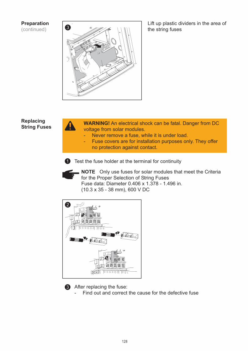
128
Lift up plastic dividers in the area ofthe string fuses
Preparation(continued)
After replacing the fuse:- Find out and correct the cause for the defective fuse
4
2
3
2
1
DC+
3
ReplacingString Fuses
NOTE Only use fuses for solar modules that meet the Criteriafor the Proper Selection of String Fuses
Test the fuse holder at the terminal for continuity1
WARNING! An electrical shock can be fatal. Danger from DCvoltage from solar modules.- Never remove a fuse, while it is under load.- Fuse covers are for installation purposes only. They offer
no protection against contact.
3
1
Fuse data: Diameter 0.406 x 1.378 - 1.496 in.(10.3 x 35 - 38 mm), 600 V DC

129
Closing Froni-us IG Plus 1
1
Return plastic dividers to theirproper position
Important Make sure that theplastic dividers are underneath anydata communication wires that arepresent.
3
2
1
1
54
3
1
2
87
6
9
2

130
Replacing GFDI Fuse
Safety
Preparation
WARNING! An electrical shock can be fatal. Danger fromresidual voltage from capacitors.You must wait until the capacitors have discharged. Dischargetakes 5 minutes.
WARNING! An electrical shock can be fatal. Danger from gridvoltage and DC voltage from solar modules.- The connection area should only be opened by a licensed
electrician.- Never work with live wires! Prior to all connection work,
make sure that the AC and DC wires are not charged.- The DC main switch is only used to switch off power to the
power stage set. When the DC main switch is turned off,the connection area is still energized.
These servicing instructions are for use by qualified personnelonly. To reduce the risk of electric shock, do not perform anyservicing other than that specified in the operating instructions.
NOTEDisconnected AC and DC supply from the inverter.
1
2
1
2
2
3 45
76
8
9
1
WARNING! An electric shock can be fatal. Normally groundedconductors may be ungrounded and energized when a groundfault is indicated. The ground fault has to be repaired beforeoperation is resumed.
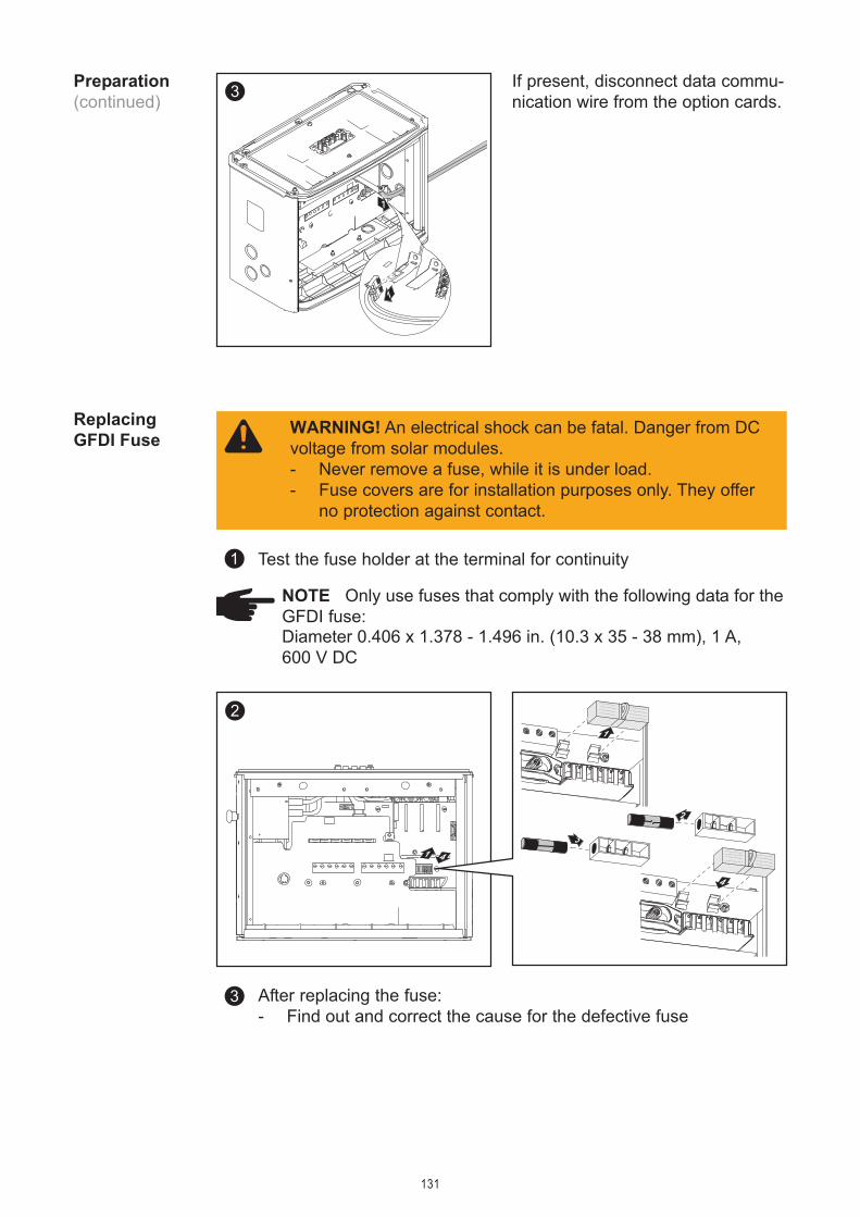
131
If present, disconnect data commu-nication wire from the option cards.
Preparation(continued)
After replacing the fuse:- Find out and correct the cause for the defective fuse
3
ReplacingGFDI Fuse
NOTE Only use fuses that comply with the following data for theGFDI fuse:
Test the fuse holder at the terminal for continuity1
WARNING! An electrical shock can be fatal. Danger from DCvoltage from solar modules.- Never remove a fuse, while it is under load.- Fuse covers are for installation purposes only. They offer
no protection against contact.
3
1
1
2
41
4
1
2
3
Diameter 0.406 x 1.378 - 1.496 in. (10.3 x 35 - 38 mm), 1 A,600 V DC
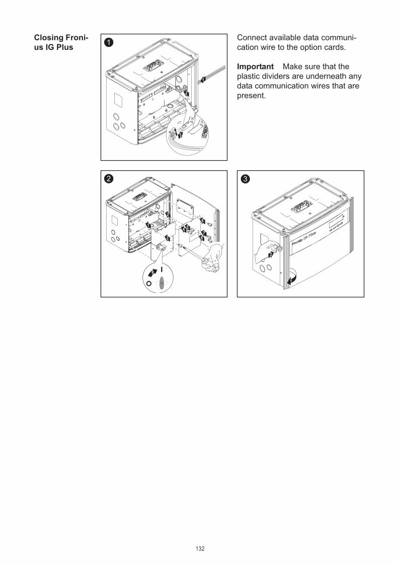
132
Closing Froni-us IG Plus
Connect available data communi-cation wire to the option cards.
Important Make sure that theplastic dividers are underneath anydata communication wires that arepresent.
3
2
1
1
54
3
1
2
87
6
9
2
3
2
1
2
1

133
Appendix

134

135
Technical Data
Fronius IGPlus 3.0-1
Input data
Recommended PV power 2500 - 3450 WpMPPT-voltage range 230 - 500 V DCMax. input voltage 600 V DC(at 1000 W/m² / 14 °F in open circuit operation)Nominal input voltage 390 VNominal input current 8.3 AMaximum usable input current 14 AMax. array short circuit current 18 A
Output data
Nominal output power (Pnom) 3000 WPnom at +122 °F (50 °C) 3000 WMaximum continuous output power 3000 WNominal AC output voltage 208 V / 240 V / 277 V (-12 / +10 %)Operating AC voltage range default at 208 V 183 - 229 V
at 240 V 211 - 264 Vat 277 V 244 - 305 V
Adjustment range for voltage at 208 V 105 - 248 Vat 240 V 120 - 287 Vat 277 V 140 - 324 V
Voltage trip limit accuracy 1 % of nominal valueVoltage clearing times 0.016 - 4.25 sNominal output current at 208 V 14.4 A AC
at 240 V 12.5 A ACat 277 V 10.8 A AC
Number of phases 1Maximum output current at 208 V 16.4 A
at 240 V 14.2 Aat 277 V 12.3 A
Maximum continuous utility backfeed current * 0 ASynchronization in-rush current * 0 AMaximum output fault current / duration 222 A / 47 µsNominal output frequency 60 HzOperating frequency range 59.3 - 60.5 HzAdjustment range for frequency 57.0 - 60.48 Hz

136
Fronius IGPlus 3.0-1(continued)
Frequency trip limit accuracy 0.05 HzFrequency clearing times 0.016 - 300 sTotal harmonic distortion < 3 %Power factor 1
* assured by electrical design of the inverter.
General data
Maximum efficiency 96.2 %CEC efficiency at 208 V 95.0 %
at 240 V 95.5 %at 277 V 95.5 %
Consumption in standby (night) < 1 WConsumption during operation 8 WCooling controlled forced ventilationProtection type NEMA 3RUnit dimensions (w x h x d) 24.84 x 17.09 x 9.61 in.
631 x 434 x 244 mmInverter weight 31 lbs.
14 kgWiring compartment weight 24 lbs.
11 kgShipping dimensions (w x h x d) 31.02 x 20.28 x 14.02 in.
788 x 515 x 356 mmShipping weight 59 lbs.
27 kgAdmissible ambient temperature -4 °F - +122 °F(with 95% rel. humidity) -20 °C - +50 °CAdmissible storage temperature -4 °F - +140 °F(with 95% rel. humidity) -20 °C - +60 °C
Protection devices
Ground fault protection internal GFDI (Ground Fault Detector/Interruptor)Islanding protection internalDC reverse polarity protection internal diodeOver temperature output power derating / active cooling

137
Fronius IGPlus 3.8-1
Input data
Recommended PV power 3200 - 4400 WpMPPT-voltage range 230 - 500 V DCMax. input voltage 600 V DC(at 1000 W/m² / 14 °F in open circuit operation)Nominal input voltage 390 VNominal input current 10.5 AMaximum usable input current 17.8 AMax. array short circuit current 22 A
Output data
Nominal output power (Pnom) 3800 WPnom at +122 °F (50 °C) 3800 WMaximum continuous output power 3800 WNominal AC output voltage 208 V / 240 V / 277 V (-12 / +10 %)Operating AC voltage range default at 208 V 183 - 229 V
at 240 V 211 - 264 Vat 277 V 244 - 305 V
Adjustment range for voltage at 208 V 105 - 248 Vat 240 V 120 - 287 Vat 277 V 140 - 324 V
Voltage trip limit accuracy 1 % of nominal valueVoltage clearing times 0.016 - 4.25 sNominal output current at 208 V 18.3 A AC
at 240 V 15.8 A ACat 277 V 13.7 A AC
Number of phases 1Maximum output current at 208 V 18.5 A
at 240 V 18.0 Aat 277 V 15.6 A
Maximum continuous utility backfeed current * 0 ASynchronization in-rush current * 0 AMaximum output fault current / duration 222 A / 47 µsNominal output frequency 60 HzOperating frequency range 59.3 - 60.5 HzAdjustment range for frequency 57.0 - 60.48 Hz

138
Fronius IGPlus 3.8-1(continued)
Frequency trip limit accuracy 0.05 HzFrequency clearing times 0.016 - 300 sTotal harmonic distortion < 3 %Power factor 1
* assured by electrical design of the inverter.
General data
Maximum efficiency 96.2 %CEC efficiency at 208 V 95.0 %
at 240 V 95.5 %at 277 V 95.5 %
Consumption in standby (night) < 1 WConsumption during operation 8 WCooling controlled forced ventilationProtection type NEMA 3RUnit dimensions (w x h x d) 48.07 x 17.09 x 9.61 in.
1221 x 434 x 244 mmInverter weight 82 lbs.
37 kgWiring compartment weight 26 lbs.
12 kgShipping dimensions 42.72 x 20.28 x 14.02 in. + 17.72 x 20.28 x 14.02 in.(w x h x d) 1085 x 515 x 356 mm + 450 x 515 x 356 mmShipping weight 114 lbs.
52 kgAdmissible ambient temperature -4 °F - +122 °F(with 95% rel. humidity) -20 °C - +50 °CAdmissible storage temperature -4 °F - +140 °F(with 95% rel. humidity) -20 °C - +60 °C
Protection devices
Ground fault protection internal GFDI (Ground Fault Detector/Interruptor)Islanding protection internalDC reverse polarity protection internal diodeOver temperature output power derating / active cooling

139
Fronius IGPlus 5.0-1
Input data
Recommended PV power 4250 - 5750 WpMPPT-voltage range 230 - 500 V DCMax. input voltage 600 V DC(at 1000 W/m² / 14 °F in open circuit operation)Nominal input voltage 390 VNominal input current 13.8 AMaximum usable input current 23.4 AMax. array short circuit current 29 A
Output data
Nominal output power (Pnom) 5000 WPnom at +122 °F (50 °C) 5000 WMaximum continuous output power 5000 WNominal AC output voltage 208 V / 240 V / 277 V (-12 / +10 %)Operating AC voltage range default at 208 V 183 - 229 V
at 240 V 211 - 264 Vat 277 V 244 - 305 V
Adjustment range for voltage at 208 V 105 - 248 Vat 240 V 121 - 287 Vat 277 V 140 - 324 V
Voltage trip limit accuracy 1 % of naminal valueVoltage clearing times 0.016 - 4.25 sNominal output current at 208 V 24.0 A AC
at 240 V 20.8 A ACat 277 V 18.1 A AC
Number of phases 1Maximum output current at 208 V 27.3 A
at 240 V 23.7 Aat 277 V 20.5 A
Maximum continuous utility backfeed current * 0 ASynchronization in-rush current * 0 AMaximum output fault current / duration 273 A / 72 µsNominal output frequency 60 HzOperating frequency range 59.3 - 60.5 HzAdjustment range for frequency 57.0 - 60.48 Hz

140
Fronius IGPlus 5.0-1(continued)
Frequency trip limit accuracy 0.05 HzFrequency clearing times 0.016 - 300 sTotal harmonic distortion < 3 %Power factor 1
* assured by electrical design of the inverter.
General data
Maximum efficiency 96.2 %CEC efficiency at 208 V 95.5 %
at 240 V 95.5 %at 277 V 96.0 %
Consumption in standby (night) < 1 WConsumption during operation 15 WCooling controlled forced ventilationProtection type NEMA 3RUnit dimensions (w x h x d) 36.46 x 17.09 x 9.61 in.
926 x 434 x 244 mmInverter weight 57 lbs.
4 kgWiring compartment weight 24 bs.
11 kgShipping dimensions (w x h x d) 42.72 x 20.28 x 14.02 in.
1085 x 515 x 356 mmShipping weight 90 lbs.
41 kgAdmissible ambient temperature -4 °F - +122 °F(with 95% rel. humidity) -20 °C - +50 °CAdmissible storage temperature -4 °F - +140 °F(with 95% rel. humidity) -20 °C - +60 °C
Protection devices
Ground fault protection internal GFDI (Ground Fault Detector/Interruptor)Islanding protection internalDC reverse polarity protection internal diodeOver temperature output power derating / active cooling

141
Fronius IGPlus 6.0-1
Input data
Recommended PV power 5100 - 6900 WpMPPT-voltage range 230 - 500 V DCMax. input voltage 600 V DC(at 1000 W/m² / 14 °F in open circuit operation)Nominal input voltage 390 VNominal input current 16.6 AMaximum usable input current 28.1 AMax. array short circuit current 35 A
Output data
Nominal output power (Pnom) 6000 WPnom at +122 °F (50 °C) 6000 WMaximum continuous output power 6000 WNominal AC output voltage 208 V / 240 V / 277 V (-12 / +10 %)Operating AC voltage range default at 208 V 183 - 229 V
at 240 V 211 - 264 Vat 277 V 244 - 305 V
Adjustment range for voltage at 208 V 105 - 248 Vat 240 V 121 - 287 Vat 277 V 140 - 324 V
Voltage trip limit accuracy 1 % of nominal valueVoltage clearing times 0.016 - 4.25 sNominal output current at 208 V 28.8 A AC
at 240 V 25.0 A ACat 277 V 21.7 A AC
Number of phases 1Maximum output current at 208 V 32.8 A
at 240 V 28.4 Aat 277 V 24.6 A
Maximum continuous utility backfeed current * 0 ASynchronization in-rush current * 0 AMaximum output fault current / duration 273 A / 72 µsNominal output frequency 60 HzOperating frequency range 59.3 - 60.5 HzAdjustment range for frequency 57.0 - 60.48 Hz

142
Fronius IGPlus 6.0-1(continued)
Frequency trip limit accuracy 0.05 HzFrequency clearing times 0.016 - 300 sTotal harmonic distortion < 3 %Power factor 1
* assured by electrical design of the inverter.
General data
Maximum efficiency 96.2 %CEC efficiency at 208 V 95.5 %
at 240 V 96.0 %at 277 V 96.0 %
Consumption in standby (night) < 1 WConsumption during operation 15 WCooling controlled forced ventilationProtection type NEMA 3RUnit dimensions (w x h x d) 36.46 x 17.09 x 9.61 in.
926 x 434 x 244 mmInverter weight 57 lbs.
26 kgWiring compartment weight 26 lbs.
12 kgShipping dimensions (w x h x d) 42.72 x 20.28 x 14.02 in.
1085 x 515 x 356 mmShipping weight 90 lbs.
41 kgAdmissible ambient temperature -4 °F - +122 °F(with 95% rel. humidity) -20 °C - +50 °CAdmissible storage temperature -4 °F - +140 °F(with 95% rel. humidity) -20 °C - +60 °C
Protection devices
Ground fault protection internal GFDI (Ground Fault Detector/Interruptor)Islanding protection internalDC reverse polarity protection internal diodeOver temperature output power derating / active cooling

143
Fronius IGPlus 7.5-1
Input data
Recommended PV power 6350 - 8600 WpMPPT-voltage range 230 - 500 V DCMax. input voltage 600 V DC(at 1000 W/m² / 14 °F in open circuit operation)Nominal input voltage 390 VNominal input current 20.7 AMaximum usable input current 35.1 AMax. array short circuit current 44 A
Output data
Nominal output power (Pnom) 7500 WPnom at +122 °F (50 °C) 7500 W (6800 W at 208 V)Maximum continuous output power 7500 WNominal AC output voltage 208 V / 240 V / 277 V (-12 / +10 %)Operating AC voltage range default at 208 V 183 - 229 V
at 240 V 211 - 264 Vat 277 V 244 - 305 V
Adjustment range for voltage at 208 V 105 - 248 Vat 240 V 121 - 287 Vat 277 V 140 - 324 V
Voltage trip limit accuracy 1 % of nominal valueVoltage clearing times 0.016 - 4.25 sNominal output current at 208 V 36.1 A AC
at 240 V 31.3 A ACat 277 V 27.1 A AC
Number of phases 1Maximum output current at 208 V 37.0 A
at 240 V 35.5 Aat 277 V 30.7 A
Maximum continuous utility backfeed current * 0 ASynchronization in-rush current * 0 AMaximum output fault current / duration 273 A / 72 µsNominal output frequency 60 HzOperating frequency range 59.3 - 60.5 HzAdjustment range for frequency 57.0 - 60.48 Hz

144
Fronius IGPlus 7.5-1(continued)
Frequency trip limit accuracy 0.05 HzFrequency clearing times 0.016 - 300 sTotal harmonic distortion < 3 %Power factor 1
* assured by electrical design of the inverter.
General data
Maximum efficiency 96.2 %CEC efficiency at 208 V 95.0 %
at 240 V 95.5 %at 277 V 96.0 %
Consumption in standby (night) < 1 WConsumption during operation 15 WCooling controlled forced ventilationProtection type NEMA 3RUnit dimensions (w x h x d) 36.46 x 17.09 x 9.61 in.
926 x 434 x 244 mmInverter weight 57 lbs.
26 kgWiring compartment weight 26 lbs.
12 kgShipping dimensions (w x h x d) 42.72 x 20.28 x 14.02 in.
1085 x 515 x 356 mmShipping weight 90 lbs.
41 kgAdmissible ambient temperature -4 °F - +122 °F(with 95% rel. humidity) -20 °C - +50 °CAdmissible storage temperature -4 °F - +140 °F(with 95% rel. humidity) -20 °C - +60 °C
Protection devices
Ground fault protection internal GFDI (Ground Fault Detector/Interruptor)Islanding protection internalDC reverse polarity protection internal diodeOver temperature output power derating / active cooling

145
Fronius IGPlus 10.0-1
Input data
Recommended PV power 8500 - 11500 WpMPPT-voltage range 230 - 500 V DCMax. input voltage 600 V DC(at 1000 W/m² / 14 °F in open circuit operation)Nominal input voltage 390 VNominal input current 27.6 AMaximum usable input current 46.7 AMax. array short circuit current 58 A
Output data
Nominal output power (Pnom) 9995 WPnom at +122 °F (50 °C) 9995 WMaximum continuous output power 9995 WNominal AC output voltage 208 V / 240 V / 277 V (-12 / +10 %)Operating AC voltage range default at 208 V 183 - 229 V
at 240 V 211 - 264 Vat 277 V 244 - 305 V
Adjustment range for voltage at 208 V 105 - 248 Vat 240 V 121 - 287 Vat 277 V 140 - 324 V
Voltage trip limit accuracy 1 % of nominal valueVoltage clearing times 0.016 - 4.25 sNominal output current at 208 V 48.1 A AC
at 240 V 41.7 A ACat 277 V 36.1 A AC
Number of phases 1Maximum output current at 208 V 54.6 A
at 240 V 47.4 Aat 277 V 40.9 A
Maximum continuous utility backfeed current * 0 ASynchronization in-rush current * 0 AMaximum output fault current / duration 586 A / 104 µsNominal output frequency 60 HzOperating frequency range 59.3 - 60.5 HzAdjustment range for frequency 57.0 - 60.48 Hz

146
Fronius IGPlus 10.0-1(continued)
Frequency trip limit accuracy 0.05 HzFrequency clearing times 0.016 - 300 sTotal harmonic distortion < 3 %Power factor 1
* assured by electrical design of the inverter.
General data
Maximum efficiency 96.2 %CEC efficiency at 208 V 95.0 %
at 240 V 95.5 %at 277 V 96.0 %
Consumption in standby (night) < 1 WConsumption during operation 22 WCooling controlled forced ventilationProtection type NEMA 3RUnit dimensions (w x h x d) 48.07 x 17.09 x 9.61 in.
1221 x 434 x 244 mmInverter weight 82 lbs.
37 kgWiring compartment weight 26 lbs.
12 kgShipping dimensions 42.72 x 20.28 x 14.02 in. + 17.72 x 20.28 x 14.02 in.(w x h x d) 1085 x 515 x 356 mm + 450 x 515 x 356 mmShipping weight 114 lbs.
52 kgAdmissible ambient temperature -4 °F - +122 °F(with 95% rel. humidity) -20 °C - +50 °CAdmissible storage temperature -4 °F - +140 °F(with 95% rel. humidity) -20 °C - +60 °C
Protection devices
Ground fault protection internal GFDI (Ground Fault Detector/Interruptor)Islanding protection internalDC reverse polarity protection internal diodeOver temperature output power derating / active cooling

147
Fronius IGPlus 11.4-1
Input data
Recommended PV power 9700 - 13100 WpMPPT-voltage range 230 - 500 V DCMax. input voltage 600 V DC(at 1000 W/m² / 14 °F in open circuit operation)Nominal input voltage 390 VNominal input current 31.4 AMaximum usable input current 53.3 AMax. array short circuit current 67 A
Output data
Nominal output power (Pnom) 11400 WPnom at +122 °F (50 °C) 11400 W (10800 W at 208 V)Maximum continuous output power 11400 WNominal AC output voltage 208 V / 240 V / 277 VOperating AC voltage range default at 208 V 183 - 229 V
at 240 V 211 - 264 Vat 277 V 244 - 305 V
Adjustment range for voltage at 208 V 105 - 248 Vat 240 V 121 - 287 Vat 277 V 140 - 324 V
Voltage trip limit accuracy 1 % of nominal valueVoltage clearing times 0.016 - 4.25 sNominal output current at 208 V 54.8 A AC
at 240 V 47.5 A ACat 277 V 41.2 A AC
Number of phases 1Maximum output current at 208 V 55.5 A
at 240 V 54.0 Aat 277 V 46.7 A
Maximum continuous utility backfeed current * 0 ASynchronization in-rush current * 0 AMaximum output fault current / duration 586 A / 104 µsNominal output frequency 60 HzOperating frequency range 59.3 - 60.5 HzAdjustment range for frequency 57.0 - 60.48 Hz

148
Fronius IGPlus 11.4-1(continued)
Frequency trip limit accuracy 0.05 HzFrequency clearing times 0.016 -300 sTotal harmonic distortion < 3 %Power factor 1
* assured by electrical design of the inverter.
General data
Maximum efficiency 96.2 %CEC efficiency at 208 V 95.5 %
at 240 V 96.0 %at 277 V 96.0 %
Consumption in standby (night) < 1 WConsumption during operation 22 WCooling controlled forced ventilationProtection type NEMA 3RUnit dimensions (w x h x d) 48.07 x 17.09 x 9.61 in.
1221 x 434 x 244 mmInverter weight 82 lbs.
37 kgWiring compartment weight 26 lbs.
12 kgShipping dimensions 42.72 x 20.28 x 14.02 in. + 17.72 x 20.28 x 14.02 in.(w x h x d) 1085 x 515 x 356 mm + 450 x 515 x 356 mmShipping weight 114 lbs.
52 kgAdmissible ambient temperature -4 °F - +122 °F(with 95% rel. humidity) -20 °C - +50 °CAdmissible storage temperature -4 °F - +140 °F(with 95% rel. humidity) -20 °C - +60 °C
Protection devices
Ground fault protection internal GFDI (Ground Fault Detector/Interruptor)Islanding protection internalDC reverse polarity protection internal diodeOver temperature output power derating / active cooling

149
Fronius IGPlus 11.4-3
Input data
Recommended PV power 9700 - 13100 WpMPPT-voltage range 230 - 500 V DCMax. input voltage 600 V DC(at 1000 W/m² / 14 °F in open circuit operation)Nominal input voltage 390 VNominal input current 31.4 AMaximum usable input current 53.3 AMax. array short circuit current 67 A
Output data
Nominal output power (Pnom) 11400 WPnom at +122 °F (50 °C) 11400 W (10800 W at 208 V)Maximum continuous output power 11400 WNominal AC output voltage 208 V / 240 VOperating AC voltage range default at 208 V 183 - 229 V
at 240 V 211 - 264 VAdjustment range for voltage at 208 V 105 - 248 V
at 240 V 121 - 287 VVoltage trip limit accuracy 1 % of nominal valueVoltage clearing times 0.016 - 4.25 sNominal output current at 208 V 31.6 A AC
at 240 V 27.4 A ACNumber of phases 3Maximum output current at 208 V 32.0 A
at 240 V 31.2 AMaximum continuous utility backfeed current * 0 ASynchronization in-rush current * 0 AMaximum output fault current / duration 476 A / 623 µsNominal output frequency 60 HzOperating frequency range 59.3 - 60.5 HzAdjustment range for frequency 57.0 - 60.48 Hz
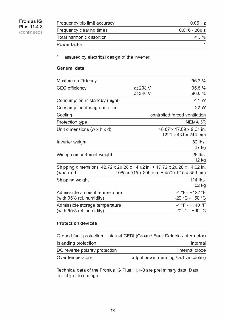
150
Fronius IGPlus 11.4-3(continued)
Frequency trip limit accuracy 0.05 HzFrequency clearing times 0.016 - 300 sTotal harmonic distortion < 3 %Power factor 1
* assured by electrical design of the inverter.
General data
Maximum efficiency 96.2 %CEC efficiency at 208 V 95.5 %
at 240 V 96.0 %Consumption in standby (night) < 1 WConsumption during operation 22 WCooling controlled forced ventilationProtection type NEMA 3RUnit dimensions (w x h x d) 48.07 x 17.09 x 9.61 in.
1221 x 434 x 244 mmInverter weight 82 lbs.
37 kgWiring compartment weight 26 lbs.
12 kgShipping dimensions 42.72 x 20.28 x 14.02 in. + 17.72 x 20.28 x 14.02 in.(w x h x d) 1085 x 515 x 356 mm + 450 x 515 x 356 mmShipping weight 114 lbs.
52 kgAdmissible ambient temperature -4 °F - +122 °F(with 95% rel. humidity) -20 °C - +50 °CAdmissible storage temperature -4 °F - +140 °F(with 95% rel. humidity) -20 °C - +60 °C
Protection devices
Ground fault protection internal GFDI (Ground Fault Detector/Interruptor)Islanding protection internalDC reverse polarity protection internal diodeOver temperature output power derating / active cooling
Technical data of the Fronius IG Plus 11.4-3 are preliminary data. Dataare object to change.

151
Fronius IGPlus 12.0-3
Input data
Recommended PV power 10200 - 13800 WpMPPT-voltage range 230 - 500 V DCMax. input voltage 600 V DC(at 1000 W/m² / 14 °F in open circuit operation)Nominal input voltage 390 VNominal input current 33.1 AMaximum usable input current 56.1 AMax. array short circuit current 70 A
Output data
Nominal output power (Pnom) 12000 WPnom at +122 °F (50 °C) 12000 WMaximum continuous output power 12000 WNominal AC output voltage 277 VOperating AC voltage range default at 277 V 244 - 305 VAdjustment range for voltage at 277 V 140 - 324 VVoltage trip limit accuracy 1 % of nominal valueVoltage clearing times 0.016 - 4.25 sNominal output current at 277 V 14.4 ANumber of phases 3Maximum output current at 277 V 16.4 AMaximum continuous utility backfeed current * 0 ASynchronization in-rush current * 0 AMaximum output fault current / duration 777 A / 163 µsNominal output frequency 60 HzOperating frequency range 59.3 - 60.5 HzAdjustment range for frequency 57.0 - 60.48 Hz

152
Fronius IGPlus 12.0-3(continued)
Frequency trip limit accuracy 0.05 HzFrequency clearing times 0.016 - 300 sTotal harmonic distortion < 3 %Power factor 1
* assured by electrical design of the inverter.
General data
Maximum efficiency 96.2 %CEC efficiency at 277 V 96.0 %Consumption in standby (night) < 1 WConsumption during operation 22 WCooling controlled forced ventilationProtection type NEMA 3RUnit dimensions (w x h x d) 48.07 x 17.09 x 9.61 in.
1221 x 434 x 244 mmInverter weight 82 lbs.
37 kgWiring compartment weight 26 lbs.
12 kgShipping dimensions 42.72 x 20.28 x 14.02 in. + 17.72 x 20.28 x 14.02 in.(w x h x d) 1085 x 515 x 356 mm + 450 x 515 x 356 mmShipping weight 114 lbs.
52 kgAdmissible ambient temperature -4 °F - +122 °F(with 95% rel. humidity) -20 °C - +50 °CAdmissible storage temperature -4 °F - +140 °F(with 95% rel. humidity) -20 °C - +60 °C
Protection devices
Ground fault protection internal GFDI (Ground Fault Detector/Interruptor)Islanding protection internalDC reverse polarity protection internal diodeOver temperature output power derating / active cooling

153
Field adjustab-le trip points
Field adjustable trip points 208 V 240 V 277 VNominal AC output voltage, 208 240 277Line-to-Line, [V]Operating AC voltage range 183-229 211-264 -default, Line-to-Line, [V]Adjustment range for 105-248 121-287 -voltage, Line-to-Line, [V]Voltage trip limit accuracy, 1 1 -Line-to-Line [% of nominal value]Operating AC voltage range, 106-132 106-132 244-305Line-to-Neutral, [V]Adjustment range for voltage, 61-143 61-143 138-324Line-to-Neutral, [V]Adjustment range for voltage 0.016-4.25 0.016-4.25 0.016-4.25clearing time [s]Voltage trip limit accuracy, 1 1 1Line-to-Neutral [% of nominal value]Nominal output frequency [Hz] 60 60 60Operating frequency 59.3-60.5 59.3-60.5 59.3-60.5range [Hz]Adjustment range for 57.0-60.48 57.0-60.48 57.0-60.48frequency [Hz]Adjustment range for frequency 0.016-300 0.016-300 0.016-300clearing time [s]Frequency trip limit accuracy [ms] 16.66 (1) 16.66 (1) 16.66 (1)
Detection time [ms] 25 (2) 25 (2) 25 (2)
Reconnect time default [s] 300 300 300Adjustment range for reconnect 5-900 5-900 5-900time [s]
(1) 16.66 ms are equivalent to 1 cycle(2) 25 ms are equivalent to 1.5 cycles

154
Relevant Standards and Directives
Grid Failure
Relevant Stan-dards andDirectives
- UL 1741-2005- IEEE 1547-2003- IEEE 1547.1- ANSI/IEEE C62.41
The standard measurement and safety procedures integrated into theFronius IG Plus ensure that the power feed is immediately interrupted inthe event of a grid failure (shut-off by the utility or damage to lines).
- FCC Part 15 A & B- NEC Article 690- C22. 2 No. 107.1-01
(September 2001)

155
To obtain service you must follow this policy and procedure for warrantyreturns and repairs:- All returned Fronius IG Plus Solar Inverters require a Returned Mer-
chandise Authorization Number (RMA)- A request for a RMA number requires the following information:
- Model Number of the Fronius IG Plus Solar Inverter- Serial Number of the Fronius IG Plus Inverter- Description of the problem- Shipping address for the repaired or replaced equipment
- All Fronius IG Plus Solar Inverters authorized for return by FRONIUSUSA must be returned in their original shipping container or packagingproviding equal protection
- Shipping costs to FRONIUS USA and back to the purchaser of re-paired or replacement Fronius IG Plus Solar Inverters is the responsi-bility of FRONIUS USA
Policy andprocedure forwarranty re-turns andrepairs
At Fronius, we have been designing and manufacturing high quality powerelectronics equipment for over 60 years. And all our production facilitiesare ISO 9001 certified.
You will probably not encounter any service-related issues with your Froni-us IG Plus Solar Inverter. However, in the unlikely event that within Ten(10) years from the original purchase you discover a problem caused bydefects in either workmanship or materials, we will see that it is eitherrepaired or replaced. Repair or replacement depends on Fronius’ evaluati-on of the issue and what we decide makes the most sense according tothe situation. The warranty is based on the inverter’s serial number, allo-wing the warranty to be transferred to another owner if the Fronius IGPlus Solar Inverter remains installed in the original installation location.Because the warranty is tied to the serial number, there is no paperworkto transfer the warranty to a new owner.
The Fronius IG Plus Solar Inverters are designed to withstand normaloperating conditions and typical wear and tear when the Fronius IG PlusSolar Inverter is used for its original intent, in compliance with the FroniusIG Plus Installation and Operational Manual(s) supplied with the originalequipment. This warranty does not cover damages by improper installati-on or operation, misuse, abuse, manipulation, alterations or repairattempts, accidents, fire, floods, acts of God, and incidental or conse-quential damage caused by defects with other components of the solarsystem. This warranty does not extend beyond the original cost of theFronius IG Plus Solar Inverter.
FRONIUS USAlimited 10-Year Warranty
Warranty and Disposal

156
Should your inverter be replaced at some future date, Fronius will acceptthe obsolete equipment back and provide for its proper recycling.
Disposal ofobsoleteequipment -Recycling
- The warranty period of any repaired or replacement inverter is 12months after shipment from FRONIUS USA or the original warrantyperiod which ever is later
- Labor costs related to uninstalling the defective equipment and re-installing the repaired or replacement equipment are not coveredunder the warranty.
Some states do not allow the exclusion or limitation of incidental or conse-quental damages. This warranty gives you specific legal rights, and youmay also have other rights, which vary from state to state.
FRONIUS USA LLC General Terms and Conditions apply.
Contact your local dealer or FRONIUS Service Partner for immediatehandling of warranty issues. For service assistance to resolve a FroniusIG Plus solar inverter problem, or for product information please contact:
FRONIUS USA LLC - Solar Electronics Division10421 Citation Drive, Suite 1100, Brighton, MI 48116E-Mail: [email protected]://www.fronius-usa.com
Policy andprocedure forwarranty re-turns andrepairs(continued)

1
Issued to: Fronius International GmbHGuenter Fronius Strasse 1Wels-Thalheim, 4600AustriaAttention: Mr. Josef Feichtinger
The products listed below are eligible to bear the CSA Mark shownwith adjacent indicator 'US'
Issued by: Rob Hempstock, AScT.
Authorized by: Lindsay Clark, Product GroupManager
PRODUCTSCLASS 5311 89 - POWER SUPPLIES - Distributed Generation - Power Systems Equipment
- Certified to U.S. Standards
Certificate of ComplianceCertificate: 2065918 Master Contract: 203213
Project: 2065918 Date Issued: 2008/09/09
The 'US' indicator adjacent to the CSA Mark signifies that the product has been evaluated to the applicable ANSI/UL Standards, for use in the U.S.. This 'US' indicatorincludes products eligible to bear the 'NRTL' indicator. NRTL, i.e. National Recognized Testing Laboratory, is a designation granted by the U.S. Occupational Safety andHealth Administration (OSHA) to laboratories which have been recognized to perform certification to U.S. Standards.
DQD 507 Rev. 2004-06-30

2
APPLICABLE REQUIREMENTS
Certificate: 2065918 Master Contract: 203213
Project: 2065918 Date Issued: 2008/09/09
DQD 507 Rev. 2004-06-30

ud_fr_se_so_00913 012007
Fronius International GmbH
4600 Wels-Thalheim, Günter-Fronius-Straße 1, Austria
E-Mail: [email protected]
http://www.fronius.com
USAA
Fronius Worldwide - www.fronius.com/addresses
Fronius USA LLC Solar Electronics Division
10421 Citation Drive, Suite 1100, Brighton, MI 48116
E-Mail: [email protected]
http://www.fronius-usa.com
Under http://www.fronius.com/addresses you will find all addresses of our sales branches and partner firms!