gate oxide breakdown presentation - ambientelectrons.org · gate oxide breakdown positions by a new...
TRANSCRIPT
ECE1768 – Reliability of Integrated Circuits
Gate Oxide Breakdown
Navid Azizi and Peter Yiannacouras
2
ECE1768 – Reliability of Integrated Circuits
Gate Oxide Breakdown
Outline
Motivation
Background
Root Causes for Gate Oxide Breakdown
Symptoms of Gate Oxide Breakdown
Failure Models
Prediction of Gate Oxide Breakdown
Protection Against Gate Oxide Breakdown
Conclusion
3
ECE1768 – Reliability of Integrated Circuits
Gate Oxide Breakdown
MotivationAs technology is scaling, tox is getting thinner
To reduce power, VDD is lowered– To maintain performance
– To control short channel effects– Gate Oxide must be made thinner
With scaling, Gate Oxide Reliability becomes an issue– Electric Fields within the Gate Oxide grow larger with scaling
– More and more transistors on chip
Why?
ECE1768 – Reliability of Integrated Circuits
Background
5
ECE1768 – Reliability of Integrated Circuits
Gate Oxide Breakdown
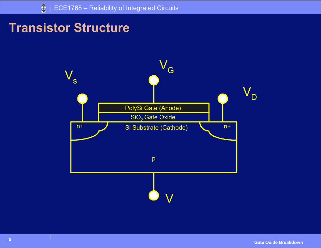
Transistor Structure
n+ n+
p
SiO2 Gate Oxide
Si Substrate (Cathode)
PolySi Gate (Anode)
6
ECE1768 – Reliability of Integrated Circuits
Gate Oxide Breakdown
Gate Oxide Traps
Defects in the Gate Oxide are called Traps– They can trap charges
Traps are usually neutral except for – Near the anode they quickly become negatively charged
– Near the cathode they quickly become positively charged
ECE1768 – Reliability of Integrated Circuits
Root Causes
8
ECE1768 – Reliability of Integrated Circuits
Gate Oxide Breakdown
What is Gate Oxide Breakdown?
Breakdown is defined as the time when there is a conduction path from the anode to the cathode through the gate oxide
Traps allow for creation of conduction path
Outline of this section– First we will see how traps lead to conduction paths
– Then we will investigate different physical methods for the creation of traps– The mathematics for these different physical models will be dealt later
9
ECE1768 – Reliability of Integrated Circuits
Gate Oxide Breakdown
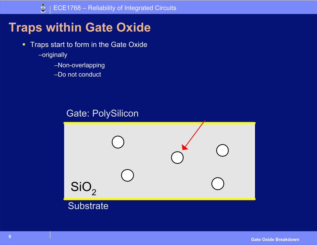
Traps within Gate OxideTraps start to form in the Gate Oxide
–originally–Non-overlapping–Do not conduct
10
ECE1768 – Reliability of Integrated Circuits
Gate Oxide Breakdown
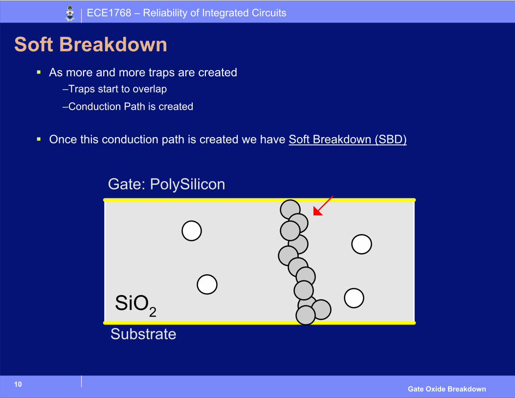
Soft BreakdownAs more and more traps are created
–Traps start to overlap
–Conduction Path is created
Once this conduction path is created we have Soft Breakdown (SBD)
11
ECE1768 – Reliability of Integrated Circuits
Gate Oxide Breakdown
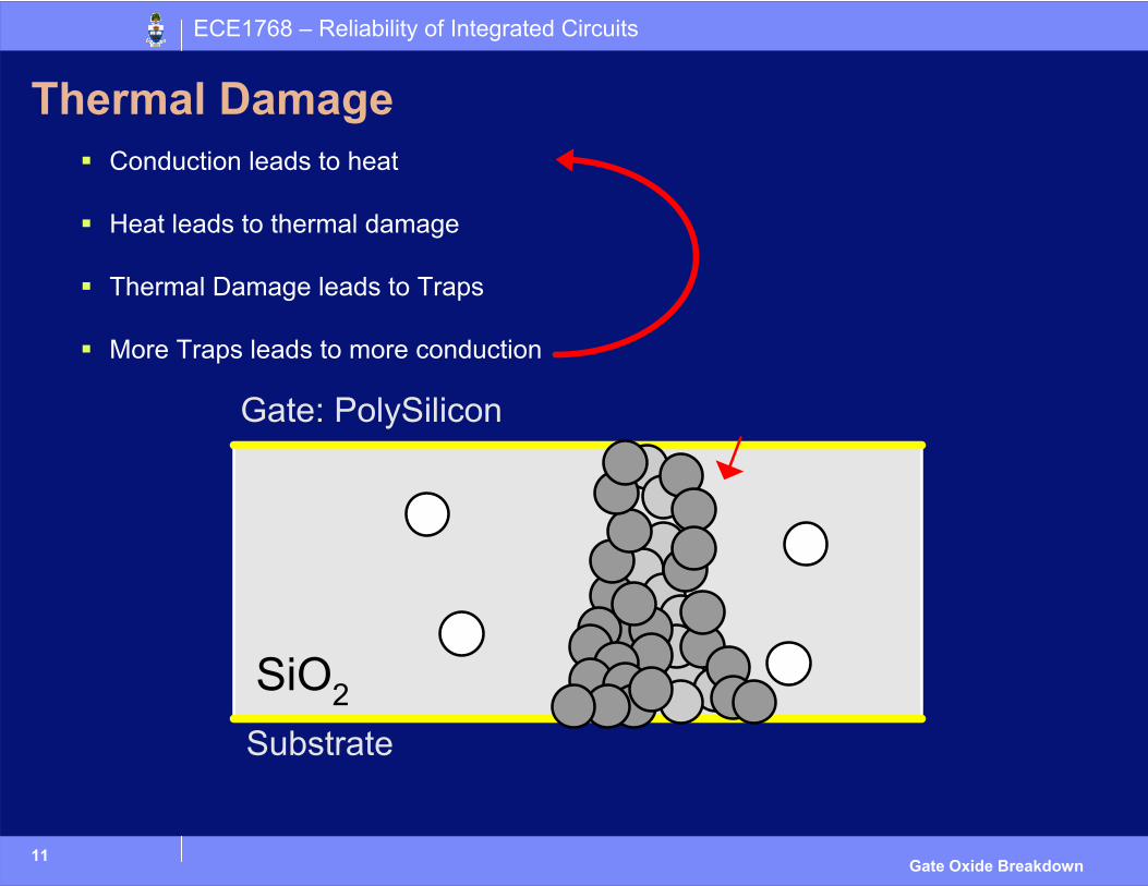
Thermal DamageConduction leads to heat
Heat leads to thermal damage
Thermal Damage leads to Traps
More Traps leads to more conduction
12
ECE1768 – Reliability of Integrated Circuits
Gate Oxide Breakdown
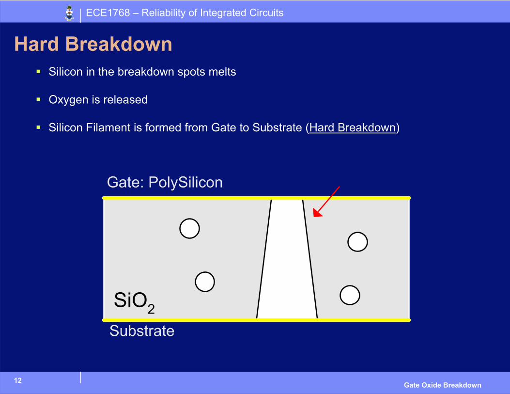
Hard BreakdownSilicon in the breakdown spots melts
Oxygen is released
Silicon Filament is formed from Gate to Substrate (Hard Breakdown)
13
ECE1768 – Reliability of Integrated Circuits
Gate Oxide Breakdown
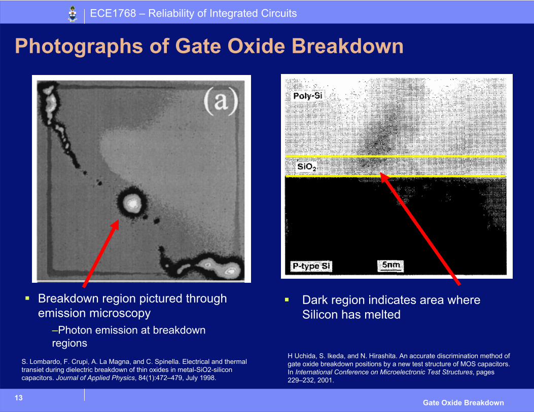
Photographs of Gate Oxide Breakdown
Breakdown region pictured through emission microscopy
–Photon emission at breakdown regions
Dark region indicates area where Silicon has melted
S. Lombardo, F. Crupi, A. La Magna, and C. Spinella. Electrical and thermaltransiet during dielectric breakdown of thin oxides in metal-SiO2-silicon capacitors. Journal of Applied Physics, 84(1):472–479, July 1998.
H Uchida, S. Ikeda, and N. Hirashita. An accurate discrimination method of gate oxide breakdown positions by a new test structure of MOS capacitors. In International Conference on Microelectronic Test Structures, pages 229–232, 2001.
14
ECE1768 – Reliability of Integrated Circuits
Gate Oxide Breakdown
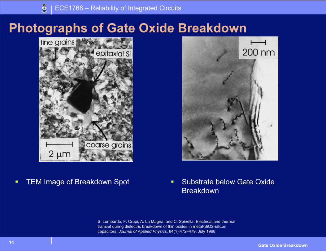
Photographs of Gate Oxide Breakdown
TEM Image of Breakdown Spot Substrate below Gate Oxide Breakdown
S. Lombardo, F. Crupi, A. La Magna, and C. Spinella. Electrical and thermaltransiet during dielectric breakdown of thin oxides in metal-SiO2-silicon capacitors. Journal of Applied Physics, 84(1):472–479, July 1998.
15
ECE1768 – Reliability of Integrated Circuits
Gate Oxide Breakdown
Trap Generation
Know how traps can cause Gate Oxide Breakdown
How are traps created?
Different Models (i.e. we’re not exactly sure how)– Thermochemical Model
– Anode Hole Injection
– Hydrogen Release
– Channel Hot Carriers
– Irradiation
Discuss the Physical Reasons– Math that leads to reliability projections for above models will be presented
later
Main Two Models
16
ECE1768 – Reliability of Integrated Circuits
Gate Oxide Breakdown
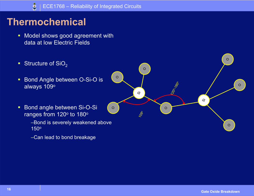
ThermochemicalModel shows good agreement with data at low Electric Fields
Structure of SiO2
Bond Angle between O-Si-O is always 109o
Bond angle between Si-O-Si ranges from 120o to 180o
–Bond is severely weakened above 150o
–Can lead to bond breakageSi
O
O
O
O
Si
O
O
O
109o
120o
-180
o
17
ECE1768 – Reliability of Integrated Circuits
Gate Oxide Breakdown
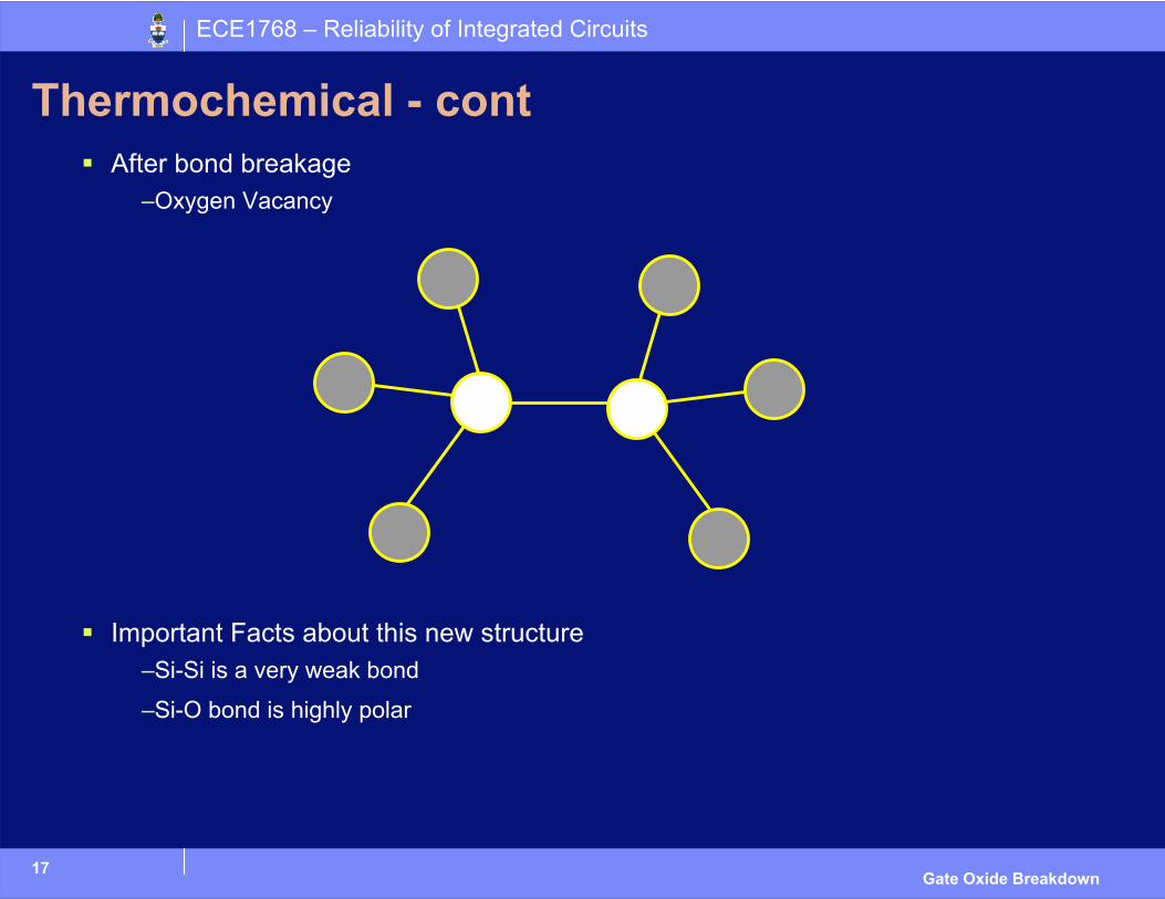
Thermochemical - contAfter bond breakage
–Oxygen Vacancy
Important Facts about this new structure–Si-Si is a very weak bond
–Si-O bond is highly polar
18
ECE1768 – Reliability of Integrated Circuits
Gate Oxide Breakdown
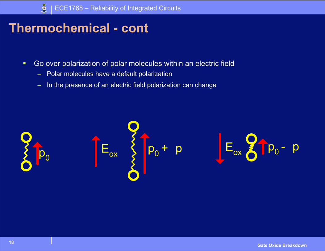
Thermochemical - cont
Go over polarization of polar molecules within an electric field– Polar molecules have a default polarization
– In the presence of an electric field polarization can change
19
ECE1768 – Reliability of Integrated Circuits
Gate Oxide Breakdown
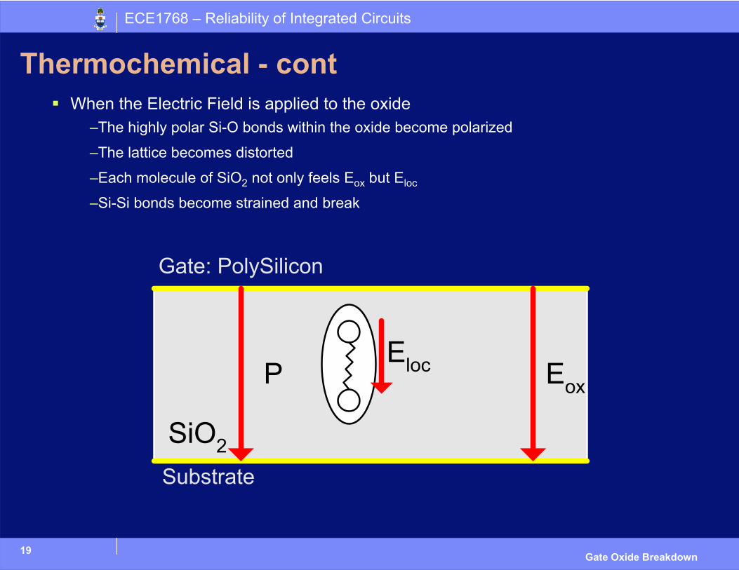
Thermochemical - contWhen the Electric Field is applied to the oxide
–The highly polar Si-O bonds within the oxide become polarized
–The lattice becomes distorted
–Each molecule of SiO2 not only feels Eox but Eloc
–Si-Si bonds become strained and break
20
ECE1768 – Reliability of Integrated Circuits
Gate Oxide Breakdown
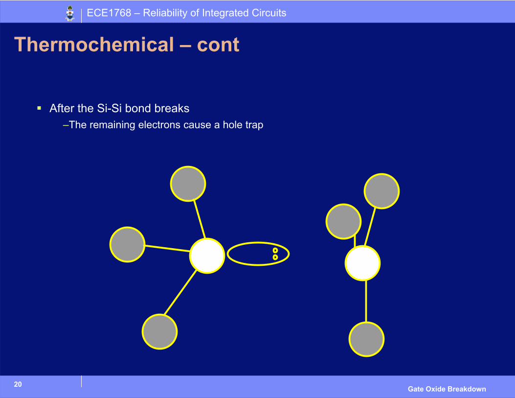
Thermochemical – cont
After the Si-Si bond breaks–The remaining electrons cause a hole trap
21
ECE1768 – Reliability of Integrated Circuits
Gate Oxide Breakdown
Anode Hole Injection
Model shows good agreement with data at high Electric Fields
High Electric Fields– Large tunneling current (electrons) through the oxide
– Electrons have high Kinetic Energy
– Electron hits the Gate Anode and transfers energy to Hole
– Hole tunnels back into the Gate Oxide
– Hole creates trap
22
ECE1768 – Reliability of Integrated Circuits
Gate Oxide Breakdown
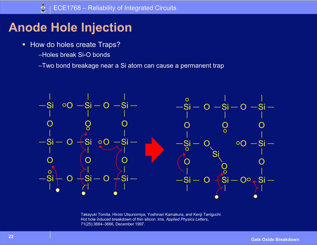
Anode Hole InjectionHow do holes create Traps?
–Holes break Si-O bonds
–Two bond breakage near a Si atom can cause a permanent trap
Takayuki Tomita, Hiroto Utsunomiya, Yoshinari Kamakura, and Kenji Taniguchi.Hot hole induced breakdown of thin silicon .lms. Applied Physics Letters,71(25):3664–3666, December 1997.
23
ECE1768 – Reliability of Integrated Circuits
Gate Oxide Breakdown
Hydrogen Release Model
Very similar to Anode Hole Injection Model– The AHI rate is too small to produce the defects that lead to breakdown
– Use Hydrogen instead of Holes to produce traps
Just as in AHI high energy electrons tunnel through oxide– Break Si-H bond at interface of gate oxide
– H+ ion (proton) is released into the oxide
– Proton reacts with oxygen vacancies to produce traps– (Si-Si)+H+ -> Si-H+ -Si
24
ECE1768 – Reliability of Integrated Circuits
Gate Oxide Breakdown
Channel Hot CarriersThermochemical, AHI and HR models can all explain gate oxide breakdown when there is no potential difference between drain and source
– There is data, however, that shows that gate oxide breakdown is more likely when there is a potential difference between drain and source
Hot Carriers– Electrons and Holes who, in the presence of high lateral fields, gain
sufficient energy that they are no longer in equilibrium with the lattice
The hot carriers create an electron-hole pair by impact ionization in the channel
– Hole enters the substrate
– Electron enters the gate oxide and may cause traps
25
ECE1768 – Reliability of Integrated Circuits
Gate Oxide Breakdown
Irradiation
Irradiation with ions can lead to oxide defects
Irradiation has no immediate impact by itself, the transistor works as it should
But transistors that have been irradiated, and then stressed break down more quickly
Exact nature of defects caused due to irradiation in gate oxide is unknown

ECE1768 – Reliability of Integrated Circuits
Symptoms
27
ECE1768 – Reliability of Integrated Circuits
Gate Oxide Breakdown
Symptoms of Breakdown
Transistor Characteristics– Hard Breakdown
– Soft Breakdown
Circuit Characteristics– Inverter
– Digital Logic
– SRAMs
– RF Circuitry
28
ECE1768 – Reliability of Integrated Circuits
Gate Oxide Breakdown
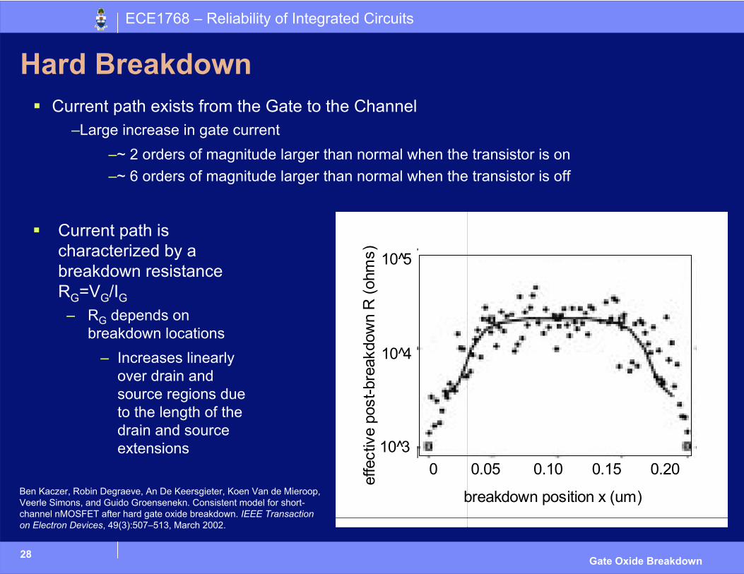
Hard BreakdownCurrent path exists from the Gate to the Channel
–Large increase in gate current–~ 2 orders of magnitude larger than normal when the transistor is on–~ 6 orders of magnitude larger than normal when the transistor is off
breakdown position x (um)
0 0.05 0.10 0.15 0.20
10 5̂
10 4̂
10 3̂
effe
ctiv
e po
st-b
reak
dow
n R
(ohm
s)
Current path is characterized by a breakdown resistance RG=VG/IG
– RG depends on breakdown locations
– Increases linearly over drain and source regions due to the length of the drain and source extensions
Ben Kaczer, Robin Degraeve, An De Keersgieter, Koen Van de Mieroop, Veerle Simons, and Guido Groensenekn. Consistent model for short-channel nMOSFET after hard gate oxide breakdown. IEEE Transaction on Electron Devices, 49(3):507–513, March 2002.
29
ECE1768 – Reliability of Integrated Circuits
Gate Oxide Breakdown
Hard Breakdown Continued
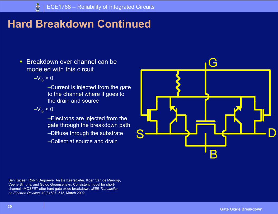
Breakdown over channel can be modeled with this circuit
–VG > 0–Current is injected from the gate to the channel where it goes to the drain and source
–VG < 0–Electrons are injected from the gate through the breakdown path–Diffuse through the substrate–Collect at source and drain
Ben Kaczer, Robin Degraeve, An De Keersgieter, Koen Van de Mieroop, Veerle Simons, and Guido Groensenekn. Consistent model for short-channel nMOSFET after hard gate oxide breakdown. IEEE Transaction on Electron Devices, 49(3):507–513, March 2002.
30
ECE1768 – Reliability of Integrated Circuits
Gate Oxide Breakdown
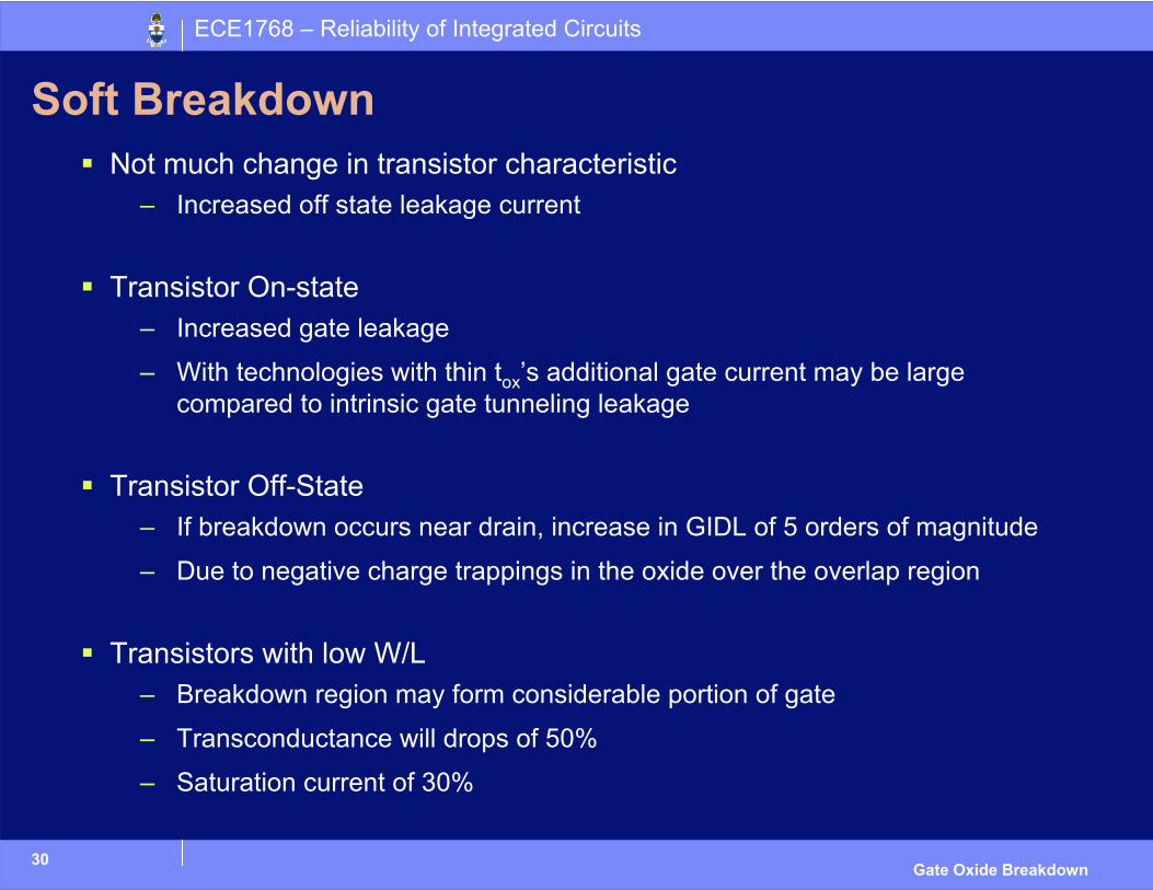
Soft BreakdownNot much change in transistor characteristic
– Increased off state leakage current
Transistor On-state– Increased gate leakage
– With technologies with thin tox’s additional gate current may be large compared to intrinsic gate tunneling leakage
Transistor Off-State– If breakdown occurs near drain, increase in GIDL of 5 orders of magnitude
– Due to negative charge trappings in the oxide over the overlap region
Transistors with low W/L– Breakdown region may form considerable portion of gate
– Transconductance will drops of 50%
– Saturation current of 30%
31
ECE1768 – Reliability of Integrated Circuits
Gate Oxide Breakdown
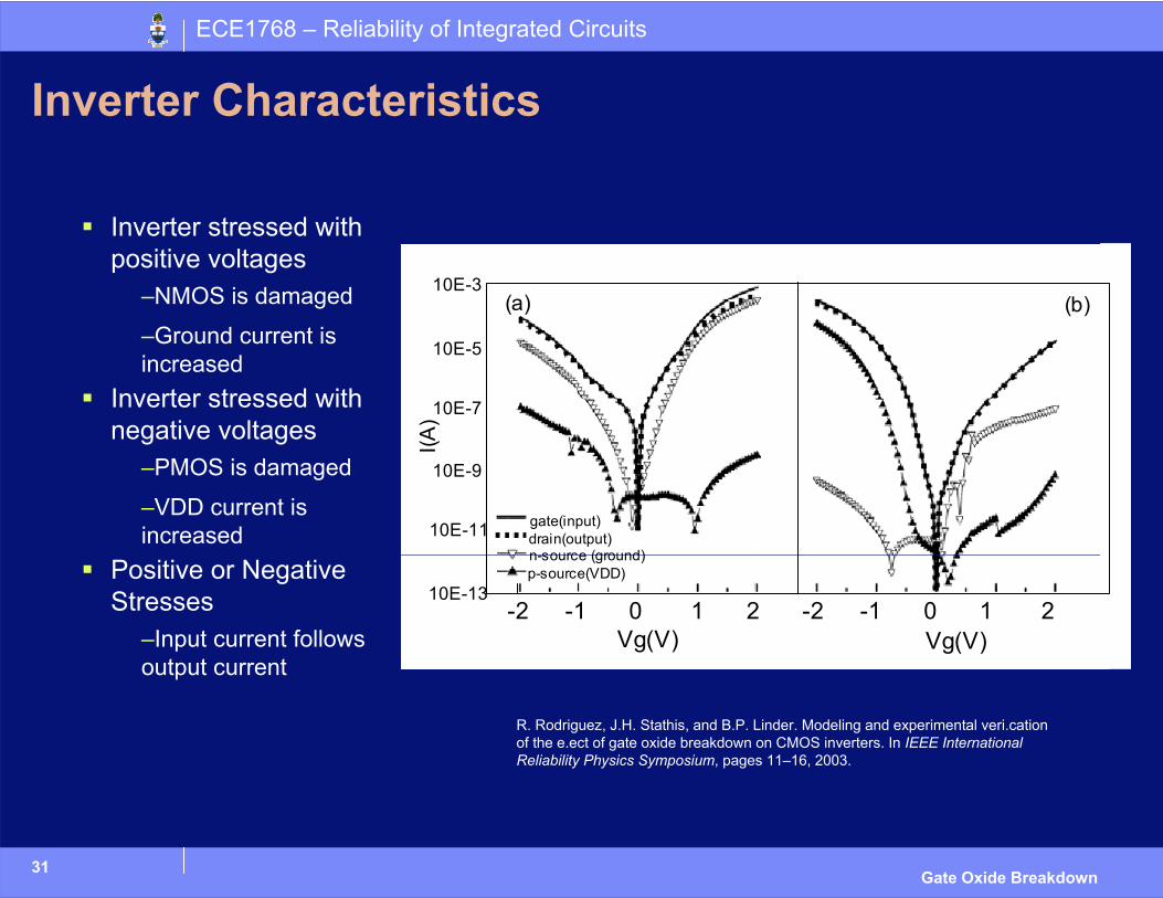
Inverter Characteristics
Inverter stressed with positive voltages
–NMOS is damaged
–Ground current is increased
Inverter stressed with negative voltages
–PMOS is damaged
–VDD current is increased
Positive or Negative Stresses
–Input current follows output current
Vg(V) Vg(V)-2 -1 0 1 2 -2 -1 0 1 2
10E-3 10E-5 10E-7
10E-9
10E-11
10E-13
I(A)
(a) (b)
gate(input)drain(output)n-source (ground)p-source(VDD)
R. Rodriguez, J.H. Stathis, and B.P. Linder. Modeling and experimental veri.cationof the e.ect of gate oxide breakdown on CMOS inverters. In IEEE InternationalReliability Physics Symposium, pages 11–16, 2003.
32
ECE1768 – Reliability of Integrated Circuits
Gate Oxide Breakdown
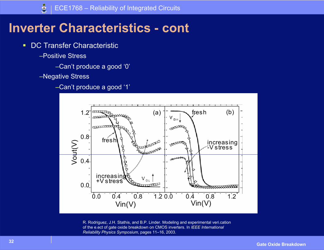
Inverter Characteristics - contDC Transfer Characteristic
–Positive Stress–Can’t produce a good ‘0’
–Negative Stress–Can’t produce a good ‘1’
1.2 0.8 0.4 0.0
0.0 0.4 0.8 1.2 0.0 0.4 0.8 1.2Vin(V) Vin(V)
Vout
(V)
(a) (b)
increasing -V stress
fresh
fresh
increasing +V stress
R. Rodriguez, J.H. Stathis, and B.P. Linder. Modeling and experimental veri.cationof the e.ect of gate oxide breakdown on CMOS inverters. In IEEE InternationalReliability Physics Symposium, pages 11–16, 2003.
33
ECE1768 – Reliability of Integrated Circuits
Gate Oxide Breakdown
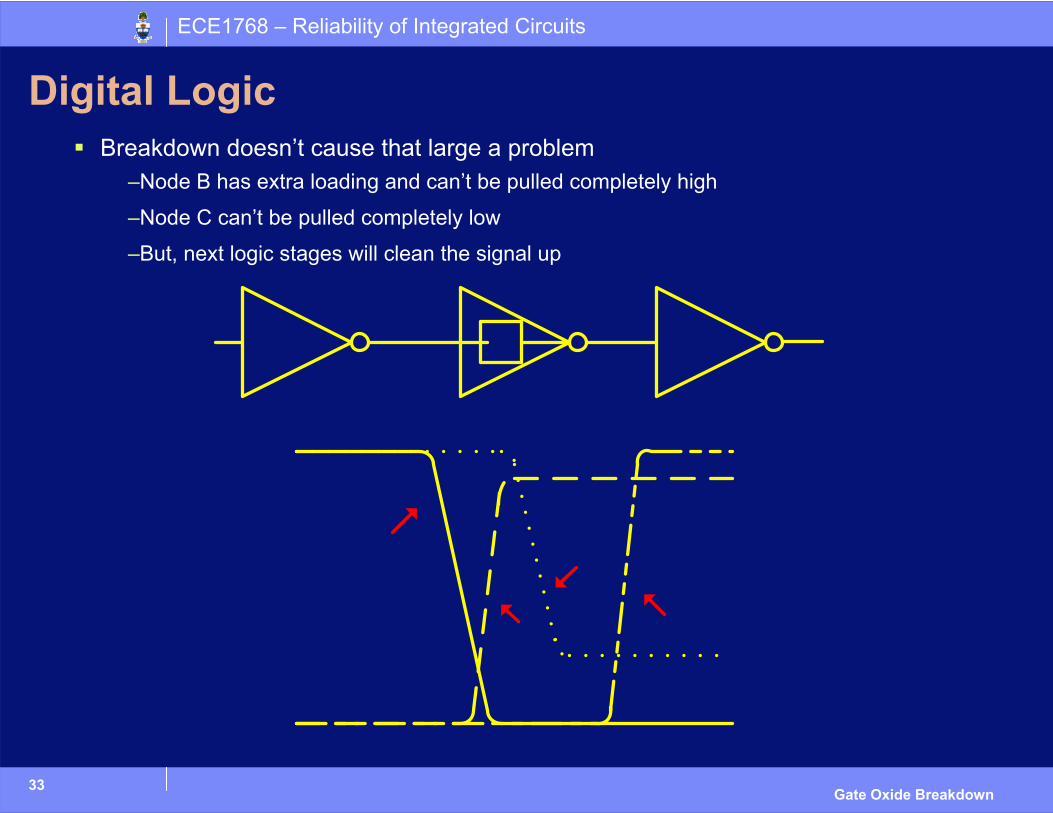
Digital LogicBreakdown doesn’t cause that large a problem
–Node B has extra loading and can’t be pulled completely high
–Node C can’t be pulled completely low
–But, next logic stages will clean the signal up

34
ECE1768 – Reliability of Integrated Circuits
Gate Oxide Breakdown
Digital Logic - cont
Ring Oscillator Example–Functions, albeit at lower frequency, after many breakdowns
–Increase in leakage current
stress time (s)
off I
osc
(mA
)
30 20 10 0 0 100 200 300
outp
ut fr
eque
ncy
(MH
z)1.7 1.6
Vosc = 4.4V Vinp = 0V Vdb = 1.5V
Vosc = 1.5V Vinp = 1.5V Vdb = 1.5V
time
final
i
nitia
l Vosc = 1.5V Vinp = 1.5V Vdb = 1.5V
Ben Kaczer, Robin Degraeve, Mahmoud Rasras, Koen Van de Mieroop, Philippe J.Roussel, and Guido Groensenekn. Impact of MOSFET gate oxide breakdown ondigital circuit operation and reliability. IEEE Transaction on Electron Devices,49(3):500–507, March 2002.
35
ECE1768 – Reliability of Integrated Circuits
Gate Oxide Breakdown
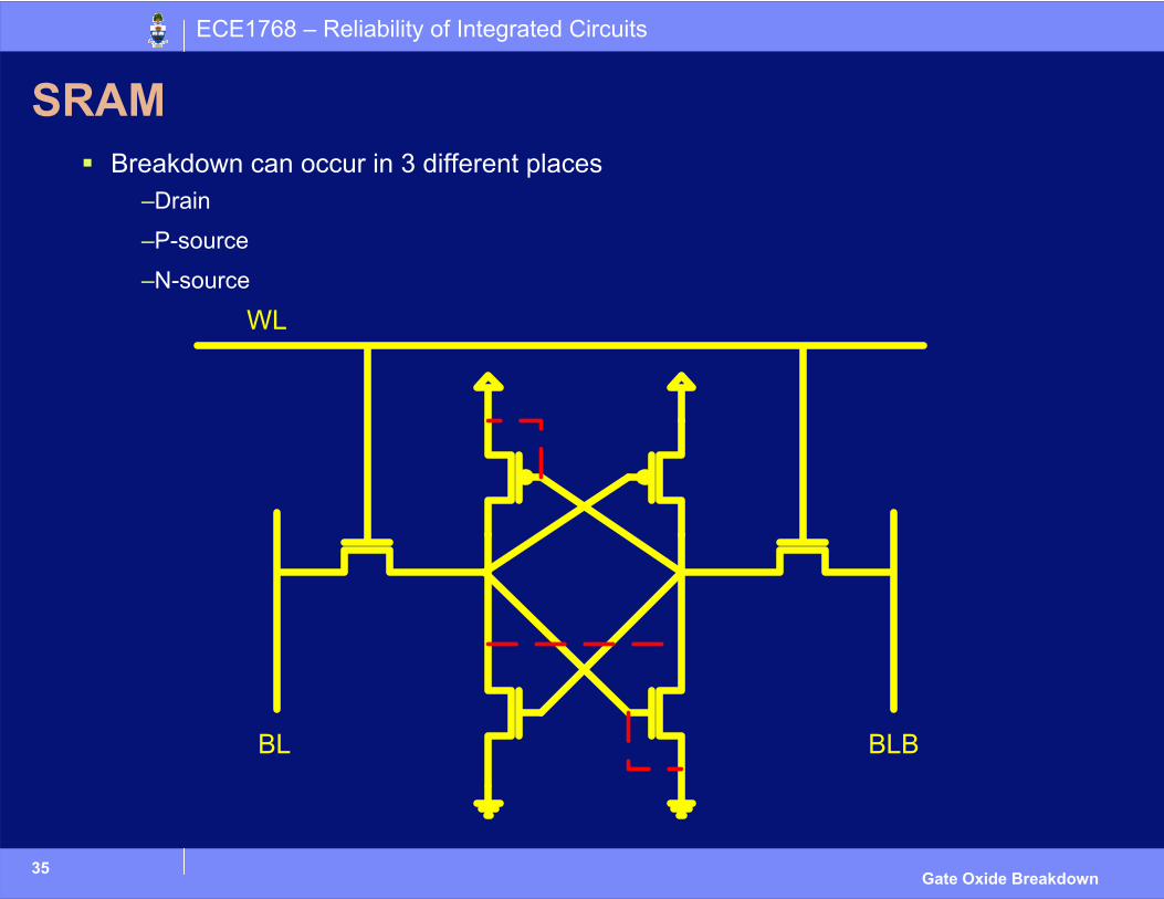
SRAMBreakdown can occur in 3 different places
–Drain
–P-source
–N-source
36
ECE1768 – Reliability of Integrated Circuits
Gate Oxide Breakdown
SRAM - cont
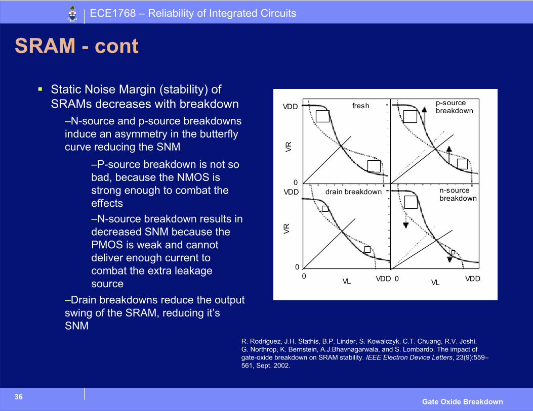
Static Noise Margin (stability) of SRAMs decreases with breakdown
–N-source and p-source breakdowns induce an asymmetry in the butterfly curve reducing the SNM
–P-source breakdown is not so bad, because the NMOS is strong enough to combat the effects–N-source breakdown results in decreased SNM because the PMOS is weak and cannot deliver enough current to combat the extra leakage source
–Drain breakdowns reduce the output swing of the SRAM, reducing it’s SNM
fresh p-source breakdown
drain breakdown n-source breakdown
VDD
VDD0
00 VDD 0 VDD VL VL
VR
VR
R. Rodriguez, J.H. Stathis, B.P. Linder, S. Kowalczyk, C.T. Chuang, R.V. Joshi,G. Northrop, K. Bernstein, A.J.Bhavnagarwala, and S. Lombardo. The impact ofgate-oxide breakdown on SRAM stability. IEEE Electron Device Letters, 23(9):559–561, Sept. 2002.
37
ECE1768 – Reliability of Integrated Circuits
Gate Oxide Breakdown
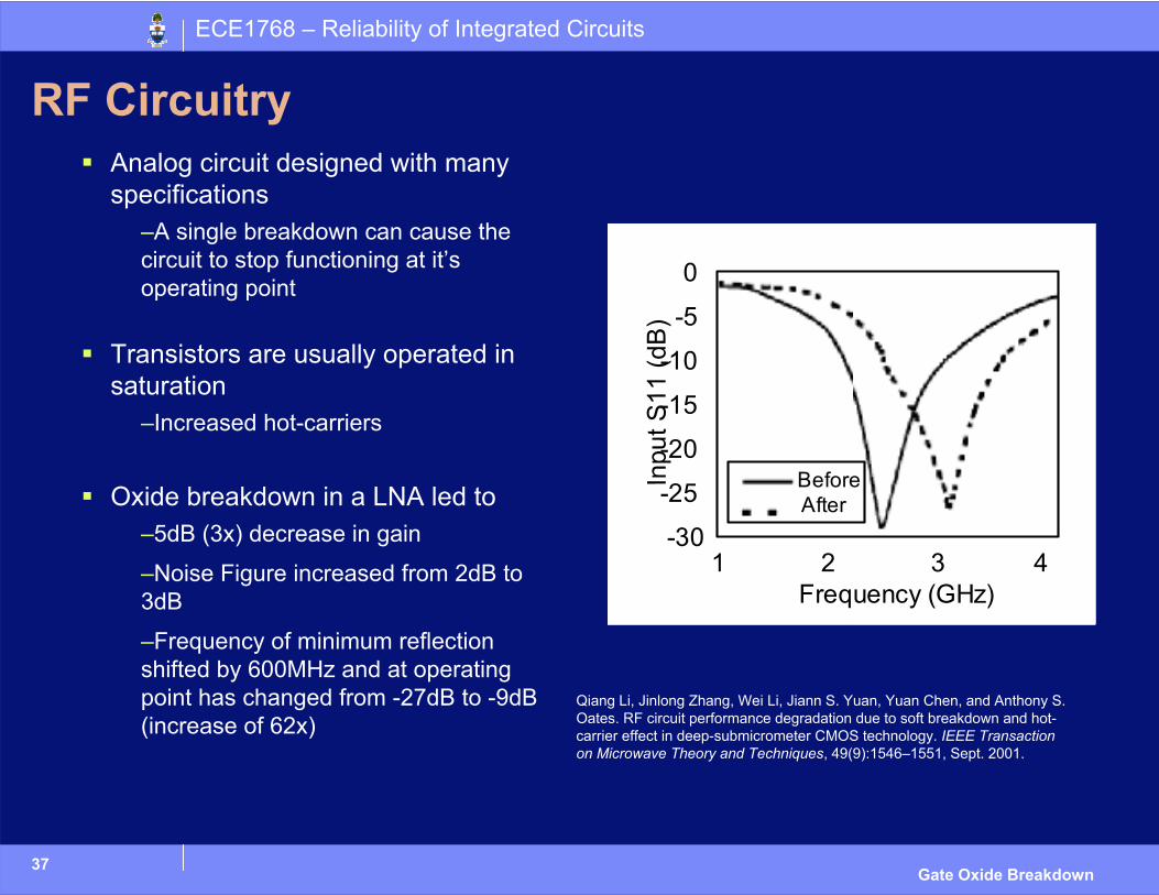
RF CircuitryAnalog circuit designed with many specifications
–A single breakdown can cause the circuit to stop functioning at it’s operating point
Transistors are usually operated in saturation
–Increased hot-carriers
Oxide breakdown in a LNA led to–5dB (3x) decrease in gain
–Noise Figure increased from 2dB to 3dB
–Frequency of minimum reflection shifted by 600MHz and at operating point has changed from -27dB to -9dB (increase of 62x)
Frequency (GHz)1 2 3 4
0
-5
-10
-15
-20
-25
-30
Inpu
t S11
(dB
)
BeforeAfter
Qiang Li, Jinlong Zhang, Wei Li, Jiann S. Yuan, Yuan Chen, and Anthony S.Oates. RF circuit performance degradation due to soft breakdown and hot-carrier effect in deep-submicrometer CMOS technology. IEEE Transaction on Microwave Theory and Techniques, 49(9):1546–1551, Sept. 2001.
ECE1768 – Reliability of Integrated Circuits
Failure Models
39
ECE1768 – Reliability of Integrated Circuits
Gate Oxide Breakdown
Goals of our Failure Model
Mapping from device parameters – Area, thickness, activation energies, etc.
and usage conditions – Field, current, temperature, etc.
to breakdown occurrence– Time (tbd) or charge (Qbd)
40
ECE1768 – Reliability of Integrated Circuits
Gate Oxide Breakdown
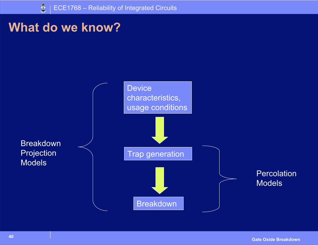
What do we know?
Device characteristics, usage conditions
Trap generation
Breakdown
Percolation Models
Breakdown Projection Models
41
ECE1768 – Reliability of Integrated Circuits
Gate Oxide Breakdown
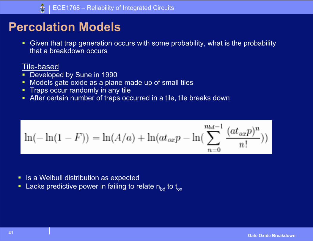
Percolation ModelsGiven that trap generation occurs with some probability, what is the probability that a breakdown occurs
Tile-basedDeveloped by Sune in 1990Models gate oxide as a plane made up of small tilesTraps occur randomly in any tileAfter certain number of traps occurred in a tile, tile breaks down
Is a Weibull distribution as expectedLacks predictive power in failing to relate nbd to tox
42
ECE1768 – Reliability of Integrated Circuits
Gate Oxide Breakdown
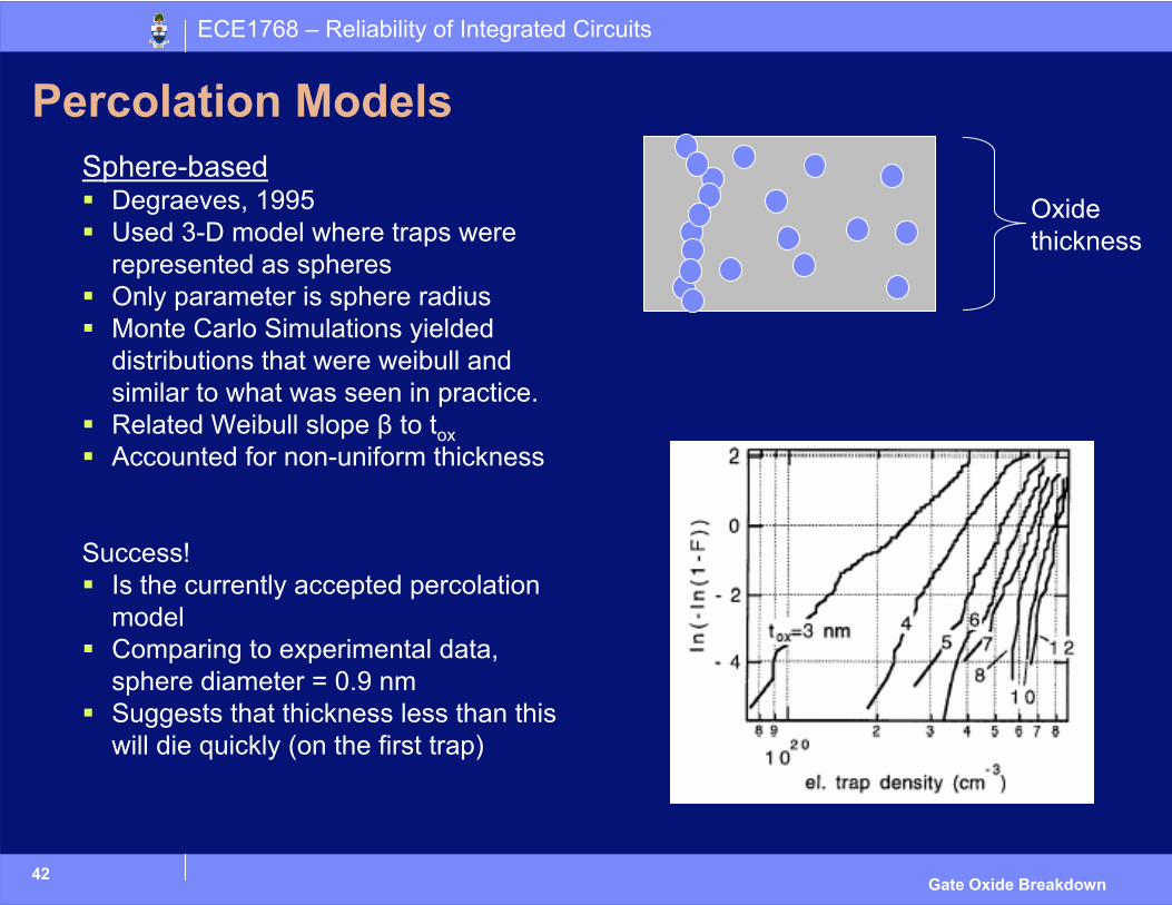
Percolation ModelsSphere-based
Degraeves, 1995Used 3-D model where traps were represented as spheresOnly parameter is sphere radiusMonte Carlo Simulations yielded distributions that were weibull and similar to what was seen in practice.Related Weibull slope β to toxAccounted for non-uniform thickness
Success!Is the currently accepted percolation modelComparing to experimental data, sphere diameter = 0.9 nmSuggests that thickness less than this will die quickly (on the first trap)
Oxide thickness
43
ECE1768 – Reliability of Integrated Circuits
Gate Oxide Breakdown
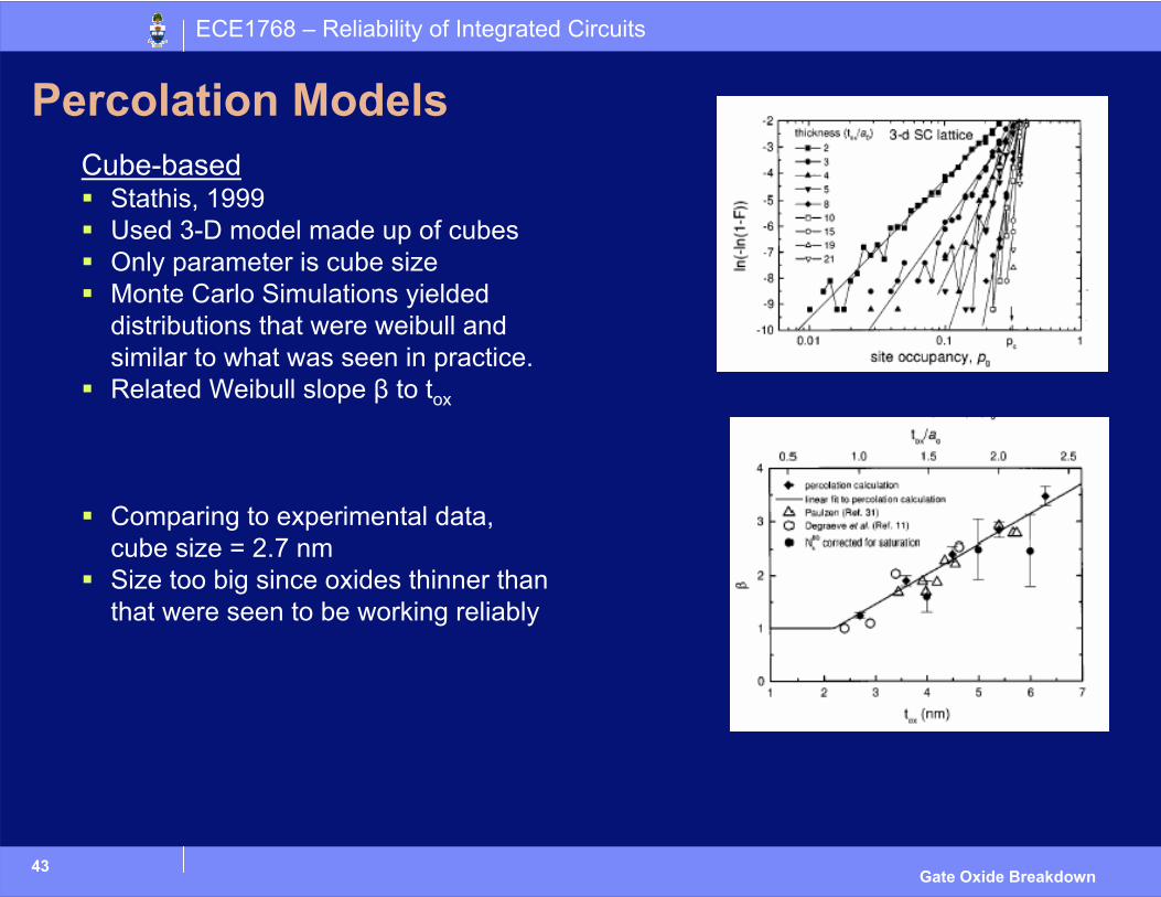
Percolation ModelsCube-based
Stathis, 1999Used 3-D model made up of cubesOnly parameter is cube sizeMonte Carlo Simulations yielded distributions that were weibull and similar to what was seen in practice.Related Weibull slope β to tox
Comparing to experimental data, cube size = 2.7 nmSize too big since oxides thinner than that were seen to be working reliably
44
ECE1768 – Reliability of Integrated Circuits
Gate Oxide Breakdown
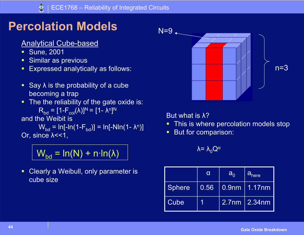
Percolation ModelsAnalytical Cube-based
Sune, 2001Similar as previousExpressed analytically as follows:
Say λ is the probability of a cube becoming a trapThe the reliability of the gate oxide is:
Rbd = [1-Fcol(λ)]N = [1- λn]Nand the Weibit is
Wbd = ln[-ln(1-Fbd)] = ln[-Nln(1- λn)]Or, since λ<<1,
Wbd = ln(N) + n·ln(λ)
Clearly a Weibull, only parameter is cube size
n=3
N=9
But what is λ?This is where percolation models stopBut for comparison:
λ= λ0Qα
2.34nm2.7nm1Cube
1.17nm0.9nm0.56Sphere
aherea0α
45
ECE1768 – Reliability of Integrated Circuits
Gate Oxide Breakdown
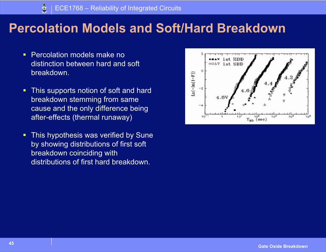
Percolation Models and Soft/Hard Breakdown
Percolation models make no distinction between hard and soft breakdown.
This supports notion of soft and hard breakdown stemming from same cause and the only difference being after-effects (thermal runaway)
This hypothesis was verified by Suneby showing distributions of first soft breakdown coinciding with distributions of first hard breakdown.
46
ECE1768 – Reliability of Integrated Circuits
Gate Oxide Breakdown
Breakdown Projection Models
Breakdown projection models are closest thing we have to failure modelsGoal is to predict time to failure Very controversial – physicists working on percolation models criticize all research in this area.Often incomplete/unusableTwo different families of breakdown projection models: E and 1/E
47
ECE1768 – Reliability of Integrated Circuits
Gate Oxide Breakdown
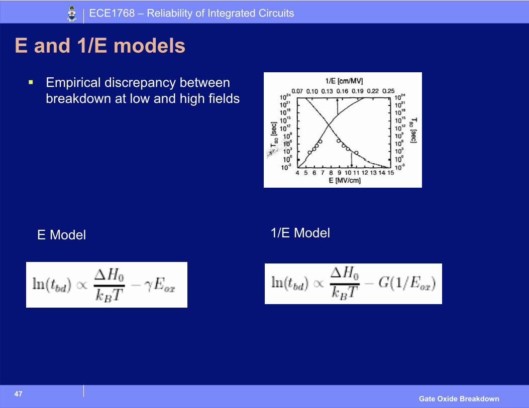
E and 1/E models
E Model 1/E Model
Empirical discrepancy between breakdown at low and high fields
48
ECE1768 – Reliability of Integrated Circuits
Gate Oxide Breakdown
Breakdown Projection Model Candidates
There are several models– Traditionally sided with either E or 1/E model, not both
– Many not developed enough to be used yet
– Some were absorbed by better models
The two main candidates:1. AHI model (1/E model)
2. Thermochemical model (E model)
Both are currently attempting to unify the E and 1/E model
49
ECE1768 – Reliability of Integrated Circuits
Gate Oxide Breakdown
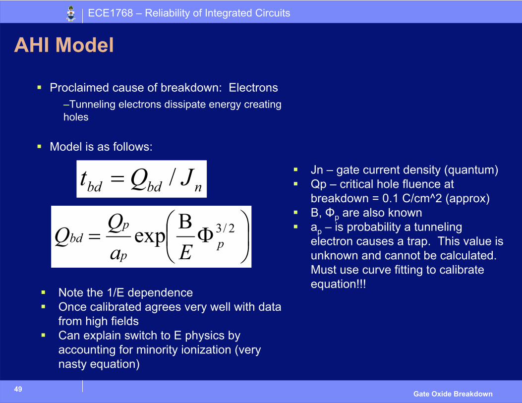
AHI Model
Proclaimed cause of breakdown: Electrons–Tunneling electrons dissipate energy creating holes
Model is as follows:
ΦΒ
= 2/3exp pp
pbd
EaQQ
nbdbd JQt /=
Note the 1/E dependenceOnce calibrated agrees very well with data from high fieldsCan explain switch to E physics by accounting for minority ionization (very nasty equation)
Jn – gate current density (quantum)Qp – critical hole fluence at breakdown = 0.1 C/cm^2 (approx)B, Φp are also knownap – is probability a tunneling electron causes a trap. This value is unknown and cannot be calculated. Must use curve fitting to calibrate equation!!!
50
ECE1768 – Reliability of Integrated Circuits
Gate Oxide Breakdown
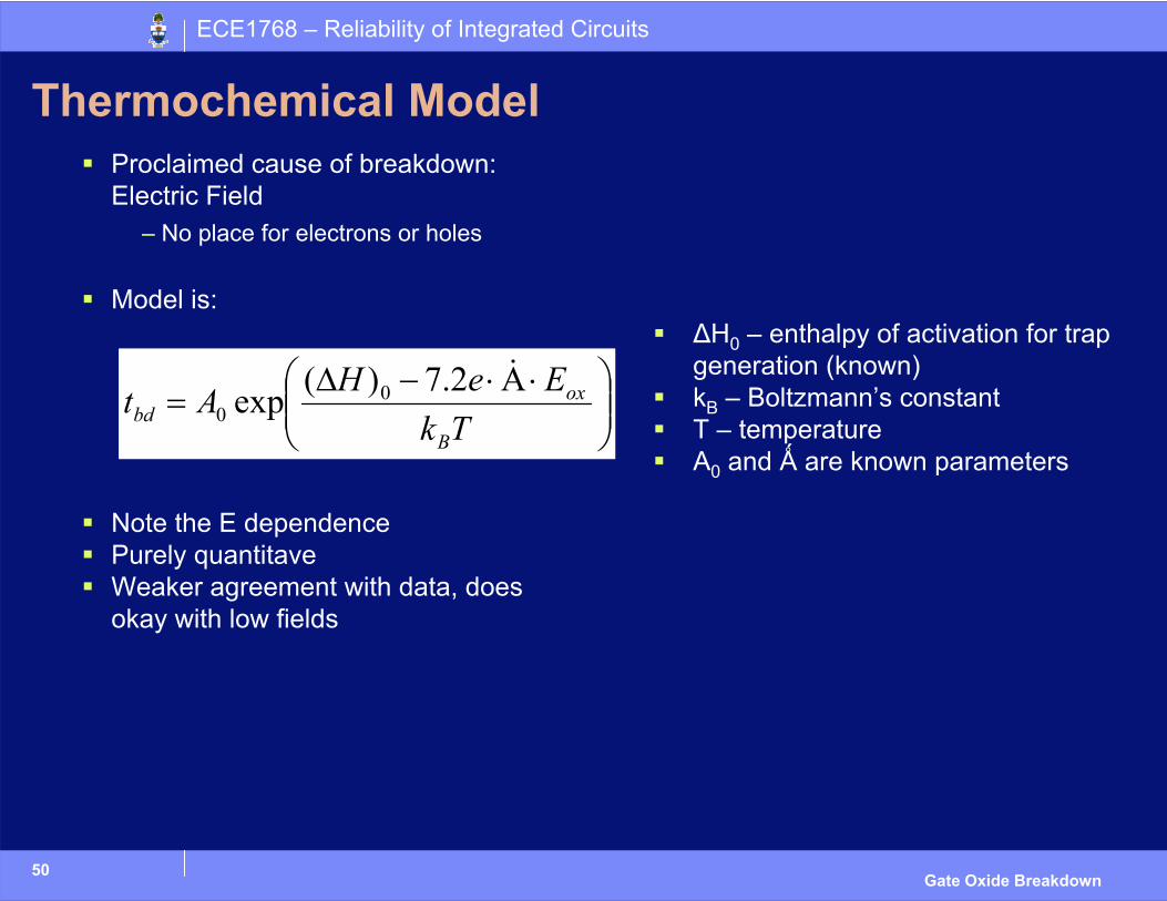
Thermochemical ModelProclaimed cause of breakdown: Electric Field
– No place for electrons or holes
Model is:
Note the E dependencePurely quantitaveWeaker agreement with data, does okay with low fields
⋅Α⋅−∆=
TkEeHAt
B
oxbd
&2.7)(exp 00
∆H0 – enthalpy of activation for trap generation (known)kB – Boltzmann’s constantT – temperatureA0 and Ǻ are known parameters
51
ECE1768 – Reliability of Integrated Circuits
Gate Oxide Breakdown
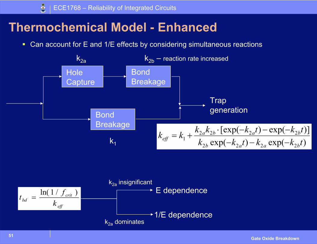
Thermochemical Model - EnhancedCan account for E and 1/E effects by considering simultaneous reactions
)exp()exp()]exp()[exp(
2222
22221 tkktkk
tktkkkkkbaab
babaeff −−−
−−−⋅+=
Hole Capture
Bond Breakage
Bond Breakage
Trap generation
k1
k2a k2b – reaction rate increased
eff
critbd k
ft )/1ln(=
E dependence
1/E dependence
k2a insignificant
k2a dominates

ECE1768 – Reliability of Integrated Circuits
Prediction
53
ECE1768 – Reliability of Integrated Circuits
Gate Oxide Breakdown
PredictionChoice of model still controversial, still being researched
Can not be done at the design phase– TC model can, but agreement is for small range of E and even then
questionable– AHI model requires experiment and curve fitting
Further complicated– Breakdowns may not cause failures– Coupling between parameters
– Model & field– Physical constants & device geometry
Prediction done through trial & error using accelerated testing1. Apply CVS/CCS for elevated Temperature and Voltage2. Extrapolate for Temperature, Voltage, and device Area3. Using Weibull, extrapolate for all failure rates
54
ECE1768 – Reliability of Integrated Circuits
Gate Oxide Breakdown
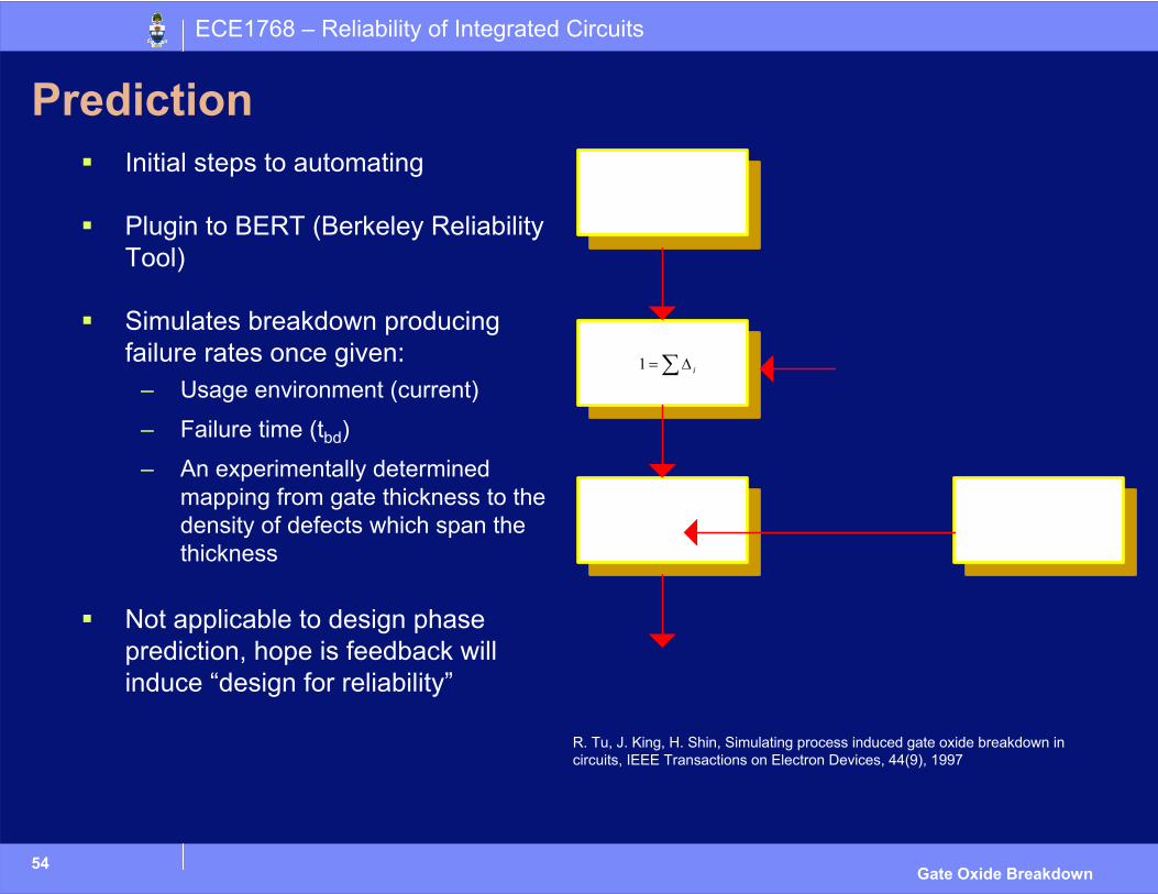
PredictionInitial steps to automating
Plugin to BERT (Berkeley Reliability Tool)
Simulates breakdown producing failure rates once given:
– Usage environment (current)
– Failure time (tbd)
– An experimentally determined mapping from gate thickness to the density of defects which span the thickness
Not applicable to design phase prediction, hope is feedback will induce “design for reliability”
R. Tu, J. King, H. Shin, Simulating process induced gate oxide breakdown in circuits, IEEE Transactions on Electron Devices, 44(9), 1997
∑∆= i1
ECE1768 – Reliability of Integrated Circuits
Protection
56
ECE1768 – Reliability of Integrated Circuits
Gate Oxide Breakdown
Protection against Gate Oxide Breakdown
We have seen that breakdown depends on the– Electric Field (Thermochemical and AHI models)
– Hot Carriers
What can we do to reduce the probability of Breakdown– Guarantee that the oxide doesn’t experience Electric Fields larger than it
was designed for (Voltage across gate should not be larger than VDD)
– Minimize the current through a transistor when it is in saturation
57
ECE1768 – Reliability of Integrated Circuits
Gate Oxide Breakdown
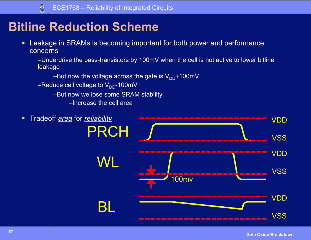
Bitline Reduction SchemeLeakage in SRAMs is becoming important for both power and performance concerns
–Underdrive the pass-transistors by 100mV when the cell is not active to lower bitline leakage
–But now the voltage across the gate is VDD+100mV–Reduce cell voltage to VDD-100mV
–But now we lose some SRAM stability–Increase the cell area
Tradeoff area for reliability
58
ECE1768 – Reliability of Integrated Circuits
Gate Oxide Breakdown
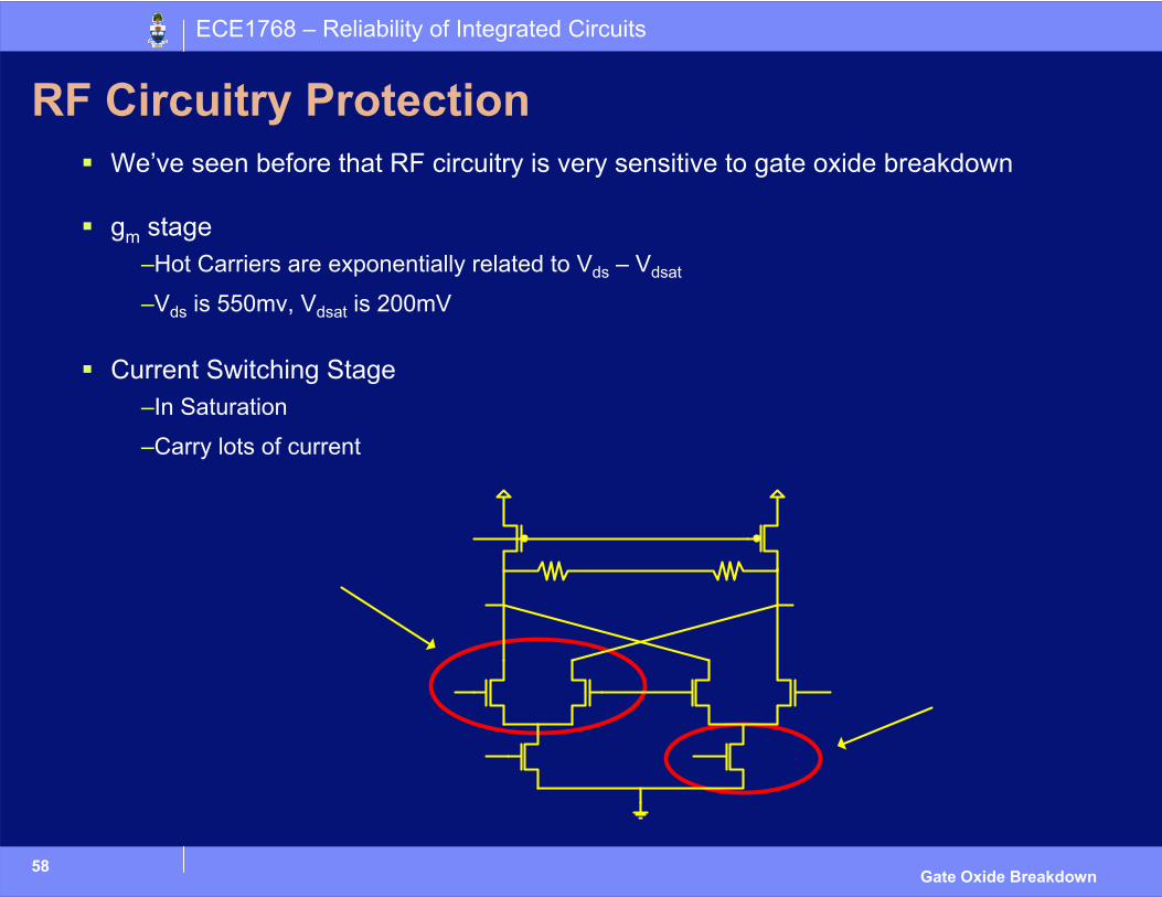
RF Circuitry ProtectionWe’ve seen before that RF circuitry is very sensitive to gate oxide breakdown
gm stage–Hot Carriers are exponentially related to Vds – Vdsat
–Vds is 550mv, Vdsat is 200mV
Current Switching Stage–In Saturation
–Carry lots of current
59
ECE1768 – Reliability of Integrated Circuits
Gate Oxide Breakdown
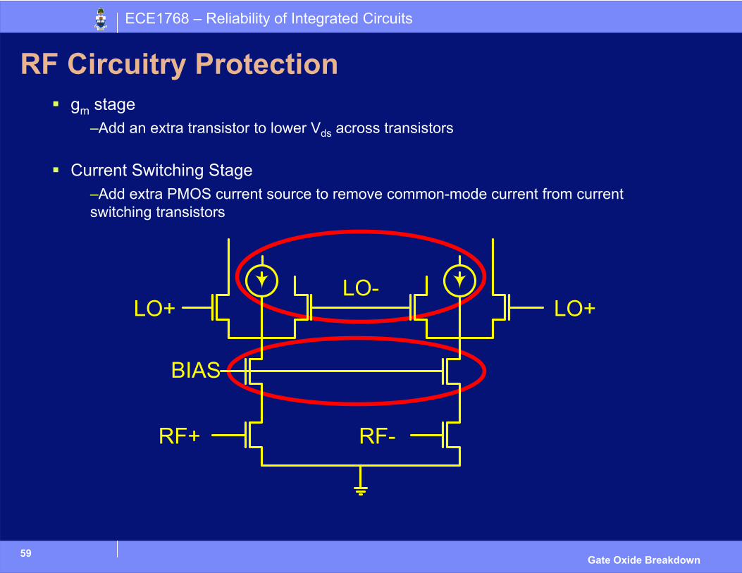
RF Circuitry Protectiongm stage
–Add an extra transistor to lower Vds across transistors
Current Switching Stage–Add extra PMOS current source to remove common-mode current from current switching transistors
60
ECE1768 – Reliability of Integrated Circuits
Gate Oxide Breakdown
ConclusionGate-oxide breakdown caused by trap generation
Trap Generation Models– AHI
– Thermochemical
– No unified model
Predicting gate-oxide breakdown is difficult
To protect against gate-oxide breakdown– Voltage across gate-oxide should not be larger than VDD
– Reduce hot-carriers